WO2012048691A2 - Verfahren und vorrichtung zur elektrischen erregung eines aktors für einen ultraschallmotor - Google Patents
Verfahren und vorrichtung zur elektrischen erregung eines aktors für einen ultraschallmotor Download PDFInfo
- Publication number
- WO2012048691A2 WO2012048691A2 PCT/DE2011/050037 DE2011050037W WO2012048691A2 WO 2012048691 A2 WO2012048691 A2 WO 2012048691A2 DE 2011050037 W DE2011050037 W DE 2011050037W WO 2012048691 A2 WO2012048691 A2 WO 2012048691A2
- Authority
- WO
- WIPO (PCT)
- Prior art keywords
- voltage
- current
- actuator
- piezoelectric
- electrical
- Prior art date
- Legal status (The legal status is an assumption and is not a legal conclusion. Google has not performed a legal analysis and makes no representation as to the accuracy of the status listed.)
- Ceased
Links
Images


Classifications
-
- H—ELECTRICITY
- H02—GENERATION; CONVERSION OR DISTRIBUTION OF ELECTRIC POWER
- H02N—ELECTRIC MACHINES NOT OTHERWISE PROVIDED FOR
- H02N2/00—Electric machines in general using piezoelectric effect, electrostriction or magnetostriction
- H02N2/02—Electric machines in general using piezoelectric effect, electrostriction or magnetostriction producing linear motion, e.g. actuators; Linear positioners ; Linear motors
- H02N2/06—Drive circuits; Control arrangements or methods
-
- H—ELECTRICITY
- H02—GENERATION; CONVERSION OR DISTRIBUTION OF ELECTRIC POWER
- H02N—ELECTRIC MACHINES NOT OTHERWISE PROVIDED FOR
- H02N2/00—Electric machines in general using piezoelectric effect, electrostriction or magnetostriction
- H02N2/0005—Electric machines in general using piezoelectric effect, electrostriction or magnetostriction producing non-specific motion; Details common to machines covered by H02N2/02 - H02N2/16
- H02N2/0075—Electrical details, e.g. drive or control circuits or methods
- H02N2/008—Means for controlling vibration frequency or phase, e.g. for resonance tracking
Definitions
- the present invention relates to a method and a device for the electrical excitation of an actuator for an ultrasonic motor.
- the disadvantage of this method and the corresponding exciter device is that the phase difference between the electrical excitation voltage of the actuator and the voltage of the auxiliary electrode depends on the mechanical load on the actuator. Therefore, in the case of high mechanical loads on the ultrasonic actuator in these motors, the frequency of the excitation electric voltage is not equal to the mechanical resonance frequency of the ultrasonic actuator. This has a destabilizing effect on the function of the ultrasonic motor.
- the auxiliary electrode must have a large area for safe operation, which in turn reduces the area for the excitation electrodes and causes an increase in the excitation voltage.
- the auxiliary electrode must have an additional output in the form of a thin wire. At high moving speeds of the movable element, this reduces the reliability of the motors.
- US Pat. No. 5,872,418 discloses, for example, a method and a device for exciting an ultrasound motor, wherein the frequency of the electrical exciter voltage of the ultrasound actuator is regulated by maintaining a constant phase difference between the voltage that excites the actuator and the current flowing through it ,
- a sinusoidal electrical voltage is applied to the piezoelectric element of the ultrasonic actuator, which excites the ultrasonic actuator.
- the applied sine voltage causes a sinusoidal current to flow through the piezo element.
- the disadvantage of this method is also that the phase difference between the electrical excitation voltage and the current flowing through the piezoelectric element depends on the mechanical load on the ultrasonic actuator. This is due to the fact that the sinusoidal current flowing through the piezoelectric element has two components, namely a capacitive current flowing through the electrical capacitance of the piezoelectric element, and a piezoelectric current, which is determined by the angle of rotation of the domains of the piezoelectric element. At the mechanical resonance frequency, the piezoelectric current represents a so-called active current or active current. With a small mechanical load on the ultrasonic actuator, the active resistance of the actuator is significantly smaller than its reactive resistance.
- the phase shift between the excitation voltage and the current flowing through the piezoelectric element is small at the mechanical resonance frequency and approaches zero.
- Increasing the mechanical load applied to the actuator increases the active resistance while the reactive resistance remains constant. Therefore, the increase in the mechanical load causes an increase in the displacement angle between the excitation voltage and the current flowing through the piezoelectric element of the ultrasonic actuator.
- the phase shift angle of several degrees may increase ten times or more.
- the oscillations of the phase shift are caused not only by a mechanical load on the element to be driven, but also by a ripple of the friction surface and by a mechanical imbalance of the driven element.
- This destabilization causes the excitation voltage to increase and the required current and power to increase.
- speed oscillations of the element to be driven occur.
- the maximum force that can be generated by the engine is reduced. This force depends on the position of the element to be driven.
- the motor can come to a standstill and the actuator heat up. By means of said heating, the temperature range of use for the ultrasonic motor narrows.
- the basic idea of the invention is to separate the piezoelectric current flowing through the actuator from the capacitive charging current of the actuator and to use the phase shift of the separated piezoelectric current for the regulation of the frequency of the excitation voltage of the ultrasonic actuator.
- the invention provides a method for electrically exciting an actuator for an ultrasonic motor having a mechanical resonance frequency F m , the ultrasonic motor comprising at least one standing wave acoustic wave generator comprising an excitation electrode and a general electrode, wherein between the excitation electrode and the general electrode has an electrical capacitance C o trains.
- the method according to the invention in a first step, the application of a rectangular exciter voltage U g to the excitation electrode and the general electrode of the at least one standing wave acoustic generator, wherein the frequency of the rectangular excitation voltage differs from the mechanical resonance frequency F m of the actuator.
- an electrical voltage u g is provided, wherein the electrical voltage u g is proportional to a flowing through the standing wave generator current I g , and the current I g is a sum current of a piezoelectric current I p and a charging and discharging I c is the electrical capacitance C o .
- This is followed by the step of separating an electrical voltage u p from the electrical voltage u c by means of a pulse filter, wherein the electrical voltage u p proportional to the piezoelectric current I p and the electrical voltage u c proportional to the charging and discharging current I c of the electric Capacitance C o is.
- the frequency of the rectangular excitation voltage is changed so that the phase shift between the piezoelectric current I p and the rectangular excitation voltage U g is substantially zero.
- An inventive device for the electrical excitation of a piezoelectric actuator of an ultrasonic motor wherein the actuator comprises at least one acoustic standing wave generator, comprises at least one power amplifier, a feedback element, a filter and a control voltage forming device.
- the at least one power amplifier is designed as a voltage switch for a supply voltage of the actuator, wherein the voltage switch is connected to the at least one acoustic standing wave generator directly or indirectly.
- the feedback element is connected in series with the standing wave acoustic generator so that the same current flows through it as through the standing wave generator, and the filter is designed as a pulse filter of the electrical voltage generated by the feedback element.
- an output of the filter is connected to an input of the control voltage shaping device and the control voltage shaping device is connected to an input of the at least one power amplifier.
- the method according to the invention and the device according to the invention make it possible to keep the optimum frequency of the exciter voltage for the ultrasound actuator.
- This frequency is kept constant regardless of the forces acting on the actuator of the ultrasonic motor loads equal to the mechanical resonance frequency of the actuator, thereby increasing the operational stability of the ultrasonic motor.
- the ultrasonic motor always works in an optimal operating regime. This reduces the excitation voltage level, reduces the required current and power, and less heats the motor.
- the piezoelectric current I p flowing through the standing wave generator is additionally stabilized.
- the oscillation speed of the shaft generated in the actuator and thus also the speed of movement of the element to be driven can be additionally stabilized.
- the voltage changeover switch is designed as a half-bridge power amplifier or as a bridge power amplifier or as a two-stroke power amplifier. This makes it possible to significantly reduce the internal resistance of the voltage switch and thus to shorten the pulse duration of the capacitive charging and discharging current I c maximum
- the feedback element may comprise a low-impedance active resistance or a measuring transformer for an electric current.
- the phase error in the conversion of the current I g in the voltage u g can be significantly reduced.
- the pulse filter may be designed as a band filter tuned to the mechanical resonance frequency F m of the actuator for the voltage generated by the feedback element.
- the execution of the pulse filter 23 as the band filter 33 makes it possible to eliminate the phase error at the mechanical resonance frequency F m .
- the pulse filter is designed as a low-pass filter or as an integrator for the voltage generated by the feedback element. This achieves an extremely simple construction of the pulse filter.
- the pulse filter comprises an off switch for the voltage generated by the feedback element, and a control input of the off switch is connected via an edge detector with the voltage switch.
- the pulse filter is designed as a voltage comparator.
- the device for electrical excitation of a piezoelectric actuator of an ultrasonic motor is designed as an autogenerator.
- control voltage shaping device may comprise a phase detector and a controlled generator for a square-wave voltage.
- control voltage shaping device may also be advantageous for the control voltage shaping device to have a symmetrical PWM modulator.
- a symmetrical PWM modulator By using a symmetrical PWM modulator, it is possible to regulate the current I p and thus the speed of movement of the element to be driven.
- the device for the electrical excitation of a piezoelectric actuator of an ultrasonic motor may have a regulator for the electrical voltage which supplies the power amplifier. This also makes it possible to regulate the current I p and thus the speed of movement of the element to be driven.
- the device for the electrical excitation of a piezoelectric actuator of an ultrasonic motor has a stabilization system for the piezoelectric current flowing through the standing wave generator.
- the electronic elements of the device for the electrical excitation of a piezoelectric actuator of an ultrasonic motor partially or completely by a programmable digital processor of the type DSP (Digital Signal Processor or Digital Signal Processor) or FPGA (Field Programmable Gate Array) are realized.
- DSP Digital Signal Processor or Digital Signal Processor
- FPGA Field Programmable Gate Array
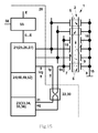
- Fig. 1 inventive excitation device for the actuator of an ultrasonic motor
- Figure 13 Actuator in multilayer design
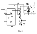
- FIG. 2 exciter device according to the invention (FIGS. 17 to 19: single and multi-phase control of the actuator)
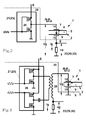
- Fig. 3-5 Embodiments of the excitation device according to the invention
- Fig. 8 equivalent circuit for the standing wave generator
- Fig. 9 frequency dependence of the currents (representation 40) and the phase differences (representation 41) of the ultrasonic wave generator of the excitation device according to the invention
- Fig. 12 Phase shift between current and voltage when changing the frequency of the excitation voltage
- FIGS. 13-17 Further embodiments of the excitation device according to the invention
- the ultrasound actuator 2 is connected by means of a friction connection or by means of a friction contact 3 to a driven element 4 which performs a linear or rotational movement.
- the actuator 2 consists of an acoustic resonator 5 designed as a plate, which however can also be designed as a disk, as a cylinder or in any other desired form which is predetermined by the construction of the ultrasonic actuator 2.
- the resonator 5 is made of piezoceramic material, but may also be made of metal, oxide ceramics, metal ceramics, a monocrystalline material or other material with high mechanical quality.
- the resonator 5 may be a closed or an open waveguide for the ultrasonic acoustic wave.
- the resonator 5 has a generator 6 for the acoustic standing wave. This is part of the resonator 5.
- the generator 6 may also represent a piezoelectric element which is connected to the resonator 5 (not shown in the figures).
- the generator 6 according to FIG. 1 has a three-layered structure, one layer being the excitation electrode 7 and one layer the general electrode 8, and a layer of piezoelectric ceramic 9 being arranged between the excitation electrode 7 and the general electrode 8.
- the polarization vector of the piezoceramic layer is oriented perpendicular to the electrodes 7, 8, as shown in representation 10 of FIG.
- the polarization vector of the piezoceramic layer is inclined relative to the electrodes 7, 8 (illustration 11 of FIG. 1) or parallel to the electrodes 7, 8 (illustration 12 of FIG. 1). Furthermore, it is conceivable that the polarization vector has different orientation in different regions of the generator 6. It is also conceivable that the polarization vector in one area has a vertical orientation, and in another section, although a vertical, but opposite orientation, i. an antiparallel alignment, has.
- the generator 6 has a multilayer structure in which the electrodes 7, 8 and the piezoceramic layer 9, as shown in representation 13 of FIG. 1, are arranged alternately.
- the different orientations of the polarization vector in the individual layers described in the previous section are conceivable.
- the standing wave generator can have strip-shaped electrodes (not shown in the figures).
- the electrodes 7 and 8 have the outputs 14, 15.
- the outputs 14, 15 are designed as a strand-like conductor, but they can also be designed as spring elements or electrically conductive rubber elements.
- the electrical capacitance C o is present.
- the generator 6 serves to generate an acoustic ultrasonic standing wave in the resonator 5, which uses the ultrasonic motor for its operation.
- This wave may be a longitudinal wave, a bending wave, a shear wave, a torsion wave, a bulk wave, a plane wave, a surface wave, a symmetrical, an asymmetrical or another acoustic wave.
- the type and shape of the wave used are determined by the geometric shape of the resonator 5, the shape of the electrodes 7 and 8, the orientation of the polarization vector of the piezoelectric ceramic with respect to the electrodes 7 and 8 and the frequency of the excitation voltage U g .
- the points of the resonator 5 at the frequency equal to the mechanical resonance frequency F m have their maximum vibration velocity V p .
- the mechanical resonance frequency F m represents the operating frequency of the ultrasonic actuator 2 and, accordingly, that of the ultrasonic motor 1. At this frequency, the ultrasonic motor 1 has optimum mechanical characteristics.
- the electrical excitation device 20 comprises a power amplifier 21, a feedback element 22, a pulse filter 23 for the voltage u g provided by the feedback element 22, and a control voltage shaping device 24.
- the power amplifier 21 is designed as a voltage changeover switch 25. In this case, the voltage switch can form a half-bridge or bridge power amplifier 26, or a two-stroke power amplifier 27.
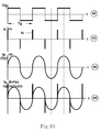
- the power amplifier 21 is fed by the DC voltage E and provides the rectangular AC voltage U g (see illustration 42 of FIG. 10).
- the outputs 14 and 15 of the electrodes 7, 8 of the acoustic wave generator 6 are connected to the power amplifier 21 via the feedback element 22.
- the pulse filter 23 has the input 31, to which the voltage u g is applied, and the output 32, to which the voltage u p is applied.
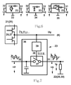
- the pulse filter 23 is constructed as a band filter 33. However, it can also be constructed as a low-pass filter 34 or as an integrator 35 (see FIG. 6). In addition, the pulse filter 23 may be a comparator or a pulse device 36 (see FIG. 7). Such a filter may include an off switch 37 for the voltage u g provided by the feedback element 22, the control input 38 of which is connected to the voltage changeover switch 21 via the edge detector 39. In addition, the pulse filter 23 may consist of passive or active electronic components or may be constructed with freely programmable microcontrollers.
- the feedback element 22 serves to convert the current I g flowing through the generator 6 into an electrical voltage u g which is proportional to this current. It is designed as a low-resistance resistor 29, but can also be realized as a measuring transformer for current-voltage 30 (see FIG. 14) or in another embodiment.
- the resonator 5 can have one or more auxiliary acoustic wave generators 16 with the electrodes 7 and 8.
- the additional generators 16 can be controlled by means of the square-wave voltage U g or with another voltage of any non-rectangular shape.
- the auxiliary generators 16 in the actuator 2 can generate an acoustic ultrasonic wave of the same type as that of the (main) generator 6; however, they may also produce an acoustic ultrasonic wave of other type than that of the (main) generator 6.
- the additional generators 16 may have the same or one of F m different mechanical resonance frequency, z. B. F z .
- the auxiliary generators 16 may have a deviating from the capacitance C o of the generator 6 capacity, z. B. C z .
- the actuator 2 can be designed to be single-phase and two-phase according to illustration 18 of FIG. A corresponding three-phase design is shown in representation 19 of FIG.
- a control with more than three phases is conceivable.
- the standing waves propagating in the actuator 2 may be pure running waves or a combination of running and standing waves.
- the outputs 14 and 15 of the electrodes 7, 8 of the standing wave generator 6 are connected to the power amplifier 21 by means of the matching transformer 28.
- FIG. 8 shows an equivalent circuit for imaging the electromechanical parameters of the standing wave generator 6 for the ultrasonic motor 1 for the range of the mechanical resonance frequency F m .
- C o electrical capacitance that forms between the electrodes 7 and 8
- L m electrical inductance, which is proportional to the mass of the actuator 2
- C m electrical capacitance which is proportional to the elastic compliance of the actuator 2
- R m electrical resistance, which is proportional to the mechanical losses in the actuator 2
- R l electrical resistance, which is proportional to the mechanical resistance of the load on the actuator 2.
- the electrical voltage U g is applied, which causes the current I g flows through the circuit. This current flows via the outputs 14, 15 and the electrodes 7, 8 of the standing wave generator 6.
- the voltage U g represents a sinusoidal voltage
- the currents I g , I c and I p (V p ) also have a sinusoidal shape.
- the amplitude of the current I g and the amplitude of the current I p (V p ) have the dependency shown in plot 40 of FIG. 9.
- the representation 41 in FIG. 9 shows the dependence of the phase shift of the voltage U g and the current I g on the frequency.
- F g is the resonance frequency of the current I g .
- the current I g has its maximum value I gm and the angle of the phase shift ⁇ g is equal to ⁇ gm .
- F m is the mechanical resonance frequency of the current I p (V p ).
- the current I p (V p ) has its maximum value I pm and the angle of the phase shift ⁇ g is equal to ⁇ pm .
- F o is the frequency at which the phase shift for the current I g is equal to zero.
- F a is the antiresonant frequency of the current I g . At the frequencies F o and F a , the phase shift angle ⁇ g is equal to zero.
- the phase shift angle ⁇ oulm is determined by the capacitance C o and the sum of the resistances R m + R l .
- the resistance R m is much smaller than the resistance R l . Therefore, a change in the resistance of the load R I results in a change in the angle ⁇ oulm for the frequency F m .
- an electric square-wave voltage U g is applied to the generator 6 of the actuator 2, the shape of which is shown in representation 42 of FIG. 10.
- the leading and trailing edges of each voltage pulse cause a fast charging and discharging of the capacitance C o .
- the charging and discharging of the capacitance C o takes place in the very short time T c , which is a multiple smaller than the period T g of the excitation voltage U g .
- This time is determined by the small resistance of the conducting transistor of the amplifier 26 and the size of the capacitance C o . Therefore, the current I c represents a series of short pulses, as can be seen from Figure 43 of FIG.
- the current pulses I c coincide in time with the edges of the pulses of the square-wave voltage U g .
- the current I c flows through the generator 6 of the piezoelectric current I p , which is proportional to the vibration velocity V p . Since the generator 6 is part of the acoustic resonator 5, the current I p has a sinusoidal shape (see illustration 44 of FIG. 10).
- the total current I g consists of the current I c and the current I p , which flows through the electrodes 7, 8 of the generator 6 (see illustration 45 of FIG. 10).
- the current I p represents an active current or active current, ie the phase shift of the current is - based on the rectangular excitation voltage U g - equals zero.
- the current I pc of the voltage U g begins to precede by the angle ⁇ p s , ie the piezoelectric current assumes a capacitive character.
- the current I pl of the voltage U g starts running after the angle ⁇ pl , ie the piezoelectric current assumes an inductive character (see also FIGS. 11, 12).
- the dependence of the phase shift of the piezoelectric current I p (V p ) on the frequency F has a smooth and unambiguous dependence over the entire range, as can be seen from illustration 47 of FIG. 11.
- the electrical excitation device 20 of the invention forms a system for regulating the frequency of the excitation voltage U g , using the stabilization of the phase shift angle between the rectangular excitation voltage U g and the piezoelectric current I p .
- the exciter device 20 may be a positive feedback autogenerator, where at the frequency F m, the phase shift angle in the feedback loop is zero and the gain coefficient is greater than one.
- the control voltage shaping device 24 is implemented as a limiting amplifier 48 (see FIG. 13).
- the exciter device 20 may also be a PLL system for negative feedback frequency control.
- the control voltage shaping device 24 consists of a phase detector 49 with a reference input 50 and a measuring input 51 and a controlled generator 52 (see FIG. 14).
- the electrical excitation device 20 comprises a symmetrical PWM modulator 53 with a control input 54, the excitation voltage U g representing a width-modulated square-wave voltage.
- FIG. 15 shows an electrical excitation device 20, which contains a regulator 15 for the electrical supply voltage E, which represents the voltage supply for the power amplifier 21 with a control input 56.
- This controller 55 may, for. B. be designed as a DC-DC converter, which operates like a PWM modulator.
- the 16 shows a variant of the electrical excitation device 20, which has a stabilization system 57 for the piezoelectric current I p flowing through the standing wave generator 6.
- the stabilization system 57 has a measuring input 58 connected to the output 32 of the pulse filter 23.
- Fig. 17 shows an electrical excitation device 20 in which the function of the electrical members pulse filter 23, control voltage shaping device 24, bandpass filter 33, lowpass filter 34, integrator 35, pulse device 36, phase detector 49, controlled generator 52 and stabilization system 57 is partially or completely replaced by one programmed digital processor of the type DSP or FPGA.
- the digital processor 59 may include the interface port 60.
- the voltage u P which is proportional to the piezoelectric current I p
- the voltage u c which is proportional to the charging and discharging current I c of the capacitance C o , separated.
- the frequency F of the rectangular excitation voltage U g is changed so that the phase shift ⁇ p between the piezoelectric current I p and the rectangular excitation voltage U g approaches zero or becomes zero.
- the piezoelectric current I p flowing through the generator 6 for the acoustic standing wave of the actuator 2 can be stabilized in this case.
- the electrical excitation device 20 functions as follows: when the supply voltage E is applied, the power amplifier 21 (25, 26, 27) provides a rectangular electrical excitation voltage U g whose frequency F is slightly different from that of the mechanical resonance frequency F m of the Aktors 2 differentiates. This voltage is applied to the outputs 14, 15 of the electrodes 7, 8 of the generator 6. The voltage causes the current I g to start to flow through the generator 6 and the feedback element 22 (29, 30). At the feedback element 22 (29, 30) appears the voltage u g , which is proportional to the current I g .
- the voltage u p is separated from the voltage u g , whereby u p proportional to the piezoelectric current I p and u c are proportional to the charging and discharging current I c of the capacitance C o behaves.
- the voltage u p represents a sinusoidal voltage whose phase in the mechanical resonance frequency F m coincides with the phase of the rectangular excitation voltage U g (or is rotated by 180 °).
- the frequency-phase characteristic of the voltage u p represents - based on the Rechteckerregerêt U g - a smooth and unique dependence.
- the electrical excitation device 20 is designed as an autogenerator, when the supply voltage E is switched on by the generator 6, a pulse current flows, so that a vibration process with the mechanical resonance frequency F m starts as a result in the electrical exciter device 20. Since at the mechanical resonance frequency F m the phase shift angle related to the feedback element 22 is zero and this angle does not depend on the load on the actuator, the electrical excitation device 20 oscillates at any load on the actuator 2 at the mechanical resonance frequency F m .
- the electrical excitation device 20 When the electrical excitation device 20 is a PLL system for negative feedback frequency control, this system stabilizes the phase shift angle ⁇ p between the rectangular electric voltage u g and the voltage u p , ie, the piezoelectric current I p to be zero. In this case, the electrical excitation device 20 provides the voltage U g , whose frequency at any load on the actuator 2 is always equal to the mechanical resonance frequency F m .
- the additional stabilization of the piezoelectric current I p with the aid of the stabilization system 57 makes it possible to additionally stabilize the oscillation speed V p , and thus also the speed of movement of the element 4 to be driven.
- half-bridge or bridge amplifiers 26 or two-stroke power amplifiers 27 it is possible to reduce the internal resistance of the voltage changeover switch 25 to a maximum and thus to shorten the pulse duration t c of the capacitive current I c to a maximum.
- the implementation of the pulse filter 23 as a band filter 33 makes it possible to eliminate the phase error at the mechanical resonance frequency F m , while the design of the pulse filter 23 as a low-pass filter 34 or as an integrator 35 makes it possible to build these filters extremely simple.
- the pulse filter 23 As a pulse device 36, it is possible to eliminate the phase error in the entire operating frequency range of the excitation device 20.
- the design of the electronic members as a digital processor 59 makes it possible to simplify the electrical excitation device 20 and its structure, reduce its cost and increase its immunity to interference.
- the inventive method and the device according to the invention make it possible to optimally keep the frequency of the excitation voltage for the ultrasonic actuator. This frequency is kept constant regardless of the forces acting on the actuator of the ultrasonic motor loads equal to the mechanical resonance frequency of the actuator. This increases the operational stability of the ultrasonic motor. The fact that the ultrasonic motor always operates in an optimal operating regime, the amount of excitation voltage is reduced, and the current required for operation or the power required for operation are reduced. The engine heats up less, which extends its temperature range.
Landscapes
- General Electrical Machinery Utilizing Piezoelectricity, Electrostriction Or Magnetostriction (AREA)
Priority Applications (3)
| Application Number | Priority Date | Filing Date | Title |
|---|---|---|---|
| US13/877,235 US9479088B2 (en) | 2010-10-01 | 2011-09-28 | Method and device for electrically exciting an actuator for an ultrasonic motor |
| EP11813663.9A EP2622726B1 (de) | 2010-10-01 | 2011-09-28 | Verfahren und vorrichtung zur elektrischen erregung eines aktors für einen ultraschallmotor |
| JP2013530567A JP5833658B2 (ja) | 2010-10-01 | 2011-09-28 | 超音波モータのためのアクチュエータを電気的に励起する方法及び装置 |
Applications Claiming Priority (2)
| Application Number | Priority Date | Filing Date | Title |
|---|---|---|---|
| DE102010047280A DE102010047280A1 (de) | 2010-10-01 | 2010-10-01 | Verfahren und Vorrichtung zur elektrischen Erregung eines Aktors für einen Ultraschallmotor |
| DE102010047280.8 | 2010-10-01 |
Publications (2)
| Publication Number | Publication Date |
|---|---|
| WO2012048691A2 true WO2012048691A2 (de) | 2012-04-19 |
| WO2012048691A3 WO2012048691A3 (de) | 2012-05-24 |
Family
ID=45540689
Family Applications (1)
| Application Number | Title | Priority Date | Filing Date |
|---|---|---|---|
| PCT/DE2011/050037 Ceased WO2012048691A2 (de) | 2010-10-01 | 2011-09-28 | Verfahren und vorrichtung zur elektrischen erregung eines aktors für einen ultraschallmotor |
Country Status (5)
| Country | Link |
|---|---|
| US (1) | US9479088B2 (enExample) |
| EP (1) | EP2622726B1 (enExample) |
| JP (1) | JP5833658B2 (enExample) |
| DE (1) | DE102010047280A1 (enExample) |
| WO (1) | WO2012048691A2 (enExample) |
Cited By (1)
| Publication number | Priority date | Publication date | Assignee | Title |
|---|---|---|---|---|
| WO2025086581A1 (zh) * | 2023-10-26 | 2025-05-01 | 南京航达超控科技有限公司 | 一种超声电机孤极归一化整定电路 |
Families Citing this family (4)
| Publication number | Priority date | Publication date | Assignee | Title |
|---|---|---|---|---|
| EP2960522A1 (en) * | 2014-06-27 | 2015-12-30 | Alcatel Lucent | Apparatus and method for operating an oscillation blade device and a system comprising the apparatus |
| US10883486B1 (en) * | 2017-11-21 | 2021-01-05 | Huilin Zhou | Forced surface traveling wave-driven microfluidic pump |
| KR20210155633A (ko) | 2020-06-16 | 2021-12-23 | 엘지이노텍 주식회사 | 초음파 리니어 모터 및 이의 구동 방법 |
| CN115040200B (zh) * | 2022-05-20 | 2023-11-03 | 以诺康医疗科技(苏州)有限公司 | 超声手术工具、其频率跟踪方法、其目标相位差确定方法及超声波换能器等效电路 |
Citations (4)
| Publication number | Priority date | Publication date | Assignee | Title |
|---|---|---|---|---|
| US5214339A (en) | 1990-07-04 | 1993-05-25 | Asmo Co., Ltd. | Circuit and method of driving an ultrasonic motor to method for driving an ultrasonic motor |
| US5461273A (en) | 1992-12-16 | 1995-10-24 | Matsushita Electric Industrial Co., Ltd. | Method and an apparatus for controlling a moving velocity of an ultrasonic motor |
| US5479063A (en) | 1990-02-14 | 1995-12-26 | Nikon Corporation | Driving device for ultrasonic wave motor |
| US5872418A (en) | 1994-10-31 | 1999-02-16 | Pi Ceramic Gmbh | Piezoelectric motor |
Family Cites Families (14)
| Publication number | Priority date | Publication date | Assignee | Title |
|---|---|---|---|---|
| JP4499877B2 (ja) * | 2000-06-13 | 2010-07-07 | セイコーインスツル株式会社 | 超音波モータおよび超音波モータ付き電子機器 |
| US7218029B2 (en) * | 2001-05-22 | 2007-05-15 | Texas Instruments Incorporated | Adjustable compensation of a piezo drive amplifier depending on mode and number of elements driven |
| US6794795B2 (en) * | 2001-12-19 | 2004-09-21 | Caterpillar Inc | Method and apparatus for exciting a piezoelectric material |
| DE10218565A1 (de) * | 2002-04-26 | 2003-11-06 | Philips Intellectual Property | Startprozess-Steuerung für den Anlauf eines Piezomotors |
| US7287965B2 (en) * | 2004-04-02 | 2007-10-30 | Adaptiv Energy Llc | Piezoelectric devices and methods and circuits for driving same |
| DE102005039358B4 (de) * | 2005-08-19 | 2016-12-08 | Physik Instrumente (Pi) Gmbh & Co. Kg | Piezoelektrischer Aktor für einen Ultraschallmotor |
| DE102006042695B4 (de) * | 2006-01-18 | 2012-02-23 | Physik Instrumente (Pi) Gmbh & Co. Kg | Selbsterregender PWM-Controller für einen Einphasenultraschallmotor |
| DE102006025991B4 (de) * | 2006-06-02 | 2012-02-23 | Physik Instrumente (Pi) Gmbh & Co. Kg | Selbsterregender Niederspannungscontroller zur Steuerung eines oder mehrerer Ultraschallmikromotoren |
| DE102006054597B4 (de) * | 2006-11-20 | 2012-03-01 | Physik Instrumente (Pi) Gmbh & Co. Kg | Steuervorrichtung eines Ultraschallmotors |
| DE102007016642B4 (de) * | 2007-04-05 | 2015-12-17 | Austriamicrosystems Ag | Elektromechanisches System und Verfahren zum Betrieb eines elektromechanischen Systems |
| DE102008012992A1 (de) * | 2008-03-07 | 2009-09-10 | Physik Instrumente (Pi) Gmbh & Co. Kg | Ultraschallmotor |
| IT1393824B1 (it) * | 2009-04-20 | 2012-05-11 | Zobele Holding Spa | Atomizzatore di liquidi con dispositivo di vibrazione piezoelettrico a circuito elettronico di controllo perfezionato e relativo metodo di azionamento. |
| CN102025339B (zh) * | 2009-09-18 | 2014-07-16 | 株式会社村田制作所 | 压电致动器驱动电路 |
| WO2011090780A1 (en) * | 2010-01-20 | 2011-07-28 | Northwestern University | Method and apparatus for increasing the forces applied to bare a finger on a haptic surface |
-
2010
- 2010-10-01 DE DE102010047280A patent/DE102010047280A1/de not_active Withdrawn
-
2011
- 2011-09-28 JP JP2013530567A patent/JP5833658B2/ja active Active
- 2011-09-28 US US13/877,235 patent/US9479088B2/en active Active
- 2011-09-28 WO PCT/DE2011/050037 patent/WO2012048691A2/de not_active Ceased
- 2011-09-28 EP EP11813663.9A patent/EP2622726B1/de active Active
Patent Citations (4)
| Publication number | Priority date | Publication date | Assignee | Title |
|---|---|---|---|---|
| US5479063A (en) | 1990-02-14 | 1995-12-26 | Nikon Corporation | Driving device for ultrasonic wave motor |
| US5214339A (en) | 1990-07-04 | 1993-05-25 | Asmo Co., Ltd. | Circuit and method of driving an ultrasonic motor to method for driving an ultrasonic motor |
| US5461273A (en) | 1992-12-16 | 1995-10-24 | Matsushita Electric Industrial Co., Ltd. | Method and an apparatus for controlling a moving velocity of an ultrasonic motor |
| US5872418A (en) | 1994-10-31 | 1999-02-16 | Pi Ceramic Gmbh | Piezoelectric motor |
Cited By (1)
| Publication number | Priority date | Publication date | Assignee | Title |
|---|---|---|---|---|
| WO2025086581A1 (zh) * | 2023-10-26 | 2025-05-01 | 南京航达超控科技有限公司 | 一种超声电机孤极归一化整定电路 |
Also Published As
| Publication number | Publication date |
|---|---|
| EP2622726A2 (de) | 2013-08-07 |
| US20130307440A1 (en) | 2013-11-21 |
| JP2013539346A (ja) | 2013-10-17 |
| DE102010047280A1 (de) | 2012-04-05 |
| US9479088B2 (en) | 2016-10-25 |
| JP5833658B2 (ja) | 2015-12-16 |
| WO2012048691A3 (de) | 2012-05-24 |
| EP2622726B1 (de) | 2016-03-09 |
Similar Documents
| Publication | Publication Date | Title |
|---|---|---|
| EP2622726B1 (de) | Verfahren und vorrichtung zur elektrischen erregung eines aktors für einen ultraschallmotor | |
| EP2711093B1 (de) | Ultraschall-Generator mit ausgangsseitigem Tiefpass | |
| DE60309725T2 (de) | Wellenformgenerator-elektronik mit abgestimmten lc-schaltkreisen | |
| DE69229289T2 (de) | Treiberschaltung für Vibrationsmotor | |
| DE69516908T2 (de) | Antriebsverfahren für einen Ultraschallmotor | |
| EP2497129B1 (de) | Aktuator | |
| EP2845305B1 (de) | Ultraschallmotor | |
| DE2530045A1 (de) | Elektrischer motor | |
| DE10158584A1 (de) | Piezoelektrische Antriebsvorrichtung und ein Regelverfahren für eine piezoelektrische Antriebsvorrichtung | |
| WO2017016853A1 (de) | Verfahren zur frequenzregelung eines piezoelektrischen transformators sowie schaltungsanordnung mit einem piezoelektrischen transformator | |
| DE10329863B9 (de) | Piezokeramischer Wellenantriebs-Ultraschallwellenmotor | |
| DE2916540A1 (de) | Elektrische schaltungsanordnung zur ansteuerung eines piezoelektrischen wandlers | |
| DE102011087542B3 (de) | Zweiphasen-Ultraschallmotor | |
| DE102010028007A1 (de) | Wandler mit natürlicher Unidirektionalität für akustische Oberflächenwellen | |
| EP2979311A1 (de) | Schaltungsanordnung und verfahren zur ansteuerung eines piezotransformators | |
| DE102006042695B4 (de) | Selbsterregender PWM-Controller für einen Einphasenultraschallmotor | |
| DE102013203836B4 (de) | Piezoelektrisches Ultraschall-Vibrationselement und seine Verwendung | |
| DE102011108175A1 (de) | Ansteuerschaltung für Ultraschallmotoren | |
| AT521100A1 (de) | Wechselrichter mit Zwischenkreis | |
| WO2007028784A1 (de) | Schaltung und verfahren zur ansteuerung eines piezoelektrischen oder elektrostriktiven aktors | |
| WO2022122436A2 (de) | Effizienter antrieb für piezoelektrische trägheitsmotoren | |
| DE102021121352B3 (de) | Aktuator | |
| EP2710725B1 (de) | Inverter | |
| DE3040916C2 (de) | Piezo-Zündeinrichtung für Thyristoren und Triacs | |
| DE2143103C3 (enExample) |
Legal Events
| Date | Code | Title | Description |
|---|---|---|---|
| 121 | Ep: the epo has been informed by wipo that ep was designated in this application |
Ref document number: 11813663 Country of ref document: EP Kind code of ref document: A2 |
|
| ENP | Entry into the national phase |
Ref document number: 2013530567 Country of ref document: JP Kind code of ref document: A |
|
| WWE | Wipo information: entry into national phase |
Ref document number: 2011813663 Country of ref document: EP |
|
| WWE | Wipo information: entry into national phase |
Ref document number: 13877235 Country of ref document: US |