EP2622726B1 - Verfahren und vorrichtung zur elektrischen erregung eines aktors für einen ultraschallmotor - Google Patents
Verfahren und vorrichtung zur elektrischen erregung eines aktors für einen ultraschallmotor Download PDFInfo
- Publication number
- EP2622726B1 EP2622726B1 EP11813663.9A EP11813663A EP2622726B1 EP 2622726 B1 EP2622726 B1 EP 2622726B1 EP 11813663 A EP11813663 A EP 11813663A EP 2622726 B1 EP2622726 B1 EP 2622726B1
- Authority
- EP
- European Patent Office
- Prior art keywords
- voltage
- current
- actuator
- electrical
- piezoelectric
- Prior art date
- Legal status (The legal status is an assumption and is not a legal conclusion. Google has not performed a legal analysis and makes no representation as to the accuracy of the status listed.)
- Active
Links
- 238000000034 method Methods 0.000 title claims description 21
- 230000005284 excitation Effects 0.000 claims description 77
- 230000010363 phase shift Effects 0.000 claims description 22
- 238000007599 discharging Methods 0.000 claims description 12
- 238000007493 shaping process Methods 0.000 claims description 8
- 230000006641 stabilisation Effects 0.000 claims description 6
- 238000011105 stabilization Methods 0.000 claims description 6
- 238000000926 separation method Methods 0.000 claims 2
- 238000005259 measurement Methods 0.000 claims 1
- 230000010287 polarization Effects 0.000 description 7
- 230000033001 locomotion Effects 0.000 description 5
- 239000000919 ceramic Substances 0.000 description 4
- 239000000463 material Substances 0.000 description 3
- 230000010355 oscillation Effects 0.000 description 3
- 230000000087 stabilizing effect Effects 0.000 description 3
- 238000013459 approach Methods 0.000 description 2
- 238000006243 chemical reaction Methods 0.000 description 2
- 238000010276 construction Methods 0.000 description 2
- 230000001687 destabilization Effects 0.000 description 2
- 230000036039 immunity Effects 0.000 description 2
- 239000002184 metal Substances 0.000 description 2
- 238000002604 ultrasonography Methods 0.000 description 2
- 230000004913 activation Effects 0.000 description 1
- 238000005452 bending Methods 0.000 description 1
- 230000009286 beneficial effect Effects 0.000 description 1
- 230000033228 biological regulation Effects 0.000 description 1
- 239000004020 conductor Substances 0.000 description 1
- 230000001419 dependent effect Effects 0.000 description 1
- 230000000368 destabilizing effect Effects 0.000 description 1
- 230000001627 detrimental effect Effects 0.000 description 1
- 238000006073 displacement reaction Methods 0.000 description 1
- 238000010438 heat treatment Methods 0.000 description 1
- 230000001939 inductive effect Effects 0.000 description 1
- 238000013507 mapping Methods 0.000 description 1
- 239000011224 oxide ceramic Substances 0.000 description 1
- 229910052574 oxide ceramic Inorganic materials 0.000 description 1
- 230000001902 propagating effect Effects 0.000 description 1
- 230000001105 regulatory effect Effects 0.000 description 1
Images


Classifications
-
- H—ELECTRICITY
- H02—GENERATION; CONVERSION OR DISTRIBUTION OF ELECTRIC POWER
- H02N—ELECTRIC MACHINES NOT OTHERWISE PROVIDED FOR
- H02N2/00—Electric machines in general using piezoelectric effect, electrostriction or magnetostriction
- H02N2/02—Electric machines in general using piezoelectric effect, electrostriction or magnetostriction producing linear motion, e.g. actuators; Linear positioners ; Linear motors
- H02N2/06—Drive circuits; Control arrangements or methods
-
- H—ELECTRICITY
- H02—GENERATION; CONVERSION OR DISTRIBUTION OF ELECTRIC POWER
- H02N—ELECTRIC MACHINES NOT OTHERWISE PROVIDED FOR
- H02N2/00—Electric machines in general using piezoelectric effect, electrostriction or magnetostriction
- H02N2/0005—Electric machines in general using piezoelectric effect, electrostriction or magnetostriction producing non-specific motion; Details common to machines covered by H02N2/02 - H02N2/16
- H02N2/0075—Electrical details, e.g. drive or control circuits or methods
- H02N2/008—Means for controlling vibration frequency or phase, e.g. for resonance tracking
Definitions
- the present invention relates to a method and a device for the electrical excitation of an actuator for an ultrasonic motor.
- the disadvantage of this method and the corresponding exciter device is that the phase difference between the electrical excitation voltage of the actuator and the voltage of the auxiliary electrode depends on the mechanical load on the actuator. Therefore, in the case of high mechanical loads on the ultrasonic actuator in these motors, the frequency of the excitation electric voltage is not equal to the mechanical resonance frequency of the ultrasonic actuator. This has a destabilizing effect on the function of the ultrasonic motor.
- the auxiliary electrode must have a large area for safe operation, which in turn reduces the area for the excitation electrodes and causes an increase in the excitation voltage.
- the auxiliary electrode must have an additional output in the form of a thin wire. At high moving speeds of the movable element, this reduces the reliability of the motors.
- the disadvantage of this method is also that the phase difference between the electrical excitation voltage and the current flowing through the piezoelectric element depends on the mechanical load on the ultrasonic actuator. This is due to the fact that the sinusoidal current flowing through the piezoelectric element has two components, namely a capacitive current flowing through the electrical capacitance of the piezoelectric element, and a piezoelectric current, which is determined by the angle of rotation of the domains of the piezoelectric element. At the mechanical resonance frequency, the piezoelectric current represents a so-called active current or active current. With a small mechanical load on the ultrasonic actuator, the active resistance of the actuator is significantly smaller than its reactive resistance.
- the phase shift between the excitation voltage and the current flowing through the piezoelectric element is small at the mechanical resonance frequency and approaches zero.
- Increasing the mechanical load applied to the actuator increases the active resistance, while the reactive resistance remains constant. Therefore, the increase in the mechanical load causes an increase in the displacement angle between the excitation voltage and the current flowing through the piezoelectric element of the ultrasonic actuator.
- the phase shift angle of a few degrees may increase ten times or more as the mechanical load increases.
- the oscillations of the phase shift are caused not only by a mechanical load on the driven element, but also by a ripple of the Fritationsoberflache and by a mechanical imbalance of the driven element.
- This destabilization causes the excitation voltage to increase and the required current and power to increase.
- speed oscillations of the element to be driven occur.
- the maximum force that can be generated by the engine is reduced. This force depends on the position of the element to be driven.
- the motor can come to a standstill and the actuator heat up. By means of said heating, the temperature range of use for the ultrasonic motor narrows.
- the basic idea of the invention is to separate the piezoelectric current flowing through the actuator from the capacitive charging current of the actuator and to use the phase shift of the separated piezoelectric current for the regulation of the frequency of the excitation voltage of the ultrasonic actuator.
- the invention provides a method for electrically exciting an actuator for an ultrasonic motor having a mechanical resonance frequency F m , the ultrasonic motor comprising at least one standing wave acoustic wave generator comprising an excitation electrode and a general electrode, wherein between the excitation electrode and the general electrode has an electrical capacitance C 0 trains.
- the method according to the invention in a first step, the application of a rectangular exciter voltage U g to the excitation electrode and the general electrode of the at least one standing wave acoustic generator, wherein the frequency of the rectangular excitation voltage differs from the mechanical resonance frequency F m of the actuator.
- an electrical voltage U g is provided, wherein the electrical voltage U g is proportional to a current flowing through the standing wave generator current I g , and the current I g is a sum current of a piezoelectric current I g and a charging and discharging I e of the electrical capacitance C 0 is.
- This is followed by the step of separating an electrical voltage U p from the electrical voltage U e by means of a pulse filter, wherein the electrical voltage U p proportional to the piezoelectric current I p and the electrical voltage U e proportional to the charging and discharging current I e of the electric Capacitance C is 0 .
- the frequency of the rectangular excitation voltage is changed so that the phase shift between the piezoelectric current I p and the rectangular excitation voltage U g is substantially zero.
- An inventive device for the electrical excitation of a piezoelectric actuator of an ultrasonic motor wherein the actuator comprises at least one acoustic standing wave generator comprises at least one power amplifier, a feedback element, a filter and a control voltage forming device.
- the at least one power amplifier is designed as a voltage switch for a supply voltage of the actuator, wherein the voltage switch is connected to the at least one acoustic standing wave generator directly or indirectly.
- the feedback element is in series is switched with the standing wave acoustic wave generator, so that flows through this the same current as through the standing wave generator, and the filter is designed as a pulse filter of the electrical voltage generated by the feedback element executed.
- an output of the filter is connected to an input of the control voltage forming means and the control voltage forming means is connected to an input of the at least one power amplifier.
- the method according to the invention and the device according to the invention make it possible to keep the optimum frequency of the exciter voltage for the ultrasound actuator.
- This frequency is kept constant regardless of the forces acting on the actuator of the ultrasonic motor loads equal to the mechanical resonance frequency of the actuator, thereby increasing the operating stability of the ultrasonic motor.
- the ultrasonic motor always works in an optimal operating regime. This reduces the excitation voltage level, reduces the required current and power, and less heats the motor.
- the piezoelectric current I p flowing through the standing wave generator is additionally stabilized.
- the oscillation speed of the shaft generated in the actuator and thus also the speed of movement of the element to be driven can be additionally stabilized.
- the voltage changeover switch is designed as a half-bridge power amplifier or as a bridge power amplifier or as a two-stroke power amplifier. This makes it possible to significantly reduce the internal resistance of the voltage switch and thus to shorten the pulse duration of the capacitive charging and discharging current I e maximum.
- the feedback element may comprise a low-impedance active resistance or a measuring transformer for an electric current. As a result, the phase error in the conversion of the current I g in the voltage U g be significantly reduced.
- the pulse filter may be designed as a band filter tuned to the mechanical resonance frequency Fm of the actuator for the voltage generated by the feedback element.
- the execution of the pulse filter 23 as the band filter 33 makes it possible to eliminate the phase error at the mechanical resonance frequency F m .
- the pulse filter is designed as a low-pass filter or as an integrator for the voltage generated by the feedback element. This achieves an extremely simple construction of the pulse filter.
- the pulse filter comprises an off switch for the voltage generated by the feedback element, and a control input of the off switch is connected via an edge detector with the voltage switch.
- the pulse filter is designed as a voltage comparator.
- the device for electrical excitation of a piezoelectric actuator of an ultrasonic motor is designed as an autogenerator.
- control voltage forming device may comprise a phase detector and a controlled generator for a square-wave voltage.
- control voltage forming device may also comprise a symmetrical PWM modulator.
- a symmetrical PWM modulator it is possible to regulate the current I p and thus the speed of movement of the element to be driven.
- the device for electrical excitation of a piezoelectric actuator of an ultrasonic motor a controller for the electrical voltage that powers the power amplifier has. This also makes it possible to regulate the current I p and thus the speed of movement of the element to be driven.
- the device for electrical excitation of a piezoelectric actuator of an ultrasonic motor has a stabilizing system for the piezoelectric current flowing through the standing wave generator.
- the electronic elements of the device for the electrical excitation of a piezoelectric actuator of an ultrasonic motor partially or completely by a programmable digital processor of the type DSP (Digital Signal Processor or Digital Signal Processor) or FPGA (Field Programmable Gate Array) are realized.
- DSP Digital Signal Processor or Digital Signal Processor
- FPGA Field Programmable Gate Array
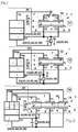
- Fig. 1 shows an excitation device according to the invention for an ultrasonic actuator 2 of an ultrasonic motor 1.
- the ultrasonic actuator 2 by means of a FritationsENS or by means of a Fritationsplayers 3 with a driven element 4, which performs a linear or rotary motion connected.
- the actuator 2 consists of an acoustic resonator 5 designed as a plate, which however can also be designed as a disk, as a cylinder or in any other desired form which is predetermined by the construction of the ultrasonic actuator 2.
- the resonator 5 is made of piezoceramic material, but may also be made of metal, oxide ceramics, metal ceramics, a monocrystalline material or other material with high mechanical quality.
- the resonator 5 may be a closed or an open waveguide for the ultrasonic acoustic wave.
- the resonator 5 has a generator 6 for the acoustic standing wave. This is part of the resonator 5.
- the generator 6 may also represent a piezoelectric element which is connected to the resonator 5 (not shown in the figures).
- the generator 6 according to Fig. 1 has a three-layered structure, wherein one layer is the excitation electrode 7 and one layer is the general electrode 8, and between the excitation electrode 7 and the common electrode 8, a layer of piezoelectric ceramic 9 is arranged.
- the polarization vector of Piezoceramic layer is oriented perpendicular to the electrodes 7, 8, as shown in FIG. 10 of FIG Fig. 1 is shown.
- the polarization vector of the piezoceramic layer inclined to the electrodes 7, 8 (representation 11 of Fig. 1 ) or parallel to the electrodes 7, 8 (illustration 12 of FIG Fig. 1 ) is aligned.
- the polarization vector has different orientation in different regions of the generator 6.
- the polarization vector has a vertical orientation in one area, and although in another section, likewise has a vertical, but opposite orientation, ie an antiparallel orientation.
- the generator 6 it is possible for the generator 6 to have a multilayer structure in which the electrodes 7, 8 and the piezoceramic layer 9, as shown in FIG Fig. 1 shown, are arranged alternately.
- the different orientations of the polarization vector in the individual layers described in the previous section are conceivable.
- the standing wave generator can have strip-shaped electrodes (not shown in the figures).
- the electrodes 7 and 8 have the outputs 14, 15.
- the outputs 14, 15 are designed as a strand-like conductor, but they can also be designed as spring elements or electrically conductive rubber elements.
- the generator 6 serves to generate an acoustic ultrasonic standing wave in the resonator 5, which uses the ultrasonic motor for its operation.
- This wave may be a longitudinal wave, a bending wave, a shear wave, a torsion wave, a bulk wave, a plane wave, a surface wave, a symmetrical, an asymmetrical or another acoustic wave.
- the points of the resonator 5 at the frequency equal to the mechanical resonance frequency F m have their maximum vibration velocity v p .
- the mechanical resonance frequency F m represents the operating frequency of the ultrasonic actuator 2 and, accordingly, that of the ultrasonic motor 1. At this frequency, the ultrasonic motor 1 has optimum mechanical characteristics.
- the electrical excitation device 20 comprises a power amplifier 21, a feedback element 22, a pulse filter 23 for the voltage U g provided by the feedback element 22, and a control voltage forming device 24.
- the power amplifier 21 is designed as a voltage changeover switch 25. In this case, the voltage switch can form a half-bridge or bridge power amplifier 26, or a two-stroke power amplifier 27.
- the power amplifier 21 is fed by the DC voltage E and provides the rectangular AC voltage U g (see illustration 42 of FIG Fig. 10 ) ready.
- the outputs 14 and 15 of the electrodes 7, 8 of the acoustic wave generator 6 are connected to the power amplifier 21 via the feedback element 22.
- the pulse filter 23 has the input 31, to which the voltage U g is applied, and the output 32, at which the voltage is applied up.
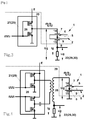
- the pulse filter 23 is constructed as a band filter 33. However, it can also be used as a low-pass filter 34 or as an integrator 35 (see Fig. 6 ) be constructed. In addition, the pulse filter 23, a comparator or a pulse device 36 (see Fig. 7 ) be. Such a filter may include an off switch 37 for the voltage U g provided by the feedback element 22, the control input 38 of which is connected to the voltage switch 21 via the edge detector 39. In addition, the pulse filter 23 may consist of passive or active electronic components or may be constructed with freely programmable microcontrollers.
- the feedback element 22 serves to convert the current I g flowing through the generator 6 into a power proportional to this current electrical voltage U g . It is designed as a low-resistance resistor 29, but can also be used as a measuring transformer for current-voltage 30 (see Fig. 14 ) or realized in another embodiment.
- the resonator 5 may have one or more auxiliary acoustic wave generators 16 with the electrodes 7 and 8.
- the additional generators 16 can be controlled by means of the square-wave voltage U g or with another voltage of any non-rectangular shape.
- the auxiliary generators 16 in the actuator 2 can generate an acoustic ultrasonic wave of the same type as that of the (main) generator 6; however, they may also produce an acoustic ultrasonic wave of other type than that of the (main) generator 6.
- the additional generators 16 may have the same or one of Fm different mechanical resonance frequency, z. B. F z .
- the additional generators 16 may have a deviating from the capacitance Co of the generator 6 capacity, z. B. C z .
- FIG. 19 Fig. 2 shown.
- a control with more than three phases is conceivable.
- the standing waves propagating in the actuator 2 may be pure running waves or a combination of running and standing waves.
- the outputs 14 and 15 of the electrodes 7, 8 of the standing wave generator 6 are connected to the power amplifier 21 by means of the matching transformer 28.
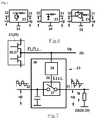
- Fig. 8 shows an equivalent circuit for mapping the electromechanical parameters of the standing wave generator 6 for the ultrasonic motor 1 for the range of the mechanical resonance frequency F m .
- Co electrical capacitance which forms between the electrodes 7 and 8
- L m electrical Inductance, which is proportional to the mass of the actuator 2
- C m electrical capacitance which is proportional to the elastic compliance of the actuator 2
- R m electrical resistance, which is proportional to the mechanical losses in the actuator 2
- R 1 electrical resistance, which is proportional to the mechanical resistance of the load on the actuator 2.
- the electrical voltage U g is applied, which causes the current I g flows through the circuit. This current flows via the outputs 14, 15 and the electrodes 7, 8 of the standing wave generator 6.
- the voltage U g represents a sinusoidal voltage
- the currents I g , I e and I p (vp) also have a sinusoidal shape.
- the amplitude of the current I g and the amplitude of the current I p (v p ) in the representation 40 of Fig. 9 illustrated dependency.
- the illustration 41 in Fig. 9 shows the dependence of the phase shift of the voltage U g and the current I p of the frequency.
- F g is the resonance frequency of the current I g .
- the current Ig has its maximum value Igm and the angle of the phase shift CPg is equal to cpgm.
- Fm is the mechanical resonance frequency of the current Ip (Vp).
- the current I p (v p ) has its maximum value I pm and the angle of the phase shift ⁇ g is equal to ⁇ pm .
- F 0 is the frequency at which the phase shift for the current I g is zero.
- Fa is the antiresonant frequency of the current I g .
- the phase shift angle ⁇ g is equal to zero.
- the phase shift angle ⁇ pm is determined by the capacitance C 0 and the sum of the resistances Rm + R1.
- the resistance R m is much smaller than the resistance R j . Therefore, a change in the resistance of the load R j results in a change in the angle ⁇ pm for the frequency F m .
- an electric square-wave voltage U g is applied to the generator 6 of the actuator 2, whose shape in representation 42 of the Fig. 10 is shown.
- the leading and trailing edges of each voltage pulse cause a fast charging and discharging of the capacitance C 0 .
- the charging and discharging of the capacitance C 0 takes place in the very short time T e , which is a multiple smaller than the period Tg of the excitation voltage U g .
- This time is determined by the small resistance of the conducting transistor of the amplifier 26 and the size of the capacitance C 0 . Therefore, the current I e represents a series of short pulses, as shown in Figure 43 of the Fig. 10 can be seen.
- the current pulses I e coincide in time with the hanks of the pulses of the square-wave voltage U g .
- the current I e flows through the generator 6 of the piezoelectric current Ip, which is proportional to the vibration velocity V p . Since the generator 6 is part of the acoustic resonator 5, the current I p has a sinusoidal shape (see Illustration 44 of Fig. 10 ).
- the total current I g consists of the current I e and the current I p , through the electrodes 7, 8 of the generator 6 (see illustration 45 of Fig. 10 ) flows.
- the current I p is an active current or active current, ie the phase shift of the current is - based on the rectangular excitation voltage U g - equal to zero ,
- the current Ipe of the voltage U g begins to precede by the angle ⁇ pc , ie the piezoelectric current assumes a capacitive character.
- the current Ipj of the voltage U g begins to run behind the angle ⁇ p1 , ie the piezoelectric current assumes an inductive character (see also Fig. 11, 12th ).
- the dependence of the phase shift of the piezoelectric current I p (V p ) on the frequency F has a smooth and unambiguous dependence over the entire range, as shown in FIG Fig. 11 seen.
- the electrical excitation device 20 of the invention forms a system for regulating the frequency of the excitation voltage U g , using the stabilization of the phase shift angle between the rectangular excitation voltage U g and the piezoelectric current I p .
- the exciter device 20 may be a positive feedback autogenerator, where at the frequency F m, the phase shift angle in the feedback loop is zero and the gain coefficient is greater than one.
- the control voltage shaping device 24 is designed as a limiting amplifier 48 (see Fig. 13 ).
- the exciter device 20 may also be a PLL system for negative feedback frequency control.
- the control voltage forming means 24 consists of a phase detector 49 having a reference input 50 and a measuring input 51 and a controlled generator 52 (see Fig. 14 ).
- the electrical excitation device 20 comprises a symmetrical PWM modulator 53 with a control input 54, the excitation voltage U g representing a width-modulated square-wave voltage.
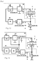
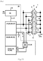
- Fig. 15 1 shows an electrical excitation device 20, which contains a regulator 15 for the electrical supply voltage E, which represents the voltage supply for the power amplifier 21 with a control input 56.
- This regulator 55 can be designed, for example, as a DC-DC converter, which operates like a PWM modulator.
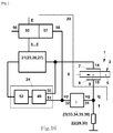
- Fig. 16 shows a variant of the electrical excitation device 20, which has a stabilizing system 57 for the flowing through the standing wave generator 6 piezoelectric current I p .
- the stabilization system 57 has a measuring input 58 connected to the output 32 of the pulse filter 23.
- FIG. 12 shows an electrical excitation device 20 in which the function of the electrical elements pulse filter 23, control voltage shaping device 24, bandpass filter 33, lowpass filter 34, integrator 35, pulse device 36, phase detector 49, controlled generator 52 and stabilization system 57 is partially or fully implemented by a suitably programmed digital processor of FIG Type DSP or FPGA are realized.
- the digital processor 59 may include the interface port 60.
- the voltage U p which is proportional to the piezoelectric current I p
- the voltage ue which is proportional to the charging and discharging current I e of the capacitance C 0 , separated.
- the frequency F of the rectangular excitation voltage U g is changed so that the phase shift CPP between the piezoelectric current I p and the rectangular excitation voltage U g approaches zero or becomes equal to zero.
- the piezoelectric current I p flowing through the generator 6 for the acoustic standing wave of the actuator 2 can be stabilized in this case.
- the electrical excitation device 20 of the actuator 2 of the ultrasonic motor 1 functions as follows: when the supply voltage E is applied, the power amplifier 21 (25, 26, 27) provides a rectangular electrical exciter voltage U g whose frequency F is slightly different from that of the mechanical resonance frequency F m of the Aktors 2 differentiates. This voltage is applied to the outputs 14, 15 of the electrodes 7, 8 of the generator 6. The voltage causes the current I g to start to flow through the generator 6 and the feedback element 22 (29, 30). At the feedback element 22 (29, 30) appears the voltage U g , which is proportional to the current I g .
- the voltage U p is separated from the voltage U g , wherein up proportional to the piezoelectric current I p and U e proportional to the charging and discharging I e of the capacitance Co reall ,
- the voltage up represents a sinusoidal voltage whose phase in the mechanical resonance frequency F m coincides with the phase of the rectangular excitation voltage U g (or is rotated by 1800).
- the frequency-phase characteristic of the voltage U p based on the rectangular excitation voltage U g , represents a smooth and unambiguous dependency.
- the electrical excitation device 20 is designed as an autogenerator, the supply voltage E flows through the generator 6 Pulse current, so that as a result in the electrical excitation device 20 uses a vibration process with the mechanical resonance frequency F m . Since at the mechanical resonance frequency F m the phase shift angle related to the feedback element 22 is zero and this angle does not depend on the load on the actuator, the electrical excitation device 20 oscillates at any load on the actuator 2 at the mechanical resonance frequency F m .
- the electrical excitation device 20 When the electrical excitation device 20 is a PLL system for negative feedback frequency control, this system stabilizes the phase shift angle CPP between the rectangular electric potential ug and the voltage U p , that is, the piezoelectric current I p to be zero. In this case, the electrical excitation device 20 provides the voltage U p whose frequency at any load on the actuator 2 is always equal to the mechanical resonance frequency F m .
- the additional stabilization of the piezoelectric current I p by means of the stabilization system 57 makes it possible to additionally stabilize the vibration velocity Vp, and thus also the speed of movement of the element 4 to be driven.
- half-bridge or bridge amplifiers 26 or two-stroke power amplifiers 27 it is possible to reduce the internal resistance of the voltage changeover switch 25 to a maximum and thus to shorten the pulse duration T e of the capacitive current I e to a maximum.
- the implementation of the pulse filter 23 as a band filter 33 makes it possible to eliminate the phase error at the mechanical resonance frequency F m , while the design of the pulse filter 23 as a low-pass filter 34 or as an integrator 35 makes it possible to build these filters extremely simple.
- the pulse filter 23 As a pulse device 36, it is possible to eliminate the phase error in the entire operating frequency range of the excitation device 20.
- the design of the electronic members as a digital processor 59 makes it possible to simplify the electrical excitation device 20 and its structure, reduce its cost and increase its immunity to interference.
- the inventive method and the device according to the invention make it possible to optimally keep the frequency of the excitation voltage for the ultrasonic actuator. This frequency is kept constant regardless of the forces acting on the actuator of the ultrasonic motor loads equal to the mechanical resonance frequency of the actuator. This increases the operational stability of the ultrasonic motor. The fact that the ultrasonic motor always operates in an optimal operating regime, the height of the excitation voltage is reduced, and the current required for operation or the power required for operation are reduced. The engine heats up less, which extends its temperature range.
Landscapes
- General Electrical Machinery Utilizing Piezoelectricity, Electrostriction Or Magnetostriction (AREA)
Applications Claiming Priority (2)
| Application Number | Priority Date | Filing Date | Title |
|---|---|---|---|
| DE102010047280A DE102010047280A1 (de) | 2010-10-01 | 2010-10-01 | Verfahren und Vorrichtung zur elektrischen Erregung eines Aktors für einen Ultraschallmotor |
| PCT/DE2011/050037 WO2012048691A2 (de) | 2010-10-01 | 2011-09-28 | Verfahren und vorrichtung zur elektrischen erregung eines aktors für einen ultraschallmotor |
Publications (2)
| Publication Number | Publication Date |
|---|---|
| EP2622726A2 EP2622726A2 (de) | 2013-08-07 |
| EP2622726B1 true EP2622726B1 (de) | 2016-03-09 |
Family
ID=45540689
Family Applications (1)
| Application Number | Title | Priority Date | Filing Date |
|---|---|---|---|
| EP11813663.9A Active EP2622726B1 (de) | 2010-10-01 | 2011-09-28 | Verfahren und vorrichtung zur elektrischen erregung eines aktors für einen ultraschallmotor |
Country Status (5)
| Country | Link |
|---|---|
| US (1) | US9479088B2 (enExample) |
| EP (1) | EP2622726B1 (enExample) |
| JP (1) | JP5833658B2 (enExample) |
| DE (1) | DE102010047280A1 (enExample) |
| WO (1) | WO2012048691A2 (enExample) |
Families Citing this family (5)
| Publication number | Priority date | Publication date | Assignee | Title |
|---|---|---|---|---|
| EP2960522A1 (en) * | 2014-06-27 | 2015-12-30 | Alcatel Lucent | Apparatus and method for operating an oscillation blade device and a system comprising the apparatus |
| US10883486B1 (en) * | 2017-11-21 | 2021-01-05 | Huilin Zhou | Forced surface traveling wave-driven microfluidic pump |
| KR20210155633A (ko) | 2020-06-16 | 2021-12-23 | 엘지이노텍 주식회사 | 초음파 리니어 모터 및 이의 구동 방법 |
| CN115040200B (zh) * | 2022-05-20 | 2023-11-03 | 以诺康医疗科技(苏州)有限公司 | 超声手术工具、其频率跟踪方法、其目标相位差确定方法及超声波换能器等效电路 |
| CN117471150B (zh) * | 2023-10-26 | 2024-04-30 | 南京航达超控科技有限公司 | 一种超声电机孤极归一化整定电路 |
Citations (1)
| Publication number | Priority date | Publication date | Assignee | Title |
|---|---|---|---|---|
| DE102007016642A1 (de) * | 2007-04-05 | 2008-10-09 | Austriamicrosystems Ag | Phasenregelkreis und Verfahren zum Betrieb eines elektromechanischen Systems |
Family Cites Families (17)
| Publication number | Priority date | Publication date | Assignee | Title |
|---|---|---|---|---|
| EP0442469B1 (en) | 1990-02-14 | 1995-07-26 | Nikon Corporation | Driving device for ultrasonic wave motor |
| JP2863280B2 (ja) | 1990-07-04 | 1999-03-03 | アスモ株式会社 | 超音波モータの駆動方法 |
| KR100204460B1 (ko) | 1992-12-16 | 1999-06-15 | 모리시타 요이찌 | 초음파모터의 속도제어방법 |
| EP0789937B1 (de) | 1994-10-31 | 2000-05-17 | Pi Ceramic GmbH | Piezoelektrischer motor |
| JP4499877B2 (ja) * | 2000-06-13 | 2010-07-07 | セイコーインスツル株式会社 | 超音波モータおよび超音波モータ付き電子機器 |
| US7218029B2 (en) * | 2001-05-22 | 2007-05-15 | Texas Instruments Incorporated | Adjustable compensation of a piezo drive amplifier depending on mode and number of elements driven |
| US6794795B2 (en) * | 2001-12-19 | 2004-09-21 | Caterpillar Inc | Method and apparatus for exciting a piezoelectric material |
| DE10218565A1 (de) * | 2002-04-26 | 2003-11-06 | Philips Intellectual Property | Startprozess-Steuerung für den Anlauf eines Piezomotors |
| US7287965B2 (en) * | 2004-04-02 | 2007-10-30 | Adaptiv Energy Llc | Piezoelectric devices and methods and circuits for driving same |
| DE102005039358B4 (de) * | 2005-08-19 | 2016-12-08 | Physik Instrumente (Pi) Gmbh & Co. Kg | Piezoelektrischer Aktor für einen Ultraschallmotor |
| DE102006042695B4 (de) * | 2006-01-18 | 2012-02-23 | Physik Instrumente (Pi) Gmbh & Co. Kg | Selbsterregender PWM-Controller für einen Einphasenultraschallmotor |
| DE102006025991B4 (de) * | 2006-06-02 | 2012-02-23 | Physik Instrumente (Pi) Gmbh & Co. Kg | Selbsterregender Niederspannungscontroller zur Steuerung eines oder mehrerer Ultraschallmikromotoren |
| DE102006054597B4 (de) * | 2006-11-20 | 2012-03-01 | Physik Instrumente (Pi) Gmbh & Co. Kg | Steuervorrichtung eines Ultraschallmotors |
| DE102008012992A1 (de) * | 2008-03-07 | 2009-09-10 | Physik Instrumente (Pi) Gmbh & Co. Kg | Ultraschallmotor |
| IT1393824B1 (it) * | 2009-04-20 | 2012-05-11 | Zobele Holding Spa | Atomizzatore di liquidi con dispositivo di vibrazione piezoelettrico a circuito elettronico di controllo perfezionato e relativo metodo di azionamento. |
| CN102025339B (zh) * | 2009-09-18 | 2014-07-16 | 株式会社村田制作所 | 压电致动器驱动电路 |
| US20110260988A1 (en) * | 2010-01-20 | 2011-10-27 | Northwestern University | Method and apparatus for increasing magnitude and frequency of forces applied to a bare finger on a haptic surface |
-
2010
- 2010-10-01 DE DE102010047280A patent/DE102010047280A1/de not_active Withdrawn
-
2011
- 2011-09-28 WO PCT/DE2011/050037 patent/WO2012048691A2/de not_active Ceased
- 2011-09-28 US US13/877,235 patent/US9479088B2/en active Active
- 2011-09-28 JP JP2013530567A patent/JP5833658B2/ja active Active
- 2011-09-28 EP EP11813663.9A patent/EP2622726B1/de active Active
Patent Citations (1)
| Publication number | Priority date | Publication date | Assignee | Title |
|---|---|---|---|---|
| DE102007016642A1 (de) * | 2007-04-05 | 2008-10-09 | Austriamicrosystems Ag | Phasenregelkreis und Verfahren zum Betrieb eines elektromechanischen Systems |
Also Published As
| Publication number | Publication date |
|---|---|
| WO2012048691A3 (de) | 2012-05-24 |
| US9479088B2 (en) | 2016-10-25 |
| JP2013539346A (ja) | 2013-10-17 |
| US20130307440A1 (en) | 2013-11-21 |
| JP5833658B2 (ja) | 2015-12-16 |
| DE102010047280A1 (de) | 2012-04-05 |
| WO2012048691A2 (de) | 2012-04-19 |
| EP2622726A2 (de) | 2013-08-07 |
Similar Documents
| Publication | Publication Date | Title |
|---|---|---|
| EP2622726B1 (de) | Verfahren und vorrichtung zur elektrischen erregung eines aktors für einen ultraschallmotor | |
| DE3835090C2 (enExample) | ||
| EP0789937B1 (de) | Piezoelektrischer motor | |
| DE69516908T2 (de) | Antriebsverfahren für einen Ultraschallmotor | |
| EP2156480B1 (de) | Piezoelektrische antriebsvorrichtung | |
| DE69229289T2 (de) | Treiberschaltung für Vibrationsmotor | |
| EP2497129B1 (de) | Aktuator | |
| EP2845305B1 (de) | Ultraschallmotor | |
| EP3172826B1 (de) | Ultraschallmotor | |
| DE2530045A1 (de) | Elektrischer motor | |
| DE10158584A1 (de) | Piezoelektrische Antriebsvorrichtung und ein Regelverfahren für eine piezoelektrische Antriebsvorrichtung | |
| EP1128448B1 (de) | Elektrischer Schaltkreis zur Ansteuerung von piezoelektrischen Antrieben | |
| EP1396012B2 (de) | Piezoelektrischer antrieb | |
| DE102011087542B3 (de) | Zweiphasen-Ultraschallmotor | |
| DE102007021338A1 (de) | Piezoelektrische Antriebsvorrichtung | |
| DE102006042695B4 (de) | Selbsterregender PWM-Controller für einen Einphasenultraschallmotor | |
| DE102011108175A1 (de) | Ansteuerschaltung für Ultraschallmotoren | |
| DE102013203836B4 (de) | Piezoelektrisches Ultraschall-Vibrationselement und seine Verwendung | |
| EP4260453A2 (de) | Effizienter antrieb für piezoelektrische trägheitsmotoren | |
| DE102004057423B4 (de) | Stimmbarer Konverter | |
| EP2710725B1 (de) | Inverter | |
| DE102021121352B3 (de) | Aktuator | |
| DE2143103C3 (enExample) | ||
| DE2542849C3 (de) | Verfahren zum Betrieb eines piezoelektrisch erregten Schwingantriebes | |
| EP1441398A1 (de) | Piezoelektrische Antriebsvorrichtung und ein Regelverfahren für eine piezoelektrische Antriebsvorrichtung |
Legal Events
| Date | Code | Title | Description |
|---|---|---|---|
| PUAI | Public reference made under article 153(3) epc to a published international application that has entered the european phase |
Free format text: ORIGINAL CODE: 0009012 |
|
| 17P | Request for examination filed |
Effective date: 20130418 |
|
| AK | Designated contracting states |
Kind code of ref document: A2 Designated state(s): AL AT BE BG CH CY CZ DE DK EE ES FI FR GB GR HR HU IE IS IT LI LT LU LV MC MK MT NL NO PL PT RO RS SE SI SK SM TR |
|
| RIN1 | Information on inventor provided before grant (corrected) |
Inventor name: WISCHNEWSKIY, WLADIMIR Inventor name: WISCHNEWSKIJ, ALEXEJ |
|
| DAX | Request for extension of the european patent (deleted) | ||
| RIN1 | Information on inventor provided before grant (corrected) |
Inventor name: WISCHNEWSKIY, WLADIMIR Inventor name: WISCHNEWSKIJ, ALEXEJ |
|
| 17Q | First examination report despatched |
Effective date: 20140819 |
|
| GRAP | Despatch of communication of intention to grant a patent |
Free format text: ORIGINAL CODE: EPIDOSNIGR1 |
|
| INTG | Intention to grant announced |
Effective date: 20150804 |
|
| GRAS | Grant fee paid |
Free format text: ORIGINAL CODE: EPIDOSNIGR3 |
|
| GRAA | (expected) grant |
Free format text: ORIGINAL CODE: 0009210 |
|
| INTG | Intention to grant announced |
Effective date: 20160112 |
|
| AK | Designated contracting states |
Kind code of ref document: B1 Designated state(s): AL AT BE BG CH CY CZ DE DK EE ES FI FR GB GR HR HU IE IS IT LI LT LU LV MC MK MT NL NO PL PT RO RS SE SI SK SM TR |
|
| REG | Reference to a national code |
Ref country code: GB Ref legal event code: FG4D Free format text: NOT ENGLISH |
|
| REG | Reference to a national code |
Ref country code: AT Ref legal event code: REF Ref document number: 780147 Country of ref document: AT Kind code of ref document: T Effective date: 20160315 Ref country code: CH Ref legal event code: EP |
|
| REG | Reference to a national code |
Ref country code: IE Ref legal event code: FG4D Free format text: LANGUAGE OF EP DOCUMENT: GERMAN |
|
| REG | Reference to a national code |
Ref country code: DE Ref legal event code: R096 Ref document number: 502011009073 Country of ref document: DE |
|
| REG | Reference to a national code |
Ref country code: NL Ref legal event code: FP |
|
| REG | Reference to a national code |
Ref country code: LT Ref legal event code: MG4D |
|
| PG25 | Lapsed in a contracting state [announced via postgrant information from national office to epo] |
Ref country code: GR Free format text: LAPSE BECAUSE OF FAILURE TO SUBMIT A TRANSLATION OF THE DESCRIPTION OR TO PAY THE FEE WITHIN THE PRESCRIBED TIME-LIMIT Effective date: 20160610 Ref country code: HR Free format text: LAPSE BECAUSE OF FAILURE TO SUBMIT A TRANSLATION OF THE DESCRIPTION OR TO PAY THE FEE WITHIN THE PRESCRIBED TIME-LIMIT Effective date: 20160309 Ref country code: NO Free format text: LAPSE BECAUSE OF FAILURE TO SUBMIT A TRANSLATION OF THE DESCRIPTION OR TO PAY THE FEE WITHIN THE PRESCRIBED TIME-LIMIT Effective date: 20160609 Ref country code: ES Free format text: LAPSE BECAUSE OF FAILURE TO SUBMIT A TRANSLATION OF THE DESCRIPTION OR TO PAY THE FEE WITHIN THE PRESCRIBED TIME-LIMIT Effective date: 20160309 Ref country code: FI Free format text: LAPSE BECAUSE OF FAILURE TO SUBMIT A TRANSLATION OF THE DESCRIPTION OR TO PAY THE FEE WITHIN THE PRESCRIBED TIME-LIMIT Effective date: 20160309 |
|
| PG25 | Lapsed in a contracting state [announced via postgrant information from national office to epo] |
Ref country code: PL Free format text: LAPSE BECAUSE OF FAILURE TO SUBMIT A TRANSLATION OF THE DESCRIPTION OR TO PAY THE FEE WITHIN THE PRESCRIBED TIME-LIMIT Effective date: 20160309 Ref country code: SE Free format text: LAPSE BECAUSE OF FAILURE TO SUBMIT A TRANSLATION OF THE DESCRIPTION OR TO PAY THE FEE WITHIN THE PRESCRIBED TIME-LIMIT Effective date: 20160309 Ref country code: RS Free format text: LAPSE BECAUSE OF FAILURE TO SUBMIT A TRANSLATION OF THE DESCRIPTION OR TO PAY THE FEE WITHIN THE PRESCRIBED TIME-LIMIT Effective date: 20160309 Ref country code: LV Free format text: LAPSE BECAUSE OF FAILURE TO SUBMIT A TRANSLATION OF THE DESCRIPTION OR TO PAY THE FEE WITHIN THE PRESCRIBED TIME-LIMIT Effective date: 20160309 Ref country code: LT Free format text: LAPSE BECAUSE OF FAILURE TO SUBMIT A TRANSLATION OF THE DESCRIPTION OR TO PAY THE FEE WITHIN THE PRESCRIBED TIME-LIMIT Effective date: 20160309 |
|
| REG | Reference to a national code |
Ref country code: FR Ref legal event code: PLFP Year of fee payment: 6 |
|
| PG25 | Lapsed in a contracting state [announced via postgrant information from national office to epo] |
Ref country code: IS Free format text: LAPSE BECAUSE OF FAILURE TO SUBMIT A TRANSLATION OF THE DESCRIPTION OR TO PAY THE FEE WITHIN THE PRESCRIBED TIME-LIMIT Effective date: 20160709 Ref country code: EE Free format text: LAPSE BECAUSE OF FAILURE TO SUBMIT A TRANSLATION OF THE DESCRIPTION OR TO PAY THE FEE WITHIN THE PRESCRIBED TIME-LIMIT Effective date: 20160309 |
|
| PG25 | Lapsed in a contracting state [announced via postgrant information from national office to epo] |
Ref country code: PT Free format text: LAPSE BECAUSE OF FAILURE TO SUBMIT A TRANSLATION OF THE DESCRIPTION OR TO PAY THE FEE WITHIN THE PRESCRIBED TIME-LIMIT Effective date: 20160711 Ref country code: CZ Free format text: LAPSE BECAUSE OF FAILURE TO SUBMIT A TRANSLATION OF THE DESCRIPTION OR TO PAY THE FEE WITHIN THE PRESCRIBED TIME-LIMIT Effective date: 20160309 Ref country code: RO Free format text: LAPSE BECAUSE OF FAILURE TO SUBMIT A TRANSLATION OF THE DESCRIPTION OR TO PAY THE FEE WITHIN THE PRESCRIBED TIME-LIMIT Effective date: 20160309 Ref country code: SM Free format text: LAPSE BECAUSE OF FAILURE TO SUBMIT A TRANSLATION OF THE DESCRIPTION OR TO PAY THE FEE WITHIN THE PRESCRIBED TIME-LIMIT Effective date: 20160309 Ref country code: SK Free format text: LAPSE BECAUSE OF FAILURE TO SUBMIT A TRANSLATION OF THE DESCRIPTION OR TO PAY THE FEE WITHIN THE PRESCRIBED TIME-LIMIT Effective date: 20160309 |
|
| REG | Reference to a national code |
Ref country code: DE Ref legal event code: R097 Ref document number: 502011009073 Country of ref document: DE |
|
| PG25 | Lapsed in a contracting state [announced via postgrant information from national office to epo] |
Ref country code: IT Free format text: LAPSE BECAUSE OF FAILURE TO SUBMIT A TRANSLATION OF THE DESCRIPTION OR TO PAY THE FEE WITHIN THE PRESCRIBED TIME-LIMIT Effective date: 20160309 |
|
| PLBE | No opposition filed within time limit |
Free format text: ORIGINAL CODE: 0009261 |
|
| STAA | Information on the status of an ep patent application or granted ep patent |
Free format text: STATUS: NO OPPOSITION FILED WITHIN TIME LIMIT |
|
| PG25 | Lapsed in a contracting state [announced via postgrant information from national office to epo] |
Ref country code: DK Free format text: LAPSE BECAUSE OF FAILURE TO SUBMIT A TRANSLATION OF THE DESCRIPTION OR TO PAY THE FEE WITHIN THE PRESCRIBED TIME-LIMIT Effective date: 20160309 |
|
| 26N | No opposition filed |
Effective date: 20161212 |
|
| PG25 | Lapsed in a contracting state [announced via postgrant information from national office to epo] |
Ref country code: BG Free format text: LAPSE BECAUSE OF FAILURE TO SUBMIT A TRANSLATION OF THE DESCRIPTION OR TO PAY THE FEE WITHIN THE PRESCRIBED TIME-LIMIT Effective date: 20160609 Ref country code: BE Free format text: LAPSE BECAUSE OF NON-PAYMENT OF DUE FEES Effective date: 20160930 |
|
| PG25 | Lapsed in a contracting state [announced via postgrant information from national office to epo] |
Ref country code: MC Free format text: LAPSE BECAUSE OF FAILURE TO SUBMIT A TRANSLATION OF THE DESCRIPTION OR TO PAY THE FEE WITHIN THE PRESCRIBED TIME-LIMIT Effective date: 20160309 |
|
| REG | Reference to a national code |
Ref country code: CH Ref legal event code: PL |
|
| PG25 | Lapsed in a contracting state [announced via postgrant information from national office to epo] |
Ref country code: SI Free format text: LAPSE BECAUSE OF FAILURE TO SUBMIT A TRANSLATION OF THE DESCRIPTION OR TO PAY THE FEE WITHIN THE PRESCRIBED TIME-LIMIT Effective date: 20160309 |
|
| REG | Reference to a national code |
Ref country code: IE Ref legal event code: MM4A |
|
| PG25 | Lapsed in a contracting state [announced via postgrant information from national office to epo] |
Ref country code: CH Free format text: LAPSE BECAUSE OF NON-PAYMENT OF DUE FEES Effective date: 20160930 Ref country code: LI Free format text: LAPSE BECAUSE OF NON-PAYMENT OF DUE FEES Effective date: 20160930 Ref country code: IE Free format text: LAPSE BECAUSE OF NON-PAYMENT OF DUE FEES Effective date: 20160928 |
|
| PG25 | Lapsed in a contracting state [announced via postgrant information from national office to epo] |
Ref country code: LU Free format text: LAPSE BECAUSE OF NON-PAYMENT OF DUE FEES Effective date: 20160928 |
|
| REG | Reference to a national code |
Ref country code: FR Ref legal event code: PLFP Year of fee payment: 7 |
|
| REG | Reference to a national code |
Ref country code: AT Ref legal event code: MM01 Ref document number: 780147 Country of ref document: AT Kind code of ref document: T Effective date: 20160928 |
|
| REG | Reference to a national code |
Ref country code: BE Ref legal event code: MM Effective date: 20160930 |
|
| PG25 | Lapsed in a contracting state [announced via postgrant information from national office to epo] |
Ref country code: AT Free format text: LAPSE BECAUSE OF NON-PAYMENT OF DUE FEES Effective date: 20160928 |
|
| PG25 | Lapsed in a contracting state [announced via postgrant information from national office to epo] |
Ref country code: CY Free format text: LAPSE BECAUSE OF FAILURE TO SUBMIT A TRANSLATION OF THE DESCRIPTION OR TO PAY THE FEE WITHIN THE PRESCRIBED TIME-LIMIT Effective date: 20160309 Ref country code: HU Free format text: LAPSE BECAUSE OF FAILURE TO SUBMIT A TRANSLATION OF THE DESCRIPTION OR TO PAY THE FEE WITHIN THE PRESCRIBED TIME-LIMIT; INVALID AB INITIO Effective date: 20110928 |
|
| PG25 | Lapsed in a contracting state [announced via postgrant information from national office to epo] |
Ref country code: MT Free format text: LAPSE BECAUSE OF FAILURE TO SUBMIT A TRANSLATION OF THE DESCRIPTION OR TO PAY THE FEE WITHIN THE PRESCRIBED TIME-LIMIT Effective date: 20160309 Ref country code: TR Free format text: LAPSE BECAUSE OF FAILURE TO SUBMIT A TRANSLATION OF THE DESCRIPTION OR TO PAY THE FEE WITHIN THE PRESCRIBED TIME-LIMIT Effective date: 20160309 Ref country code: MK Free format text: LAPSE BECAUSE OF FAILURE TO SUBMIT A TRANSLATION OF THE DESCRIPTION OR TO PAY THE FEE WITHIN THE PRESCRIBED TIME-LIMIT Effective date: 20160309 |
|
| REG | Reference to a national code |
Ref country code: FR Ref legal event code: PLFP Year of fee payment: 8 |
|
| PG25 | Lapsed in a contracting state [announced via postgrant information from national office to epo] |
Ref country code: AL Free format text: LAPSE BECAUSE OF FAILURE TO SUBMIT A TRANSLATION OF THE DESCRIPTION OR TO PAY THE FEE WITHIN THE PRESCRIBED TIME-LIMIT Effective date: 20160309 |
|
| REG | Reference to a national code |
Ref country code: DE Ref legal event code: R082 Ref document number: 502011009073 Country of ref document: DE Representative=s name: KELLER SCHNEIDER PATENTANWALTS GMBH, DE Ref country code: DE Ref legal event code: R082 Ref document number: 502011009073 Country of ref document: DE Representative=s name: K & P PATENTANWALTSGESELLSCHAFT MBH, DE |
|
| P01 | Opt-out of the competence of the unified patent court (upc) registered |
Effective date: 20230515 |
|
| PGFP | Annual fee paid to national office [announced via postgrant information from national office to epo] |
Ref country code: DE Payment date: 20240919 Year of fee payment: 14 |
|
| PGFP | Annual fee paid to national office [announced via postgrant information from national office to epo] |
Ref country code: GB Payment date: 20240923 Year of fee payment: 14 |
|
| PGFP | Annual fee paid to national office [announced via postgrant information from national office to epo] |
Ref country code: FR Payment date: 20240924 Year of fee payment: 14 |
|
| PGFP | Annual fee paid to national office [announced via postgrant information from national office to epo] |
Ref country code: NL Payment date: 20240920 Year of fee payment: 14 |