WO2012043442A1 - アンテナ装置 - Google Patents
アンテナ装置 Download PDFInfo
- Publication number
- WO2012043442A1 WO2012043442A1 PCT/JP2011/071824 JP2011071824W WO2012043442A1 WO 2012043442 A1 WO2012043442 A1 WO 2012043442A1 JP 2011071824 W JP2011071824 W JP 2011071824W WO 2012043442 A1 WO2012043442 A1 WO 2012043442A1
- Authority
- WO
- WIPO (PCT)
- Prior art keywords
- antenna
- wave
- receiving antenna
- receiving
- transmitting
- Prior art date
- Legal status (The legal status is an assumption and is not a legal conclusion. Google has not performed a legal analysis and makes no representation as to the accuracy of the status listed.)
- Ceased
Links
Images


Classifications
-
- H—ELECTRICITY
- H01—ELECTRIC ELEMENTS
- H01Q—ANTENNAS, i.e. RADIO AERIALS
- H01Q1/00—Details of, or arrangements associated with, antennas
- H01Q1/52—Means for reducing coupling between antennas; Means for reducing coupling between an antenna and another structure
- H01Q1/521—Means for reducing coupling between antennas; Means for reducing coupling between an antenna and another structure reducing the coupling between adjacent antennas
- H01Q1/525—Means for reducing coupling between antennas; Means for reducing coupling between an antenna and another structure reducing the coupling between adjacent antennas between emitting and receiving antennas
Definitions
- the present invention relates to an antenna device such as a passive ID tag reader / writer.
- This application claims priority on the basis of Japanese Patent Application No. 2010-218634 filed in Japan on September 29, 2010, the contents of which are incorporated herein by reference.
- an antenna device such as a passive ID tag reader / writer transmits a radio wave to a responder such as an RF tag that exchanges information (transmits a main radio wave to an antenna different from the reception antenna), and a responder
- a receiving antenna for receiving radio waves transmitted from the receiver is provided adjacent to the receiving antenna, and the receiving antenna receives the received radio waves transmitted from the responding device while transmitting the radio wave (main radio wave) to the responding device with the transmitting antenna.
- the receiving antenna is configured to simultaneously transmit and receive radio waves.
- this type of antenna device if a part of the leaked radio wave leaking from the transmitting antenna is received by the receiving antenna directly or wrapping around, this leaked radio wave becomes a high level interference wave. As a result, the antenna pattern is distorted, and the receiving characteristics of the receiving antenna are deteriorated, so that the necessary gain and phase characteristics (isolation) cannot be secured. If a sufficient distance is provided between the transmission antenna and the reception antenna, it is possible to ensure isolation, but it is practically difficult to greatly separate the transmission antenna and the reception antenna as described above.
- the radio wave shield is provided between the transmission antenna and the reception antenna, there is a possibility that the leaked radio wave leaking from the transmission antenna may wrap around the radio wave shield and be received by the reception antenna. It was. Also, since the size of the radio wave shield is set according to the frequency of the radio wave (leakage radio wave) transmitted from the transmission antenna and the distance between the transmission antenna and the reception antenna, the frequency of the radio wave transmitted from the transmission antenna and the transmission antenna and reception A radio wave shield having a different size is required for each antenna device having a different antenna distance.
- the present invention enables leakage radio waves (interference waves) that reach the receiving antenna from the transmitting antenna easily and reliably even when the frequency of the radio wave (leakage radio wave) transmitted from the transmitting antenna and the distance between the transmitting antenna and the receiving antenna are different. It is an object of the present invention to provide an antenna device capable of securing isolation by attenuating the above.
- the present invention provides the following means.
- An antenna device includes a receiving antenna that receives radio waves, a transmitting antenna that is provided adjacent to the receiving antenna and transmits main radio waves to an antenna different from the receiving antenna, and the transmitting antenna. And a reflecting member that reflects a part of leaked radio waves leaking from the antenna toward the receiving antenna.
- the reflecting member is arranged so that the reflected wave reaching the receiving antenna is reflected from a part of the leaked radio wave and reaches the receiving antenna with a phase shift with respect to the direct wave of the leaking radio wave that reaches the receiving antenna. It is configured to attenuate the direct wave reaching the receiving antenna from the transmitting antenna by causing interference due to a phase shift between the direct wave and the reflected wave.
- the direct wave and the reflected wave can be made to interfere by reflecting a part of the leaked radio wave with a reflecting member so that it reaches the receiving antenna out of phase with respect to the direct wave of the leaked radio wave that reaches the receiving antenna directly from the transmitting antenna. It becomes possible. As a result, without providing a radio wave shield between the transmitting antenna and the receiving antenna as in the conventional antenna device, the reflecting member is disposed so that the phase of the reflected wave is shifted from the direct wave. It is possible to obtain an attenuation effect of interference waves (leakage radio waves and direct wave) that reach the receiving antenna from the antenna and deteriorate the reception characteristics of the receiving antenna.
- the transmission antenna is an antenna having directivity for transmitting radio waves toward a predetermined range and generating leaked radio waves outside the predetermined range. desirable.
- the transmission antenna is an antenna that emits radio waves (main radio waves) toward a predetermined range and leaks radio waves outside the predetermined range
- a reflective member is provided so that the leaked radio waves that reach the receiving antenna directly
- the direct wave and the reflected wave of the leaked radio wave reflected by the reflecting member are caused to interfere with each other, so that the interference wave that reliably reaches the receiving antenna from the transmitting antenna and degrades the receiving characteristics of the receiving antenna can be attenuated.
- the transmission antenna is an antenna that is formed in a rod shape, transmits radio waves from the end in the axial direction to the predetermined range, and radiates leaked radio waves in the center of the axis. There may be.
- the transmission antenna is an antenna that is formed in a rod shape such as a helical antenna and the leaked radio wave is radiated at the center of the axis
- the direct wave and the reflected wave of the leaked radio wave are caused to interfere with each other.
- the interference wave can be surely attenuated.
- the reflecting member converts the reflected wave that becomes the shortest propagation path among the reflected waves that reach the receiving antenna into a direct wave that becomes the shortest propagation path among the direct waves.
- the antenna is disposed so as to be shifted by a half wavelength at the position of the receiving antenna.
- the reflection member Since the reflection member is arranged so that the reflected wave of the leaked radio wave is shifted by a half wavelength at the receiving antenna position with respect to the direct wave, the direct wave and the reflected wave can be interfered with each other so as to cancel each other. Interference waves that reach the reception antenna and degrade the reception characteristics of the reception antenna can be eliminated.
- the transmitting antenna is an antenna such as a helical antenna
- a leaked radio wave is radiated at the center of the axis, but the reflected wave that is the shortest propagation path is half of the direct wave that is the shortest propagation path.
- the reflection member, the transmission antenna, and the transmission antenna according to the distance between the transmission antenna and the reception antenna and / or the frequency of the radio wave transmitted from the transmission antenna. It is desirable that the receiver antenna is configured to move relative to the receiver antenna.
- the transmission antenna depends on the distance between the transmission antenna and the reception antenna and / or the frequency of the radio wave transmitted from the transmission antenna.
- the relative position of the reflecting member with respect to the receiving antenna can be easily set so that the phases of the reflected wave and the direct wave are shifted.
- the reflection member is arranged so that the phase of the reflected wave is shifted with respect to the direct wave of the leaked radio wave without providing a radio wave shield between the transmitting antenna and the receiving antenna unlike the conventional antenna device.
- the present embodiment relates to an antenna device such as a reader / writer for a passive ID tag.
- the antenna device A of the present embodiment transmits radio waves to a responder such as an RF tag that exchanges information (transmits main radio waves to an antenna different from the receiving antenna 2).
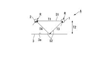
- a transmission antenna 1 and a reception antenna 2 that receives radio waves transmitted from the responding device are provided adjacent to each other, and the transmission antenna 1 transmits radio waves (main radio waves and transmission radio waves) to the responding device.
- a radio wave is received by the receiving antenna 2, and the transmission antenna 1 and the receiving antenna 2 are configured to simultaneously transmit and receive the radio wave.
- the antenna device A of the present embodiment includes a reflection member 3 that transmits radio waves from the transmission antenna 1 and reflects part of the leaked radio waves leaking from the transmission antenna 1 toward the reception antenna 2. Has been.
- the transmission antenna 1 and the reception antenna 2 are, for example, helical antennas, and the transmission antenna 1 and the reception antenna 2 have their axes O1 and O2 oriented in the same direction and at a predetermined interval T1.
- Side by side. That is, the transmission antenna 1 of the present embodiment is an antenna having directivity for transmitting radio waves toward a predetermined range and generating leaked radio waves outside the predetermined range. Further, it is an antenna that is formed in a rod shape and is generated by transmitting radio waves within a predetermined range from the end in the direction of the axis O1 and radiating leaked radio waves at the center of the axis O1.
- the reflecting member 3 is, for example, a reflecting mirror, a metal plate, a metal sheet, or the like.
- the reflecting member 3 is disposed with a predetermined interval T2 between the transmitting antenna 1 and the receiving antenna 2 with the reflecting surface 3a facing the transmitting antenna 1 and the receiving antenna 2 side. Further, at this time, the reflecting member 3 reflects the phase of the reflected wave S2 reflected from the reflecting member 3 and reaching the receiving antenna 2 with respect to the direct wave S1 radiated from the transmitting antenna 1 and reaching the receiving antenna 2 directly. It is disposed so as to reach the receiving antenna 2 with a shift.
- the reflecting member 3 is arranged so that the reflected wave S2 reaching the receiving antenna 2 is shifted by a half wavelength at the position of the receiving antenna with respect to the direct wave S1.
- the reflecting member 3 is not limited to being formed in a plate shape, and may be configured with, for example, a mesh structure or a grid structure as long as it can reflect radio waves.
- the antenna device A of the present embodiment configured as described above is used as a response device such as an RF tag for transmitting and receiving information, in which the transmitting antenna 1 and the receiving antenna 2 have directivity in the directions of the axes O1 and O2, respectively.
- Radio waves are transmitted from the transmission antenna 1.
- the transmitting antenna 1 generates leaked radio waves in the radiation direction centered on the axis O1.
- a leaked radio wave (direct wave S1, interference wave) radiated from the transmission antenna 1 is received by the reception antenna 2 adjacent to the transmission antenna 1 with a predetermined interval T1.
- the interference pattern becomes a large level and distortion occurs in the antenna pattern, so that the reception characteristic of the reception antenna 2 is deteriorated and the necessary gain and phase characteristic (isolation) cannot be secured.
- the antenna device A of the present embodiment includes the reflecting member 3, a part of the leaked radio wave radiated from the transmitting antenna 1 is reflected by the reflecting member 3 and reflected by the reflecting member 3.
- the reflected wave S2 reaches the receiving antenna 2.
- the reflecting member 3 has a half-wavelength at the position of the receiving antenna with respect to the direct wave S1 so that the reflected wave S2 reaches the receiving antenna 2 with a phase shifted from the direct wave S1. It arrange
- the difference (path difference) between the path T1 of the direct wave S1 directly reaching the receiving antenna 2 from the transmitting antenna 1 and the path (T3 + T4) of the reflected wave S2 reaching the receiving antenna 2 from the reflecting member 3 and the reflecting member 3 from the transmitting antenna 1. ) Is set so that the phases of the direct wave S1 and the reflected wave S2 reaching the receiving antenna 2 are shifted by a half wavelength.
- the direct wave S1 and the reflected wave S2 interfere with each other due to the phase difference between the direct wave S1 and the reflected wave S2 reaching the receiving antenna 2 (the direct wave S1 and the reflected wave S2 cancel each other), and the direct wave S1 is It is attenuated by the reflected wave S2.
- the interference wave is attenuated without providing a radio wave shield between the transmitting antenna 1 and the receiving antenna 2 as in the conventional antenna device.
- the interference wave is attenuated.
- the transmission antenna 1 and / or the reception antenna 2 is selected according to the distance T1 between the transmission antenna 1 and the reception antenna 2 and / or the frequency of the radio wave radiated from the transmission antenna 1. Isolation is ensured only by setting the relative position of the reflective member 3 to the direct wave S1 so that the reflected wave S2 interferes with the direct wave S1 and cancels each other.
- the reflecting member 3 and the transmitting antenna 1 and / or the receiving antenna 2 can be relatively moved in advance according to the distance T1 between the transmitting antenna 1 and the receiving antenna 2 and / or the frequency of the radio wave transmitted from the transmitting antenna 1. If the antenna device A is configured as described above, the path T1 of the direct wave S1 and the path (T3 + T4) of the reflected wave S2 even when the frequency of the radio wave and the distance T1 between the transmission antenna 1 and the reception antenna 2 are different.
- the relative positions of the transmitting antenna 1, the receiving antenna 2 and the reflecting member 3 can be easily and reliably set so that the difference is shifted by half a wavelength between the direct wave S1 and the reflected wave S2.
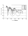
- FIG. 3 is a diagram showing the results of the demonstration experiment.
- the horizontal axis is the interval T2 between the transmitting antenna 1 and the receiving antenna 2
- the vertical axis is the isolation characteristic.
- the distance T1 between the two antennas 1 and 2 and the distance T2 between the transmitting antenna 1, the receiving antenna 2, and the reflecting member 3 are in a positional relationship in which interference between the direct wave S1 and the reflected wave S2 occurs. It was confirmed that a gain of about 8 to several tens dB can be gained. That is, the distance T1 between the antennas 1 and 2 and the distance T2 between the transmitting antenna 1 and the receiving antenna 2 and the reflecting member 3 are different from each other in the difference between the path T1 of the direct wave S1 and the path (T3 + T4) of the reflected wave S2. It has been proved that isolation can be ensured when the positional relationship of shifting the phase of the direct wave S1 and the reflected wave S2 reached (shifting the wavelength by half wavelength) is achieved.
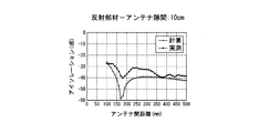
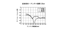
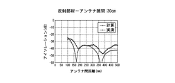
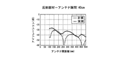
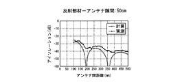
- FIGS. 4 to 9 the interval T2 between the transmitting antenna 1 and the receiving antenna 2 and the reflecting member 3 is changed stepwise to 6 cm, 10 cm, 20 cm, 30 cm, 40 cm, and 50 cm, and the transmitting antenna 1 in each case.
- the result of having confirmed the isolation characteristic by changing the distance T1 of the receiving antenna 2 is shown.
- FIGS. 4 to 9 show calculated values together with actual measured values.
- the calculation method of the calculated value will be described with reference to FIG. 2 showing the positional relationship between the transmitting antenna 1 and the receiving antenna 2 and the reflecting member 3.
- the propagation distance of the direct wave S1 is X
- the distance between the antennas is T1
- the radius of the transmission antenna 1 and the reception antenna 2 is R
- the propagation distance of the reflected wave S2 Z and the distance between the transmitting antenna 1 and the receiving antenna 2 and the reflecting member 3 is T2
- the amplitude value A 1 + cos (C Z ).
- the propagation loss of the direct wave S1 is V
- the antenna device A of the present embodiment a part of the leaked radio wave is reflected by the reflecting member so as to reach the reception antenna 2 with a phase shifted from the direct wave S1 of the leaky radio wave that reaches the reception antenna 2 directly from the transmission antenna 1.
- the direct wave S1 and the reflected wave S2 can be made to interfere with each other.
- the reflection member 3 is disposed so that the phase of the reflected wave S2 is shifted from the direct wave S1 without providing a radio wave shield between the transmitting antenna 1 and the receiving antenna 2 as in the conventional antenna device.
- the transmission antenna 1 and the reception antenna 2 In accordance with the distance T1 and / or the frequency of the radio wave transmitted from the transmission antenna 1, the relative position of the reflection member 3 with respect to the transmission antenna 1 and / or the reception antenna 2 is set so that the phases of the direct wave S1 and the reflected wave S2 are shifted. This makes it possible to ensure isolation easily and reliably.
- the transmission antenna 1 when the transmission antenna 1 has directivity for transmitting radio waves toward a predetermined range and leaks radio waves outside the predetermined range, the transmission antenna 1 When 1 is an antenna such as a helical antenna that is formed in a rod shape, transmits radio waves in a predetermined range from the end of the axis O1 direction, and leaks radio waves at the center of the axis O1, the reflection member 3 is provided. The direct wave S1 and the reflected wave S2 of the leaked radio wave are caused to interfere with each other so that the interference wave can be surely attenuated.
- the reflecting member 3 is disposed so that the reflected wave S2 of the leaked radio wave is shifted by a half wavelength at the receiving antenna position with respect to the direct wave S1, the direct wave S1 and the reflected wave S2 are caused to interfere with each other so as to cancel each other. It is possible to eliminate an interference wave that reaches the reception antenna 2 from the transmission antenna 1 and degrades the reception characteristics of the reception antenna 2.
- the reflecting member 3 and the transmitting antenna 1 and / or the receiving antenna 2 are configured to move relative to each other, the frequency of the radio wave transmitted from the transmitting antenna 1 and the distance T1 between the transmitting antenna 1 and the receiving antenna 2 are different. Even so, depending on the distance T1 between the transmitting antenna 1 and the receiving antenna 2 and / or the frequency of the radio wave transmitted from the transmitting antenna 1, the relative position of the reflecting member 3 with respect to the transmitting antenna 1 and / or the receiving antenna 2 is It is possible to easily set the reflected wave S2 and the direct wave S1 to be out of phase.
- an antenna device A can be suitably employed in an automatic toll collection system such as ERP (Electronic Road Pricing) installed in a toll booth such as a highway.
- ERP Electronic Road Pricing
- the antenna device A of the present embodiment is provided on the roof portion of a police vehicle so that information can be exchanged with a responder mounted on another vehicle, and the contents of the license plate of the other vehicle are identified.
- the present invention can also be suitably employed for acquiring data while traveling.
- the roof portion of the vehicle may be used as the reflecting member 3.
- the present invention has been described assuming that the transmission antenna 1 and the reception antenna 2 are helical antennas, the transmission antenna and the reception antenna according to the present invention are not necessarily limited to helical antennas.
- the path T1 of the direct wave S1 that directly reaches the receiving antenna 2 from the transmitting antenna 1 and the path (T3 + T4) of the reflected wave S2 that reaches the receiving antenna 2 from the reflecting member 3 and the reflecting member 3 from the transmitting antenna 1.
- the difference is set so that the phases of the direct wave S1 and the reflected wave S2 are shifted by a half wavelength.
- the path difference is appropriately adjusted to shift the phases of the direct wave S1 and the reflected wave S2, so that the interference effect between the direct wave S1 and the reflected wave S2 can be sufficiently obtained.
- the path difference may be determined by the direct wave S1 and the reflected wave S2. If the setting is made so as to deviate by half a wavelength, the interference effect between the direct wave S1 and the reflected wave S2 may be reduced. Even in such a case, the direct wave S1 and the reflected wave S2 are adjusted by appropriately adjusting the path difference. It is possible to enhance the interference effect and effectively eliminate the interference wave that degrades the reception characteristics of the reception antenna 2.
- the antenna device of the present invention it is possible to obtain an interference wave attenuation effect that reaches the receiving antenna from the transmitting antenna and degrades the receiving characteristics of the receiving antenna.
Landscapes
- Details Of Aerials (AREA)
- Aerials With Secondary Devices (AREA)
- Radar Systems Or Details Thereof (AREA)
Priority Applications (1)
| Application Number | Priority Date | Filing Date | Title |
|---|---|---|---|
| SG2013022710A SG189121A1 (en) | 2010-09-29 | 2011-09-26 | Antenna device |
Applications Claiming Priority (2)
| Application Number | Priority Date | Filing Date | Title |
|---|---|---|---|
| JP2010218634A JP5619555B2 (ja) | 2010-09-29 | 2010-09-29 | アンテナ装置 |
| JP2010-218634 | 2010-09-29 |
Publications (1)
| Publication Number | Publication Date |
|---|---|
| WO2012043442A1 true WO2012043442A1 (ja) | 2012-04-05 |
Family
ID=45892888
Family Applications (1)
| Application Number | Title | Priority Date | Filing Date |
|---|---|---|---|
| PCT/JP2011/071824 Ceased WO2012043442A1 (ja) | 2010-09-29 | 2011-09-26 | アンテナ装置 |
Country Status (3)
| Country | Link |
|---|---|
| JP (1) | JP5619555B2 (enExample) |
| SG (1) | SG189121A1 (enExample) |
| WO (1) | WO2012043442A1 (enExample) |
Cited By (2)
| Publication number | Priority date | Publication date | Assignee | Title |
|---|---|---|---|---|
| EP2940907A4 (en) * | 2012-12-26 | 2016-01-06 | Huawei Tech Co Ltd | ANTENNA SYSTEM |
| CN107579351A (zh) * | 2016-07-05 | 2018-01-12 | 安普泰科电子韩国有限公司 | 天线组件 |
Citations (4)
| Publication number | Priority date | Publication date | Assignee | Title |
|---|---|---|---|---|
| JP2006352871A (ja) * | 2005-06-13 | 2006-12-28 | Samsung Electronics Co Ltd | 隔離素子を含む平板型mimoアレーアンテナ |
| JP2007124235A (ja) * | 2005-10-27 | 2007-05-17 | Denso Corp | 放射ノイズの回り込み抑制方法 |
| JP2009124259A (ja) * | 2007-11-12 | 2009-06-04 | Japan Radio Co Ltd | アンテナ装置 |
| JP2010041291A (ja) * | 2008-08-04 | 2010-02-18 | Kddi Corp | 無線通信装置 |
-
2010
- 2010-09-29 JP JP2010218634A patent/JP5619555B2/ja active Active
-
2011
- 2011-09-26 SG SG2013022710A patent/SG189121A1/en unknown
- 2011-09-26 WO PCT/JP2011/071824 patent/WO2012043442A1/ja not_active Ceased
Patent Citations (4)
| Publication number | Priority date | Publication date | Assignee | Title |
|---|---|---|---|---|
| JP2006352871A (ja) * | 2005-06-13 | 2006-12-28 | Samsung Electronics Co Ltd | 隔離素子を含む平板型mimoアレーアンテナ |
| JP2007124235A (ja) * | 2005-10-27 | 2007-05-17 | Denso Corp | 放射ノイズの回り込み抑制方法 |
| JP2009124259A (ja) * | 2007-11-12 | 2009-06-04 | Japan Radio Co Ltd | アンテナ装置 |
| JP2010041291A (ja) * | 2008-08-04 | 2010-02-18 | Kddi Corp | 無線通信装置 |
Cited By (5)
| Publication number | Priority date | Publication date | Assignee | Title |
|---|---|---|---|---|
| EP2940907A4 (en) * | 2012-12-26 | 2016-01-06 | Huawei Tech Co Ltd | ANTENNA SYSTEM |
| US9941585B2 (en) | 2012-12-26 | 2018-04-10 | Huawei Technologies Co., Ltd. | Antenna system |
| CN107579351A (zh) * | 2016-07-05 | 2018-01-12 | 安普泰科电子韩国有限公司 | 天线组件 |
| TWI763682B (zh) * | 2016-07-05 | 2022-05-11 | 韓商太谷電子恩普(韓國)股份有限公司 | 天線組件 |
| CN107579351B (zh) * | 2016-07-05 | 2023-04-18 | 安普泰科电子韩国有限公司 | 天线组件 |
Also Published As
| Publication number | Publication date |
|---|---|
| JP5619555B2 (ja) | 2014-11-05 |
| JP2012073853A (ja) | 2012-04-12 |
| SG189121A1 (en) | 2013-05-31 |
Similar Documents
| Publication | Publication Date | Title |
|---|---|---|
| EP2522051B1 (en) | Antenna beam control elements, systems, architectures, and methods for radar, communications, and other applications | |
| KR100441146B1 (ko) | 이동통신 서비스용 중계기의 노치형 안테나 | |
| JP3523882B2 (ja) | アンテナ方位に基づくレーダ信号の選択 | |
| WO2017146163A1 (ja) | アンテナ装置 | |
| JP2011099685A (ja) | 車載レーダ装置、及びプログラム | |
| CA2751283A1 (en) | Radio frequency positioning system for vehicles | |
| KR20190058072A (ko) | 차량용 레이더 장치 | |
| JP2005249659A (ja) | レーダ装置用送受信アンテナ | |
| JP5619555B2 (ja) | アンテナ装置 | |
| JP6173242B2 (ja) | 探知妨害装置 | |
| JP2007057483A (ja) | ミリ波レーダ装置 | |
| JP2005244362A (ja) | ミリ波通信システム、ミリ波送信装置およびミリ波受信装置 | |
| JP3884772B2 (ja) | 偏平状のアンテナを自動車のウィンドウの内側に取り付けるためのアンテナ装置 | |
| JP2008535442A5 (enExample) | ||
| JP2009141983A (ja) | 全方向性を有する誘電体レンズを用いたアンテナ装置。 | |
| JP2018121127A (ja) | 無線装置 | |
| JP4246051B2 (ja) | レーダ装置 | |
| JPH06294834A (ja) | 自動車アンテナの感度測定方法 | |
| JP7255678B2 (ja) | アンテナ装置及びその設計方法 | |
| JPH10108251A (ja) | 路車間通信システムにおける電波遮蔽回避方式 | |
| JP5249959B2 (ja) | マルチパス低減装置 | |
| KR102848146B1 (ko) | 레이돔 안테나 | |
| JP7391734B2 (ja) | レーダシステムの試験設備 | |
| US9543659B2 (en) | Reflector antenna device | |
| US7365702B2 (en) | Antenna device |
Legal Events
| Date | Code | Title | Description |
|---|---|---|---|
| 121 | Ep: the epo has been informed by wipo that ep was designated in this application |
Ref document number: 11828996 Country of ref document: EP Kind code of ref document: A1 |
|
| NENP | Non-entry into the national phase |
Ref country code: DE |
|
| 122 | Ep: pct application non-entry in european phase |
Ref document number: 11828996 Country of ref document: EP Kind code of ref document: A1 |