WO2012042575A1 - 立体映像視聴用眼鏡 - Google Patents
立体映像視聴用眼鏡 Download PDFInfo
- Publication number
- WO2012042575A1 WO2012042575A1 PCT/JP2010/005896 JP2010005896W WO2012042575A1 WO 2012042575 A1 WO2012042575 A1 WO 2012042575A1 JP 2010005896 W JP2010005896 W JP 2010005896W WO 2012042575 A1 WO2012042575 A1 WO 2012042575A1
- Authority
- WO
- WIPO (PCT)
- Prior art keywords
- signal
- unit
- command
- period
- reception interval
- Prior art date
- Legal status (The legal status is an assumption and is not a legal conclusion. Google has not performed a legal analysis and makes no representation as to the accuracy of the status listed.)
- Ceased
Links
Images



Classifications
-
- H—ELECTRICITY
- H04—ELECTRIC COMMUNICATION TECHNIQUE
- H04N—PICTORIAL COMMUNICATION, e.g. TELEVISION
- H04N13/00—Stereoscopic video systems; Multi-view video systems; Details thereof
- H04N13/30—Image reproducers
- H04N13/332—Displays for viewing with the aid of special glasses or head-mounted displays [HMD]
- H04N13/341—Displays for viewing with the aid of special glasses or head-mounted displays [HMD] using temporal multiplexing
-
- G—PHYSICS
- G02—OPTICS
- G02B—OPTICAL ELEMENTS, SYSTEMS OR APPARATUS
- G02B30/00—Optical systems or apparatus for producing three-dimensional [3D] effects, e.g. stereoscopic images
- G02B30/20—Optical systems or apparatus for producing three-dimensional [3D] effects, e.g. stereoscopic images by providing first and second parallax images to an observer's left and right eyes
- G02B30/22—Optical systems or apparatus for producing three-dimensional [3D] effects, e.g. stereoscopic images by providing first and second parallax images to an observer's left and right eyes of the stereoscopic type
- G02B30/24—Optical systems or apparatus for producing three-dimensional [3D] effects, e.g. stereoscopic images by providing first and second parallax images to an observer's left and right eyes of the stereoscopic type involving temporal multiplexing, e.g. using sequentially activated left and right shutters
-
- H—ELECTRICITY
- H04—ELECTRIC COMMUNICATION TECHNIQUE
- H04N—PICTORIAL COMMUNICATION, e.g. TELEVISION
- H04N13/00—Stereoscopic video systems; Multi-view video systems; Details thereof
- H04N13/30—Image reproducers
- H04N13/398—Synchronisation thereof; Control thereof
-
- H—ELECTRICITY
- H04—ELECTRIC COMMUNICATION TECHNIQUE
- H04N—PICTORIAL COMMUNICATION, e.g. TELEVISION
- H04N2213/00—Details of stereoscopic systems
- H04N2213/008—Aspects relating to glasses for viewing stereoscopic images
Definitions
- the present invention relates to stereoscopic video viewing glasses for receiving a synchronization signal transmitted from a stereoscopic video display device that displays a stereoscopic video and allowing a viewer to view the stereoscopic video and a control method thereof.
- a display device that alternately displays images from the viewpoints of the left and right eyes constituting a stereoscopic image, and a viewer in synchronization with the display of the images from the left and right viewpoints of the display device.
- a stereoscopic video system that allows a viewer to view a stereoscopic video by using video viewing glasses that open and close a shutter provided in front of the left and right eyes (for example, Patent Document 1).
- the stereoscopic image viewing glasses When transmitting a synchronization signal from the stereoscopic image display device to the stereoscopic image viewing glasses, if transmission is performed by wireless communication using wireless or infrared rays, the stereoscopic image viewing glasses have noise other than the synchronization signal, for example, background noise ( It signals such as background noise) and other equipment emitted, also receives. The control of the stereoscopic video viewing glasses may be disturbed by these noises.
- background noise It signals such as background noise
- the invention of the present application aims to reduce the influence of these noises on the glasses for viewing stereoscopic images.
- the stereoscopic video viewing glasses calculate a period of a signal received from the outside, determine a valid signal according to the calculated period, and the effective reception from the signal received from the outside
- An effective command extraction unit that extracts only a simple signal, a filter control unit that controls a left eye filter unit and a right eye filter unit that adjust the amount of light incident on the left and right eyes of the viewer according to the extracted command, Is provided.
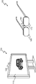
- FIG. 1 is a configuration diagram of a stereoscopic video system including a stereoscopic video display device and stereoscopic video viewing glasses described in the present embodiment.
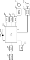
- FIG. It is a hardware block diagram of the glasses for stereoscopic video viewing described in the present embodiment.
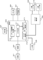
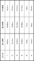
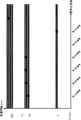
- FIG. 3 is a functional configuration diagram of stereoscopic video viewing glasses described in the present embodiment. It is a figure which shows the receiving timing of each signal which the spectacles for stereoscopic video viewing and reception and each receiving interval. It is a figure which shows the minimum reception interval, the maximum reception interval, and an average period of the received signal demonstrated in this Embodiment. Is a diagram showing the grouping of the reception signal described in this embodiment.
- FIG. 1 is a diagram showing a video display system including a video display device 100 that displays a stereoscopic video, and video viewing glasses 150 that a viewer wears when viewing the stereoscopic video displayed by the video display device 100. It is.
- the display unit 110 is a part that displays a video that the video display device 100 displays to the viewer.
- the left-eye image and the right-eye image are displayed alternately on the time axis or by switching at regular intervals.
- the synchronization signal transmission unit 120 transmits a synchronization signal synchronized with the stereoscopic video displayed on the display unit 110 to the outside, particularly to the video viewing glasses 150.
- a synchronization signal synchronized with the stereoscopic video displayed on the display unit 110 to the outside, particularly to the video viewing glasses 150.
- the video viewing glasses 150 include a right eye optical filter unit 160, a left eye optical filter unit 170, and a synchronization signal receiving unit 180.
- the right eye optical filter unit 160 controls the light incident on the right eye of the viewer wearing the video viewing glasses 150. More specifically, the amount of light incident on the right eye by the image displayed on the display unit 110 of the image display device 100 or the characteristics of the light is adjusted or changed.
- the left eye optical filter unit 170 controls the light incident on the left eye in the same manner as the right eye optical filter unit 160.
- the synchronization signal receiving unit 180 receives the synchronization signal transmitted from the synchronization signal transmitting unit 120 of the video display device 100.
- the video display system links the above configuration to allow viewers to view stereoscopic video.
- a stereoscopic video is displayed at a speed of 120 Hz, for example, a left-eye video and a right-eye video are alternately displayed or switched at regular intervals.
- the synchronization signal transmission unit 120 transmits a synchronization signal synchronized with the switching between the left-eye video and the right-eye video displayed on the display unit 110.
- the video viewing glasses 150 receive the synchronization signal output from the synchronization signal transmission unit 120 of the video display device 100 by the synchronization signal reception unit 180.
- the video viewing glasses 150 control the left eye optical filter unit 170 and the right eye optical filter unit 160 based on the received synchronization signal, so that the left viewer of the viewer wearing the video viewing glasses 150 eye, the light quantity incident on the right eye, or to control the optical characteristics. For example, when a synchronization signal indicating that a left-eye image is displayed on the display unit 110 of the image display device is received, the left-eye optical filter unit 170 is controlled to increase the amount of light incident on the left eye.
- the right-eye optical filter unit 160 reduces the amount of light incident on the right eye.
- the viewer views the left-eye video displayed on the display unit 110 with the left eye and does not view with the right eye.
- the left-eye optical filter unit 170 reduces the amount of light incident on the left eye, and the right-eye optics.
- filter unit 160 increases the amount of light entering the right eye.
- the video for the right eye displayed on the display unit 110 is viewed with the viewer's right eye and not viewed with the left eye.
- the viewer displays the video displayed on the display unit 110. Perceived to have parallax. As a result, even if the display unit 110 is a display device having a substantially planar shape, the viewer can feel that the video displayed there is three-dimensional.
- FIG. 2 is a diagram illustrating a hardware configuration of the video viewing glasses 150.
- the eyeglasses for viewing video 150 have, as hardware configurations, an infrared light receiving sensor (IR sensor) 201, an amplifier 202, an LED 203, a CPU 204, a switch (SW) 205, a ROM 206, a RAM 207, and a clock (CLK) 208.
- IR sensor infrared light receiving sensor
- SW switch
- ROM 206 read-only memory
- RAM 207 a read-only memory
- CLK clock
- the IR sensor 201 is a sensor that receives a synchronization signal transmitted from the stereoscopic video display device 100.
- the IR sensor 201 converts the received infrared light into an electrical signal.
- the synchronization signal is described as being propagated by infrared rays, but the present invention is not limited to this. Other methods may be used as long as the synchronization signal is propagated by a wireless method such as radio.
- the amplifier 202 appropriately amplifies the electric signal so that the electric signal output from the IR sensor 201 can be easily processed by a subsequent processing block.
- the LED 203 is lit to clearly indicate the operation contents to the user when the stereoscopic video viewing glasses 150 are operating or when the switch 205 is input and the power is turned on.
- the CPU 204 controls the whole of the stereoscopic video viewing glasses 150.
- a CPU is described as an example, but a similar process may be performed by a DSP, FPGA, or the like.
- the switch (SW) 205 is an interface for realizing input to the stereoscopic video viewing glasses 150 from the outside.
- the ROM 206 holds programs for operating the CPU 204 and the like, operation parameters, initial values, and the like.
- the ROM 206 may use a rewritable flash memory or the like.
- the RAM 207 holds variable values and the like temporarily held by the CPU 204 program during operation.
- the clock (CLK) 208 oscillates a reference clock for operating the CPU 204 and other hardware components.
- the analog switches 209 and 211 perform a driving process for driving an opening / closing operation of shutters 210 and 212 described later.
- the two analog switches 209 and 211 are provided because they are necessary to drive the left and right eye shutters 210 and 212, respectively.
- the shutters 210 and 212 are provided in front of the left and right eyes of the viewer, and are opened and closed in synchronization with the video displayed by the stereoscopic video display device 100.
- FIG. 3 is a diagram illustrating a functional configuration of the stereoscopic video viewing glasses 150.
- the stereoscopic video viewing glasses 150 have a functional configuration such as a reception unit 301, an amplification unit 302, a display unit 303, a calculation unit 304, an input unit 305, a memory unit 306, a reference signal generation unit 307, and a drive.
- the receiving unit 301 receives a synchronization signal transmitted from the stereoscopic video display device 100.
- the receiving unit 301 corresponds to the IR sensor 201 in FIG.
- the amplifying unit 302 amplifies the signal received by the receiving unit 301.
- the amplification unit 302 corresponds to the amplifier 202 in FIG.
- the display unit 303 displays various information to the user by the stereoscopic video viewing glasses 150.
- the display unit 303 corresponds to the LED 203 in FIG. 2, but the display method is not limited to the LED. Any realization method may be used as long as information is displayed to the user by other methods.
- the calculation unit 304 performs overall control of the stereoscopic video viewing glasses 150.
- the calculation unit 304 corresponds to the CPU 204 in FIG.
- the input unit 305 receives various instructions from the user.
- the input unit 305 corresponds to the switch 205 in FIG.
- the memory unit 306 holds various types of information permanently or temporarily.
- the memory unit 306 corresponds to the ROM 206 and the RAM 207 in FIG.
- the reference signal generation unit 307 generates a reference signal necessary for the operation of the arithmetic unit 304 or the like.
- the reference signal generation unit 307 corresponds to the clock 208 in FIG.
- the driving unit 308 generates and outputs a signal for operating a shutter of the left eye filter unit 309 and the right eye filter unit 310 described later.
- the filter driving unit 308 corresponds to the analog switches 209 and 211 in FIG.
- the left eye filter unit 309 and the right eye filter unit 310 control the amount of light incident on the left and right eyes of the viewer.
- the left eye filter unit 309 and the right eye filter unit 310 correspond to the shutters 210 and 212 in FIG.
- the calculation unit 304 further includes an input switching unit 311, a command reception interval calculation unit 312, a valid command extraction unit 313, and a filter control unit 314.
- the input switching unit 311 controls whether the arithmetic unit 304 accepts the synchronization signal input from the receiving unit 301 and the amplifying unit 302.
- the input switching unit 311 corresponds to, for example, validity / invalidity of the input port in the CPU 204 in FIG.
- the command reception interval calculation unit 312 calculates reception periods of various signals received by the reception unit 301 and the like, and distinguishes between a valid command and other signals (noise) and the like by a reception command grouping process or the like. Will be described later distinguish how the effective command and other signals.
- the valid command extraction unit 313 calculates reception periods of various signals by the command reception interval calculation unit 312 and extracts commands that are distinguished as valid from the actual received commands. Only the command extracted from the received signal by the valid command extraction unit 313 is output to the filter control unit described later.
- the filter control unit 314 controls opening and closing of the left eye filter unit 309 and the right eye filter unit 310 via the drive unit 308 in accordance with the command extracted by the valid command extraction unit 313.
- FIG. 4 is a diagram illustrating reception timings of received signals and respective periods.
- FIG. 4A shows a signal received by the stereoscopic video viewing glasses 150 on the time axis.
- FIG. 4B is a diagram in which the period of each type of command received by the stereoscopic video viewing glasses 150 is calculated.
- the stereoscopic video viewing glasses 150 receive other signals (noise) and other signals in addition to commands for controlling the opening and closing of the left eye filter unit 309 and the right eye filter unit 310.
- FIG. 4A and FIG. 4B there are six types of signals including these noises.
- it is assumed that six types of commands from the first to the sixth in FIG. 4A are defined as commands for controlling the stereoscopic video viewing glasses 150, and are effective from those command strings. A method for extracting commands will be described.
- the command reception interval calculation unit 312 calculates the period of each signal based on the reception timing of these signals. . For example, for the first signal, the command reception interval calculation unit 312 measures the time from when the first signal is first received until the next first signal is received. This measurement is based on the reference signal supplied from the reference signal generation unit 307. The command reception interval calculation unit 312 acquires the reception interval T11 by this measurement. The command reception interval calculation unit 312 obtains reception intervals T12 and T13 in the case of FIG. 4 by repeating the same measurement every time the first signal is received for the first command.
- the command reception interval calculation unit 312 similarly measures the reception intervals of the respective signal receptions for the second to sixth signal receptions as well. For the second signal, receive intervals T21, T22, T23, for the third signal, receive intervals T31, T32, T33, for the fourth signal, receive intervals T41, T42, T43, The command reception interval calculation unit 312 acquires reception intervals T51, T52, and T53 for signals, and reception intervals T61 and T62 for the sixth signal.
- the command reception interval calculation unit 312 calculates each period for each signal type from the acquired reception interval. For the first signal, the command reception interval calculation unit 312 determines the period T1 of the first signal from the acquired reception interval by the following calculation formula.
- T1 (T11 + T12 + T13) / 3
- the command reception interval calculation unit 312 also performs the second signal cycle T2, the third signal cycle T3, the fourth signal cycle T4, the fifth signal cycle T5, and the sixth signal cycle T6. Similarly, each period is calculated.
- T2 (T21 + T22 + T23) / 3
- T3 (T31 + T32 + T33) / 3
- T4 (T41 + T42 + T43) / 3
- T5 (T51 + T52 + T53) / 3
- T6 (T61 + T62) / 2
- FIG. 5 shows an example in which the period of the first to sixth signals is calculated.
- FIG. 5 shows the time interval when the reception interval is minimum for each command, the time interval when the reception interval is maximum, and the period (average period) of each signal calculated by the above formula and the like. It shows.
- the period of the first to sixth signals is a value obtained by averaging the reception intervals acquired for each signal, but the invention of the present application is not limited to this.
- an intermediate value may be adopted from a plurality of acquired reception interval values, and another method is to use an average value obtained by removing the minimum value and the maximum value. There may be. In other words, any calculation method may be used as long as the representative reception interval is calculated based on the reception interval of the actually received signal.
- the command reception interval calculation unit 312 does not necessarily need to fix the period for each signal to a period once determined.
- the period may be updated every time a command is received. In this case, when the display cycle is changed for each scene on the stereoscopic video display device side, the stereoscopic video viewing glasses 150 can follow the change of the command cycle.
- the command reception interval calculation unit 312 performs grouping processing based on the cycle calculated for each received signal. There are several grouping methods.
- the command reception interval calculation unit 312 may have a period in which the left and right eye filters are opened and closed in advance coincide with one of several predetermined periods. In such a case, the command reception interval calculation unit 312 performs grouping of received signals from the predetermined period.
- the signal that should be received by the command reception interval calculation unit 312 is a command for opening the left eye filter unit 309, a command for closing the left eye filter unit 309, a command for opening the right eye filter unit 310, a command for closing the right eye filter unit 310, In this case, the operation according to these commands is as shown in FIG. Based on these periods, the command reception interval calculation unit 312 can estimate that each signal (command) is received at a reception interval that is approximately twice the frame display time.
- the command reception interval calculation unit 312 estimates a signal received at a reception interval in the vicinity of 16.6 (ms), which is twice 8.3 (ms), as an effective command.
- the other signals an invalid signal (noise).
- the command reception interval calculation unit 312 groups the first to fourth signals as valid commands, and determines the fifth and sixth signals as noise. That is, the command reception interval calculation unit 312 can determine whether or not the command is a valid command based on whether or not the period of the received signal is in the vicinity of an integral multiple of a predetermined period.
- “near” is a case where there is an error range and signal period of several percent before and after the theoretical command period.
- the command reception interval calculation unit 312 can group effective commands based only on the calculated period of each signal.
- the command reception interval calculation unit 312 has other values within the range of 97% to 103% (that is, a range of 3% before and after the value) of the period of each signal from the period of each signal shown in FIG. performing grouping on whether include periodic signals.
- the first to fourth signals are all within the range of 3% before and after this, but the fifth and sixth signals are not included. Absent.
- the command reception interval calculation unit 312 can group only valid commands.
- the width of 3% is used as an example, but the present invention is not limited to this value.
- FIG. 7 illustrates a result of grouping by the command reception interval calculation unit 312.
- FIG. 7 describes the signals received at each vertex of the polygon, and the signals determined to be effective groups by the command reception interval calculation unit 312 are mutually connected in practice. In this way, and only the valid signal can be clearly understood.
- the valid command extraction unit 313 extracts only signals recognized as valid commands by the command reception interval calculation unit 312 from the signals input from the reception unit 301 and the amplification unit 302. The valid command extraction unit 313 ignores other input signals.
- the valid command extraction unit 313 controls the opening / closing operation of the left eye filter unit 309 and the right eye filter unit 310 via the filter control unit 314 and the filter driving unit 308 according to the control content of the valid command (FIG. 4C). ).
- the stereoscopic video viewing glasses 150 reduce control disturbance due to noise.
- FIG. 8 shows another example of the embodiment of the present invention, and is a diagram showing reception timing of received signals and respective periods.
- FIG. 8A shows a signal received by the stereoscopic video viewing glasses 150 on the time axis.
- FIG. 8B is a diagram in which the period of each type of command received by the stereoscopic video viewing glasses 150 is calculated.
- the first signal (the number “1” surrounded by a circle in FIG. 8A). And subscript numbers “1” to “5”) indicate that noise is mixed and the command is received irregularly.
- FIG. 8A shows a signal received by the stereoscopic video viewing glasses 150 on the time axis.
- FIG. 8B is a diagram in which the period of each type of command received by the stereoscopic video viewing glasses 150 is calculated.
- the first signal (the number “1” surrounded by a circle in FIG. 8A).
- FIG. 8A shows a
- the command sequence of the first signal is described using the symbols “1 1 ” to “1 5 ” corresponding to the numbers surrounded by the circles representing the first signal. .
- a method of extracting a valid command from the command sequence of the first signal (“1 1 ” to “1 5 ”) will be described.
- the command reception interval calculation unit 312 determines the reception interval of each signal based on the reception timing of these signals. calculate. In the example of FIG. 8, the command reception interval calculation unit 312 acquires a total of 10 reception intervals from the reception interval T 1-12 to T 1-45 .
- FIG. 9 shows the result, which means that the command intervals of T 1-12 , T 1-14 , and T 1-24 are received at an integer multiple of the presumed frame interval. From the five first signals examined, it can be estimated that the three signals “1 1 ”, “1 2 ”, and “1 4 ” are correct control signals.
- the command reception interval calculation unit 312 estimates a signal received at a reception interval near 16.6 (ms), which is twice 8.3 (ms), as an effective command. Other signals are invalid signals (noise). From the result of FIG. 9, the command reception interval calculation unit 312 groups “1 1 ”, “1 2 ”, and “1 4 ” as valid commands, and sets “1 3 ” and “1 5 ” as invalid signals (noise). ). That is, the command reception interval calculation unit 312 can determine whether or not the signal is valid based on whether or not the period of the received signal is near an integer multiple of a predetermined period.
- the stereoscopic video viewing glasses 150 reduce control disturbance due to noise.
- calculation unit 304 (the input switching unit 311, the command reception interval calculation unit 312, the valid command extraction unit 313, and the filter control unit 314) described in this embodiment is realized as a software program of the CPU 204 shown in FIG. It can also be realized as a hardware configuration such as an FPGA.
- the embodiment described above mainly includes the following configuration.
- the glasses for stereoscopic video viewing calculate a period of a signal received from the outside, and determine a valid signal according to the calculated period, and a signal received from the outside
- An effective command extraction unit that extracts only the effective signal
- a filter control unit that controls a left eye filter unit and a right eye filter unit that adjust the amount of light incident on the left and right eyes of the viewer according to the extracted command And.
- the stereoscopic video viewing glasses to accept commands during a period in which a command is received from the outside, so the probability of receiving noise is low and the possibility of disturbing the control of the stereoscopic video viewing glasses is reduced. be able to.
- the command reception interval calculation unit calculates the period of the signal received from the outside for each signal type, and the difference between the integer multiple of the calculated period and a preset period is within a predetermined range. the composed signal, it is preferable to determine the valid signal.
- the stereoscopic video viewing glasses can reduce the possibility that the control is disturbed by noise.
- the command reception interval calculation unit calculates the period of a signal received from the outside for each type of signal, and determines an effective signal according to the magnitude of the period error between the signals. .
- the stereoscopic video viewing glasses can reduce the possibility that the control is disturbed by noise.
- the invention of the present application is used for stereoscopic video viewing glasses that perform opening / closing control of a shutter (filter) based on a signal from a stereoscopic video display device.
Landscapes
- Physics & Mathematics (AREA)
- Engineering & Computer Science (AREA)
- Multimedia (AREA)
- Signal Processing (AREA)
- General Physics & Mathematics (AREA)
- Optics & Photonics (AREA)
- Testing, Inspecting, Measuring Of Stereoscopic Televisions And Televisions (AREA)
Abstract
Description
図1は、立体映像を表示する映像表示装置100と、映像表示装置100が表示する立体映像を視聴する際に視聴者が装着する映像視聴用眼鏡150と、を備える映像表示システムを示した図である。
図2は、映像視聴用眼鏡150のハードウェア構成を示した図である。映像視聴用眼鏡150は、ハードウェア構成として、赤外線受光センサ(IRセンサ)201と、アンプ202と、LED203と、CPU204と、スイッチ(SW)205と、ROM206と、RAM207と、クロック(CLK)208と、アナログスイッチ209と、シャッター210と、アナログスイッチ211と、シャッター212とを有する。
図3は、立体映像視聴用眼鏡150の機能構成を示す図である。立体映像視聴用眼鏡150は、機能構成として、受信部301と、増幅部302と、表示部303と、演算部304と、入力部305と、メモリ部306と、基準信号生成部307と、駆動部308と、左眼フィルタ部309と、右眼フィルタ部310と、を有する。
図4は、受信信号の受信タイミングとそれぞれの周期を示す図である。図4(a)は、立体映像視聴用眼鏡150が受信する信号を時間軸上で示した図である。図4(b)は、立体映像視聴用眼鏡150が受信したそれぞれの種類のコマンドの周期を算出した図である。立体映像視聴用眼鏡150は、左眼フィルタ部309、右眼フィルタ部310の開閉を制御するコマンド以外の、その他の信号(ノイズ)等の信号も含めて受信している。図4(a)、図4(b)にはこれらノイズを含めた6種類の信号が存在している。図4に示す例では、立体映像視聴用眼鏡150を制御するコマンドとして、図4(a)の第1から第6までの6種類のコマンドが定義されているとして、それらのコマンド列から有効なコマンドを抽出する方法を説明する。
T3 = (T31+T32+T33)/3
T4 = (T41+T42+T43)/3
T5 = (T51+T52+T53)/3
T6 = (T61+T62)/2
コマンド受信間隔算出部312は、受信した信号毎に算出した周期に基づいてグルーピング処理を行う。グルーピングの方法には幾つかの方法がある。
1000(ms) / 120(Hz) = 8.3(ms/frame)
となる。
有効コマンド抽出部313は、受信部301、増幅部302から入力される信号から、コマンド受信間隔算出部312により有効コマンドと認められた信号のみを抽出する。有効コマンド抽出部313は、それ以外に入力される信号については無視する。有効コマンド抽出部313は、有効コマンドの制御内容にしたがって、フィルタ制御部314、フィルタ駆動部308を介して左眼フィルタ部309、右眼フィルタ部310の開閉動作を制御する(図4(c))。
1000(ms) / 120(Hz) = 8.3(ms/frame)
となり、その2倍の約16.6msに、取得したコマンド受信間隔が一致するかどうかをコマンド受信間隔算出部312は判定する。
Claims (3)
- 外部から受信した信号の周期を算出し、算出した周期に従って有効な信号を決定するコマンド受信間隔算出部と、
外部から受信した信号から前記有効な信号のみを抽出する有効コマンド抽出部と、
前記抽出されたコマンドに従って、視聴者の左右両眼に入射する光量を調整する左眼フィルタ部と右眼フィルタ部とを制御するフィルタ制御部と、
を備える立体映像視聴用眼鏡。 - 前記コマンド受信間隔算出部は、外部から受信した信号の周期を信号の種類毎に算出し、該算出した周期の整数倍と予め設定された周期との差が所定の範囲内となる信号を、有効な信号と決定する、
請求項1に記載の立体映像視聴用眼鏡。 - 前記コマンド受信間隔算出部は、外部から受信した信号の周期を信号の種類毎に算出し、該信号相互間の周期の誤差の大きさにより、有効な信号を決定する、
請求項1に記載の立体映像視聴用眼鏡。
Priority Applications (4)
| Application Number | Priority Date | Filing Date | Title |
|---|---|---|---|
| CN2010900007010U CN202514019U (zh) | 2010-09-30 | 2010-09-30 | 立体影像收看用眼镜 |
| PCT/JP2010/005896 WO2012042575A1 (ja) | 2010-09-30 | 2010-09-30 | 立体映像視聴用眼鏡 |
| DE212010000155U DE212010000155U1 (de) | 2010-09-30 | 2010-09-30 | Brille zum Beobachten stereoskopischer Bilder |
| FR1158455A FR2965694B3 (fr) | 2010-09-30 | 2011-09-22 | Lunettes de vision d'images stereoscopiques |
Applications Claiming Priority (1)
| Application Number | Priority Date | Filing Date | Title |
|---|---|---|---|
| PCT/JP2010/005896 WO2012042575A1 (ja) | 2010-09-30 | 2010-09-30 | 立体映像視聴用眼鏡 |
Publications (1)
| Publication Number | Publication Date |
|---|---|
| WO2012042575A1 true WO2012042575A1 (ja) | 2012-04-05 |
Family
ID=45868967
Family Applications (1)
| Application Number | Title | Priority Date | Filing Date |
|---|---|---|---|
| PCT/JP2010/005896 Ceased WO2012042575A1 (ja) | 2010-09-30 | 2010-09-30 | 立体映像視聴用眼鏡 |
Country Status (4)
| Country | Link |
|---|---|
| CN (1) | CN202514019U (ja) |
| DE (1) | DE212010000155U1 (ja) |
| FR (1) | FR2965694B3 (ja) |
| WO (1) | WO2012042575A1 (ja) |
Citations (4)
| Publication number | Priority date | Publication date | Assignee | Title |
|---|---|---|---|---|
| JPS62239784A (ja) * | 1986-04-11 | 1987-10-20 | Sanyo Electric Co Ltd | 立体テレビジヨンコントロ−ルシステム |
| JPH0292187A (ja) * | 1988-09-29 | 1990-03-30 | Victor Co Of Japan Ltd | 立体画像用メガネ装置 |
| JPH1198538A (ja) * | 1997-09-19 | 1999-04-09 | Sanyo Electric Co Ltd | 液晶シャッタ眼鏡の駆動装置 |
| JP2010273259A (ja) * | 2009-05-25 | 2010-12-02 | Sony Corp | 受信装置、シャッタメガネ、および送受信システム |
Family Cites Families (1)
| Publication number | Priority date | Publication date | Assignee | Title |
|---|---|---|---|---|
| DE4238046A1 (de) | 1992-11-11 | 1994-05-19 | Basf Ag | Neue Bis-(4-substituierte-2,6-diisopropyl-phenyl)-carbodiimide, ein Verfahren zu ihrer Herstellung und ihre Verwendung sowie die zu ihrer Herstellung verwendbaren 4-substituierten 2,6-Diisopropyl-phenylisocyanate |
-
2010
- 2010-09-30 CN CN2010900007010U patent/CN202514019U/zh not_active Expired - Fee Related
- 2010-09-30 WO PCT/JP2010/005896 patent/WO2012042575A1/ja not_active Ceased
- 2010-09-30 DE DE212010000155U patent/DE212010000155U1/de not_active Expired - Lifetime
-
2011
- 2011-09-22 FR FR1158455A patent/FR2965694B3/fr not_active Expired - Lifetime
Patent Citations (4)
| Publication number | Priority date | Publication date | Assignee | Title |
|---|---|---|---|---|
| JPS62239784A (ja) * | 1986-04-11 | 1987-10-20 | Sanyo Electric Co Ltd | 立体テレビジヨンコントロ−ルシステム |
| JPH0292187A (ja) * | 1988-09-29 | 1990-03-30 | Victor Co Of Japan Ltd | 立体画像用メガネ装置 |
| JPH1198538A (ja) * | 1997-09-19 | 1999-04-09 | Sanyo Electric Co Ltd | 液晶シャッタ眼鏡の駆動装置 |
| JP2010273259A (ja) * | 2009-05-25 | 2010-12-02 | Sony Corp | 受信装置、シャッタメガネ、および送受信システム |
Also Published As
| Publication number | Publication date |
|---|---|
| FR2965694A3 (fr) | 2012-04-06 |
| DE212010000155U1 (de) | 2012-07-10 |
| CN202514019U (zh) | 2012-10-31 |
| FR2965694B3 (fr) | 2012-09-21 |
Similar Documents
| Publication | Publication Date | Title |
|---|---|---|
| KR101446559B1 (ko) | 3차원 영상 시청을 위한 신호생성방법 및 이를 적용한영상시청장치 | |
| JP2011193460A (ja) | 3d映像画質調整方法、3dディスプレイ装置、3dメガネ及び3d映像提供システム | |
| WO2010141514A3 (en) | Method of stereoscopic synchronization of active shutter glasses | |
| WO2012047073A3 (ko) | 3차원 안경, 3차원 영상 디스플레이 장치 및 3차원 안경/영상 디스플레이 장치 구동방법 | |
| JP2011139456A (ja) | 3dグラスの駆動方法及びこれを用いた3dグラスと3dディスプレイ装置 | |
| EP3091443A3 (en) | Viewer-centric user interface for stereoscopic cinema | |
| US20120099195A1 (en) | Eyewear, three-dimensional image display system employing the same, and method of allowing viewing of image | |
| JP2012142748A (ja) | 撮像制御装置、撮像制御方法及び撮像制御プログラム並びに撮像装置 | |
| JP2011142606A5 (ja) | ||
| KR20130065611A (ko) | 디스패리티 설정 방법 및 대응하는 디바이스 | |
| JP2013123220A5 (ja) | ||
| CN102740091A (zh) | 用于传统电视的三维控制器系统 | |
| JP3172275U (ja) | 立体映像視聴用眼鏡 | |
| WO2012042575A1 (ja) | 立体映像視聴用眼鏡 | |
| CN102811356B (zh) | 以3d显示器同时播送多个2d图像给多个使用者的方法 | |
| US8441413B2 (en) | Apparatus and system for viewing 3D image | |
| JP3173405U (ja) | 立体映像視聴用眼鏡 | |
| US20130002836A1 (en) | 3d display apparatus and 3d display method thereof | |
| CN104823445B (zh) | 立体观察装置与显示同步 | |
| JP2012019376A (ja) | 立体映像観賞用メガネ | |
| JP2012227678A (ja) | 表示装置及び映像システム | |
| WO2012035734A1 (ja) | 立体映像視聴用眼鏡及びその制御方法 | |
| KR101530022B1 (ko) | 3차원 영상 시청을 위한 신호생성방법 및 이를 적용한 영상시청장치 | |
| JP2013055560A5 (ja) | ||
| JP2011228797A (ja) | 表示装置 |
Legal Events
| Date | Code | Title | Description |
|---|---|---|---|
| WWE | Wipo information: entry into national phase |
Ref document number: 201090000701.0 Country of ref document: CN |
|
| WWE | Wipo information: entry into national phase |
Ref document number: 2011600041 Country of ref document: JP |
|
| WWE | Wipo information: entry into national phase |
Ref document number: 212010000155 Country of ref document: DE Ref document number: 2120100001551 Country of ref document: DE |
|
| 121 | Ep: the epo has been informed by wipo that ep was designated in this application |
Ref document number: 10857792 Country of ref document: EP Kind code of ref document: A1 |
|
| 122 | Ep: pct application non-entry in european phase |
Ref document number: 10857792 Country of ref document: EP Kind code of ref document: A1 |