WO2012039186A1 - 印字方法および印字装置 - Google Patents
印字方法および印字装置 Download PDFInfo
- Publication number
- WO2012039186A1 WO2012039186A1 PCT/JP2011/066000 JP2011066000W WO2012039186A1 WO 2012039186 A1 WO2012039186 A1 WO 2012039186A1 JP 2011066000 W JP2011066000 W JP 2011066000W WO 2012039186 A1 WO2012039186 A1 WO 2012039186A1
- Authority
- WO
- WIPO (PCT)
- Prior art keywords
- printing
- ink
- region
- capillary force
- aggregate
- Prior art date
Links
Images


Classifications
-
- B—PERFORMING OPERATIONS; TRANSPORTING
- B41—PRINTING; LINING MACHINES; TYPEWRITERS; STAMPS
- B41J—TYPEWRITERS; SELECTIVE PRINTING MECHANISMS, i.e. MECHANISMS PRINTING OTHERWISE THAN FROM A FORME; CORRECTION OF TYPOGRAPHICAL ERRORS
- B41J11/00—Devices or arrangements of selective printing mechanisms, e.g. ink-jet printers or thermal printers, for supporting or handling copy material in sheet or web form
- B41J11/0015—Devices or arrangements of selective printing mechanisms, e.g. ink-jet printers or thermal printers, for supporting or handling copy material in sheet or web form for treating before, during or after printing or for uniform coating or laminating the copy material before or after printing
-
- B—PERFORMING OPERATIONS; TRANSPORTING
- B41—PRINTING; LINING MACHINES; TYPEWRITERS; STAMPS
- B41J—TYPEWRITERS; SELECTIVE PRINTING MECHANISMS, i.e. MECHANISMS PRINTING OTHERWISE THAN FROM A FORME; CORRECTION OF TYPOGRAPHICAL ERRORS
- B41J3/00—Typewriters or selective printing or marking mechanisms characterised by the purpose for which they are constructed
- B41J3/407—Typewriters or selective printing or marking mechanisms characterised by the purpose for which they are constructed for marking on special material
- B41J3/4078—Printing on textile
-
- B—PERFORMING OPERATIONS; TRANSPORTING
- B41—PRINTING; LINING MACHINES; TYPEWRITERS; STAMPS
- B41J—TYPEWRITERS; SELECTIVE PRINTING MECHANISMS, i.e. MECHANISMS PRINTING OTHERWISE THAN FROM A FORME; CORRECTION OF TYPOGRAPHICAL ERRORS
- B41J11/00—Devices or arrangements of selective printing mechanisms, e.g. ink-jet printers or thermal printers, for supporting or handling copy material in sheet or web form
- B41J11/0015—Devices or arrangements of selective printing mechanisms, e.g. ink-jet printers or thermal printers, for supporting or handling copy material in sheet or web form for treating before, during or after printing or for uniform coating or laminating the copy material before or after printing
- B41J11/002—Curing or drying the ink on the copy materials, e.g. by heating or irradiating
-
- B—PERFORMING OPERATIONS; TRANSPORTING
- B41—PRINTING; LINING MACHINES; TYPEWRITERS; STAMPS
- B41J—TYPEWRITERS; SELECTIVE PRINTING MECHANISMS, i.e. MECHANISMS PRINTING OTHERWISE THAN FROM A FORME; CORRECTION OF TYPOGRAPHICAL ERRORS
- B41J2/00—Typewriters or selective printing mechanisms characterised by the printing or marking process for which they are designed
- B41J2/005—Typewriters or selective printing mechanisms characterised by the printing or marking process for which they are designed characterised by bringing liquid or particles selectively into contact with a printing material
- B41J2/01—Ink jet
- B41J2/21—Ink jet for multi-colour printing
- B41J2/2107—Ink jet for multi-colour printing characterised by the ink properties
- B41J2/2114—Ejecting transparent or white coloured liquids, e.g. processing liquids
-
- B—PERFORMING OPERATIONS; TRANSPORTING
- B41—PRINTING; LINING MACHINES; TYPEWRITERS; STAMPS
- B41M—PRINTING, DUPLICATING, MARKING, OR COPYING PROCESSES; COLOUR PRINTING
- B41M5/00—Duplicating or marking methods; Sheet materials for use therein
- B41M5/0011—Pre-treatment or treatment during printing of the recording material, e.g. heating, irradiating
- B41M5/0017—Application of ink-fixing material, e.g. mordant, precipitating agent, on the substrate prior to printing, e.g. by ink-jet printing, coating or spraying
-
- B—PERFORMING OPERATIONS; TRANSPORTING
- B41—PRINTING; LINING MACHINES; TYPEWRITERS; STAMPS
- B41M—PRINTING, DUPLICATING, MARKING, OR COPYING PROCESSES; COLOUR PRINTING
- B41M5/00—Duplicating or marking methods; Sheet materials for use therein
- B41M5/0041—Digital printing on surfaces other than ordinary paper
- B41M5/0047—Digital printing on surfaces other than ordinary paper by ink-jet printing
-
- B—PERFORMING OPERATIONS; TRANSPORTING
- B41—PRINTING; LINING MACHINES; TYPEWRITERS; STAMPS
- B41M—PRINTING, DUPLICATING, MARKING, OR COPYING PROCESSES; COLOUR PRINTING
- B41M5/00—Duplicating or marking methods; Sheet materials for use therein
- B41M5/0041—Digital printing on surfaces other than ordinary paper
- B41M5/0064—Digital printing on surfaces other than ordinary paper on plastics, horn, rubber, or other organic polymers
-
- B—PERFORMING OPERATIONS; TRANSPORTING
- B41—PRINTING; LINING MACHINES; TYPEWRITERS; STAMPS
- B41M—PRINTING, DUPLICATING, MARKING, OR COPYING PROCESSES; COLOUR PRINTING
- B41M7/00—After-treatment of prints, e.g. heating, irradiating, setting of the ink, protection of the printed stock
- B41M7/0081—After-treatment of prints, e.g. heating, irradiating, setting of the ink, protection of the printed stock using electromagnetic radiation or waves, e.g. ultraviolet radiation, electron beams
-
- B—PERFORMING OPERATIONS; TRANSPORTING
- B41—PRINTING; LINING MACHINES; TYPEWRITERS; STAMPS
- B41M—PRINTING, DUPLICATING, MARKING, OR COPYING PROCESSES; COLOUR PRINTING
- B41M7/00—After-treatment of prints, e.g. heating, irradiating, setting of the ink, protection of the printed stock
- B41M7/009—After-treatment of prints, e.g. heating, irradiating, setting of the ink, protection of the printed stock using thermal means, e.g. infrared radiation, heat
-
- C—CHEMISTRY; METALLURGY
- C09—DYES; PAINTS; POLISHES; NATURAL RESINS; ADHESIVES; COMPOSITIONS NOT OTHERWISE PROVIDED FOR; APPLICATIONS OF MATERIALS NOT OTHERWISE PROVIDED FOR
- C09D—COATING COMPOSITIONS, e.g. PAINTS, VARNISHES OR LACQUERS; FILLING PASTES; CHEMICAL PAINT OR INK REMOVERS; INKS; CORRECTING FLUIDS; WOODSTAINS; PASTES OR SOLIDS FOR COLOURING OR PRINTING; USE OF MATERIALS THEREFOR
- C09D11/00—Inks
- C09D11/30—Inkjet printing inks
-
- D—TEXTILES; PAPER
- D06—TREATMENT OF TEXTILES OR THE LIKE; LAUNDERING; FLEXIBLE MATERIALS NOT OTHERWISE PROVIDED FOR
- D06B—TREATING TEXTILE MATERIALS USING LIQUIDS, GASES OR VAPOURS
- D06B11/00—Treatment of selected parts of textile materials, e.g. partial dyeing
- D06B11/002—Treatment of selected parts of textile materials, e.g. partial dyeing of moving yarns
- D06B11/0023—Treatment of selected parts of textile materials, e.g. partial dyeing of moving yarns by spraying or pouring
-
- D—TEXTILES; PAPER
- D06—TREATMENT OF TEXTILES OR THE LIKE; LAUNDERING; FLEXIBLE MATERIALS NOT OTHERWISE PROVIDED FOR
- D06B—TREATING TEXTILE MATERIALS USING LIQUIDS, GASES OR VAPOURS
- D06B11/00—Treatment of selected parts of textile materials, e.g. partial dyeing
- D06B11/0079—Local modifications of the ability of the textile material to receive the treating materials, (e.g. its dyeability)
- D06B11/0089—Local modifications of the ability of the textile material to receive the treating materials, (e.g. its dyeability) the textile material being a surface
-
- D—TEXTILES; PAPER
- D06—TREATMENT OF TEXTILES OR THE LIKE; LAUNDERING; FLEXIBLE MATERIALS NOT OTHERWISE PROVIDED FOR
- D06P—DYEING OR PRINTING TEXTILES; DYEING LEATHER, FURS OR SOLID MACROMOLECULAR SUBSTANCES IN ANY FORM
- D06P1/00—General processes of dyeing or printing textiles, or general processes of dyeing leather, furs, or solid macromolecular substances in any form, classified according to the dyes, pigments, or auxiliary substances employed
- D06P1/44—General processes of dyeing or printing textiles, or general processes of dyeing leather, furs, or solid macromolecular substances in any form, classified according to the dyes, pigments, or auxiliary substances employed using insoluble pigments or auxiliary substances, e.g. binders
- D06P1/52—General processes of dyeing or printing textiles, or general processes of dyeing leather, furs, or solid macromolecular substances in any form, classified according to the dyes, pigments, or auxiliary substances employed using insoluble pigments or auxiliary substances, e.g. binders using compositions containing synthetic macromolecular substances
- D06P1/5207—Macromolecular compounds obtained by reactions involving only carbon-to-carbon unsaturated bonds
- D06P1/5214—Polymers of unsaturated compounds containing no COOH groups or functional derivatives thereof
- D06P1/5242—Polymers of unsaturated N-containing compounds
-
- D—TEXTILES; PAPER
- D06—TREATMENT OF TEXTILES OR THE LIKE; LAUNDERING; FLEXIBLE MATERIALS NOT OTHERWISE PROVIDED FOR
- D06P—DYEING OR PRINTING TEXTILES; DYEING LEATHER, FURS OR SOLID MACROMOLECULAR SUBSTANCES IN ANY FORM
- D06P1/00—General processes of dyeing or printing textiles, or general processes of dyeing leather, furs, or solid macromolecular substances in any form, classified according to the dyes, pigments, or auxiliary substances employed
- D06P1/44—General processes of dyeing or printing textiles, or general processes of dyeing leather, furs, or solid macromolecular substances in any form, classified according to the dyes, pigments, or auxiliary substances employed using insoluble pigments or auxiliary substances, e.g. binders
- D06P1/52—General processes of dyeing or printing textiles, or general processes of dyeing leather, furs, or solid macromolecular substances in any form, classified according to the dyes, pigments, or auxiliary substances employed using insoluble pigments or auxiliary substances, e.g. binders using compositions containing synthetic macromolecular substances
- D06P1/5207—Macromolecular compounds obtained by reactions involving only carbon-to-carbon unsaturated bonds
- D06P1/525—Polymers of unsaturated carboxylic acids or functional derivatives thereof
- D06P1/5257—(Meth)acrylic acid
-
- D—TEXTILES; PAPER
- D06—TREATMENT OF TEXTILES OR THE LIKE; LAUNDERING; FLEXIBLE MATERIALS NOT OTHERWISE PROVIDED FOR
- D06P—DYEING OR PRINTING TEXTILES; DYEING LEATHER, FURS OR SOLID MACROMOLECULAR SUBSTANCES IN ANY FORM
- D06P1/00—General processes of dyeing or printing textiles, or general processes of dyeing leather, furs, or solid macromolecular substances in any form, classified according to the dyes, pigments, or auxiliary substances employed
- D06P1/44—General processes of dyeing or printing textiles, or general processes of dyeing leather, furs, or solid macromolecular substances in any form, classified according to the dyes, pigments, or auxiliary substances employed using insoluble pigments or auxiliary substances, e.g. binders
- D06P1/52—General processes of dyeing or printing textiles, or general processes of dyeing leather, furs, or solid macromolecular substances in any form, classified according to the dyes, pigments, or auxiliary substances employed using insoluble pigments or auxiliary substances, e.g. binders using compositions containing synthetic macromolecular substances
- D06P1/5264—Macromolecular compounds obtained otherwise than by reactions involving only unsaturated carbon-to-carbon bonds
- D06P1/5278—Polyamides; Polyimides; Polylactames; Polyalkyleneimines
-
- D—TEXTILES; PAPER
- D06—TREATMENT OF TEXTILES OR THE LIKE; LAUNDERING; FLEXIBLE MATERIALS NOT OTHERWISE PROVIDED FOR
- D06P—DYEING OR PRINTING TEXTILES; DYEING LEATHER, FURS OR SOLID MACROMOLECULAR SUBSTANCES IN ANY FORM
- D06P5/00—Other features in dyeing or printing textiles, or dyeing leather, furs, or solid macromolecular substances in any form
- D06P5/20—Physical treatments affecting dyeing, e.g. ultrasonic or electric
- D06P5/2011—Application of vibrations, pulses or waves for non-thermic purposes
-
- D—TEXTILES; PAPER
- D06—TREATMENT OF TEXTILES OR THE LIKE; LAUNDERING; FLEXIBLE MATERIALS NOT OTHERWISE PROVIDED FOR
- D06P—DYEING OR PRINTING TEXTILES; DYEING LEATHER, FURS OR SOLID MACROMOLECULAR SUBSTANCES IN ANY FORM
- D06P5/00—Other features in dyeing or printing textiles, or dyeing leather, furs, or solid macromolecular substances in any form
- D06P5/30—Ink jet printing
-
- B—PERFORMING OPERATIONS; TRANSPORTING
- B41—PRINTING; LINING MACHINES; TYPEWRITERS; STAMPS
- B41M—PRINTING, DUPLICATING, MARKING, OR COPYING PROCESSES; COLOUR PRINTING
- B41M5/00—Duplicating or marking methods; Sheet materials for use therein
- B41M5/0082—Digital printing on bodies of particular shapes
- B41M5/0088—Digital printing on bodies of particular shapes by ink-jet printing
Definitions
- the present invention relates to a printing method and a printing apparatus, and more particularly, to a method and apparatus for printing an object to be printed consisting of a plurality of regions having different capillary forces by an ink jet method.
- Inkjet systems are widely used because they can print at high speed with a simple mechanism, and printing has been attempted not only on paper but also on various objects to be printed such as cloth, woven fabric, and smooth resin surface.
- the forms and materials of these printing materials have been diversified, and printing on composite materials having different printing properties within the same printing material has been required.
- the properties of ink droplets printed on a substrate are characterized by capillary force based on surface tension and capillary force length.
- the ink droplet has a sufficiently small size (for example, 1/10) compared to the capillary force length (2) that gives an index of the size at which the droplet stays at the surface tension, it can stay at the landing position on the smooth surface.
- the print density is increased and the ink droplets are merged to have a size equivalent to the capillary force length, the influence of gravity or the like becomes large, and the droplet movement is unpredictable.
- the landing position is a convex plane, it becomes easier to move as the curvature of the surface increases, and it is desirable that the radius of the droplet is equal to or less than the curvature radius.
- the capillary force is a force acting on the droplet based on the surface tension, as shown by the equation (1).
- p a ⁇ cos ⁇ / r (1)
- p is a capillary force (pressure) per unit area
- a is a proportional constant
- ⁇ is the surface tension of the ink liquid
- ⁇ is a contact angle indicating wettability between the ink and the target substance
- r is a substance that holds the ink. Is the distance between.
- the capillary force length is expressed by the following formula. Usually about several millimeters.
- Examples of the printed material made of woven fabric include fasteners made of polyester, a woven fabric in which buttons are attached to a fabric made of polyester, or a woven fabric in which the surface of the fabric is fluffed.
- the raised portion has a smooth convex shape for the ejected ink droplet, and the ink droplet is difficult to stay.
- Examples of the planar resin include a plastic card and a resin molded product. There are ones in which unevenness is formed on a planar resin plate, or a part of the resin plate subjected to a mat treatment or a hydrophilic treatment.
- the planar resin will have partially different capillary forces. Specifically, the recessed part and mat processing area
- Patent Document 1 discloses that the entire portion of the raised fabric is dyed in a different color by changing the nozzle diameter at the root and tip of the raised portion that is difficult to uniformly dye, so that the whole can be dyed to a target color. Proposed.
- the present invention has been made in order to solve the above-described conventional problems.
- a target ink landing is realized over the entire printed material including a plurality of regions having different capillary forces.
- An object of the present invention is to provide a printing method and a printing apparatus capable of easily realizing a target color development.
- a printing method is a printing method in which printing is performed on an object to be printed including a region where ink is difficult to stay due to low capillary force by an inkjet method, and gelation (colloidal particles, A region having at least a low capillary force of the printing material that promotes agglomeration reaction of the agglomerated material that the agglomerated material such as an aqueous dispersion polymer, a water-soluble polymer, a surfactant, and a monomer is structured and the viscosity increases)
- the ink containing the agglomerated material is ejected toward an area having at least a low capillary force of the printed material by an inkjet method, and gelled by agglomeration reaction between the agglomerated material and the aggregating agent. Is fixed to the substrate.
- the flocculant is adjusted in size and amount so that the droplets supplied to the area of the substrate to be printed having a low capillary force do not move together and move from the supply position. It is preferable that it is supplied in a sufficiently small size.
- the flocculant is regularly printed at intervals such that the droplets do not coalesce, or an air spray, an atomizer, or the like is used to generate and supply droplets that are sufficiently smaller than the capillary force length. be able to.
- the ink containing the aggregate is supplied so that the flocculant supplied to the area having a low capillary force of the printing object gels before moving to the area of the printing object having a high capillary force. can do.
- the flocculant before supplying the flocculant, it is possible to supply a deactivator that deactivates the agglutination reaction between the flocculant and the aggregate to be printed to a region having a high capillary force of the printing object. Further, the aggregating agent can be supplied only to an area having a low capillary force of the printing material.
- the agglomerated material includes an aqueous polymer dispersion such as vinyl acetate, acrylic, polyester or urethane, an aqueous polymer solution such as PVA or alginsan, or a dispersion of fine particles with a surfactant. Is preferred. Further, the aggregation reaction can be performed by using a dispersion containing an anionic surfactant as the aggregate dispersion and using an organic acid as the aggregating agent.
- a dispersion containing an organic cationic polymer is used as the aggregate dispersion, and an anionic surfactant is used as the aggregation agent, or a dispersion containing an organic anionic polymer as the aggregate dispersion
- You may perform agglutination reaction using a cationic surfactant as said flocculent while using a liquid.
- the aggregating reaction may be performed by using a dispersion of a hydrophobic colloid or a hydrocolloid as the aggregate dispersion and using the hydrophobic colloid or the neutralizing agent of the hydrocolloid as the aggregating agent.
- the agglomeration reaction may be performed by using a liquid containing a crosslinkable polymer as the aggregate dispersion and using a crosslinking initiator of the crosslinkable polymer as the flocculant.
- the region having a low capillary force in the substrate can be composed of a raised tissue raised from a fiber woven fabric substrate.
- region which has a low capillary force in a to-be-printed object can also consist of a structure which consists of resin, such as polyester of the capillary force long size or more attached to the textile fabric base material.
- the printed material is made of a non-woven fabric, and the region having a high capillary force can be a region having a high fiber density.
- a concave portion is formed in the printed material made of a resin material, and the concave portion can be a region having a high capillary force, and the surface of the printed material adjacent to the concave portion can be a region having a low capillary force.
- a region having different wettability is formed in a printing material made of a resin material, and a region having high wettability can be a region having low capillary force.
- the printing apparatus is a printing apparatus that performs printing on an object to be printed including an area where ink is difficult to stay due to a low capillary force by an inkjet method, and promotes the aggregation reaction of the aggregate to be gelated by aggregation.
- a flocculant supply device for supplying the flocculant to be printed to at least a region having a low capillary force of the printing material, and ink jetting the ink containing the agglomerated material toward the region having at least a low capillary force on the printing material.
- An ink supply device that drops the ink; and a fixing device that fixes the ink gelled by the aggregation reaction between the aggregate and the aggregating agent to a print object.
- a deactivation agent that deactivates the coagulation reaction between the coagulant and the aggregate is applied with a high capillary force of the print object.
- a deactivator supply device for supplying to the region having As the quencher, an acid, an alkali, or the like that shifts to the Ph region where the agglutination reaction hardly occurs can be used.
- an agglomerated dispersion mainly composed of an anionic active agent that causes aggregation in an acidic region using an organic acid as an aggregating agent an alkaline agent can be used as a deactivating agent.
- the flocculant supply device can supply the flocculant only to a region having a low capillary force of the substrate.
- the printing method according to the present invention is a printing method for performing printing by an ink jet method on a printing material in which a region where ink easily penetrates by a high capillary force from the front surface to the back surface, and is to be agglomerated by aggregation.
- An aggregating agent that promotes the aggregating reaction is supplied to at least one predetermined region of the front surface region and the back surface region of the substrate, and the ink containing the aggregate is directed to the predetermined region of the substrate by an inkjet method.
- the ink that has been gelled by the agglomeration reaction between the agglomerated material and the aggregating agent is fixed to the predetermined region of the printed material.
- ink droplets containing the aggregate are applied to the surface area and the back surface area of the printing object, respectively. be able to.
- the flocculant is supplied to one area of the front surface area and the back surface area of the printed material and the ink containing the aggregate is ejected, the ink is aggregated to the other area of the printed material.
- the supply of the agent and the ink droplet containing the agglomerated substance can also be performed.
- the ink containing the aggregate to be ejected onto the printing material by the ink jet method further includes a processing agent that converts the physical properties of the printing material, and the different types of the processing agent may have a surface area and a back surface of the printing material. It is preferable that the front surface region and the back surface region of the substrate to be printed are converted into different physical properties by being supplied to each region. Further, a water repellent can be used as the treatment agent.
- the present invention it is possible to easily dye a printed material including a region having a low capillary force and a printed material including a plurality of regions having different capillary forces with a target color.
- FIG. 10 is a diagram illustrating a printing object printed by a printing apparatus according to another modification of the first embodiment.
- FIG. 10 is a diagram illustrating a state in which a printing object used in Embodiment 2 is printed.
- FIG. 10 is a diagram illustrating a state in which a printing object used in a modification of Embodiment 2 is printed.
- FIG. 10 is a diagram illustrating a state in which a printing material used in another modification of the second embodiment is printed.
- FIG. 6 is a block diagram illustrating a configuration of a printing apparatus according to a third embodiment.
- (A) And (B) is a figure which shows the mode of the droplet supplied to the to-be-printed material with the coagulant
- FIG. 10 is a block diagram illustrating a configuration of a printing unit used in a sixth embodiment.
- FIG. 6 is a diagram illustrating a printed material used in a fourth embodiment.
- FIG. 6 is a block diagram illustrating a configuration of a printing apparatus according to a fourth embodiment.
- FIG. 10 is a diagram illustrating a printed material used in a fifth embodiment.
- FIG. 10 is a block diagram illustrating a configuration of a printing apparatus according to a fifth embodiment.
- FIG. 10 is a block diagram illustrating a configuration of a printing apparatus according to a modification example of Embodiment 5.
- FIG. 10 is a block diagram illustrating a configuration of a printing apparatus according to another modification of the fifth embodiment.
- FIG. 1 shows the configuration of a printing apparatus according to Embodiment 1 of the present invention.
- the printing apparatus includes a preprocessing unit 1 that performs preprocessing of the printing material P and a printing unit 2 that performs printing on the printing material P.
- the printed material P includes, for example, a polyester fiber ground structure having a high capillary force and in which ink is easily retained, and a polyester having a capillary force lower than this ground texture and in which ink is less likely to remain than the ground texture. It is comprised from the fastener snap (snap) which consists of.
- the capillary force indicates the ability to retain ink in each region of the printing material P, and the region having a high capillary force collects ink from the peripheral region having a relatively low capillary force by the capillary force.
- the region having a low capillary force cannot hold the ink by an attractive force from a peripheral region having a relatively strong capillary force.
- the pre-processing unit 1 includes a deactivator supply device 3 that supplies a deactivator to the printing material P, and a coagulant supply device 4 that supplies the coagulant to the printing material P.
- the deactivator is for deactivating the aggregating agent so as not to cause an aggregating reaction between the aggregating agent and the aggregate, and the aggregating agent and the aggregate are reacted and aggregated by contacting each other. As a result, the viscosity increases (gelation).
- the deactivator supply device 3 is arranged on the back surface side where there is no snap of the printing material P, and supplies the deactivating agent to the ground structure of the printing material P by, for example, an inkjet method.
- the flocculant supply device 4 is disposed on the surface side where the snap of the printing material P is present, and supplies the flocculant to the surface side of the printing material P.
- the flocculant supplied by the flocculant supply device 4 maintains the relationship that each droplet on the surface of the snap is sufficiently smaller than the capillary force length and the radius of curvature of the snap surface expressed by the above formula (2).
- the supply conditions for the flocculant supply density and size are selected. As a result, the flocculant stays at the supply position and can be prevented from moving to the ground structure of the substrate P to be printed.
- the flocculant is adjusted to a size of 10 ⁇ m or less, for example.
- an ultrasonic atomizer or an air spray that supplies the flocculant in a mist form of several ⁇ m to several tens ⁇ m can be used.
- printing can be performed at intervals so that the flocculant does not coalesce by inkjet.
- a printing unit 2 is disposed on the downstream side of the preprocessing unit 1 with respect to the moving direction of the printing material P.
- print heads 5 and 6, a heating device 7, a reduction cleaning device 8, and a drying device 9 are sequentially arranged in the moving direction of the printing material P.
- the print head 5 is disposed on the back side of the printing material P and ejects ink onto the ground structure by an ink jet method.
- the print head 6 is disposed on the surface side of the printing material P, and ejects ink containing aggregates onto the printing material P.
- a dye which is prepared as an ink jet ink together with an aggregate is used by using a disperse dye as a dyeing color material for dyeing polyester fibers or the like.
- the ink containing the aggregate to be fed supplied from the print head 6 to the snap is gelled by the aggregation reaction of the aggregate and the flocculant and is retained on the surface of the snap.
- the ink containing the aggregate to be fed supplied from the print head 6 to the ground structure is gelated without causing the aggregation target and the flocculant to agglutinate because the flocculant is previously deactivated by the deactivator. It penetrates into the local organization.
- the ink printed on the ground structure reaches the back surface by permeation, the front and back can be printed uniformly.
- a penetrating liquid composed of a dispersion liquid containing no coloring material.
- the heating device 7 heats the printed material P, and vaporizes (sublimates) the disperse dye in the ink that stays in the gel state in the snap together with the ink that has penetrated into the ground structure, and dyes the printed material P. is there.
- the reduction cleaning device 8 cleans the dyed printing material P.
- the drying device 9 is for drying and finishing the washed printing object P.
- the substrate P is moved in a certain direction by a moving device (not shown).
- the substrate P to be printed is obtained by attaching a snap 11 having a low capillary force to a ground tissue 10 having a high capillary force.
- the ground material 10 and the snap 11 are adjacent to each other in the printed material P, when ink is ejected onto the snap 11 as it is, the ink moves to the ground texture 10 due to the difference in capillary force. It is difficult to dye the snap 11 with a predetermined amount of ink.
- the deactivator supply device 3 deactivates the ground structure 10 from the back side of the substrate P. Supply.
- the supplied quencher penetrates to the surface side of the ground tissue 10, but does not reach the snap portion with a low capillary force.
- the flocculant supply device 4 adjusts the size and amount of the flocculant and supplies the flocculant, the flocculant supplied to the snap 11 does not coalesce with each other, and the ground structure 10 having a large capillary force. You can stay in the snap 11 without moving to.
- the printing material P moves to the printing unit 2 and ink is ejected from the print heads 5 and 6.
- ink ejected from the print head 5 is supplied to the ground structure 10 from the back surface side of the printing material P, it penetrates into the ground structure 10 as it is.
- the ink containing the aggregate to be ejected from the print head 6 is supplied to the snap 11 and the ground structure 10 from the surface side of the print object P.
- the ink containing the aggregate to be supplied to the snap 11 is gelled by the aggregation reaction between the aggregate and the flocculant present on the surface of the snap 11. In this way, the ink is retained on the surface of the snap 11 by becoming a gel.
- the quenching agent supplied to the ground structure 10 from the deactivator supply device 3 avoids the aggregation reaction between the aggregate and the flocculant in advance. For this reason, it does not gel and stay in the ground structure 10 but penetrates into the ground structure as it is.
- the predetermined amount of ink supplied to the snap 11 can be stopped without being moved to the ground structure 10.
- the printing material P is heated by the heating device 7 in a state where the ink is gelled and held on the snap 11.
- the ink supplied to the ground tissue 10 is vaporized by the heat treatment, and the pigment of the ink is dyed on the ground tissue.
- the ink that is supplied to the snap 11 and gelled is vaporized by the heat treatment, and the pigment of the ink is dyed into the snap 11.
- the printed material P on which the ink coloring matter is heat-fixed is washed by the reduction cleaning device 8 and dried by the drying device 9 to finish the dyeing of the printed material P.
- the snap 11 is made of polyester, after the dye is heated and fixed on the printing material P at 180 to 200 ° C. by the heating device 7, the printing material P is washed with heated alkaline water by the reduction cleaning device 8. Then, the printed material P can be dried and finished by the drying device 9.
- a predetermined amount of ink is simply gelled to a region having a low capillary force, and the printed material P having a region having a low capillary force can be easily set to a target color. Can be stained.
- the flocculant supply device 4 may supply the flocculant only to the snap 11 of the substrate P to be printed.
- the flocculant supply device 4 may be configured to have a cover 12 that covers the outer periphery of the snap 11 and supplies the mist-shaped flocculant only to the snap 11.
- the flocculant supply device 4 may adjust the direction in which the flocculant is supplied and supply the flocculant only to the snap 11.
- the print head 6 may be configured to supply the ink containing the aggregates only to the snaps 11 of the print target P. Thereby, even if it does not supply a deactivation agent to the ground structure 10 of the to-be-printed material P, the gelled ink can be fastened only to the snap 11.
- the deactivator supply device 3 may be used. It is not necessary to supply the deactivator to the ground structure 10 of the printing material P.
- the flocculant and the ink containing the aggregate are supplied from the front side of the printing material P, and the gel-like ink is fastened to the ground structure 10 and the snap 11. Thereafter, the heat treatment is performed by the heating device 7 and the gelled ink is vaporized, and the pigment of the ink is dyed on each of the ground structure 10 and the snap 11. Further, it is not necessary to supply ink from the print head 5 as long as the ground texture 10 of the substrate P can be dyed to a target color by the ink supplied from the print head 6.
- the deactivator supply device 3 may be disposed on the back side of the printing material P and between the flocculant supply device 4 and the print head 6.
- the deactivator is supplied to the ground structure 10 after the flocculant is supplied to the printing material P, and deactivates the flocculant. Further, the deactivator supply device 3 can be disposed on the surface side of the printing material P as long as the flocculant supplied to the ground texture 10 can be deactivated by the supplied deactivator.
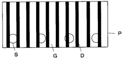
- continuous design printing D can be realized on a composite material having different printing characteristics including the snap portion S and the ground texture G.
- the flocculant supplied to the back surface, it is possible to prevent ink permeation when the back surface is printed by the print head 5, so that it is possible to realize design printing with different front and back sides.
- the ink droplet size sufficiently smaller than the thickness of the fabric, the ink can be aggregated before reaching the back surface by permeation. In this way, by controlling the presence or absence of the supply of the deactivator, it is possible to control the bleeding of the ink in the ground structure and the penetration into the back surface, thereby realizing different color development.
- Embodiment 2 As the printed material P used in the first embodiment, a plate-like resin material having different capillary force regions may be used. For example, as shown in FIG. 5, it is possible to use a printing material P in which a recess 21 is formed on a resin plate. When the concave portion 21 is formed on the resin plate, a difference in capillary force is generated between the convex portion 22 adjacent to the concave portion 21, and the ink supplied to the convex portion 22 easily moves to the adjacent concave portion 21. That is, the printing material P includes a concave portion 21 having a high capillary force and a convex portion 22 having a low capillary force.
- the edge portions on both sides of the bottom surface have a larger capillary force than the central portion of the concave portion, and ink droplets tend to collect at the edge portion.
- the flocculant is supplied from the flocculant supply device 4 to the printing material P. Since the flocculant is provided with a droplet size sufficiently smaller than the capillary force length, an ultrasonic atomizer or the like can be used.
- the ink containing the aggregate is supplied from the print head 6 to the concave portion 21 of the printed material P and the convex portion 22 adjacent thereto. In the convex portion 22, the aggregating agent and the aggregate to be contained in the ink undergo an agglutination reaction and gel.
- the ink is retained on the convex portion 22 by becoming a gel.
- the ink printed on the central portion of the concave portion 21 also stays at the printing position due to the aggregation reaction, and uniform printing can be realized without moving to the edge portion.
- the printed material P is heated by the heating device 7, and the ink remaining in the concave portions 21 and the convex portions 22 of the printed material P is vaporized and dyed.
- a printed material P in which regions having different wettability are formed on the resin plate and the region having high wettability has a low capillary force.
- a printed material P as shown in FIG. 6, a part of a resin plate is matted to reduce wettability, and has a matting region 23 having a high capillary force and a low capillary force. What consists of the surface 24 of a resin board can be used.
- the flocculant is supplied from the flocculant supply device 4 to the printing material P. Thereafter, the ink containing the aggregates is supplied from the print head 6 to the matted region 23 of the print target P and the surface 24 adjacent thereto.
- the aggregating agent and the aggregate to be contained in the ink undergo an agglutination reaction and gel.
- the ink is retained on the surface 24 by becoming a gel.
- the printing material P is heated by the heating device 7, and the ink remaining on the matting area 23 and the surface 22 of the printing material P is vaporized and dyed with a pigment.
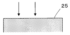
- the resin material having the wide surface 25 is easy to move the ink, and the ink moves and gathers in a part only by slightly different capillary force of the surface 25 of the resin material, and it is difficult to uniformly dye the entire surface 25.
- a flocculant and an ink containing an aggregate are supplied to the entire surface 25 of the printed material P to be gelled. Subsequently, the entire surface 25 of the printing material P can be uniformly dyed by heat-treating the printing material P in which the ink is gelled and fastened.
- a resin material composed of regions having different capillary forces can be easily dyed to a target color simply by gelling the ink.
- the ink ejected from the print heads 5 and 6 is one that is heat-treated by the heating device 7 and sublimated and transferred to the printing material P, but is not limited thereto.
- an ink that is contained in the ink by evaporation of the dispersion medium and in which the polymer component forms a film can be used.
- an ink for adhering the coloring material to the printing material P by including a component that is cured by energy irradiation such as heat or light to form a film.
- the film After supplying an ink using urethane acrylate or epoxy acrylate as a film forming component to the printing material P, the film is formed by subjecting the film forming component to radical polymerization by heat treatment and irradiation with energy such as ultraviolet rays. Color material can be adhered to P.
- the film After supplying ink using an epoxy resin prepolymer, urethane prepolymer, or the like as a film-forming component to the printed material P, the film is formed by reacting the film-forming component with heat treatment and coloring the printed material P. Can also be attached.
- an ink containing nano metal particles that become a film by heat treatment can be used. After supplying the ink to the printing material P, the nano metal particles contained in the ink are formed into a film on the printing material P by heat treatment, and a metal layer can be formed on the surface thereof.
- Embodiment 3 As shown in FIG. 8, a raised fabric made of a ground tissue having a high capillary force and a raised tissue having a low capillary force may be used as the printing material P used in the first embodiment.
- a deactivator is supplied to the ground structure from the back side of the printing material P by the deactivator supply device 3.
- the supplied quencher penetrates to the surface side of the ground tissue.
- a mist-like flocculant is supplied from the front side of the printing material P by the flocculant supply device 4.
- the flocculant supply device 4 adjusts the size and amount of the flocculant and supplies the flocculant, the flocculant supplied to the raised fabric is supplied at a size and interval at which the droplets do not coalesce.
- the print heads 5 and 6 eject ink onto the printing material P.
- the ink ejected from the print head 5 is supplied to the ground structure from the back side of the printing material P, the ink penetrates the ground structure as it is.
- the ink containing the aggregate to be ejected from the print head 6 is supplied to the surface side of the printed material P.
- the aggregate When ink containing an aggregate is supplied, the aggregate is gelled by an aggregating reaction with an aggregating agent present on the surface of the raised fabric. Thus, it becomes gel form, and ink is stopped by the raising part of a raising fabric.
- the quencher supplied to the ground texture from the deactivator supply device 3 avoids the agglomeration reaction between the two, so that the ink in the ground texture Does not stay gelled.
- the disperse dye used in the first embodiment is used as a color material, the printed matter P is heated by the heating device 7 as in the first embodiment, and the ink supplied to the ground structure is vaporized so that the pigment of the ink is formed.
- the ink that is dyed into the ground tissue and supplied to the raised fabric is gelled, and the pigment of the ink is dyed into the raised fabric.
- an acidic dye instead of a disperse dye as the color material, and dye nylon such as wool or wool as a printing material, or cotton as a printing material using a reactive dye.
- a steam process is desirable instead of the heat process.
- the side close to the tip of the raised portion is colored by the color material of the ink printed from the front side by the print head 6, and the side close to the ground structure is the color material from the back side by the print head 5. It can also be colored. It is possible to change the coloring degree of the front-end
- the printing apparatus of the present embodiment it is possible to easily dye a raised color composed of regions having different capillary forces into a target color simply by gelling the ink.
- Embodiment 4 As the printed material P used in Embodiment 1, a nonwoven fabric in which a large number of resin fibers such as polypropylene are randomly arranged in a planar shape may be used.
- the nonwoven fabric includes a region A in which the fiber density is arranged and a region B in which the fiber density is low, and the fiber density fluctuates.
- the region A having a high fiber density is more affected by the surface tension of the fiber than the region B having a low fiber density, so that the capillary force is increased.
- the ink droplets landed on the region B with low fiber density move to the region A with high fiber density.
- the droplets that have landed on the single fiber are not limited to the landing position, but move to a nearby fiber crossing position, that is, a position where the capillary force is higher than that of the single fiber.
- FIG. 13 shows the configuration of the printing apparatus according to the fourth embodiment.
- the printing apparatus according to the fourth embodiment is the same as the printing apparatus according to the first embodiment shown in FIG. 1 except that the flocculant supply apparatus 4 is provided on the surface side of the printing material P instead of the flocculant supply apparatus 4 and the deactivator.
- the supply device 3, the color material ink print head 6, the heating device 7 and the reduction cleaning device 8 are omitted.
- the flocculant is supplied onto the fibers of the printing material P from the flocculant supply device 4 a of the pretreatment unit 1.
- the aggregating agent for example, a cationic polymer is used.
- the printing material P is moved to the printing unit 2, and ink is ejected from the print head 5 onto the printing material P.
- the ink for example, an ink in which a pigment and an aqueous polymer are dispersed in an aqueous dispersion medium containing an anionic surfactant is used.
- the pigment and the aqueous polymer particles are dispersed in the aqueous dispersion medium in a stable state negatively charged by the anionic surfactant.
- an aqueous polymer for ink for example, a polymer containing polyolefin, polyurethane, acrylic, polyester, or the like can be used.
- the ink droplets that have landed on the area A of high fiber density or the area B of low fiber area of the printing medium P are cationic polymers in which aqueous polymer particles in the ink are present on the fibers of the printing medium P. And gels by agglutination reaction and remains in each region. In addition, a large amount of ink can remain on the printing surface of the printing material P.
- the ink aggregated on the fibers of the printing material P is dried by the drying device 9 to form a film of the aqueous polymer in the ink, and the colored polymer film incorporating the pigment is formed on the fibers of the printing material P. Formed.
- a print image can be formed on the printing material P only by the drying process by the drying device 9 without performing the cleaning process thereafter. it can.
- the printed material P is activated by corona treatment or plasma treatment before supplying the flocculant from the flocculant supply device 4a. It is desirable to keep it.
- Embodiment 5 As shown in FIG. 14, it is also possible to use, as the substrate to be printed P, a fiber bundle such as a woven fabric or a knitted fabric through which a region having a high capillary force passes from the front surface to the back surface.
- a yarn is constituted by a fiber bundle in which a plurality of polyester fibers, nylon fibers, cellulose fibers and the like having a diameter of 10 to 20 ⁇ m are gathered, and a woven fabric or a knitted fabric constituted by these yarns is used as the printing material P.
- a yarn composed of such a fiber bundle has a strong capillary force in a gap of several to several tens of microns between the fibers. For this reason, the ink droplets that have landed on the substrate to be printed penetrate and move along the fiber bundle and reach the back surface without staying. Therefore, as shown in FIG. 14, ink jet printing is performed only on a predetermined surface area F. It was difficult.
- fabrics and knitting used in the textile field, etc. require different functions on the inner side close to the skin (back surface area of the printed material) and the outer surface facing the outside (front surface area of the printed material). There is also.
- the inside needs to absorb moisture from sweat and to release heat by reacting with the moisture
- the outside is waterproof to prevent rain, etc., or the inside moisture appears as a stain.
- a water repellent function is required.
- the antistatic agent for preventing charging of the printed material and the water immersion treatment for increasing the moisture adsorption capacity of the fiber for each area.
- FIG. 15 shows a configuration of a printing apparatus according to the fifth embodiment.
- the printing apparatus according to the fifth embodiment is the same as the printing apparatus according to the first embodiment shown in FIG. 1 except that the flocculant supply device 4a is provided on the surface side of the printing material P instead of the flocculant supply device 4, and the quenching agent.
- the supply device 3 and the color material ink print head 6 are omitted.
- the flocculant is supplied from the flocculant supply device 4a of the pretreatment unit 1 to the surface of the printing material P.
- the printing material P is moved to the printing unit 2, and ink containing a coagulant and a processing agent for converting the physical properties of the printing material P is applied to the surface of the printing material P from the color material ink print head 5. It is ejected by the inkjet method.
- the processing agent is adjusted so as to be supplied in an amount of 10 to 150% of the weight of the printed material, preferably several tens of percent of the weight of the printed material.
- some processing agents convert the physical properties of the printed material P and function as an aggregating agent. When a processing agent having the function of an aggregating agent is used, ink containing only the processing agent is ejected. can do.
- the ink droplets ejected from the print head 5 land on the substrate P and then penetrate into the fiber bundle in the surface area F of the printing surface, and the aggregating agent in the ink is supplied to the substrate P in advance.
- the speed of the agglutination reaction can be controlled by changing the concentration or the like of the aggregating agent or the aggregating agent, so that the ink containing the processing agent can be penetrated from the surface of the printing material P to an appropriate depth.
- the ink containing the processing agent can be attached to the predetermined surface region F by controlling the penetration of the ink containing the processing agent with respect to the position and depth of the printing material P.
- the printing material P is subjected to a heating process by the heating device 7, a cleaning process by the reduction cleaning device 8, and a drying process by the drying device 9.
- the surface area F of the substrate P can be dyed and a desired function can be imparted by the action of the processing agent.
- an antistatic agent obtained by adding a surfactant or the like to an aqueous polymer aqueous solution such as polyvinyl alcohol, aqueous polyester or aqueous acrylic is used.
- an aqueous dispersion of water repellent particles such as a fluororesin, a silicone resin, and a wax can be used.
- the water-repellent treatment agent is deposited on the substrate P and then formed into a film by drying and heat treatment, and if it contains a crosslinking agent, it adheres firmly to the fiber surface by a crosslinking reaction and exhibits a water-repellent function over a long period of time. I can do it.
- an aggregating function can be imparted by adding aqueous polyester, aqueous acrylic or the like as the aggregating agent.
- the flocculant supply device 4a supplies the flocculant toward the surface of the printing material P and the ink is applied from the print head 5.
- the present invention is not limited to this.
- the flocculant may be supplied to the back surface of the printed material P and ink containing the flocculant and the processing agent may be ejected.
- the concentration or the like of the flocculant or the aggregating agent by changing the concentration or the like of the flocculant or the aggregating agent, the permeation area of the ink penetrating from the back surface of the printed material P to the surface is controlled, and the predetermined back surface area of the printed material P is dyed. A desired function can be imparted.
- coagulant supply devices 4 a and 4 b are provided on the front side and the back side of the printing material P, respectively, and print heads 5 and 6 are provided on the front side and the back side of the printing material P, respectively.
- ink containing the aggregating agent and the processing agent can be ejected onto the front and back surfaces of the printing material P, respectively.
- the front surface area and the back surface area of the printing material P can be dyed with different color materials and can have different functions.
- the flocculant supply device 4 a and the print head 5 are provided on the front side of the printing material P with respect to the traveling direction of the printing material P, and the rear surface of the printing material P is provided behind it.
- the flocculant supply device 4b and the print head 6 can also be provided on the side.
- the flocculant supply device 4b and the print head 6 are provided on the back surface side of the printing material P with respect to the traveling direction of the printing material P, and the flocculant supply device 4a is provided behind and on the front surface side of the printing material P.
- the print head 5 may be provided.
- a dispersion containing an anionic surfactant is used as a dispersion in which an aggregate is dispersed (aggregate dispersion), and an acid is used as the coagulant.
- Aggregation reaction can be performed.
- the anionic surfactant is dispersed in a state adjusted to be neutral or alkaline.
- an organic acid is added as an aggregating agent and becomes acidic, the degree of dissociation is reduced and aggregation occurs.
- the aqueous polymer contained in the flocculant aggregates and gels.
- fatty acid sodium, monoalkyl sulfate, alkyl polyoxyethylene sulfate, alkylbenzene sulfonate, monoalkyl phosphate, etc. can be used as anionic surfactants, and malonic acid, citric acid, acetic acid can be used as acids.
- Inorganic acids such as organic acids such as dilute hydrochloric acid can be used.
- an alkali agent such as sodium carbonate, sodium hydrogen carbonate, or caustic soda that suppresses acidification by an organic acid can be used.
- the agglomeration reaction may be performed by a reaction using an aggregate dispersion liquid dispersion-stabilized with an anionic surfactant and an organic cationic polymer, or an aggregate dispersion liquid dispersion-stabilized with a cationic surfactant.
- a reaction by a flocculant composed of an organic anionic polymer can be used.
- an anionic surfactant is negatively charged and dispersed, but when an organic cationic polymer is added as an aggregating agent, the charge is neutralized and aggregated to be gelled.
- a compound having an amino group (-NH2) such as ammonia or alkylamine and a compound having a guanidino group or biguanide group such as arginine, guanidine, or biguanide derivative having more nitrogen can be used.
- a polymer having an amino group or imino group in the side chain or main chain an aqueous polymer containing a synthetic polymer such as polyethyleneimine, polyvinylamine or polyallylamine, and a polyamino acid such as polyornithine or polylysine can be used.
- the stabilized anionic surfactant used as an aggregate a polyacrylamide partially hydrolyzed or a copolymer of acrylamide and sodium acrylate can be used as the stabilized anionic surfactant used as an aggregate.
- an inorganic aggregate and a cationic polymer aggregate Can be used. Accordingly, the water-soluble polymer contained in the aggregate is aggregated and gelled. Further, coagulation may be used for the aggregation reaction.
- neutralizing agents such as electrolytes or alcohols
- the flocculant When added, it becomes electrically neutral, and the repulsion between the colloidal particles disappears to cause aggregation. Along with this, the colloidal particles are aggregated and gelled.
- hydrophobic colloid and a hydrocolloid an aluminum salt (aluminum sulfate, polyaluminum chloride) or an iron salt (polyferric sulfate, ferric chloride) is used.
- the agglomerates contain a hydrophobic colloid or a hydrocolloid dispersed in an agglomerate dispersion, and can also undergo an agglutination reaction by using a hydrophobic colloid or a hydrophilic colloid neutralizer as an aggregating agent.
- the viscosity of the ink may be increased by utilizing a crosslinking reaction by an aggregating agent composed of an aggregate dispersion containing a crosslinkable polymer (monomer or oligomer) and a crosslinking initiator.
- a crosslinking reaction with a polyvinyl alcohol (PVA) resin solution and boric acid a urethane resin-based reaction that causes a chemical reaction by mixing a polyol having a hydroxyl group at a terminal and a urethane prepolymer having an isocyanate group at a terminal and a polyol, or
- An epoxy resin-based reaction that causes a reaction with a curing agent such as an amine to the epoxy resin prepolymer can be used.
- the agglomerate can be subjected to an agglutination reaction by using a cross-linkable polymer dispersed in an agglomerate dispersion and using a cross-linking initiator of a cross-linkable polymer as an aggregating agent.
- a flocculant that can provide the flocculant with a size equal to or less than the capillary force length and the radius of curvature of the printing material can be selected.
- the droplets after landing by a device capable of generating fine droplets, such as an ultrasonic atomizer and air spray, are sized so as to remain at the landing position including the united droplets as shown in FIG. Adjust and supply.
- a supply method in which the droplet size and position are controlled as shown in FIG. 9B by an ink jet method, a gravure roller coating method, or the like can also be employed.
- the flocculant and the agglomerated material can be realized so that the landing of the ink including the agglomerated material can be realized while the flocculant is held at the landing position.
- an ink jet apparatus that prints ink containing ink almost simultaneously. As shown in FIG. 10, by using an ink jet device 31 in which a flocculant and a color material ink print head are arranged close to each other or integrated, the landing position and time are made to coincide with each other, which is shorter than the droplet moving time. It can be gelled in time. The ink containing the aggregating agent or the aggregate can stay at the landing position without moving from the landing position to the region of high capillary force.
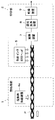
- Embodiment 6 As shown in FIG. 11, the printing unit used in the printing apparatus according to the first to fifth embodiments prints each area of the printing material P based on the input data and prints the results printed on the printing material P. It is possible to achieve a configuration that corrects by feedback and realizes a desired color.
- the printing unit 41 of the present embodiment includes a supply condition calculation unit 42, a printing characteristic database (DB) 43, a control unit 44, a print driving unit 45, and print heads 46 to 48.
- the supply condition calculation unit 42 includes information on the printed material P including a plurality of regions (for example, a ground tissue region and a raised tissue region) having different color development characteristics and a printed image to be printed on the printed material P.
- Information on the reproduction target color is input as input data by the operator.
- the information on the printing material P includes information such as the material / thickness, the presence / absence of the aggregate and the aggregating agent, and the type / amount of the aggregate and the aggregating agent for each area of the printing material.
- the information about the reproduction target color includes information on the chromaticity of the reproduction target color in each area of the substrate P, each pixel, color blur (spatial frequency), front / back uniformity, and the like.
- the supply condition calculation unit 42 is connected to the print characteristic DB 43.
- the supply condition calculation unit 42 searches the print characteristic DB 43 based on the information on the printing object P and the information on the reproduction target color, and print heads 46 to 46 showing the color development closest to the reproduction target color for each area of the printing object P.
- ink types, ink supply parameters, penetrant supply parameters, and pretreatment section conditions (deactivator, flocculant) are extracted.
- the supply parameters of the ink and the penetrating liquid include the voltage, frequency, waveform, and the like output to the print heads 46-48.
- the print characteristic DB 43 includes the relationship between the print amount of each color ink and the color development characteristics after completion of the color development process for each region. At this time, the relationship between color development characteristics (spatial frequency characteristics of printed image, uniformity of front and back colors) according to the presence / absence of addition of the aggregate and the aggregating agent or the amount of the aggregate and the aggregating agent is included.
- the “penetrating liquid” is a liquid for promoting permeation for appropriately penetrating the ink after printing into the printing material, and is preferably a dispersion medium constituting the ink. By printing “penetrating liquid”, the ink can reach the back surface of the printing object even when printing a small amount.
- the supply condition calculation unit 42 is connected to the control unit 44.
- the control unit 44 inputs an electric signal indicating the ink type, ink supply parameter, and permeating liquid supply parameter required for each region extracted by the supply condition calculation unit 42 to the print driving unit 45, so that the print object P is printed. Controls printing.
- the control unit 44 is connected to the print driving unit 45.
- the print drive unit 45 drives the print heads 46 to 48 in accordance with the electrical signal input from the control unit 44.
- the print drive unit 45 is connected to the print heads 46 to 48.
- the print heads 46 to 48 are so-called ink jet type print heads, which eject four types of ink Y, M, C, K or penetrating liquid.
- the print head 46 ejects ink from the front side of the substrate P, and the print head 47 ejects ink from the back side of the substrate P.
- the print head 48 ejects the penetrating liquid from the front side of the printing material P.
- the print head 47 ejects ink containing an aggregate to be printed P.
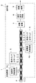
- a heating device 49, a reduction cleaning device 50, and a drying device 51 are arranged on the downstream side of the print heads 46 to 48 with respect to the moving direction of the printing material P, and the coloring material in the ink is fixed to the printing material P.
- a convex region measuring device 52 and a ground texture measuring device 53 are arranged downstream of the drying device 51 with respect to the traveling direction of the substrate P, and the convex region printing result measurement value input unit 54 is provided in the convex region measuring device 52.
- the convex area printing result measurement value input unit 54 and the ground texture printing result measurement value input unit 55 are connected to the supply condition calculation unit 42.
- the convex region measuring device 52 and the ground texture measuring device 53 are for measuring the optical characteristics from the convex region such as the raised portion of the printing material P and the ground texture, respectively, and measuring the color development amount.
- the convex region print result measurement value input unit 54 and the ground texture print result measurement value input unit 55 input the measurement values obtained in the convex region measurement device 52 and the ground texture measurement device 53 to the supply condition calculation unit 42.
- the printing result of the substrate P is fed back.
- the supply condition calculation unit 42 prints the supply condition values of the ink to be ejected and the penetrating liquid in which the measurement value input from the print result measurement value input unit 54 is corrected so as to realize the same color as the reproduction target color. This is obtained for each region of the object P.
- the supply condition calculation unit 42 searches the print characteristic DB 43 based on the information on the printing material P input by the operator and the information on the reproduction target color of the print image to be printed on the printing material P.
- the supply condition calculation unit 42 indicates a type similar to each region (for example, each region of the raised tissue to which the ground texture and the flocculant are added) on the printed material P from the printed material region type information in the printing characteristic DB 43. Search for each.
- the supply condition calculation unit 42 uses the data of the print characteristic DB 43 to predict color development when supplying supply parameters for all ink types of the print heads 46 and 47 and the penetrant liquid of the print head 48, and provides color development information. It is also possible to calculate and combine the supply parameters so that the coloring information becomes the coloring information target by an optimization method. Specifically, using the following formulas (3) and (4), K / S is used to obtain the relationship between the printing amount and the color development information, and the linear programming method by the simplex method, the successive approximation method, the genetic method, etc. Optimization techniques can be used. In addition, the supply condition calculation unit 42 can obtain a plurality of combinations of supply parameters close to the color reproduction target in the print characteristic DB 43 and obtain an optimum supply parameter by interpolation.
- K / S (1-Rc) 2 / 2Rc (3)
- (K / S) mix Jy (K / S) y + Jm (K / S) m + Jc (K / S) c + Jk (K / S) k (4)
- Formula (3) shows the relationship among the absorption intensity K by a color material, the light scattering intensity S from a to-be-printed object, and the reflectance Rc in each wavelength.
- (K / S) mix indicates K / S of a region where a plurality of color materials are printed and mixed
- (K / S) y, (K / S) m, (K / S) c and (K / S) k respectively indicate K / S when unit amounts of the four color materials are adhered
- Jy, Jm, Jc and Jk respectively indicate the four color materials on the printed material. Indicates the amount of adhesion.
- the ink type, ink supply parameter, and permeate supply parameter for each area of the printing material P extracted by the supply condition calculation unit 42 in this way are output to the control unit 44.
- the control unit 44 outputs the supply parameters of the ink and the penetrating liquid to the print drive unit 45
- the print drive unit 45 sends a drive signal corresponding to these supply parameters to the print heads 46 to 48 corresponding to the ink type or the penetrating liquid.
- the ink and the penetrating liquid are ejected onto each area of the printing material P.
- the target color can be reproduced with respect to each area even for a print object in which areas such as a ground structure having a high capillary force, a fastener element portion having a low capillary force, and a raised portion are combined.
- the coloring can be performed, and the uniformity in the thickness direction of the printing material P and the spatial frequency characteristics can be achieved as desired.
- ink and penetrating ink droplets are repeatedly applied to all regions with the ink and penetrant supply parameters extracted for each region of the substrate P.
- the printed object P that has been printed is heated by the heating device 49, then reduced and cleaned by the reduction cleaning device 50, and dried by the drying device 51.
- the dried printing material P is color-measured by the convex area measuring device 52 and the ground texture measuring apparatus 53, and the measured value is passed through the convex area printing result measured value input section 54 and the ground texture printing result measured value input section 55. Input to the supply condition calculation unit 42.
- the supply condition calculation unit 42 When the input measurement value is outside the allowable range of chromaticity of the reproduction target color, the supply condition calculation unit 42 performs measurement input from the convex region printing result measurement value input unit 54 and the ground texture printing result measurement value input unit 55. Ink and penetrant supply parameters to be ejected from the respective head portions of the print heads 46 to 48 are corrected so that the values match the chromaticity of the reproduction target color. The ink and penetrant supply parameters corrected by the supply condition calculation unit 42 are output to the control unit 44, and the control unit 44 uses the print driving unit 45 to set the print heads 46 to 48 on the basis of these supply parameters. The drive is controlled, and printing is performed on the substrate P.
- the correction does not fall within the allowable range of the chromaticity of the target color to be reproduced, it is preferable to repeat the above correction until it falls within the allowable range. If the input measurement values for the front / back uniformity and the spatial frequency are outside the allowable level of the target value, the supply condition of the preprocessing unit can be corrected to match the target value.
- the supply condition calculation unit 42 accumulates the supply parameter corrected by the feedback of the printing result in the print characteristic DB 43 every time it is corrected, or the supply already stored in the print characteristic DB 43 by the corrected supply parameter.
- a learning function can be provided by updating the parameters. As described above, the accuracy of information stored in the print characteristic DB 43 can be improved by learning each time printing is repeated.
- 1 Pretreatment section, 2, 41 printing section, 3 deactivator supply device, 4, 4a, 4b flocculant supply device, 5, 6, 46 to 48 print head, 7, 49 heating device, 8, 50 reduction cleaning device 9, 51 Drying device, 10 Ground texture, 11 Snap, 12 Cover, 21 Concave portion, 22 Convex portion, 23 Matting region, 24, 25 Surface, 31 Inkjet device, 42 Supply condition calculation unit, 43 Printing characteristic database, 44 Control unit, 45 printing drive unit, 52 convex area measuring device, 53 ground texture measuring device, 54 convex area printing result measured value input part, 55 ground texture printing result measured value input part, P printing object, G ground texture, S Snap part, D design printing.
Abstract
互いに異なる毛管力を有する複数の領域からなる被印字物全体を目標とする色で容易に染色することができる印字方法および印字装置を提供することにある。 凝集によりゲル化する被凝集体の凝集反応を促進させる凝集剤を凝集剤供給装置4が被印字物の少なくとも低い毛管力を有する領域に供給し、印字ヘッド6がインクジェット法で被凝集体を含むインクを被印字物の少なくとも低い毛管力を有する領域に向けて打滴し、被凝集体と凝集剤との凝集反応によりゲル化したインクを加熱装置7が被印字物に定着させる。
Description
この発明は、印字方法および印字装置に係り、特に、互いに異なる毛管力を有する複数の領域からなる被印字物をインクジェット方式で印字を行う方法および装置に関する。
インクジェット方式は、簡便な機構で高速に印字できることから広く普及し、紙だけでなく、布、織物、平滑樹脂表面などの様々な被印字物に対する印字が試みられている。近年では、これら被印字物の形態や素材も多様化しており、また同じ被印字物の中に異なる被印字特性を持つ複合材料への印字も求められてきた。このような被印字物についてどの領域についても思い通りの染色をすることが求められている。
被印字物の思い通りの発色を実現させるためには、着弾したインク滴が着弾位置に留まり制御可能なことが求められる。
被印字物に印字されたインク滴の性質は表面張力に基づく毛管力、毛管力長で特徴付けられる。液滴が表面張力で留まるサイズの指標を与える毛管力長(2)に比べ十分小さい(たとえば1/10)サイズのインク滴であれば平滑面上の着弾位置に留まることが可能であるが、印字密度が高くなり、インク滴が合一し毛管力長同等のサイズになる場合には、重力等の影響が大となり予測できない液滴の移動が生ずる。着弾位置が凸平面の場合、面の曲率が大きくなるとさらに移動しやすくなり、液滴の半径が曲率半径以下であることが望ましい。
毛管力は式(1)で示すように、表面張力に基づく液滴に働く力であり、細孔、糸内部、凹部等はインク保持の物質間距離(インクが保持される領域を構成する壁物質の間の平均的距離)rが小さくなるため毛管力が大となる。また濡れ性がよく接触角が小さな領域も毛管力が大となる。
p=aγcosθ/r ・・・(1)
なお、pは単位面積あたりの毛管力(圧力)、aは比例定数、γはインク液体の表面張力、θはインクと対象物質の間の濡れ性を示す接触角、rはインクを保持する物質間の距離である。
毛管力長は以下の式で表される。通常数1mm程度である。
1/κ=(γ/ρ・g)1/2 ・・・(2)
なお、1/κは毛管力長、γは表面張力、ρは比重、gは重力加速度を示す。
毛管力長より十分小さい液滴は、重力等外力の影響を受けることなく表面張力で着弾位置に留まることが出来る。液滴が合一し毛管力長同等あるいはそれ以上のサイズになると不安定になり予測不能な移動が始まる。特に近傍に地組織が存在する場合、地組織に対して低い毛管力しか働かないため着弾したインク滴は、高い毛管力を持つ地組織に移動してしまう。
織物からなる被印字物としては、例えば、織物の地組織にポリエステルからなるファスナー、ボタンを取り付けた織物、または、地組織の表面を毛羽立てた起毛織物などが存在する、ファスナーのスナップ、ボタン、起毛部分は打滴されたインク滴にとって平滑な凸形状をしており、インク滴は留まりにくい。また、平面形状の樹脂としては、例えば、プラスティックカード、樹脂成型品等がある。平面形状の樹脂板に凹凸が形成されたもの、または、樹脂板の一部にマット処理、親水処理を施したものなどが存在する。平面形状の樹脂が部分的に異なる毛管力を持つことになる。具体的には、樹脂板に形成された凹部やマット処理領域は高い毛管力を有する。
これらの被印字物の場合、低い毛管力によりインクが留まり難い領域(織物のスナップや起毛部分、樹脂板の表面)への印字が求められかつ、高い毛管力によりインクが留まり易い領域(織物の地組織、樹脂板の凹部やマット処理領域)が隣接して配置されている。このため、低い毛管力を有する領域に打滴したインクは高い毛管力を有する領域に移動し易く、所定のインク量を低い毛管力の領域に留めて目標とする色に染色することは困難であった。
そこで、例えば、特許文献1には、起毛織物において一様に染色し難い起毛部分の根元と先端でノズル口径を変えて異色に着色することで、その全体を目標とする色に染色することが提案されている。
しかしながら、ノズル口径の変更やインクの調整などに多大な労力を要する。
この発明は、このような従来の問題点を解消するためになされたもので、互いに異なる毛管力を有する複数の領域からなる被印字物全体にわたり目標とするインク着弾を実現し染色・着色の場合には目標の発色を容易に実現することができる印字方法および印字装置を提供することを目的とする。
上記目的を達成するために、本発明に係る印字方法は、低い毛管力によりインクが留まり難い領域を含む被印字物にインクジェット法により印字を行う印字方法であって凝集によりゲル化(コロイド粒子、水性分散ポリマー、水溶性ポリマー、界面活性剤、モノマー等の被凝集体が構造化し粘度があがること)する被凝集体の凝集反応を促進させる凝集剤を被印字物の少なくとも低い毛管力を有する領域に供給し、インクジェット法で前記被凝集体を含むインクを被印字物の少なくとも低い毛管力を有する領域に向けて打滴し、前記被凝集体と前記凝集剤との凝集反応によりゲル化したインクを被印字物に定着させるものである。
ここで、前記凝集剤は、被印字物の低い毛管力を有する領域に供給されたそれぞれの液滴が合一して供給位置から移動しないように、大きさ及び量を調整して毛管力長に比べ十分小さいサイズで供給されることが好ましい。また、前記凝集剤は液滴が合一しないような間隔で規則的に印字する、あるいはエアースプレー、霧化器等を使用し、毛管力長に比べ十分小さなサイズの液滴を生成し供給することができる。
また、前記被凝集体を含むインクは、被印字物の低い毛管力を有する領域に供給された前記凝集剤が被印字物の高い毛管力を有する領域に移動しないうちにゲル化するように供給することができる。
また、前記被凝集体を含むインクは、被印字物の低い毛管力を有する領域に供給された前記凝集剤が被印字物の高い毛管力を有する領域に移動しないうちにゲル化するように供給することができる。
また、前記凝集剤を供給する前に、前記凝集剤と前記被凝集体との凝集反応を失活させる失活剤を被印字物の高い毛管力を有する領域に供給することが可能である。
また、前記凝集剤は、被印字物の低い毛管力を有する領域にのみ供給することができる。
また、前記凝集剤は、被印字物の低い毛管力を有する領域にのみ供給することができる。
また、前記被凝集体は、酢酸ビニル系、アクリル系、ポリエステル系あるいはウレタン系等の水性ポリマー分散液、PVAあるいはアルギンサン等の水性ポリマー溶液、あるいは界面活性剤により微粒子を分散させたものを含むことが好ましい。
また、前記被凝集体分散液としてアニオン性界面活性剤を含む分散液を用いると共に前記凝集剤として有機酸を用いることで凝集反応を行うことができる。また、前記被凝集体分散液として有機カチオン性高分子を含む分散液を用いると共に前記凝集剤としてアニオン界面活性剤を用いて、または、前記被凝集体分散液として有機アニオン性高分子を含む分散液を用いると共に前記凝集剤としてカチオン界面活性剤を用いて凝集反応を行ってもよい。また、前記被凝集体分散液として疎水コロイドまたは親水コロイドを分散させたものを用いると共に前記凝集剤として前記疎水コロイドまたは前記親水コロイドの中和剤を用いることで凝集反応を行ってもよい。また、前記被凝集体分散液として架橋性ポリマーを含むものを用いると共に前記凝集剤として前記架橋性ポリマーの架橋開始剤を用いることで凝集反応を行ってもよい。
また、前記被凝集体分散液としてアニオン性界面活性剤を含む分散液を用いると共に前記凝集剤として有機酸を用いることで凝集反応を行うことができる。また、前記被凝集体分散液として有機カチオン性高分子を含む分散液を用いると共に前記凝集剤としてアニオン界面活性剤を用いて、または、前記被凝集体分散液として有機アニオン性高分子を含む分散液を用いると共に前記凝集剤としてカチオン界面活性剤を用いて凝集反応を行ってもよい。また、前記被凝集体分散液として疎水コロイドまたは親水コロイドを分散させたものを用いると共に前記凝集剤として前記疎水コロイドまたは前記親水コロイドの中和剤を用いることで凝集反応を行ってもよい。また、前記被凝集体分散液として架橋性ポリマーを含むものを用いると共に前記凝集剤として前記架橋性ポリマーの架橋開始剤を用いることで凝集反応を行ってもよい。
また、被印字物において低い毛管力を有する領域は、繊維織物基材から起毛された起毛組織からなることができる。また、被印字物において低い毛管力を有する領域は、繊維織物基材に取り付けられた、毛管力長サイズ以上のポリエステル等の樹脂からなる構造物からなることもできる。また、被印字物は不織布からなり、高い毛管力を有する領域は繊維の密度の高い領域からなることもできる。また、樹脂材からなる被印字物において凹部が形成され、前記凹部が高い毛管力を有する領域となると共に前記凹部に隣接する被印字物の表面が低い毛管力を有する領域となることもできる。また、樹脂材からなる被印字物において濡れ性の異なる領域が形成され、濡れ性の大きい領域が低い毛管力を有する領域となることもできる。
また、本発明に係る印字装置は、低い毛管力によりインクが留まり難い領域を含む被印字物にインクジェット法により印字を行う印字装置であって、凝集によりゲル化する被凝集体の凝集反応を促進させる凝集剤を被印字物の少なくとも低い毛管力を有する領域に供給する凝集剤供給装置と、インクジェット法で前記被凝集体を含むインクを被印字物の少なくとも低い毛管力を有する領域に向けて打滴するインク供給装置と、前記被凝集体と前記凝集剤との凝集反応によりゲル化した前記インクを被印字物に定着させる定着装置とを有するものである。
ここで、前記印字装置は、前記凝集剤供給装置により前記凝集剤を供給する前に、前記凝集剤と前記被凝集体との凝集反応を失活させる失活剤を被印字物の高い毛管力を有する領域に供給する失活剤供給装置をさらに有することが可能である。失活剤としては凝集反応が起こりにくいPh領域にシフトさせる、酸、アルカリ等が使用できる。たとえば凝集剤として有機酸を用い酸性領域で凝集を起こさせるアニオン性活性剤を主成分とする被凝集体分散液の場合、アルカリ剤が失活剤として使用できる。
また、前記凝集剤供給装置は、被印字物の低い毛管力を有する領域にのみ前記凝集剤を供給することが可能である。
また、前記凝集剤供給装置は、被印字物の低い毛管力を有する領域にのみ前記凝集剤を供給することが可能である。
また、本発明に係る印字方法は、表面から裏面にかけて高い毛管力によりインクが浸透し易い領域が延びる被印字物にインクジェット法により印字を行う印字方法であって、凝集によりゲル化する被凝集体の凝集反応を促進させる凝集剤を被印字物の表面領域および裏面領域のうち少なくとも一方の所定の領域に供給し、インクジェット法で被凝集体を含むインクを被印字物の前記所定の領域に向けて打滴し、前記被凝集体と前記凝集剤との凝集反応によりゲル化したインクを被印字物の前記所定の領域に定着させるものである。
ここで、凝集剤の供給が被印字物の表面領域および裏面領域に対してそれぞれ行われた後に、被凝集体を含むインクの打滴が被印字物の表面領域および裏面領域に対してそれぞれ行うことができる。また、被印字物の表面領域および裏面領域のうち一方の領域に対して凝集剤の供給および被凝集体を含むインクの打滴が行われた後に、被印字物の他方の領域に対して凝集剤の供給および被凝集体を含むインクの打滴が行うこともできる。
また、インクジェット法で被印字物に打滴される被凝集体を含むインクは、さらに被印字物の物性を変換する処理剤を含み、異なる種類の前記処理剤が被印字物の表面領域および裏面領域にそれぞれ供給されることにより、被印字物の表面領域および裏面領域を異なる物性に変換することが好ましい。また、前記処理剤としては、撥水剤を用いることができる。
また、インクジェット法で被印字物に打滴される被凝集体を含むインクは、さらに被印字物の物性を変換する処理剤を含み、異なる種類の前記処理剤が被印字物の表面領域および裏面領域にそれぞれ供給されることにより、被印字物の表面領域および裏面領域を異なる物性に変換することが好ましい。また、前記処理剤としては、撥水剤を用いることができる。
本発明によれば、毛管力の低い領域を含む被印字物、互いに異なる毛管力を有する複数の領域からなる被印字物についても各領域を目標とする色で容易に染色することができる。
以下に、添付の図面に示す好適な実施形態に基づいて、この発明を詳細に説明する。
実施形態1
図1に、本発明の実施形態1に係る印字装置の構成を示す。印字装置は、被印字物Pの前処理を行う前処理部1と被印字物Pに印字を行う印字部2とを有する。
ここで、被印字物Pは、例えば、高い毛管力を有してインクが留まり易いポリエステル繊維質の地組織と、この地組織より低い毛管力を有して地組織よりもインクが留まり難いポリエステルからなるファスナースナップ(スナップ)とから構成されるものとする。なお、毛管力とは、被印字物Pの各領域におけるインクを留める能力を示すものとし、高い毛管力を有する領域は、相対的に低い毛管力を有する周辺の領域から毛管力によりインクを集めることができ、低い毛管力を有する領域は、相対的に毛管力の強い周辺の領域からの引力でインクを保持することができない。
前処理部1は、被印字物Pに失活剤を供給する失活剤供給装置3と、被印字物Pに凝集剤を供給する凝集剤供給装置4とを有する。なお、失活剤とは凝集剤を失活させて凝集剤と被凝集体との凝集反応を生じさせないためのものであり、凝集剤と被凝集体とは互いに接触することで反応し凝集することで粘度が上昇する(ゲル化)ものである。
失活剤供給装置3は、被印字物Pのスナップがない裏面側に配置され、例えばインクジェット法により被印字物Pの地組織に失活剤を供給する。
凝集剤供給装置4は、被印字物Pのスナップがある表面側に配置され、被印字物Pの表面側に凝集剤を供給する。
凝集剤供給装置4により供給される凝集剤は、スナップの表面においてそれぞれの液滴が十分前述の式(2)で示される毛管力長及びスナップ表面の曲率半径以下のサイズであるという関係を保つよう凝集剤の供給密度、サイズとなる供給条件が選ばれる。その結果凝集剤は供給位置に留まり、被印字物Pの地組織に移動しないようにすることが出来る。
凝集剤供給装置4は、被印字物Pのスナップがある表面側に配置され、被印字物Pの表面側に凝集剤を供給する。
凝集剤供給装置4により供給される凝集剤は、スナップの表面においてそれぞれの液滴が十分前述の式(2)で示される毛管力長及びスナップ表面の曲率半径以下のサイズであるという関係を保つよう凝集剤の供給密度、サイズとなる供給条件が選ばれる。その結果凝集剤は供給位置に留まり、被印字物Pの地組織に移動しないようにすることが出来る。
凝集剤は、例えば10μm以下の大きさに調整される。凝集剤供給装置4には、凝集剤を数μm~数十μmほどのミスト状にして供給する超音波霧化器またはエアースプレー等が利用できる。あるいはインクジェットにより凝集剤が合一しないように間隔をあけて印字することも可能である。
被印字物Pの移動方向に対して前処理部1の下流側には、印字部2が配置されている。印字部2には、被印字物Pの移動方向に向かって、印字ヘッド5および6と、加熱装置7と、還元洗浄装置8と、乾燥装置9が順次配置されている。
印字ヘッド5は、被印字物Pの裏面側に配置され、地組織に対してインクジェット法によりインクを打滴するものである。一方、印字ヘッド6は、被印字物Pの表面側に配置され、被凝集体を含むインクを被印字物Pに打滴するものである。本実施例ではポリエステル繊維等の染色のため染色色材に分散染料を用い被凝集体と共にインクジェット用インクとして調整されたものを使用する。印字ヘッド6からスナップに供給された被凝集体を含むインクは、被凝集体と凝集剤が凝集反応することでゲル化してスナップの表面に留められる。また、印字ヘッド6から地組織に供給された被凝集体を含むインクは、失活剤により予め凝集剤が失活されているため被凝集体と凝集剤が凝集反応せず、ゲル化することなく地組織に浸透される。このため地組織に印字されたインクは浸透により裏面まで到達するので表裏均一な印字が可能である。裏面へのインクの浸透を助けるため、色材を含まない分散液からなる浸透液を必要量印字することも可能である。
加熱装置7は、被印字物Pを加熱処理することで、地組織に浸透したインクと共にスナップにゲル状で留まるインク中の分散染料を気化(昇華)して被印字物Pを染色するものである。還元洗浄装置8は、染色された被印字物Pを洗浄するものである。乾燥装置9は、洗浄された被印字物Pを乾燥して仕上げるためのものである。
次に、図1に示した印字装置の動作を説明する。
まず、図1に示されるように、被印字物Pが、図示しない移動装置により一定方向に移動される。被印字物Pには、例えば図2(A)および(B)に示されるような、高い毛管力を有する地組織10に低い毛管力を有するスナップ11を取り付けたものが用いられる。このように、被印字物Pは、地組織10とスナップ11が隣接して存在するため、そのままの状態でスナップ11にインクを打滴すると毛管力の差によりインクが地組織10に移動し、スナップ11を所定のインク量で染色させることが困難なものである。
被印字物Pが移動されて前処理部1に設置された失活剤供給装置3に到達すると、失活剤供給装置3は被印字物Pの裏面側から地組織10に対して失活剤を供給する。供給された失活剤は、地組織10の表面側まで浸透するが、毛管力の低いスナップ部には達しない。
失活剤が供給された被印字物Pが失活剤供給装置3から凝集剤供給装置4に到達すると、被印字物Pの表面側から凝集剤供給装置4によりミスト状の凝集剤が供給される。この時、凝集剤供給装置63は凝集剤の大きさ及び量を調整して供給するため、スナップ11に供給された凝集剤はそれぞれの液滴が合一せず、毛管力の大きな地組織10に移動することなくスナップ11に留まることが出来る。
続いて、被印字物Pは印字部2に移動し、印字ヘッド5および6からインクを打滴される。印字ヘッド5から打滴されたインクは、被印字物Pの裏面側から地組織10に供給されるとそのまま地組織10に浸透される。一方、印字ヘッド6から打滴された被凝集体を含むインクは、被印字物Pの表面側からスナップ11および地組織10に供給される。スナップ11に供給された被凝集体を含むインクは、被凝集体とスナップ11の表面上に存在する凝集剤との凝集反応によりゲル化する。このようにゲル状となることで、インクがスナップ11の表面に留められる。また、地組織10に供給された被凝集体を含むインクは、失活剤供給装置3から地組織10に供給された失活剤が被凝集体と凝集剤との凝集反応を未然に回避するため、地組織10にゲル化して留まらずにそのまま地組織に浸透される。
このように、インクをゲル状にすることにより、スナップ11に供給された所定量のインクを地組織10に移動させることなく留めることができる。
被印字物Pは、スナップ11にインクをゲル化して留めた状態で加熱装置7により加熱処理される。地組織10に供給されたインクは、加熱処理により気化されてインクの色素が地組織に染色される。また、スナップ11に供給されてゲル化されたインクも同様に、加熱処理により気化されてインクの色素がスナップ11に染色される。インクの色素が加熱定着された被印字物Pは還元洗浄装置8により洗浄されると共に乾燥装置9により乾燥されて、被印字物Pの染色が仕上げられる。
例えば、スナップ11がポリエステルからなる場合には、加熱装置7により180~200℃で色素が被印字物Pに加熱定着された後、還元洗浄装置8により被印字物Pを加熱アルカリ水で洗浄し、乾燥装置9で被印字物Pを乾燥させて仕上げることができる。
例えば、スナップ11がポリエステルからなる場合には、加熱装置7により180~200℃で色素が被印字物Pに加熱定着された後、還元洗浄装置8により被印字物Pを加熱アルカリ水で洗浄し、乾燥装置9で被印字物Pを乾燥させて仕上げることができる。
本実施形態の印字装置によれば、低い毛管力を有する領域に対し所定量のインクをゲル化して留めるだけで、低い毛管力を有する領域を備えた被印字物Pを目標とする色に容易に染色することができる。
なお、凝集剤供給装置4は凝集剤を被印字物Pのスナップ11のみに供給してもよい。例えば、図3に示すように、凝集剤供給装置4はスナップ11の外周を覆ってスナップ11にのみミスト状の凝集剤を供給するためのカバー12を有する構成とすることができる。また、凝集剤供給装置4が凝集剤を供給する方向を調整してスナップ11のみに凝集剤を供給してもよい。また、印字ヘッド6は、被凝集体を含むインクを被印字物Pのスナップ11のみに供給する構成とすることもできる。これにより、被印字物Pの地組織10に失活剤を供給しなくてもスナップ11のみにゲル化したインクを留めることができる。
また、被印字物Pの地組織10において被凝集体と凝集剤とを凝集反応させてゲル化したインクを留めても被印字物Pの染色に影響がなければ、失活剤供給装置3により被印字物Pの地組織10に失活剤を供給しなくてもよい。被印字物Pの表側から凝集剤と被凝集体を含むインクとが供給され、ゲル状となったインクが地組織10とスナップ11に留められる。その後、加熱装置7で加熱処理され、ゲル化したインクが気化して地組織10およびスナップ11のそれぞれにインクの色素が染色される。
また、印字ヘッド6から供給されたインクにより被印字物Pの地組織10を目標とする色に染色することができれば印字ヘッド5からインクを供給しなくてもよい。
また、印字ヘッド6から供給されたインクにより被印字物Pの地組織10を目標とする色に染色することができれば印字ヘッド5からインクを供給しなくてもよい。
また、失活剤供給装置3は、被印字物Pの裏面側で且つ凝集剤供給装置4と印字ヘッド6の間に配置してもよい。失活剤は、被印字物Pに凝集剤が供給された後で地組織10に供給され、凝集剤を失活させる。
また、失活剤供給装置3は、供給した失活剤により地組織10に供給された凝集剤を失活させることができれば被印字物Pの表面側に配置することができる。
また、失活剤供給装置3は、供給した失活剤により地組織10に供給された凝集剤を失活させることができれば被印字物Pの表面側に配置することができる。
本実施形態では地組織及びスナップ部全体に渡り均一な染色を実現する場合を説明した。そのため表裏均一に染色するため浸透現象を利用している。一方、図4に示すように、地組織部G及びスナップ部Sにわたり連続的なデザイン印字Dを行う場合、スナップ部Sに目標の着色を行うだけでなく、地組織Gに対してもインクのにじみ(浸透)を防止し印字位置にインクを留めることが求められる。この場合失活剤は使用せず、凝集剤を全面に供給することが有効である。地組織Gに印字されたインク滴も凝集剤と反応するため着弾後に凝集してゲル化するので、浸透によるにじみ無く着弾位置に留まる。
本発明により、スナップ部S、地組織Gからなる印字特性の異なる複合素材に連続的なデザイン印字Dが実現できる。
また、凝集剤を裏面にも供給することで印字ヘッド5による裏面印字時のインクの浸透を防止できるので表裏異なるデザイン印字を実現することも可能である。この場合、インク滴サイズを、織物の厚みに比べ十分小さくすることで、インクが浸透により裏面に到達する前に凝集させることが可能となる。
このように失活剤の供給の有無を制御することにより地組織のインクのにじみ、裏面への浸透を制御でき異なる発色を実現できる。
本発明により、スナップ部S、地組織Gからなる印字特性の異なる複合素材に連続的なデザイン印字Dが実現できる。
また、凝集剤を裏面にも供給することで印字ヘッド5による裏面印字時のインクの浸透を防止できるので表裏異なるデザイン印字を実現することも可能である。この場合、インク滴サイズを、織物の厚みに比べ十分小さくすることで、インクが浸透により裏面に到達する前に凝集させることが可能となる。
このように失活剤の供給の有無を制御することにより地組織のインクのにじみ、裏面への浸透を制御でき異なる発色を実現できる。
実施形態2
実施形態1で使用される被印字物Pとして、異なる毛管力の領域を有する板状の樹脂材を用いてもよい。
例えば、図5に示すような、樹脂板に凹部21が形成された被印字物Pを用いることができる。樹脂板に凹部21が形成されると、これに隣接する凸部22との間で毛管力に差が生じ、凸部22に供給されたインクは隣接する凹部21に移動し易くなる。すなわち、被印字物Pは、高い毛管力を有する凹部21と低い毛管力を有する凸部22とからなる。また凹部21の内部を見ると底面の両サイドのエッジ部分は凹部中央部に比べ毛管力が大きくエッジ部分にインク滴は集まりやすい。まず、凝集剤供給装置4から被印字物Pに凝集剤が供給される。凝集剤は液滴サイズが、毛管力長より十分小さいサイズで提供するため超音波霧化器等が使用できる。その後、印字ヘッド6から被凝集体を含むインクが被印字物Pの凹部21とこれに隣接する凸部22とに供給される。凸部22では、凝集剤とインクに含まれる被凝集体とが凝集反応してゲル化する。このようにゲル状となることで、インクが凸部22に留められる。凹部21の中央部に印字されたインクも凝集反応により印字位置に留まり、エッジ部に移動することなく均一な印字が実現できる。被印字物Pは、加熱装置7により加熱処理され、被印字物Pの凹部21および凸部22に留まるインクが気化されてそれぞれ染色される。
また、例えば、樹脂板に濡れ性の異なる領域を形成し、濡れ性の大きい領域が低い毛管力を有する被印字物Pを用いてもよい。このような被印字物Pとしては、図6に示すような、樹脂板の一部をマット化処理することで濡れ性を小さくし、高い毛管力を有するマット化領域23と低い毛管力を有する樹脂板の表面24からなるものを用いることができる。凝集剤供給装置4から被印字物Pに凝集剤が供給される。その後、印字ヘッド6から被凝集体を含むインクが被印字物Pのマット化領域23とこれに隣接する表面24に供給される。表面24では、凝集剤とインクに含まれる被凝集体とが凝集反応してゲル化する。このようにゲル状となることで、インクが表面24に留められる。被印字物Pは、加熱装置7により加熱処理され、被印字物Pのマット化領域23および表面22に留まるインクが気化されて色素でそれぞれ染色される。
また、例えば、図7に示すような、広い平坦な表面25を有する樹脂材を被印字物Pに用いてもよい。広い表面25を有する樹脂材はインクが移動し易く、樹脂材の表面25の毛管力が少し異なるだけでインクが移動して一部分に集まってしまい、表面25全体を均一に染色することが困難である。このような、被印字物Pの表面25全体に凝集剤と被凝集体を含むインクとを供給してゲル化させる。続いて、インクをゲル化して留めた被印字物Pを加熱処理することで、被印字物Pの表面25全体を均一に染色することができる。
本実施形態の印字装置によれば、互いに異なる毛管力を有する領域からなる樹脂材についてもインクをゲル化して留めるだけで目標とする色に容易に染色することができる。
なお、印字ヘッド5および6から打滴されるインクは、加熱装置7で加熱処理して被印字物Pに昇華転写されるものを用いたがこれに限られない。
例えば、分散媒が蒸発することでインク中に含まれていた、ポリマー成分が皮膜を形成するインクを用いることが出来る。ポリマー成分としてアクリル系、ポリエステル系等の水性ポリマーが色材と共に分散しているインクを利用できる。また熱、光等のエネルギー照射などにより硬化して皮膜形成する成分を含むことで色材を被印字物Pに付着させるインクを用いることができる。皮膜形成する成分としてウレタンアクリレートやエポキシアクリレートを用いたインクを被印字物Pに供給後、加熱処理すると共に紫外線などのエネルギー照射によって皮膜形成成分にラジカル重合を起こさせて皮膜形成し、被印字物Pに色材を付着させることができる。また、皮膜形成成分としてエポキシ樹脂プレポリマーやウレタンプレポリマー等を用いたインクを被印字物Pに供給後、加熱処理すると共に皮膜形成成分を反応させて皮膜形成し、被印字物Pに色材を付着させることもできる。
また、加熱処理により皮膜化するナノ金属粒子を含むインクを用いることもできる。被印字物Pにインクを供給後、加熱処理することでインクに含まれるナノ金属粒子が被印字物Pに皮膜化され、その表面に金属層を形成することができる。
実施形態3
図8に示すように、実施形態1で使用される被印字物Pとして、高い毛管力を有する地組織と低い毛管力を有する起毛組織からなる起毛織物を用いてもよい。失活剤供給装置3により被印字物Pの裏面側から失活剤が地組織に供給される。供給された失活剤は、地組織の表面側まで浸透する。次に、被印字物Pの表側から凝集剤供給装置4によりミスト状の凝集剤が供給される。この時、凝集剤供給装置4は凝集剤の大きさ及び量を調整して供給するため、起毛織物に供給された凝集剤はそれぞれの液滴が合一しないサイズ・間隔で供給される。
続いて、印字ヘッド5および6が被印字物Pにインクを打滴する。印字ヘッド5から打滴されたインクは、被印字物Pの裏面側から地組織に供給されるとそのまま地組織に浸透される。一方、印字ヘッド6から打滴された被凝集体を含むインクは、被印字物Pの表面側に供給される。被凝集体を含むインクが供給されると、被凝集体が起毛織物の表面上に存在する凝集剤と凝集反応することによりゲル化する。このようにゲル状となることで、インクが起毛織物の起毛部に留められる。なお、インクと凝集剤が起毛織物から地組織に移動した場合は、失活剤供給装置3から地組織に供給された失活剤が両者の凝集反応を未然に回避するため、地組織にインクがゲル化して留まることはない。
実施形態1で使用した分散染料を色材とした場合は、印字物Pは、実施形態1と同様に加熱装置7により加熱処理され、地組織に供給されたインクが気化されてインクの色素が地組織に染色されると共に起毛織物に供給されてゲル化されたインクが気化されてインクの色素が起毛織物に染色される。また、色材に分散染料の代わりに酸性染料を用い、被印字物としてナイロン、羊毛等を、あるいは反応染料を用い、被印字物として綿を染色することも出来る。この場合加熱処理に換えスチィーム処理が望ましい。
このような色材を用いて、起毛部の先端に近い側は、印字ヘッド6による表側から印字されたインクの色材により着色し、地組織に近い側は印字ヘッド5による裏側からの色材により着色することもできる。表裏の印字色材を制御することで起毛部の先端部と根元部の着色度合いを変えることが可能である。
本実施形態の印字装置によれば、互いに異なる毛管力を有する領域からなる起毛織物についてもインクをゲル化して留めるだけで目標とする色に容易に染色することができる。
実施形態4
実施形態1で使用される被印字物Pとして、ポリプロピレンのような樹脂繊維が平面状に多数ランダムに配置された不織布を用いてもよい。
一般的に、不織布には、図12に示すように、繊維の密度が高く配置された領域Aと、繊維の密度が低い領域Bが混在し、繊維密度の揺らぎが存在する。繊維密度の高い領域Aは、繊維密度の低い領域Bに比べ繊維の表面張力の影響を多く受けるため毛管力が高くなる。このような被印字物Pにインクジェット印字を行った場合、図12に示すように、繊維密度の低い領域Bに着弾したインク滴は繊維密度の高い領域Aに移動する。また、単独繊維の上に着弾した液滴は着弾位置に留まらずに近傍の繊維交差位置、すなわち単独繊維に比べ毛管力の高い位置に移動し濃度ムラとなりやすい。
図13に実施形態4に係る印字装置の構成を示す。実施形態4に係る印字装置は、図1に示した実施形態1における印字装置において、凝集剤供給装置4に代えて被印字物Pの表面側に凝集剤供給装置4aを備えると共に、失活剤供給装置3、色材インク印字ヘッド6、加熱装置7および還元洗浄装置8が除かれている。まず、前処理部1の凝集剤供給装置4aから凝集剤が被印字物Pの繊維上に供給される。凝集剤としては、例えばカチオン高分子が用いられる。また、被印字物Pに供給される凝集剤が繊維に均一に供給されるように、毛管力長より小さく、さらに繊維の直径以下の滴にして供給するのが望ましく、例えば、超音波霧化器、エアースプレー装置等がこの目的で使用できる。
続いて、被印字物Pは印字部2に移動され、印字ヘッド5から被印字物Pにインクが打滴される。インクとしては、例えばアニオン系界面活性剤を含む水系分散媒に顔料および水性ポリマーが分散しているものが用いられる。顔料および水性ポリマー粒子は、アニオン系界面活性剤によりマイナスに帯電した安定な状態で水系分散媒に分散されている。また、インク用水性ポリマーとしては、例えばポリオレフィン、ポリウレタン、アクリル、ポリエステル、等を含むポリマーが使用できる。
このようにして、被印字物Pの繊維密度の高い領域Aまたは繊維領域の低い領域Bに着弾したインク滴は、インク中の水性ポリマー粒子が被印字物Pの繊維上に存在するカチオン高分子と凝集反応してゲル化し、各領域内にそれぞれ留められる。また、被印字物Pの印字面に多くインクが留まるようにすることも出来る。
このようにして、被印字物Pの繊維密度の高い領域Aまたは繊維領域の低い領域Bに着弾したインク滴は、インク中の水性ポリマー粒子が被印字物Pの繊維上に存在するカチオン高分子と凝集反応してゲル化し、各領域内にそれぞれ留められる。また、被印字物Pの印字面に多くインクが留まるようにすることも出来る。
印字後は、乾燥装置9により被印字物Pの繊維上に凝集されたインクを乾燥させることでインク中の水性ポリマーが皮膜化し、顔料を取り込んだ着色ポリマーの被膜が被印字物Pの繊維上に形成される。このように、被印字物Pの繊維上にインクを被膜化した場合には、その後に洗浄処理を施すことなく、乾燥装置9による乾燥処理のみで被印字物Pに印字画像を形成することができる。
なお、不織布の多くの素材であるポリプロピレンと水性ポリマーとの密着力を高めるために、凝集剤供給装置4aから凝集剤を供給する前に、被印字物Pをコロナ処理またはプラズマ処理等により活性化しておくことが望ましい。
なお、不織布の多くの素材であるポリプロピレンと水性ポリマーとの密着力を高めるために、凝集剤供給装置4aから凝集剤を供給する前に、被印字物Pをコロナ処理またはプラズマ処理等により活性化しておくことが望ましい。
実施形態5
図14に示すように、被印字物Pとして、織物または編み物のような繊維束から構成され、表面から裏面にかけて高い毛管力を有する領域が貫通しているものを用いることもできる。例えば、直径10~20μmのポリエステル繊維、ナイロン繊維、セルロース繊維等が複数本寄り集まった繊維束で糸を構成し、これら糸により構成された織物、あるいは編み物が被印字物Pとして用いられる。
図14に示すように、被印字物Pとして、織物または編み物のような繊維束から構成され、表面から裏面にかけて高い毛管力を有する領域が貫通しているものを用いることもできる。例えば、直径10~20μmのポリエステル繊維、ナイロン繊維、セルロース繊維等が複数本寄り集まった繊維束で糸を構成し、これら糸により構成された織物、あるいは編み物が被印字物Pとして用いられる。
このような繊維束からなる糸は、繊維間の数~数十ミクロンの間隙が強い毛管力を持つようになる。このため、被印字物に着弾したインク滴は、繊維束に沿って浸透・移動し、留まることなく裏面まで到達されるため、図14に示すように、所定の表面領域Fのみにインクジェット印字することは困難であった。
また、テキスタイル分野等で使用される織物や編み物においては、肌に近い内側(被印字物の裏面領域)と外部に面している外側(被印字物の表面領域)で異なる機能が求められることもある。例えば、内側は汗の水分を吸収し、さらにその水分と反応して熱を放出する機能等が求められるのに対し、外側は雨等を防ぐような防水機能、あるいは内部の水分がシミとして見えないような撥水機能等が求められる。このように被印字物の表面領域と裏面領域を異なる物性にするためには、それぞれの領域について、被印字物の帯電を防止するための帯電防止剤、繊維の水分吸着能を高める浸水化処理剤、あるいは繊維の撥水性を高めるため撥水剤等の処理剤を繊維束内部に十分浸透させて各領域に含まれる繊維に付着させる必要がある。
また、テキスタイル分野等で使用される織物や編み物においては、肌に近い内側(被印字物の裏面領域)と外部に面している外側(被印字物の表面領域)で異なる機能が求められることもある。例えば、内側は汗の水分を吸収し、さらにその水分と反応して熱を放出する機能等が求められるのに対し、外側は雨等を防ぐような防水機能、あるいは内部の水分がシミとして見えないような撥水機能等が求められる。このように被印字物の表面領域と裏面領域を異なる物性にするためには、それぞれの領域について、被印字物の帯電を防止するための帯電防止剤、繊維の水分吸着能を高める浸水化処理剤、あるいは繊維の撥水性を高めるため撥水剤等の処理剤を繊維束内部に十分浸透させて各領域に含まれる繊維に付着させる必要がある。
図15に実施形態5に係る印字装置の構成を示す。実施形態5に係る印字装置は、図1に示した実施形態1における印字装置において、凝集剤供給装置4に代えて被印字物Pの表面側に凝集剤供給装置4aを備えると共に、失活剤供給装置3および色材インク印字ヘッド6が除かれている。
まず、前処理部1の凝集剤供給装置4aから凝集剤が被印字物Pの表面に供給される。続いて、被印字物Pは印字部2に移動され、色材インク印字ヘッド5から被凝集剤および被印字物Pの物性を変換するための処理剤を含むインクが被印字物Pの表面にインクジェット法で打滴される。なお、処理剤は、被印字物重量の10~150%の量、望ましくは被印字物重量の数十%の量が供給されるように調整されている。また、処理剤には被印字物Pの物性を変換すると共に被凝集剤として機能するものもあり、被凝集剤の機能を備えた処理剤を用いる場合には処理剤のみを含むインクを打滴することができる。
印字ヘッド5から打滴されたインク滴は、被印字物Pに着弾後、印字面の表面領域Fの繊維束内に浸透し、インク内の被凝集剤が予め被印字物Pに供給された凝集剤と凝集反応してゲル化することで、処理剤を含むインクが裏面まで浸透することなく表面領域F内に留められる。なお、凝集剤または被凝集剤の濃度等を変えることで凝集反応の速度を制御し、被印字物Pの表面から適切な深さにまで処理剤を含むインクを浸透させることができる。このようにして、処理剤を含むインクの浸透を被印字物Pの位置および深さに関して制御することで、処理剤を含むインクを所定の表面領域Fに付着させることが可能となる。
続いて、被印字物Pは、加熱装置7による加熱処理、還元洗浄装置8による洗浄処理、および乾燥装置9による乾燥処理が施される。これにより、被印字物Pの表面領域Fが染色されると共に処理剤の作用により所望の機能を付与することができる。
被印字物Pの繊維束に機能を付与するための処理剤には、例えば、帯電防止剤として、ポリビニルアルコール、水性ポリエステル、水性アクリル等の水性ポリマー水溶液に界面活性剤等を加えたものが使用でき、撥水剤として、フッ素樹脂、シリコーン樹脂、ワックス等の撥水性粒子の水分散液が使用できる。撥水処理剤は、被印字物Pに付着後、乾燥・加熱処理で皮膜化し、さらに架橋剤等を含む場合は架橋反応により強固に繊維表面に付着し長期間にわたり撥水機能を発現することが出来る。撥水性粒子分散液自身が被凝集剤として機能しない場合、被凝集剤として水性ポリエステル、水性アクリル等を加え被凝集機能を付与することも出来る。
なお、本実施形態において、被印字物Pの表面に向かって凝集剤供給装置4aから凝集剤を供給すると共に印字ヘッド5からインクを打適したが、これに限られず、被印字物Pの裏面側に凝集剤供給装置および印字ヘッドを備えることで被印字物Pの裏面に凝集剤を供給すると共に被凝集剤および処理剤を含むインクを打滴してもよい。同様にして、凝集剤または被凝集剤の濃度等を変えることで被印字物Pの裏面から表面に浸透するインクの浸透領域を制御し、被印字物Pの所定の裏面領域について、染色すると共に所望の機能を付与することができる。
また、被印字物Pの表面領域と裏面領域にそれぞれ異なる種類の処理剤および顔料等を含むインクを供給することもできる。例えば、図16に示すように、被印字物Pの表面側と裏面側にそれぞれ凝集剤供給装置4aおよび4bを備えると共に被印字物Pの表面側と裏面側にそれぞれ印字ヘッド5および6を備えることで、被印字物Pの表面および裏面にそれぞれ凝集剤を供給した後に、被印字物Pの表面および裏面にそれぞれ被凝集剤および処理剤を含むインクを打滴することができる。これにより、被印字物Pの表面領域と裏面領域がそれぞれ異なる色材で染色されると共にそれぞれ異なる機能を付与することができる。また、図17に示すように、被印字物Pの進行方向に対して、被印字物Pの表面側に凝集剤供給装置4aおよび印字ヘッド5を備え、その後方で且つ被印字物Pの裏面側に凝集剤供給装置4bおよび印字ヘッド6を備えることもできる。これにより、被印字物Pの表面に対して凝集剤の供給およびインクの打滴が行われた後に、被印字物Pの裏面に対して凝集剤の供給およびインクの打滴が行われる。なお、被印字物Pの進行方向に対して、被印字物Pの裏面側に凝集剤供給装置4bおよび印字ヘッド6を備え、その後方で且つ被印字物Pの表面側に凝集剤供給装置4aおよび印字ヘッド5を備える構成としてもよい。
また、被印字物Pの表面領域と裏面領域にそれぞれ異なる種類の処理剤および顔料等を含むインクを供給することもできる。例えば、図16に示すように、被印字物Pの表面側と裏面側にそれぞれ凝集剤供給装置4aおよび4bを備えると共に被印字物Pの表面側と裏面側にそれぞれ印字ヘッド5および6を備えることで、被印字物Pの表面および裏面にそれぞれ凝集剤を供給した後に、被印字物Pの表面および裏面にそれぞれ被凝集剤および処理剤を含むインクを打滴することができる。これにより、被印字物Pの表面領域と裏面領域がそれぞれ異なる色材で染色されると共にそれぞれ異なる機能を付与することができる。また、図17に示すように、被印字物Pの進行方向に対して、被印字物Pの表面側に凝集剤供給装置4aおよび印字ヘッド5を備え、その後方で且つ被印字物Pの裏面側に凝集剤供給装置4bおよび印字ヘッド6を備えることもできる。これにより、被印字物Pの表面に対して凝集剤の供給およびインクの打滴が行われた後に、被印字物Pの裏面に対して凝集剤の供給およびインクの打滴が行われる。なお、被印字物Pの進行方向に対して、被印字物Pの裏面側に凝集剤供給装置4bおよび印字ヘッド6を備え、その後方で且つ被印字物Pの表面側に凝集剤供給装置4aおよび印字ヘッド5を備える構成としてもよい。
また、実施形態1~5における凝集反応には、被凝集体が分散された分散液(被凝集体分散液)としてアニオン性界面活性剤を含む分散液を用いると共に凝集剤として酸を用いることで凝集反応を行うことができる。アニオン性界面活性剤は、中性あるいはアルカリ性に調整された状態で分散しているが、凝集剤として有機酸が加えられて酸性となるとその解離度が低くなって凝集する。これに伴い、凝集剤に含まれる水性ポリマーが凝集してゲル化される。なお、アニオン性界面活性剤としては脂肪酸ナトリウム、モノアルキル硫酸塩、アルキルポリオキシエチレン硫酸塩、アルキルベンゼンスルホン酸塩、モノアルキルリン酸塩などが利用でき、酸としては、マロン酸、クエン酸、酢酸等の有機酸、希塩酸などの無機酸が利用できる。また、失活剤としては有機酸による酸性化を抑制する炭酸ソーダ、炭酸水素ソーダ、または苛性ソーダなどのようなアルカリ剤が利用できる。
また、凝集反応には、アニオン界面活性剤で分散安定化した被凝集体分散液と有機カチオン性高分子からなる凝集剤による反応、または、カチオン界面活性剤で分散安定化した被凝集体分散液と有機アニオン性高分子からなる凝集剤による反応が利用できる。例えば、アニオン界面活性剤は、マイナスに帯電して分散しているが、凝集剤として有機カチオン性高分子が加えられると電荷を中和し、凝集してゲル化される。
凝集剤としてのカチオンポリマーとして、アンモニアやアルキルアミン等のアミノ基(-NH2)を有する化合物及び窒素を更に多く有するアルギニンやグアニジンあるいはビグアニド誘導体等のグアニジノ基やビグアニド基を持つ化合物を用いることができる。また、側鎖あるいは主鎖にアミノ基あるいはイミノ基をもつ高分子としては、ポリエチレンイミン、ポリビニルアミン、ポリアリルアミン等の合成高分子及びポリオルニチン、ポリリジン等のポリアミノ酸を含む水性ポリマーが使用できる。
アクリルアミドとN,N-ジメチルアミノエチルメタクリレートまたはN,N-ジメチルアミノエチルアクリレートモノマーとを共重合したN,N-ジメチルアミノエチルアクリレート系共重合物や、ポリビニルアミジン系高分子、両性高分子などが利用できる。一方、被凝集体として用いられる安定化したアニオン界面活性剤は、ポリアクリルアミドの部分加水分解したものまたはアクリルアミドとアクリル酸ナトリウムとを共重合したものなどが利用できる。
また、凝集反応には、特許0879782号に記載されたようなリグニンスルホン酸と無機被凝集体とで処理する方法、特許0946869号に記載されたようなアルカリ性物質の存在下でフェノール類とアルデヒド類との初期縮合物と無機被凝集体とを併用する方法、特許1125326号に記載されたようなフェノール性水酸基を有する有機物質と無機又は有機被凝集体とを併用する方法、特開昭57-019084号公報に記載されたようなタンニンおよびタンニン酸にて処理する方法、特開昭60-238193号公報に記載されたようなリグニンスルホン酸と無機被凝集体およびカチオン性高分子被凝集体とで処理する方法が利用できる。これに伴い、被凝集体に含まれる水溶性ポリマーが凝集してゲル化される。
また、凝集反応には凝析を利用してもよい。被凝集体分散液において電気的に同じ符号を帯びて互いに反発することで拡散する疎水コロイドまたは親水コロイドに対し、これらのコロイド粒子と反対の符号を帯びた中和剤(電解質またはアルコールなど)からなる凝集剤を加えることで電気的中性となり、コロイド粒子間の反発が消滅することで凝集する。これに伴い、コロイド粒子が凝集してゲル化される。なお、疎水コロイドおよび親水コロイドとしては、アルミニウム塩(硫酸アルミニウム、ポリ塩化アルミニウム)や鉄塩(ポリ硫酸第二鉄、塩化第二鉄)が用いられる。また、前記被凝集体は、被凝集体分散液に分散させた疎水コロイドまたは親水コロイドを含むと共に凝集剤として疎水コロイドまたは親水コロイドの中和剤を用いることで凝集反応を行うこともできる。
また、凝集反応には凝析を利用してもよい。被凝集体分散液において電気的に同じ符号を帯びて互いに反発することで拡散する疎水コロイドまたは親水コロイドに対し、これらのコロイド粒子と反対の符号を帯びた中和剤(電解質またはアルコールなど)からなる凝集剤を加えることで電気的中性となり、コロイド粒子間の反発が消滅することで凝集する。これに伴い、コロイド粒子が凝集してゲル化される。なお、疎水コロイドおよび親水コロイドとしては、アルミニウム塩(硫酸アルミニウム、ポリ塩化アルミニウム)や鉄塩(ポリ硫酸第二鉄、塩化第二鉄)が用いられる。また、前記被凝集体は、被凝集体分散液に分散させた疎水コロイドまたは親水コロイドを含むと共に凝集剤として疎水コロイドまたは親水コロイドの中和剤を用いることで凝集反応を行うこともできる。
また、凝集反応には、架橋性ポリマー(モノマー、オリゴマー)を含む被凝集体分散液と架橋開始剤からなる凝集剤による架橋反応を利用してインクの粘度を上昇させてもよい。例えば、ポリビニルアルコール(PVA)樹脂溶液とホウ酸による架橋反応、末端に水酸基を持つポリオールと末端にイソシアネート基を持つウレタンプレポリマーとポリオールを混合することで化学反応を起こすウレタン樹脂系の反応、またはエポキシ樹脂プレポリマーにアミンなどの硬化剤による反応を起こすエポキシ樹脂系の反応等が利用できる。また、前記被凝集体は、被凝集体分散液に分散させた架橋性ポリマーを含むものを用いると共に凝集剤として架橋性ポリマーの架橋開始剤を用いることで凝集反応を行うこともできる。
また、実施形態1~5における凝集剤供給装置は、凝集剤を毛管力長及び被印字物の曲率半径以下のサイズで提供できるものが選択できる。超音波霧化器、エアースプレー等微細液滴を発生できる装置により着弾後の液滴が、図9(A)に示すように合一した液滴も含め着弾位置に留まるようなサイズになるよう調整して供給する。また、インクジェット法、グラビアローラ塗布等の方法で、図9(B)に示すように液滴サイズ及び位置を制御した供給法も採用できる。
また、実施形態1~5における凝集剤供給装置および印字ヘッドの代わりに、凝集剤が着弾位置に保持されている間に被凝集体を含むインクの着弾が実現できるよう、凝集剤と被凝集体を含むインクとをほぼ同時に印字するインクジェット装置を用いることも出来る。図10に示すように、凝集剤と色材インクの印字ヘッドを近接して配置あるいは一体化して設けたインクジェット装置31を用いることで着弾位置・時間を一致させ、液滴の移動時間に比べ短時間でゲル化させることが出来る。凝集剤あるいは被凝集体を含むインクが着弾位置から高い毛管力の領域に移動することなく着弾位置に留まることが出来る。
また、実施形態1~5における凝集剤供給装置および印字ヘッドの代わりに、凝集剤が着弾位置に保持されている間に被凝集体を含むインクの着弾が実現できるよう、凝集剤と被凝集体を含むインクとをほぼ同時に印字するインクジェット装置を用いることも出来る。図10に示すように、凝集剤と色材インクの印字ヘッドを近接して配置あるいは一体化して設けたインクジェット装置31を用いることで着弾位置・時間を一致させ、液滴の移動時間に比べ短時間でゲル化させることが出来る。凝集剤あるいは被凝集体を含むインクが着弾位置から高い毛管力の領域に移動することなく着弾位置に留まることが出来る。
実施形態6
図11に示されるように、実施形態1~5に係る印字装置で用いられた印字部は、入力データに基づいて被印字物Pの各領域を印字すると共に被印字物Pに印字した結果をフィードバックすることにより補正し目的の発色を実現するような構成にすることができる。
図11に示されるように、実施形態1~5に係る印字装置で用いられた印字部は、入力データに基づいて被印字物Pの各領域を印字すると共に被印字物Pに印字した結果をフィードバックすることにより補正し目的の発色を実現するような構成にすることができる。
本実施形態の印字部41は、供給条件演算部42と、印字特性データベース(DB)43と、制御部44と、印字駆動部45と、印字ヘッド46~48とを有する。
供給条件演算部42には、互いに異なる発色特性を有する複数の領域(例えば、地組織の領域および起毛組織の領域)からなる被印字物Pの情報および被印字物Pに印字しようとする印字画像の再現目標色、の情報が入力データとしてオペレータにより入力される。被印字物Pの情報としては、被印字物の領域ごとに素材・厚み、被凝集体と凝集剤の有無、被凝集体と凝集剤の種類・量等の情報が含まれる。再現目標色の情報には、被印字物Pの各領域、各画素における再現目標色の色度、色のにじみ(空間周波数)、表裏均一度、などに関する情報が含まれる。
供給条件演算部42は、印字特性DB43と接続されている。供給条件演算部42は、被印字物Pの情報および再現目標色の情報に基づいて印字特性DB43を検索し、被印字物Pの領域ごとに再現目標色に最も近い発色を示す印字ヘッド46~48のインク種、インク供給パラメータ、浸透液供給パラメータおよび前処理部条件(失活剤、凝集剤)、を抽出する。ここで、インクおよび浸透液の供給パラメータとしては、印字ヘッド46~48に出力する電圧、周波数、波形などが含まれる。印字特性DB43には、領域ごとに各色のインクの印字量と発色処理完了後の発色特性の関係が含まれる。このとき被凝集体と凝集剤の付与の有無、あるいは被凝集体および凝集剤の量等に応じた発色特性(印字画像の空間周波数特性、表裏色の均一度)の関係が含まれる。
ここで、「浸透液」は、印字後のインクを適切に被印字物内に浸透させるための浸透を促進するための液でありインクを構成する分散媒であることが好ましい。「浸透液」の印字により少量印字時にもインクが被印字物の裏面にまで到達することが可能となる。
供給条件演算部42は、制御部44と接続されている。制御部44は、供給条件演算部42で抽出された領域ごとに必要なインク種、インク供給パラメータおよび浸透液供給パラメータを示す電気信号を印字駆動部45に入力することで、被印字物Pへの印字を制御する。
制御部44は、印字駆動部45と接続されている。印字駆動部45は、制御部44から入力された電気信号に応じて印字ヘッド46~48をそれぞれ駆動する。
印字駆動部45は、印字ヘッド46~48と接続されている。印字ヘッド46~48は、いわゆるインクジェット方式の印字ヘッドであり、4種類のインクY,M,C,Kまたは浸透液を打滴する。印字ヘッド46は被印字物Pの表側から、印字ヘッド47は被印字物Pの裏側からそれぞれインクを打滴するものである。一方、印字ヘッド48は、被印字物Pの表側から浸透液を打滴するものである。なお、印字ヘッド47は、被凝集体を含むインクを被印字物Pに打滴するものである。
制御部44は、印字駆動部45と接続されている。印字駆動部45は、制御部44から入力された電気信号に応じて印字ヘッド46~48をそれぞれ駆動する。
印字駆動部45は、印字ヘッド46~48と接続されている。印字ヘッド46~48は、いわゆるインクジェット方式の印字ヘッドであり、4種類のインクY,M,C,Kまたは浸透液を打滴する。印字ヘッド46は被印字物Pの表側から、印字ヘッド47は被印字物Pの裏側からそれぞれインクを打滴するものである。一方、印字ヘッド48は、被印字物Pの表側から浸透液を打滴するものである。なお、印字ヘッド47は、被凝集体を含むインクを被印字物Pに打滴するものである。
被印字物Pの移動方向に対し、印字ヘッド46~48の下流側には、加熱装置49、還元洗浄装置50、および乾燥装置51が配置され、インク中の色材を被印字物Pに定着させる。
また、被印字物Pの進行方向に対し、乾燥装置51の下流側には凸領域計測装置52および地組織計測装置53が配置され、凸領域計測装置52に凸領域印字結果計測値入力部54を地組織計測装置53に地組織印字結果計測値入力部55をそれぞれ接続すると共に、凸領域印字結果計測値入力部54および地組織印字結果計測値入力部55を供給条件演算部42に接続する。
凸領域計測装置52および地組織計測装置53は、被印字物Pの起毛部のような凸領域および地組織からそれぞれ光学特性を計測し、発色量を測定するためのものであり、積分球を有する分光測色器または分光測色器で校正した光学センサーなどから構成される。パターンを印字する場合には、インクのにじみに相当する空間周波数特性を計測する光学センサーが用意されていることが望ましい。凸領域印字結果計測値入力部54および地組織印字結果計測値入力部55は、凸領域計測装置52および地組織計測装置53において得られた計測値を供給条件演算部42に入力することで、被印字物Pの印字結果をフィードバックするものである。供給条件演算部42は、印字結果計測値入力部54から入力された計測値が再現目標色と同様の発色を実現するように補正した打滴すべきインクおよび浸透液の供給条件値を被印字物Pの各領域について求めるものである。
凸領域計測装置52および地組織計測装置53は、被印字物Pの起毛部のような凸領域および地組織からそれぞれ光学特性を計測し、発色量を測定するためのものであり、積分球を有する分光測色器または分光測色器で校正した光学センサーなどから構成される。パターンを印字する場合には、インクのにじみに相当する空間周波数特性を計測する光学センサーが用意されていることが望ましい。凸領域印字結果計測値入力部54および地組織印字結果計測値入力部55は、凸領域計測装置52および地組織計測装置53において得られた計測値を供給条件演算部42に入力することで、被印字物Pの印字結果をフィードバックするものである。供給条件演算部42は、印字結果計測値入力部54から入力された計測値が再現目標色と同様の発色を実現するように補正した打滴すべきインクおよび浸透液の供給条件値を被印字物Pの各領域について求めるものである。
次に、図11に示した印字部41の動作を説明する。
まず、供給条件演算部42が、オペレータにより入力された被印字物Pの情報および被印字物Pに印字しようとする印字画像の再現目標色の情報に基づき、印字特性DB43を検索する。供給条件演算部42は、印字特性DB43の被印字物領域種情報から被印字物Pにおける各領域(例えば地組織および凝集剤を付与された起毛組織の各領域)と同様の種類を示すものをそれぞれ検索する。
供給条件演算部42は、印字特性DB43のデータを用い、被印字物Pの各領域の発色情報が発色情報目標となるような、印字ヘッド46及び47の全インク種(YMCK×2=8種)、印字ヘッド48の浸透液についての供給パラメータ、および前処理部条件(失活剤、凝集剤)を求める。
なお、供給条件演算部42は、印字特性DB43のデータを用い、印字ヘッド46及び47の全インク種および印字ヘッド48の浸透液についての供給パラメータを与えたときの発色を予測し、発色情報を計算し、発色情報が発色情報目標になるような供給パラメータの組み合わせを最適化手法で求めることも出来る。具体的には下記式(3)および(4)を使用してK/Sを利用し、印字量と発色情報の関係を求め、シンプレックス法による線形計画法、逐次近似法、遺伝的方法等の最適化手法が使用できる。また、供給条件演算部42は、印字特性DB43の中の発色再現目標に近い供給パラメータの組み合わせを複数求めそれらの補間により最適な供給パラメータを求めることも出来る。
K/S=(1-Rc)2/2Rc ・・・ (3)
(K/S)mix
=Jy(K/S)y+Jm(K/S)m+Jc(K/S)c+Jk(K/S)k ・・・ (4)
(K/S)mix
=Jy(K/S)y+Jm(K/S)m+Jc(K/S)c+Jk(K/S)k ・・・ (4)
なお、式(3)は各波長において、色材による吸収強度K、被印字物からの光散乱強度S、反射率Rcの関係を示す。また、式(4)において、(K/S)mixは複数の色材が印字され混合された領域のK/Sを示し、(K/S)y、(K/S)m、(K/S)c、(K/S)kはそれぞれ4色の色材が単位量付着したときのK/Sを示し、Jy、Jm、Jc、Jkはそれぞれ4色の色材の被印字物への付着量を示す。
このようにして供給条件演算部42で抽出された被印字物Pの領域ごとのインク種、インク供給パラメータおよび浸透液供給パラメータは、制御部44に出力される。制御部44は、印字駆動部45にインクおよび浸透液の供給パラメータを出力すると、印字駆動部45は、これら供給パラメータに応じた駆動信号をインク種または浸透液に対応する印字ヘッド46~48のヘッド部にそれぞれ出力し、被印字物Pの各領域にインクおよび浸透液を打滴する。
これにより、インクが高い毛管力を持つ地組織、低い毛管力を持つファスナーエレメント部、起毛部等の領域が複合している被印字物に対しても、それぞれの領域に対して再現目標色と同様に発色させることができると共に被印字物Pの厚み方向の均一度、空間周波数特性についても目標どおりの発色を実現できる。
これにより、インクが高い毛管力を持つ地組織、低い毛管力を持つファスナーエレメント部、起毛部等の領域が複合している被印字物に対しても、それぞれの領域に対して再現目標色と同様に発色させることができると共に被印字物Pの厚み方向の均一度、空間周波数特性についても目標どおりの発色を実現できる。
被印字物Pの移動に連動し、被印字物Pの領域ごとに抽出されたインクおよび浸透液の供給パラメータでインクおよび浸透液の打滴が全ての領域について繰り返し行われていく。印字された被印字物Pは、加熱装置49で加熱された後、還元洗浄装置50で還元洗浄され、乾燥装置51で乾燥される。乾燥された被印字物Pは凸領域計測装置52および地組織計測装置53により測色され、その計測値が凸領域印字結果計測値入力部54および地組織印字結果計測値入力部55を介して供給条件演算部42に入力される。
入力された計測値が再現目標色の色度の許容範囲外の場合、供給条件演算部42は、凸領域印字結果計測値入力部54および地組織印字結果計測値入力部55から入力された計測値が再現目標色の色度に一致するように、印字ヘッド46~48の各ヘッド部から打滴すべきインクおよび浸透液の供給パラメータをそれぞれ補正する。供給条件演算部42により補正されたインクおよび浸透液の供給パラメータは制御部44に出力され、制御部44がこれらの供給パラメータに基づいて印字駆動部45による印字ヘッド46~48の各ヘッド部の駆動を制御し、被印字物Pに印字される。なお、1度の補正で再現目標色の色度の許容範囲内に入らない場合には、許容範囲内に入るまで上記の補正を繰り返すことが好ましい。
表裏均一度、空間周波数についても入力された計測値が目標値の許容レベル外の場合、前処理部の供給条件を補正し目標値に合わせることができる。
表裏均一度、空間周波数についても入力された計測値が目標値の許容レベル外の場合、前処理部の供給条件を補正し目標値に合わせることができる。
このように、被印字物Pに印字した結果をフィードバックすることにより補正されたインクおよび浸透液の供給パラメータに基づき再び被印字物Pに印字するため、初期の計算精度が悪い場合、あるいはインク、被印字物P等の物性が経時あるいは環境で変化した場合であっても、発色量のズレあるいは変動を効果的に抑制することができる。
なお、供給条件演算部42は、印字結果のフィードバックにより補正された供給パラメータを、補正の都度、印字特性DB43に蓄積する、あるいは、補正された供給パラメータにより印字特性DB43に既に格納されている供給パラメータを更新することによって、学習機能を持たせることもできる。このように印字を繰り返すごとに学習させることで印字特性DB43に格納されている情報の精度を高めていくことができる。
1 前処理部、2,41 印字部、3 失活剤供給装置、4,4a,4b 凝集剤供給装置、5,6,46~48 印字ヘッド、7,49 加熱装置、8,50 還元洗浄装置、9,51 乾燥装置、10 地組織、11 スナップ、12 カバー、21 凹部、22 凸部、23 マット化領域、24,25 表面、31 インクジェット装置、42 供給条件演算部、43 印字特性データベース、44 制御部、45 印字駆動部、52 凸領域計測装置、53 地組織計測装置、54 凸領域印字結果計測値入力部、55 地組織印字結果計測値入力部、P 被印字物、G 地組織、S スナップ部、D デザイン印字。
Claims (25)
- 低い毛管力によりインクが留まり難い領域を含む被印字物にインクジェット法により印字を行う印字方法であって、
凝集によりゲル化する被凝集体の凝集反応を促進させる凝集剤を被印字物の少なくとも低い毛管力を有する領域に供給し、
インクジェット法で前記被凝集体を含むインクを被印字物の少なくとも低い毛管力を有する領域に向けて打滴し、
前記被凝集体と前記凝集剤との凝集反応によりゲル化したインクを被印字物に定着させることを特徴とする印字方法。 - 前記凝集剤は、被印字物の低い毛管力を有する領域に供給されたそれぞれの液滴が低い毛管力を有する領域において移動しないように、前記凝集剤の大きさ及び量を調整して供給されることを特徴とする請求項1に記載の印字方法。
- 前記凝集剤は、霧化することにより大きさ及び量を調整して供給されることを特徴とする請求項2に記載の印字方法。
- 前記被凝集体を含むインクは、被印字物の低い毛管力を有する領域に供給された前記凝集剤が被印字物の低い毛管力を有する領域において移動しないうちにゲル化するように供給されることを特徴とする請求項1に記載の印字方法。
- 前記凝集剤を供給する前に、前記凝集剤と前記被凝集体との凝集反応を失活させる失活剤を被印字物の高い毛管力を有する領域に供給することを特徴とする請求項1~4のいずれかに記載の印字方法。
- 前記凝集剤は、被印字物の低い毛管力を有する領域にのみ供給されることを特徴とする請求項1~4のいずれかに記載の印字方法。
- 前記被凝集体を含むインクを被印字物に供給すると共に、前記被凝集体を含まないインクを被印字物の高い毛管力を有する領域に向けて打滴することを特徴とする請求項1~6のいずれかに記載の印字方法。
- 前記被凝集体は、被凝集体分散液に分散させた水性ポリマーを含み、前記凝集剤により凝集し粘度が上昇することを特徴とする請求項1~7のいずれかに記載の印字方法。
- 前記被凝集体は、被凝集体分散液に分散させたアニオン性界面活性剤を含むと共に前記凝集剤として酸を用いることで凝集反応を行うことを特徴とする請求項1~7のいずれかに記載の印字方法。
- 前記被凝集体は、被凝集体分散液に分散させた有機カチオン性高分子を含むと共に前記凝集剤としてアニオン界面活性剤を用いて、または、前記被凝集体は、被凝集体分散液に分散させた有機アニオン性高分子を含むと共に前記凝集剤としてカチオン界面活性剤を用いて凝集反応を行うことを特徴とする請求項1~7のいずれかに記載の印字方法。
- 前記被凝集体は、被凝集体分散液に分散させた疎水コロイドまたは親水コロイドを含むものを用いると共に前記凝集剤として前記疎水コロイドまたは前記親水コロイドの中和剤を用いることで凝集反応を行うことを特徴とする請求項1~7のいずれかに記載の印字方法。
- 前記被凝集体は、被凝集体分散液に分散させた架橋性ポリマーを含むものを用いると共に前記凝集剤として前記架橋性ポリマーの架橋開始剤を用いることで凝集反応を行うことを特徴とする請求項1~7のいずれかに記載の印字方法。
- 被印字物において低い毛管力を有する領域は、起毛組織からなることを特徴とする請求項1~12のいずれかに記載の印字方法。
- 被印字物において低い毛管力を有する領域は、ポリエステル構造物からなることを特徴とする請求項1~12のいずれかに記載の印字方法。
- 被印字物は不織布からなり、高い毛管力を有する領域は繊維の密度の高い領域からなることを特徴とする請求項1~12のいずれかに記載の印字方法。
- 平滑な樹脂材からなる被印字物において凹部が形成され、前記凹部が高い毛管力を有する領域となると共に前記凹部に隣接する被印字物の表面が低い毛管力を有する領域となることを特徴とする請求項1~12のいずれかに記載の印字方法。
- 平滑な樹脂材からなる被印字物において濡れ性の異なる領域が形成され、濡れ性の大きい領域が低い毛管力を有する領域となることとを特徴とする請求項1~12のいずれかに記載の印字方法。
- 低い毛管力によりインクが留まり難い領域を含む被印字物にインクジェット法により印字を行う印字装置であって、
凝集によりゲル化する被凝集体の凝集反応を促進させる凝集剤を被印字物の少なくとも低い毛管力を有する領域に供給する凝集剤供給装置と、
インクジェット法で前記被凝集体を含むインクを被印字物の少なくとも低い毛管力を有する領域に向けて打滴するインク供給装置と、
前記被凝集体と前記凝集剤との凝集反応によりゲル化した前記インクを被印字物に定着させる定着装置と
を有することを特徴とする印字装置。 - 前記凝集剤供給装置により前記凝集剤を供給する前に、前記凝集剤と前記被凝集体との凝集反応を失活させる失活剤を被印字物の高い毛管力を有する領域に供給する失活剤供給装置をさらに有することを特徴とする請求項18に記載の印字装置。
- 前記凝集剤供給装置は、被印字物の低い毛管力を有する領域にのみ前記凝集剤を供給することを特徴とする請求項18または19に記載の印字装置。
- 表面から裏面にかけて高い毛管力によりインクが浸透し易い領域が延びる被印字物にインクジェット法により印字を行う印字方法であって、
凝集によりゲル化する被凝集体の凝集反応を促進させる凝集剤を被印字物の表面領域および裏面領域のうち少なくとも一方の所定の領域に供給し、
インクジェット法で被凝集体を含むインクを被印字物の前記所定の領域に向けて打滴し、
前記被凝集体と前記凝集剤との凝集反応によりゲル化したインクを被印字物の前記所定の領域に定着させることを特徴とする印字方法。 - 凝集剤の供給が被印字物の表面領域および裏面領域に対してそれぞれ行われた後に、被凝集体を含むインクの打滴が被印字物の表面領域および裏面領域に対してそれぞれ行われることを特徴とする請求項21に記載の印字方法。
- 被印字物の表面領域および裏面領域のうち一方の領域に対して凝集剤の供給および被凝集体を含むインクの打滴が行われた後に、被印字物の他方の領域に対して凝集剤の供給および被凝集体を含むインクの打滴が行われることを特徴とする請求項21に記載の印字方法。
- インクジェット法で被印字物に打滴される被凝集体を含むインクは、さらに被印字物の物性を変換する処理剤を含み、
異なる種類の前記処理剤が被印字物の表面領域および裏面領域にそれぞれ供給されることにより、被印字物の表面領域および裏面領域を異なる物性に変換することを特徴とする請求項21~23のいずれかに記載の印字方法。 - 前記処理剤は、撥水剤からなることを特徴とする請求項24に記載の印字方法。
Priority Applications (2)
| Application Number | Priority Date | Filing Date | Title |
|---|---|---|---|
| EP11826632.9A EP2620543B1 (en) | 2010-09-24 | 2011-07-13 | Printing method and printing device |
| US13/770,621 US20130155162A1 (en) | 2010-09-24 | 2013-02-19 | Printing method and printing device |
Applications Claiming Priority (4)
| Application Number | Priority Date | Filing Date | Title |
|---|---|---|---|
| JP2010-213594 | 2010-09-24 | ||
| JP2010213594 | 2010-09-24 | ||
| JP2011-116975 | 2011-05-25 | ||
| JP2011116975A JP5893850B2 (ja) | 2010-09-24 | 2011-05-25 | 印字方法および印字装置 |
Related Child Applications (1)
| Application Number | Title | Priority Date | Filing Date |
|---|---|---|---|
| US13/770,621 Continuation US20130155162A1 (en) | 2010-09-24 | 2013-02-19 | Printing method and printing device |
Publications (1)
| Publication Number | Publication Date |
|---|---|
| WO2012039186A1 true WO2012039186A1 (ja) | 2012-03-29 |
Family
ID=45873681
Family Applications (1)
| Application Number | Title | Priority Date | Filing Date |
|---|---|---|---|
| PCT/JP2011/066000 WO2012039186A1 (ja) | 2010-09-24 | 2011-07-13 | 印字方法および印字装置 |
Country Status (4)
| Country | Link |
|---|---|
| US (1) | US20130155162A1 (ja) |
| EP (1) | EP2620543B1 (ja) |
| JP (1) | JP5893850B2 (ja) |
| WO (1) | WO2012039186A1 (ja) |
Cited By (2)
| Publication number | Priority date | Publication date | Assignee | Title |
|---|---|---|---|---|
| TWI617713B (zh) * | 2016-07-06 | 2018-03-11 | 總成實業股份有限公司 | 編織物的染整方法及其具有預定顏色的布料、鞋面布料 |
| JP2019039095A (ja) * | 2017-08-24 | 2019-03-14 | 京セラドキュメントソリューションズ株式会社 | インクジェット捺染装置 |
Families Citing this family (15)
| Publication number | Priority date | Publication date | Assignee | Title |
|---|---|---|---|---|
| US11447648B2 (en) | 2004-05-30 | 2022-09-20 | Kornit Digital Ltd. | Process and system for printing images on absorptive surfaces |
| CN104031476B (zh) | 2009-08-10 | 2017-05-03 | 柯尼特数码有限公司 | 用于可拉伸基材的喷墨组合物及方法 |
| JP5708921B2 (ja) * | 2011-03-22 | 2015-04-30 | セイコーエプソン株式会社 | インクジェット捺染装置及び捺染物の製造方法 |
| JP5928679B2 (ja) * | 2011-07-14 | 2016-06-01 | セイコーエプソン株式会社 | インクジェット捺染装置及び捺染物の製造方法 |
| JP5840564B2 (ja) * | 2012-05-16 | 2016-01-06 | 富士フイルム株式会社 | 印字方法および印字装置 |
| WO2016169745A1 (en) * | 2015-04-20 | 2016-10-27 | Koninklijke Philips N.V. | Printing control device to control printing of a cover layer on a sample |
| EP3482945B1 (en) * | 2016-07-11 | 2022-04-06 | FUJIFILM Corporation | Image processing device and method, program, and inkjet printing system |
| JP6703457B2 (ja) * | 2016-08-05 | 2020-06-03 | 株式会社ミマキエンジニアリング | 印刷済媒体製造方法および印刷済媒体製造装置 |
| EP3532548B1 (en) * | 2016-10-31 | 2024-04-24 | Kornit Digital Ltd. | Dye-sublimation inkjet printing for textile |
| EP3701082A4 (en) | 2017-10-22 | 2021-10-13 | Kornit Digital Ltd. | LOW-FRICTION IMAGES DUE TO INKJET PRINTING |
| DE102017127062B4 (de) * | 2017-11-17 | 2019-08-14 | Océ Holding B.V. | Verfahren und Beschichtungseinheit zum Aufbringen eines Beschichtungsstoffes auf einen Aufzeichnungsträger |
| JP7068620B2 (ja) * | 2017-11-28 | 2022-05-17 | 株式会社ノーリツ | 温水ユニット用の外装ケース、温水ユニットおよび温水ユニット用の外装ケースの製造方法 |
| JP2019162777A (ja) * | 2018-03-19 | 2019-09-26 | 株式会社リコー | 液体吐出装置、液体吐出方法およびプログラム |
| GB201905021D0 (en) * | 2019-04-09 | 2019-05-22 | Alchemie Tech Ltd | Improvements in or relating to industrial textile dyeing |
| US11413896B2 (en) | 2020-11-18 | 2022-08-16 | International Imaging Materials, Inc. | Digital textile printing inks having zero volatile organic compound solvents therein |
Citations (10)
| Publication number | Priority date | Publication date | Assignee | Title |
|---|---|---|---|---|
| JPS5719084A (en) | 1980-07-09 | 1982-02-01 | Asahi Chem Ind Co Ltd | Disposal of waste water |
| JPS60238193A (ja) | 1984-05-11 | 1985-11-27 | Kurita Water Ind Ltd | 含油廃水の処理方法 |
| JPH01125326A (ja) | 1987-11-09 | 1989-05-17 | Shigemi Kiyono | 細菌性表皮疾患治療薬 |
| JPH0369631A (ja) | 1989-08-03 | 1991-03-26 | Seiren Co Ltd | 有毛布帛着色物とその製法 |
| JPH0879782A (ja) | 1994-08-31 | 1996-03-22 | Nippon Denki Syst Kensetsu Kk | パソコン用動画像処理装置 |
| JPH0946869A (ja) | 1995-08-02 | 1997-02-14 | Iwabuchi Kk | 電柱用バンドの締付け器 |
| JP2003049375A (ja) * | 2001-08-07 | 2003-02-21 | Seiza Sangyo Kk | 捺染模様を有する凹凸構造布帛の製造方法 |
| JP2005206974A (ja) * | 2004-01-23 | 2005-08-04 | Canon Electronics Inc | 布帛用前処理装置および該布帛用前処理装置を用いて布地処理が施された布帛 |
| JP2006015725A (ja) * | 2004-05-31 | 2006-01-19 | Fuji Xerox Co Ltd | インクジェット記録方法及びインクジェット記録装置 |
| JP2008062389A (ja) * | 2006-09-04 | 2008-03-21 | Fuji Xerox Co Ltd | 液滴吐出装置 |
Family Cites Families (14)
| Publication number | Priority date | Publication date | Assignee | Title |
|---|---|---|---|---|
| EP1125760B1 (en) * | 1999-07-30 | 2006-05-17 | Seiko Epson Corporation | Recording method comprising printing recording medium with two liquid components |
| JP2002103783A (ja) * | 2000-09-28 | 2002-04-09 | Ricoh Co Ltd | インクジェット記録用インクセット及び記録方法 |
| JP2003247179A (ja) * | 2002-02-26 | 2003-09-05 | Upepo & Maji Inc | インクジェット方式での捺染方法 |
| JP2003326828A (ja) * | 2002-05-16 | 2003-11-19 | Seiko Epson Corp | 前処理液の吐出検査方法並びに検査液塗布具及び検査シート |
| JP2006206686A (ja) * | 2005-01-26 | 2006-08-10 | Fuji Xerox Co Ltd | インク、インクセット、記録方法、インクタンク、並びに記録装置 |
| JP2006206687A (ja) * | 2005-01-26 | 2006-08-10 | Fuji Xerox Co Ltd | インク、インクセット、記録方法、インクタンク、並びに記録装置 |
| CN101160214B (zh) * | 2005-02-17 | 2013-04-17 | 特赖登有限两合公司 | 不被吸收的基片和/或不被吸收的载体材料的预处理和/或预涂布 |
| JP2006326983A (ja) * | 2005-05-25 | 2006-12-07 | Fujifilm Holdings Corp | インクジェット記録装置及び方法 |
| JP2007169528A (ja) * | 2005-12-22 | 2007-07-05 | Fuji Xerox Co Ltd | インク、インクセット、記録方法、インクカートリッジ、及び記録装置 |
| US9149750B2 (en) * | 2006-09-29 | 2015-10-06 | Mott Corporation | Sinter bonded porous metallic coatings |
| JP2008231617A (ja) * | 2007-03-20 | 2008-10-02 | Canon Inc | インクジェット捺染方法及び捺染物 |
| EP2078786A3 (en) * | 2008-01-10 | 2011-01-05 | Diehlmann, Gernot, Dr. | Method for printing on non-white absorbent materials |
| US8220913B2 (en) * | 2008-08-28 | 2012-07-17 | Fujifilm Corporation | Ink-jet recording method |
| WO2010100972A1 (ja) * | 2009-03-05 | 2010-09-10 | コニカミノルタIj株式会社 | インクジェット捺染記録方法 |
-
2011
- 2011-05-25 JP JP2011116975A patent/JP5893850B2/ja active Active
- 2011-07-13 EP EP11826632.9A patent/EP2620543B1/en not_active Not-in-force
- 2011-07-13 WO PCT/JP2011/066000 patent/WO2012039186A1/ja active Application Filing
-
2013
- 2013-02-19 US US13/770,621 patent/US20130155162A1/en not_active Abandoned
Patent Citations (10)
| Publication number | Priority date | Publication date | Assignee | Title |
|---|---|---|---|---|
| JPS5719084A (en) | 1980-07-09 | 1982-02-01 | Asahi Chem Ind Co Ltd | Disposal of waste water |
| JPS60238193A (ja) | 1984-05-11 | 1985-11-27 | Kurita Water Ind Ltd | 含油廃水の処理方法 |
| JPH01125326A (ja) | 1987-11-09 | 1989-05-17 | Shigemi Kiyono | 細菌性表皮疾患治療薬 |
| JPH0369631A (ja) | 1989-08-03 | 1991-03-26 | Seiren Co Ltd | 有毛布帛着色物とその製法 |
| JPH0879782A (ja) | 1994-08-31 | 1996-03-22 | Nippon Denki Syst Kensetsu Kk | パソコン用動画像処理装置 |
| JPH0946869A (ja) | 1995-08-02 | 1997-02-14 | Iwabuchi Kk | 電柱用バンドの締付け器 |
| JP2003049375A (ja) * | 2001-08-07 | 2003-02-21 | Seiza Sangyo Kk | 捺染模様を有する凹凸構造布帛の製造方法 |
| JP2005206974A (ja) * | 2004-01-23 | 2005-08-04 | Canon Electronics Inc | 布帛用前処理装置および該布帛用前処理装置を用いて布地処理が施された布帛 |
| JP2006015725A (ja) * | 2004-05-31 | 2006-01-19 | Fuji Xerox Co Ltd | インクジェット記録方法及びインクジェット記録装置 |
| JP2008062389A (ja) * | 2006-09-04 | 2008-03-21 | Fuji Xerox Co Ltd | 液滴吐出装置 |
Non-Patent Citations (1)
| Title |
|---|
| See also references of EP2620543A4 |
Cited By (2)
| Publication number | Priority date | Publication date | Assignee | Title |
|---|---|---|---|---|
| TWI617713B (zh) * | 2016-07-06 | 2018-03-11 | 總成實業股份有限公司 | 編織物的染整方法及其具有預定顏色的布料、鞋面布料 |
| JP2019039095A (ja) * | 2017-08-24 | 2019-03-14 | 京セラドキュメントソリューションズ株式会社 | インクジェット捺染装置 |
Also Published As
| Publication number | Publication date |
|---|---|
| JP2012086549A (ja) | 2012-05-10 |
| EP2620543B1 (en) | 2016-09-07 |
| JP5893850B2 (ja) | 2016-03-23 |
| EP2620543A4 (en) | 2014-05-07 |
| US20130155162A1 (en) | 2013-06-20 |
| EP2620543A1 (en) | 2013-07-31 |
Similar Documents
| Publication | Publication Date | Title |
|---|---|---|
| JP5893850B2 (ja) | 印字方法および印字装置 | |
| US11898048B2 (en) | Inkjet compositions and processes for stretchable substrates | |
| US9616683B2 (en) | Formaldehyde-free inkjet compositions and processes | |
| JP6517218B2 (ja) | 捺染方法及び捺染装置 | |
| JP5203924B2 (ja) | 布製品の連続インクジェット仕上げ処理のための組成物 | |
| ES2587080T3 (es) | Composición para el acabado por inyección de tinta bajo demanda de un artículo textil | |
| JP5840217B2 (ja) | 印字方法および印字装置 | |
| KR102226498B1 (ko) | 인쇄물, 화상 기록 방법, 및 화상 기록 장치 | |
| JP5917253B2 (ja) | 印字装置および印字方法 | |
| JP5914157B2 (ja) | 印字方法および印字装置 | |
| WO2012005103A1 (ja) | 印字方法、印字装置および毛管力シート | |
| JP3410026B2 (ja) | インクジェット捺染用皮革及びその製造方法 | |
| JPH0345774A (ja) | 布帛に連続的に液粒を付与する方法及び装置 | |
| CN103009859B (zh) | 图像记录用组合物、其制法、图像记录装置和图像记录方法 | |
| JP2002348786A (ja) | インクジェット捺染用布帛の製造方法、インクジェット捺染用布帛、インクジェット捺染方法、およびインクジェット捺染物 | |
| WO2021126258A1 (en) | Printable fabric media | |
| JP2011212939A (ja) | インクジェット画像形成方法。 | |
| KR20060040928A (ko) | 고내광성 실사출력용 잉크젯 날염 원단의 코팅조성물 및 출력용직물 |
Legal Events
| Date | Code | Title | Description |
|---|---|---|---|
| 121 | Ep: the epo has been informed by wipo that ep was designated in this application |
Ref document number: 11826632 Country of ref document: EP Kind code of ref document: A1 |
|
| REEP | Request for entry into the european phase |
Ref document number: 2011826632 Country of ref document: EP |
|
| WWE | Wipo information: entry into national phase |
Ref document number: 2011826632 Country of ref document: EP |
|
| NENP | Non-entry into the national phase |
Ref country code: DE |