WO2012039186A1 - Procédé d'impression et dispositif d'impression - Google Patents
Procédé d'impression et dispositif d'impression Download PDFInfo
- Publication number
- WO2012039186A1 WO2012039186A1 PCT/JP2011/066000 JP2011066000W WO2012039186A1 WO 2012039186 A1 WO2012039186 A1 WO 2012039186A1 JP 2011066000 W JP2011066000 W JP 2011066000W WO 2012039186 A1 WO2012039186 A1 WO 2012039186A1
- Authority
- WO
- WIPO (PCT)
- Prior art keywords
- printing
- ink
- region
- capillary force
- aggregate
- Prior art date
Links
- 238000007639 printing Methods 0.000 title claims abstract description 263
- 238000000034 method Methods 0.000 title claims abstract description 68
- 238000006243 chemical reaction Methods 0.000 claims abstract description 56
- 239000000701 coagulant Substances 0.000 claims abstract description 14
- 230000015271 coagulation Effects 0.000 claims abstract description 6
- 238000005345 coagulation Methods 0.000 claims abstract description 6
- 239000000463 material Substances 0.000 claims description 232
- 239000003795 chemical substances by application Substances 0.000 claims description 89
- 230000004931 aggregating effect Effects 0.000 claims description 57
- 239000000758 substrate Substances 0.000 claims description 42
- 239000000835 fiber Substances 0.000 claims description 39
- 230000002776 aggregation Effects 0.000 claims description 35
- 239000006185 dispersion Substances 0.000 claims description 29
- 229920005989 resin Polymers 0.000 claims description 26
- 239000011347 resin Substances 0.000 claims description 26
- 229920000642 polymer Polymers 0.000 claims description 25
- 238000004220 aggregation Methods 0.000 claims description 24
- 238000012545 processing Methods 0.000 claims description 18
- 239000000499 gel Substances 0.000 claims description 14
- 229920000728 polyester Polymers 0.000 claims description 14
- 230000004520 agglutination Effects 0.000 claims description 12
- 239000003945 anionic surfactant Substances 0.000 claims description 12
- 238000005054 agglomeration Methods 0.000 claims description 11
- 239000000084 colloidal system Substances 0.000 claims description 10
- XLYOFNOQVPJJNP-UHFFFAOYSA-N water Substances O XLYOFNOQVPJJNP-UHFFFAOYSA-N 0.000 claims description 10
- 239000005871 repellent Substances 0.000 claims description 9
- 229920006317 cationic polymer Polymers 0.000 claims description 8
- 230000002209 hydrophobic effect Effects 0.000 claims description 8
- 238000004132 cross linking Methods 0.000 claims description 7
- 239000000416 hydrocolloid Substances 0.000 claims description 7
- 230000000704 physical effect Effects 0.000 claims description 7
- 230000002940 repellent Effects 0.000 claims description 6
- 239000002253 acid Substances 0.000 claims description 5
- 230000009849 deactivation Effects 0.000 claims description 5
- 239000003999 initiator Substances 0.000 claims description 4
- 239000004745 nonwoven fabric Substances 0.000 claims description 4
- 229920006318 anionic polymer Polymers 0.000 claims description 3
- 239000003093 cationic surfactant Substances 0.000 claims description 3
- 230000003472 neutralizing effect Effects 0.000 claims description 3
- 238000000889 atomisation Methods 0.000 claims description 2
- 238000010438 heat treatment Methods 0.000 abstract description 24
- 238000004043 dyeing Methods 0.000 abstract description 8
- 239000003086 colorant Substances 0.000 abstract description 2
- 239000007788 liquid Substances 0.000 description 20
- 239000004744 fabric Substances 0.000 description 18
- 238000005259 measurement Methods 0.000 description 16
- 238000011161 development Methods 0.000 description 15
- 238000001035 drying Methods 0.000 description 15
- 230000000149 penetrating effect Effects 0.000 description 15
- 238000010586 diagram Methods 0.000 description 13
- 239000000975 dye Substances 0.000 description 12
- 230000006870 function Effects 0.000 description 12
- 238000004140 cleaning Methods 0.000 description 11
- 238000004040 coloring Methods 0.000 description 11
- 239000000049 pigment Substances 0.000 description 10
- 230000009467 reduction Effects 0.000 description 9
- 239000002245 particle Substances 0.000 description 8
- 239000002759 woven fabric Substances 0.000 description 7
- 230000004048 modification Effects 0.000 description 6
- 238000012986 modification Methods 0.000 description 6
- 230000035515 penetration Effects 0.000 description 6
- 230000000717 retained effect Effects 0.000 description 6
- NIXOWILDQLNWCW-UHFFFAOYSA-N acrylic acid group Chemical group C(C=C)(=O)O NIXOWILDQLNWCW-UHFFFAOYSA-N 0.000 description 5
- 150000007524 organic acids Chemical class 0.000 description 5
- 238000007781 pre-processing Methods 0.000 description 5
- 230000008569 process Effects 0.000 description 5
- 239000000126 substance Substances 0.000 description 5
- 239000004372 Polyvinyl alcohol Substances 0.000 description 4
- 230000000740 bleeding effect Effects 0.000 description 4
- 238000013461 design Methods 0.000 description 4
- 239000000986 disperse dye Substances 0.000 description 4
- 239000002612 dispersion medium Substances 0.000 description 4
- -1 polypropylene Polymers 0.000 description 4
- 229920002451 polyvinyl alcohol Polymers 0.000 description 4
- 239000007921 spray Substances 0.000 description 4
- QTBSBXVTEAMEQO-UHFFFAOYSA-N Acetic acid Chemical compound CC(O)=O QTBSBXVTEAMEQO-UHFFFAOYSA-N 0.000 description 3
- JOYRKODLDBILNP-UHFFFAOYSA-N Ethyl urethane Chemical compound CCOC(N)=O JOYRKODLDBILNP-UHFFFAOYSA-N 0.000 description 3
- HEMHJVSKTPXQMS-UHFFFAOYSA-M Sodium hydroxide Chemical compound [OH-].[Na+] HEMHJVSKTPXQMS-UHFFFAOYSA-M 0.000 description 3
- 230000002378 acidificating effect Effects 0.000 description 3
- KRKNYBCHXYNGOX-UHFFFAOYSA-N citric acid Chemical compound OC(=O)CC(O)(C(O)=O)CC(O)=O KRKNYBCHXYNGOX-UHFFFAOYSA-N 0.000 description 3
- 239000003822 epoxy resin Substances 0.000 description 3
- 230000005484 gravity Effects 0.000 description 3
- 238000007641 inkjet printing Methods 0.000 description 3
- 239000002609 medium Substances 0.000 description 3
- 239000000178 monomer Substances 0.000 description 3
- 230000003287 optical effect Effects 0.000 description 3
- 229920000647 polyepoxide Polymers 0.000 description 3
- 239000004094 surface-active agent Substances 0.000 description 3
- HRPVXLWXLXDGHG-UHFFFAOYSA-N Acrylamide Chemical compound NC(=O)C=C HRPVXLWXLXDGHG-UHFFFAOYSA-N 0.000 description 2
- QGZKDVFQNNGYKY-UHFFFAOYSA-N Ammonia Chemical compound N QGZKDVFQNNGYKY-UHFFFAOYSA-N 0.000 description 2
- IJGRMHOSHXDMSA-UHFFFAOYSA-N Atomic nitrogen Chemical compound N#N IJGRMHOSHXDMSA-UHFFFAOYSA-N 0.000 description 2
- LSNNMFCWUKXFEE-UHFFFAOYSA-M Bisulfite Chemical compound OS([O-])=O LSNNMFCWUKXFEE-UHFFFAOYSA-M 0.000 description 2
- ZRALSGWEFCBTJO-UHFFFAOYSA-N Guanidine Chemical compound NC(N)=N ZRALSGWEFCBTJO-UHFFFAOYSA-N 0.000 description 2
- OFOBLEOULBTSOW-UHFFFAOYSA-N Malonic acid Chemical compound OC(=O)CC(O)=O OFOBLEOULBTSOW-UHFFFAOYSA-N 0.000 description 2
- 239000004743 Polypropylene Substances 0.000 description 2
- CDBYLPFSWZWCQE-UHFFFAOYSA-L Sodium Carbonate Chemical compound [Na+].[Na+].[O-]C([O-])=O CDBYLPFSWZWCQE-UHFFFAOYSA-L 0.000 description 2
- UIIMBOGNXHQVGW-UHFFFAOYSA-M Sodium bicarbonate Chemical compound [Na+].OC([O-])=O UIIMBOGNXHQVGW-UHFFFAOYSA-M 0.000 description 2
- QAOWNCQODCNURD-UHFFFAOYSA-L Sulfate Chemical compound [O-]S([O-])(=O)=O QAOWNCQODCNURD-UHFFFAOYSA-L 0.000 description 2
- 239000003513 alkali Substances 0.000 description 2
- 125000003277 amino group Chemical group 0.000 description 2
- 239000002216 antistatic agent Substances 0.000 description 2
- 150000004283 biguanides Chemical group 0.000 description 2
- 230000008859 change Effects 0.000 description 2
- 239000002131 composite material Substances 0.000 description 2
- 150000001875 compounds Chemical class 0.000 description 2
- 229920001577 copolymer Polymers 0.000 description 2
- 238000012937 correction Methods 0.000 description 2
- 239000004815 dispersion polymer Substances 0.000 description 2
- 238000001879 gelation Methods 0.000 description 2
- 125000002887 hydroxy group Chemical group [H]O* 0.000 description 2
- 229920005610 lignin Polymers 0.000 description 2
- 239000002923 metal particle Substances 0.000 description 2
- 239000000203 mixture Substances 0.000 description 2
- 230000007935 neutral effect Effects 0.000 description 2
- 229920001778 nylon Polymers 0.000 description 2
- 238000005457 optimization Methods 0.000 description 2
- 230000002093 peripheral effect Effects 0.000 description 2
- 229910052698 phosphorus Inorganic materials 0.000 description 2
- 229920005862 polyol Polymers 0.000 description 2
- 150000003077 polyols Chemical class 0.000 description 2
- 229920001155 polypropylene Polymers 0.000 description 2
- 238000010791 quenching Methods 0.000 description 2
- 230000000171 quenching effect Effects 0.000 description 2
- 239000000243 solution Substances 0.000 description 2
- 239000004753 textile Substances 0.000 description 2
- 229920003169 water-soluble polymer Polymers 0.000 description 2
- 210000002268 wool Anatomy 0.000 description 2
- PQUXFUBNSYCQAL-UHFFFAOYSA-N 1-(2,3-difluorophenyl)ethanone Chemical compound CC(=O)C1=CC=CC(F)=C1F PQUXFUBNSYCQAL-UHFFFAOYSA-N 0.000 description 1
- TUSDEZXZIZRFGC-UHFFFAOYSA-N 1-O-galloyl-3,6-(R)-HHDP-beta-D-glucose Natural products OC1C(O2)COC(=O)C3=CC(O)=C(O)C(O)=C3C3=C(O)C(O)=C(O)C=C3C(=O)OC1C(O)C2OC(=O)C1=CC(O)=C(O)C(O)=C1 TUSDEZXZIZRFGC-UHFFFAOYSA-N 0.000 description 1
- JKNCOURZONDCGV-UHFFFAOYSA-N 2-(dimethylamino)ethyl 2-methylprop-2-enoate Chemical compound CN(C)CCOC(=O)C(C)=C JKNCOURZONDCGV-UHFFFAOYSA-N 0.000 description 1
- DPBJAVGHACCNRL-UHFFFAOYSA-N 2-(dimethylamino)ethyl prop-2-enoate Chemical compound CN(C)CCOC(=O)C=C DPBJAVGHACCNRL-UHFFFAOYSA-N 0.000 description 1
- 239000004475 Arginine Substances 0.000 description 1
- 229920003043 Cellulose fiber Polymers 0.000 description 1
- VEXZGXHMUGYJMC-UHFFFAOYSA-M Chloride anion Chemical compound [Cl-] VEXZGXHMUGYJMC-UHFFFAOYSA-M 0.000 description 1
- 229920000742 Cotton Polymers 0.000 description 1
- 239000001263 FEMA 3042 Substances 0.000 description 1
- VEXZGXHMUGYJMC-UHFFFAOYSA-N Hydrochloric acid Chemical compound Cl VEXZGXHMUGYJMC-UHFFFAOYSA-N 0.000 description 1
- DGAQECJNVWCQMB-PUAWFVPOSA-M Ilexoside XXIX Chemical compound C[C@@H]1CC[C@@]2(CC[C@@]3(C(=CC[C@H]4[C@]3(CC[C@@H]5[C@@]4(CC[C@@H](C5(C)C)OS(=O)(=O)[O-])C)C)[C@@H]2[C@]1(C)O)C)C(=O)O[C@H]6[C@@H]([C@H]([C@@H]([C@H](O6)CO)O)O)O.[Na+] DGAQECJNVWCQMB-PUAWFVPOSA-M 0.000 description 1
- 229910021578 Iron(III) chloride Inorganic materials 0.000 description 1
- ODKSFYDXXFIFQN-BYPYZUCNSA-P L-argininium(2+) Chemical compound NC(=[NH2+])NCCC[C@H]([NH3+])C(O)=O ODKSFYDXXFIFQN-BYPYZUCNSA-P 0.000 description 1
- CHJJGSNFBQVOTG-UHFFFAOYSA-N N-methyl-guanidine Natural products CNC(N)=N CHJJGSNFBQVOTG-UHFFFAOYSA-N 0.000 description 1
- 239000004677 Nylon Substances 0.000 description 1
- 229910019142 PO4 Inorganic materials 0.000 description 1
- LRBQNJMCXXYXIU-PPKXGCFTSA-N Penta-digallate-beta-D-glucose Natural products OC1=C(O)C(O)=CC(C(=O)OC=2C(=C(O)C=C(C=2)C(=O)OC[C@@H]2[C@H]([C@H](OC(=O)C=3C=C(OC(=O)C=4C=C(O)C(O)=C(O)C=4)C(O)=C(O)C=3)[C@@H](OC(=O)C=3C=C(OC(=O)C=4C=C(O)C(O)=C(O)C=4)C(O)=C(O)C=3)[C@H](OC(=O)C=3C=C(OC(=O)C=4C=C(O)C(O)=C(O)C=4)C(O)=C(O)C=3)O2)OC(=O)C=2C=C(OC(=O)C=3C=C(O)C(O)=C(O)C=3)C(O)=C(O)C=2)O)=C1 LRBQNJMCXXYXIU-PPKXGCFTSA-N 0.000 description 1
- 229920002873 Polyethylenimine Polymers 0.000 description 1
- 108010039918 Polylysine Proteins 0.000 description 1
- XTXRWKRVRITETP-UHFFFAOYSA-N Vinyl acetate Chemical compound CC(=O)OC=C XTXRWKRVRITETP-UHFFFAOYSA-N 0.000 description 1
- 238000010521 absorption reaction Methods 0.000 description 1
- 230000001133 acceleration Effects 0.000 description 1
- 150000007513 acids Chemical class 0.000 description 1
- 230000009471 action Effects 0.000 description 1
- 239000013543 active substance Substances 0.000 description 1
- 150000001298 alcohols Chemical class 0.000 description 1
- 150000001299 aldehydes Chemical class 0.000 description 1
- 150000003973 alkyl amines Chemical class 0.000 description 1
- 125000000217 alkyl group Chemical group 0.000 description 1
- AZDRQVAHHNSJOQ-UHFFFAOYSA-N alumane Chemical class [AlH3] AZDRQVAHHNSJOQ-UHFFFAOYSA-N 0.000 description 1
- DIZPMCHEQGEION-UHFFFAOYSA-H aluminium sulfate (anhydrous) Chemical compound [Al+3].[Al+3].[O-]S([O-])(=O)=O.[O-]S([O-])(=O)=O.[O-]S([O-])(=O)=O DIZPMCHEQGEION-UHFFFAOYSA-H 0.000 description 1
- 150000001412 amines Chemical class 0.000 description 1
- 229910021529 ammonia Inorganic materials 0.000 description 1
- 125000000129 anionic group Chemical group 0.000 description 1
- 239000007864 aqueous solution Substances 0.000 description 1
- ODKSFYDXXFIFQN-UHFFFAOYSA-N arginine Natural products OC(=O)C(N)CCCNC(N)=N ODKSFYDXXFIFQN-UHFFFAOYSA-N 0.000 description 1
- 238000000149 argon plasma sintering Methods 0.000 description 1
- 239000002585 base Substances 0.000 description 1
- KGBXLFKZBHKPEV-UHFFFAOYSA-N boric acid Chemical compound OB(O)O KGBXLFKZBHKPEV-UHFFFAOYSA-N 0.000 description 1
- 239000004327 boric acid Substances 0.000 description 1
- 238000003851 corona treatment Methods 0.000 description 1
- 239000003431 cross linking reagent Substances 0.000 description 1
- 235000014113 dietary fatty acids Nutrition 0.000 description 1
- SWSQBOPZIKWTGO-UHFFFAOYSA-N dimethylaminoamidine Natural products CN(C)C(N)=N SWSQBOPZIKWTGO-UHFFFAOYSA-N 0.000 description 1
- 238000010494 dissociation reaction Methods 0.000 description 1
- 230000005593 dissociations Effects 0.000 description 1
- 239000003792 electrolyte Substances 0.000 description 1
- UHESRSKEBRADOO-UHFFFAOYSA-N ethyl carbamate;prop-2-enoic acid Chemical compound OC(=O)C=C.CCOC(N)=O UHESRSKEBRADOO-UHFFFAOYSA-N 0.000 description 1
- 238000001704 evaporation Methods 0.000 description 1
- 230000008020 evaporation Effects 0.000 description 1
- 239000000194 fatty acid Substances 0.000 description 1
- 229930195729 fatty acid Natural products 0.000 description 1
- 150000004665 fatty acids Chemical class 0.000 description 1
- 239000010419 fine particle Substances 0.000 description 1
- 230000002068 genetic effect Effects 0.000 description 1
- 125000002795 guanidino group Chemical group C(N)(=N)N* 0.000 description 1
- 125000001841 imino group Chemical group [H]N=* 0.000 description 1
- 238000007654 immersion Methods 0.000 description 1
- 150000002505 iron Chemical class 0.000 description 1
- RBTARNINKXHZNM-UHFFFAOYSA-K iron trichloride Chemical compound Cl[Fe](Cl)Cl RBTARNINKXHZNM-UHFFFAOYSA-K 0.000 description 1
- IQPQWNKOIGAROB-UHFFFAOYSA-N isocyanate group Chemical group [N-]=C=O IQPQWNKOIGAROB-UHFFFAOYSA-N 0.000 description 1
- 238000009940 knitting Methods 0.000 description 1
- 230000007246 mechanism Effects 0.000 description 1
- 229910052751 metal Inorganic materials 0.000 description 1
- 239000002184 metal Substances 0.000 description 1
- 150000007522 mineralic acids Chemical class 0.000 description 1
- 239000003595 mist Substances 0.000 description 1
- 238000002156 mixing Methods 0.000 description 1
- 229910052757 nitrogen Inorganic materials 0.000 description 1
- 235000005985 organic acids Nutrition 0.000 description 1
- 230000008520 organization Effects 0.000 description 1
- 230000020477 pH reduction Effects 0.000 description 1
- 239000012466 permeate Substances 0.000 description 1
- ISWSIDIOOBJBQZ-UHFFFAOYSA-N phenol group Chemical group C1(=CC=CC=C1)O ISWSIDIOOBJBQZ-UHFFFAOYSA-N 0.000 description 1
- 150000002989 phenols Chemical class 0.000 description 1
- NBIIXXVUZAFLBC-UHFFFAOYSA-K phosphate Chemical compound [O-]P([O-])([O-])=O NBIIXXVUZAFLBC-UHFFFAOYSA-K 0.000 description 1
- 239000010452 phosphate Substances 0.000 description 1
- 238000009832 plasma treatment Methods 0.000 description 1
- 229920003023 plastic Polymers 0.000 description 1
- 239000004033 plastic Substances 0.000 description 1
- 229920000083 poly(allylamine) Polymers 0.000 description 1
- 229920002401 polyacrylamide Polymers 0.000 description 1
- 229920000656 polylysine Polymers 0.000 description 1
- 229920006254 polymer film Polymers 0.000 description 1
- 229920000098 polyolefin Polymers 0.000 description 1
- 229920002714 polyornithine Polymers 0.000 description 1
- 108010055896 polyornithine Proteins 0.000 description 1
- 235000013824 polyphenols Nutrition 0.000 description 1
- 229920002635 polyurethane Polymers 0.000 description 1
- 239000004814 polyurethane Substances 0.000 description 1
- 239000000047 product Substances 0.000 description 1
- 230000001737 promoting effect Effects 0.000 description 1
- KCTAWXVAICEBSD-UHFFFAOYSA-N prop-2-enoyloxy prop-2-eneperoxoate Chemical compound C=CC(=O)OOOC(=O)C=C KCTAWXVAICEBSD-UHFFFAOYSA-N 0.000 description 1
- 238000010526 radical polymerization reaction Methods 0.000 description 1
- 239000000985 reactive dye Substances 0.000 description 1
- 230000001846 repelling effect Effects 0.000 description 1
- 238000007761 roller coating Methods 0.000 description 1
- 229920002050 silicone resin Polymers 0.000 description 1
- 229910052708 sodium Inorganic materials 0.000 description 1
- 239000011734 sodium Substances 0.000 description 1
- 229940047670 sodium acrylate Drugs 0.000 description 1
- 229910000030 sodium bicarbonate Inorganic materials 0.000 description 1
- 235000017557 sodium bicarbonate Nutrition 0.000 description 1
- 229910000029 sodium carbonate Inorganic materials 0.000 description 1
- 235000017550 sodium carbonate Nutrition 0.000 description 1
- 235000011121 sodium hydroxide Nutrition 0.000 description 1
- 238000001179 sorption measurement Methods 0.000 description 1
- 238000010186 staining Methods 0.000 description 1
- 210000004243 sweat Anatomy 0.000 description 1
- 229920001059 synthetic polymer Polymers 0.000 description 1
- LRBQNJMCXXYXIU-NRMVVENXSA-N tannic acid Chemical compound OC1=C(O)C(O)=CC(C(=O)OC=2C(=C(O)C=C(C=2)C(=O)OC[C@@H]2[C@H]([C@H](OC(=O)C=3C=C(OC(=O)C=4C=C(O)C(O)=C(O)C=4)C(O)=C(O)C=3)[C@@H](OC(=O)C=3C=C(OC(=O)C=4C=C(O)C(O)=C(O)C=4)C(O)=C(O)C=3)[C@@H](OC(=O)C=3C=C(OC(=O)C=4C=C(O)C(O)=C(O)C=4)C(O)=C(O)C=3)O2)OC(=O)C=2C=C(OC(=O)C=3C=C(O)C(O)=C(O)C=3)C(O)=C(O)C=2)O)=C1 LRBQNJMCXXYXIU-NRMVVENXSA-N 0.000 description 1
- 235000015523 tannic acid Nutrition 0.000 description 1
- 229920002258 tannic acid Polymers 0.000 description 1
- 229940033123 tannic acid Drugs 0.000 description 1
- 229920001864 tannin Polymers 0.000 description 1
- 235000018553 tannin Nutrition 0.000 description 1
- 239000001648 tannin Substances 0.000 description 1
- 239000013076 target substance Substances 0.000 description 1
- 229920002803 thermoplastic polyurethane Polymers 0.000 description 1
Images


Classifications
-
- B—PERFORMING OPERATIONS; TRANSPORTING
- B41—PRINTING; LINING MACHINES; TYPEWRITERS; STAMPS
- B41J—TYPEWRITERS; SELECTIVE PRINTING MECHANISMS, i.e. MECHANISMS PRINTING OTHERWISE THAN FROM A FORME; CORRECTION OF TYPOGRAPHICAL ERRORS
- B41J11/00—Devices or arrangements of selective printing mechanisms, e.g. ink-jet printers or thermal printers, for supporting or handling copy material in sheet or web form
- B41J11/0015—Devices or arrangements of selective printing mechanisms, e.g. ink-jet printers or thermal printers, for supporting or handling copy material in sheet or web form for treating before, during or after printing or for uniform coating or laminating the copy material before or after printing
-
- B—PERFORMING OPERATIONS; TRANSPORTING
- B41—PRINTING; LINING MACHINES; TYPEWRITERS; STAMPS
- B41J—TYPEWRITERS; SELECTIVE PRINTING MECHANISMS, i.e. MECHANISMS PRINTING OTHERWISE THAN FROM A FORME; CORRECTION OF TYPOGRAPHICAL ERRORS
- B41J3/00—Typewriters or selective printing or marking mechanisms characterised by the purpose for which they are constructed
- B41J3/407—Typewriters or selective printing or marking mechanisms characterised by the purpose for which they are constructed for marking on special material
- B41J3/4078—Printing on textile
-
- B—PERFORMING OPERATIONS; TRANSPORTING
- B41—PRINTING; LINING MACHINES; TYPEWRITERS; STAMPS
- B41J—TYPEWRITERS; SELECTIVE PRINTING MECHANISMS, i.e. MECHANISMS PRINTING OTHERWISE THAN FROM A FORME; CORRECTION OF TYPOGRAPHICAL ERRORS
- B41J11/00—Devices or arrangements of selective printing mechanisms, e.g. ink-jet printers or thermal printers, for supporting or handling copy material in sheet or web form
- B41J11/0015—Devices or arrangements of selective printing mechanisms, e.g. ink-jet printers or thermal printers, for supporting or handling copy material in sheet or web form for treating before, during or after printing or for uniform coating or laminating the copy material before or after printing
- B41J11/002—Curing or drying the ink on the copy materials, e.g. by heating or irradiating
-
- B—PERFORMING OPERATIONS; TRANSPORTING
- B41—PRINTING; LINING MACHINES; TYPEWRITERS; STAMPS
- B41J—TYPEWRITERS; SELECTIVE PRINTING MECHANISMS, i.e. MECHANISMS PRINTING OTHERWISE THAN FROM A FORME; CORRECTION OF TYPOGRAPHICAL ERRORS
- B41J2/00—Typewriters or selective printing mechanisms characterised by the printing or marking process for which they are designed
- B41J2/005—Typewriters or selective printing mechanisms characterised by the printing or marking process for which they are designed characterised by bringing liquid or particles selectively into contact with a printing material
- B41J2/01—Ink jet
- B41J2/21—Ink jet for multi-colour printing
- B41J2/2107—Ink jet for multi-colour printing characterised by the ink properties
- B41J2/2114—Ejecting specialized liquids, e.g. transparent or processing liquids
-
- B—PERFORMING OPERATIONS; TRANSPORTING
- B41—PRINTING; LINING MACHINES; TYPEWRITERS; STAMPS
- B41M—PRINTING, DUPLICATING, MARKING, OR COPYING PROCESSES; COLOUR PRINTING
- B41M5/00—Duplicating or marking methods; Sheet materials for use therein
- B41M5/0011—Pre-treatment or treatment during printing of the recording material, e.g. heating, irradiating
- B41M5/0017—Application of ink-fixing material, e.g. mordant, precipitating agent, on the substrate prior to printing, e.g. by ink-jet printing, coating or spraying
-
- B—PERFORMING OPERATIONS; TRANSPORTING
- B41—PRINTING; LINING MACHINES; TYPEWRITERS; STAMPS
- B41M—PRINTING, DUPLICATING, MARKING, OR COPYING PROCESSES; COLOUR PRINTING
- B41M5/00—Duplicating or marking methods; Sheet materials for use therein
- B41M5/0041—Digital printing on surfaces other than ordinary paper
- B41M5/0047—Digital printing on surfaces other than ordinary paper by ink-jet printing
-
- B—PERFORMING OPERATIONS; TRANSPORTING
- B41—PRINTING; LINING MACHINES; TYPEWRITERS; STAMPS
- B41M—PRINTING, DUPLICATING, MARKING, OR COPYING PROCESSES; COLOUR PRINTING
- B41M5/00—Duplicating or marking methods; Sheet materials for use therein
- B41M5/0041—Digital printing on surfaces other than ordinary paper
- B41M5/0064—Digital printing on surfaces other than ordinary paper on plastics, horn, rubber, or other organic polymers
-
- B—PERFORMING OPERATIONS; TRANSPORTING
- B41—PRINTING; LINING MACHINES; TYPEWRITERS; STAMPS
- B41M—PRINTING, DUPLICATING, MARKING, OR COPYING PROCESSES; COLOUR PRINTING
- B41M7/00—After-treatment of prints, e.g. heating, irradiating, setting of the ink, protection of the printed stock
- B41M7/0081—After-treatment of prints, e.g. heating, irradiating, setting of the ink, protection of the printed stock using electromagnetic radiation or waves, e.g. ultraviolet radiation, electron beams
-
- B—PERFORMING OPERATIONS; TRANSPORTING
- B41—PRINTING; LINING MACHINES; TYPEWRITERS; STAMPS
- B41M—PRINTING, DUPLICATING, MARKING, OR COPYING PROCESSES; COLOUR PRINTING
- B41M7/00—After-treatment of prints, e.g. heating, irradiating, setting of the ink, protection of the printed stock
- B41M7/009—After-treatment of prints, e.g. heating, irradiating, setting of the ink, protection of the printed stock using thermal means, e.g. infrared radiation, heat
-
- C—CHEMISTRY; METALLURGY
- C09—DYES; PAINTS; POLISHES; NATURAL RESINS; ADHESIVES; COMPOSITIONS NOT OTHERWISE PROVIDED FOR; APPLICATIONS OF MATERIALS NOT OTHERWISE PROVIDED FOR
- C09D—COATING COMPOSITIONS, e.g. PAINTS, VARNISHES OR LACQUERS; FILLING PASTES; CHEMICAL PAINT OR INK REMOVERS; INKS; CORRECTING FLUIDS; WOODSTAINS; PASTES OR SOLIDS FOR COLOURING OR PRINTING; USE OF MATERIALS THEREFOR
- C09D11/00—Inks
- C09D11/30—Inkjet printing inks
-
- D—TEXTILES; PAPER
- D06—TREATMENT OF TEXTILES OR THE LIKE; LAUNDERING; FLEXIBLE MATERIALS NOT OTHERWISE PROVIDED FOR
- D06B—TREATING TEXTILE MATERIALS USING LIQUIDS, GASES OR VAPOURS
- D06B11/00—Treatment of selected parts of textile materials, e.g. partial dyeing
- D06B11/002—Treatment of selected parts of textile materials, e.g. partial dyeing of moving yarns
- D06B11/0023—Treatment of selected parts of textile materials, e.g. partial dyeing of moving yarns by spraying or pouring
-
- D—TEXTILES; PAPER
- D06—TREATMENT OF TEXTILES OR THE LIKE; LAUNDERING; FLEXIBLE MATERIALS NOT OTHERWISE PROVIDED FOR
- D06B—TREATING TEXTILE MATERIALS USING LIQUIDS, GASES OR VAPOURS
- D06B11/00—Treatment of selected parts of textile materials, e.g. partial dyeing
- D06B11/0079—Local modifications of the ability of the textile material to receive the treating materials, (e.g. its dyeability)
- D06B11/0089—Local modifications of the ability of the textile material to receive the treating materials, (e.g. its dyeability) the textile material being a surface
-
- D—TEXTILES; PAPER
- D06—TREATMENT OF TEXTILES OR THE LIKE; LAUNDERING; FLEXIBLE MATERIALS NOT OTHERWISE PROVIDED FOR
- D06P—DYEING OR PRINTING TEXTILES; DYEING LEATHER, FURS OR SOLID MACROMOLECULAR SUBSTANCES IN ANY FORM
- D06P1/00—General processes of dyeing or printing textiles, or general processes of dyeing leather, furs, or solid macromolecular substances in any form, classified according to the dyes, pigments, or auxiliary substances employed
- D06P1/44—General processes of dyeing or printing textiles, or general processes of dyeing leather, furs, or solid macromolecular substances in any form, classified according to the dyes, pigments, or auxiliary substances employed using insoluble pigments or auxiliary substances, e.g. binders
- D06P1/52—General processes of dyeing or printing textiles, or general processes of dyeing leather, furs, or solid macromolecular substances in any form, classified according to the dyes, pigments, or auxiliary substances employed using insoluble pigments or auxiliary substances, e.g. binders using compositions containing synthetic macromolecular substances
- D06P1/5207—Macromolecular compounds obtained by reactions involving only carbon-to-carbon unsaturated bonds
- D06P1/5214—Polymers of unsaturated compounds containing no COOH groups or functional derivatives thereof
- D06P1/5242—Polymers of unsaturated N-containing compounds
-
- D—TEXTILES; PAPER
- D06—TREATMENT OF TEXTILES OR THE LIKE; LAUNDERING; FLEXIBLE MATERIALS NOT OTHERWISE PROVIDED FOR
- D06P—DYEING OR PRINTING TEXTILES; DYEING LEATHER, FURS OR SOLID MACROMOLECULAR SUBSTANCES IN ANY FORM
- D06P1/00—General processes of dyeing or printing textiles, or general processes of dyeing leather, furs, or solid macromolecular substances in any form, classified according to the dyes, pigments, or auxiliary substances employed
- D06P1/44—General processes of dyeing or printing textiles, or general processes of dyeing leather, furs, or solid macromolecular substances in any form, classified according to the dyes, pigments, or auxiliary substances employed using insoluble pigments or auxiliary substances, e.g. binders
- D06P1/52—General processes of dyeing or printing textiles, or general processes of dyeing leather, furs, or solid macromolecular substances in any form, classified according to the dyes, pigments, or auxiliary substances employed using insoluble pigments or auxiliary substances, e.g. binders using compositions containing synthetic macromolecular substances
- D06P1/5207—Macromolecular compounds obtained by reactions involving only carbon-to-carbon unsaturated bonds
- D06P1/525—Polymers of unsaturated carboxylic acids or functional derivatives thereof
- D06P1/5257—(Meth)acrylic acid
-
- D—TEXTILES; PAPER
- D06—TREATMENT OF TEXTILES OR THE LIKE; LAUNDERING; FLEXIBLE MATERIALS NOT OTHERWISE PROVIDED FOR
- D06P—DYEING OR PRINTING TEXTILES; DYEING LEATHER, FURS OR SOLID MACROMOLECULAR SUBSTANCES IN ANY FORM
- D06P1/00—General processes of dyeing or printing textiles, or general processes of dyeing leather, furs, or solid macromolecular substances in any form, classified according to the dyes, pigments, or auxiliary substances employed
- D06P1/44—General processes of dyeing or printing textiles, or general processes of dyeing leather, furs, or solid macromolecular substances in any form, classified according to the dyes, pigments, or auxiliary substances employed using insoluble pigments or auxiliary substances, e.g. binders
- D06P1/52—General processes of dyeing or printing textiles, or general processes of dyeing leather, furs, or solid macromolecular substances in any form, classified according to the dyes, pigments, or auxiliary substances employed using insoluble pigments or auxiliary substances, e.g. binders using compositions containing synthetic macromolecular substances
- D06P1/5264—Macromolecular compounds obtained otherwise than by reactions involving only unsaturated carbon-to-carbon bonds
- D06P1/5278—Polyamides; Polyimides; Polylactames; Polyalkyleneimines
-
- D—TEXTILES; PAPER
- D06—TREATMENT OF TEXTILES OR THE LIKE; LAUNDERING; FLEXIBLE MATERIALS NOT OTHERWISE PROVIDED FOR
- D06P—DYEING OR PRINTING TEXTILES; DYEING LEATHER, FURS OR SOLID MACROMOLECULAR SUBSTANCES IN ANY FORM
- D06P5/00—Other features in dyeing or printing textiles, or dyeing leather, furs, or solid macromolecular substances in any form
- D06P5/20—Physical treatments affecting dyeing, e.g. ultrasonic or electric
- D06P5/2011—Application of vibrations, pulses or waves for non-thermic purposes
-
- D—TEXTILES; PAPER
- D06—TREATMENT OF TEXTILES OR THE LIKE; LAUNDERING; FLEXIBLE MATERIALS NOT OTHERWISE PROVIDED FOR
- D06P—DYEING OR PRINTING TEXTILES; DYEING LEATHER, FURS OR SOLID MACROMOLECULAR SUBSTANCES IN ANY FORM
- D06P5/00—Other features in dyeing or printing textiles, or dyeing leather, furs, or solid macromolecular substances in any form
- D06P5/30—Ink jet printing
-
- B—PERFORMING OPERATIONS; TRANSPORTING
- B41—PRINTING; LINING MACHINES; TYPEWRITERS; STAMPS
- B41M—PRINTING, DUPLICATING, MARKING, OR COPYING PROCESSES; COLOUR PRINTING
- B41M5/00—Duplicating or marking methods; Sheet materials for use therein
- B41M5/0082—Digital printing on bodies of particular shapes
- B41M5/0088—Digital printing on bodies of particular shapes by ink-jet printing
Definitions
- the present invention relates to a printing method and a printing apparatus, and more particularly, to a method and apparatus for printing an object to be printed consisting of a plurality of regions having different capillary forces by an ink jet method.
- Inkjet systems are widely used because they can print at high speed with a simple mechanism, and printing has been attempted not only on paper but also on various objects to be printed such as cloth, woven fabric, and smooth resin surface.
- the forms and materials of these printing materials have been diversified, and printing on composite materials having different printing properties within the same printing material has been required.
- the properties of ink droplets printed on a substrate are characterized by capillary force based on surface tension and capillary force length.
- the ink droplet has a sufficiently small size (for example, 1/10) compared to the capillary force length (2) that gives an index of the size at which the droplet stays at the surface tension, it can stay at the landing position on the smooth surface.
- the print density is increased and the ink droplets are merged to have a size equivalent to the capillary force length, the influence of gravity or the like becomes large, and the droplet movement is unpredictable.
- the landing position is a convex plane, it becomes easier to move as the curvature of the surface increases, and it is desirable that the radius of the droplet is equal to or less than the curvature radius.
- the capillary force is a force acting on the droplet based on the surface tension, as shown by the equation (1).
- p a ⁇ cos ⁇ / r (1)
- p is a capillary force (pressure) per unit area
- a is a proportional constant
- ⁇ is the surface tension of the ink liquid
- ⁇ is a contact angle indicating wettability between the ink and the target substance
- r is a substance that holds the ink. Is the distance between.
- the capillary force length is expressed by the following formula. Usually about several millimeters.
- Examples of the printed material made of woven fabric include fasteners made of polyester, a woven fabric in which buttons are attached to a fabric made of polyester, or a woven fabric in which the surface of the fabric is fluffed.
- the raised portion has a smooth convex shape for the ejected ink droplet, and the ink droplet is difficult to stay.
- Examples of the planar resin include a plastic card and a resin molded product. There are ones in which unevenness is formed on a planar resin plate, or a part of the resin plate subjected to a mat treatment or a hydrophilic treatment.
- the planar resin will have partially different capillary forces. Specifically, the recessed part and mat processing area
- Patent Document 1 discloses that the entire portion of the raised fabric is dyed in a different color by changing the nozzle diameter at the root and tip of the raised portion that is difficult to uniformly dye, so that the whole can be dyed to a target color. Proposed.
- the present invention has been made in order to solve the above-described conventional problems.
- a target ink landing is realized over the entire printed material including a plurality of regions having different capillary forces.
- An object of the present invention is to provide a printing method and a printing apparatus capable of easily realizing a target color development.
- a printing method is a printing method in which printing is performed on an object to be printed including a region where ink is difficult to stay due to low capillary force by an inkjet method, and gelation (colloidal particles, A region having at least a low capillary force of the printing material that promotes agglomeration reaction of the agglomerated material that the agglomerated material such as an aqueous dispersion polymer, a water-soluble polymer, a surfactant, and a monomer is structured and the viscosity increases)
- the ink containing the agglomerated material is ejected toward an area having at least a low capillary force of the printed material by an inkjet method, and gelled by agglomeration reaction between the agglomerated material and the aggregating agent. Is fixed to the substrate.
- the flocculant is adjusted in size and amount so that the droplets supplied to the area of the substrate to be printed having a low capillary force do not move together and move from the supply position. It is preferable that it is supplied in a sufficiently small size.
- the flocculant is regularly printed at intervals such that the droplets do not coalesce, or an air spray, an atomizer, or the like is used to generate and supply droplets that are sufficiently smaller than the capillary force length. be able to.
- the ink containing the aggregate is supplied so that the flocculant supplied to the area having a low capillary force of the printing object gels before moving to the area of the printing object having a high capillary force. can do.
- the flocculant before supplying the flocculant, it is possible to supply a deactivator that deactivates the agglutination reaction between the flocculant and the aggregate to be printed to a region having a high capillary force of the printing object. Further, the aggregating agent can be supplied only to an area having a low capillary force of the printing material.
- the agglomerated material includes an aqueous polymer dispersion such as vinyl acetate, acrylic, polyester or urethane, an aqueous polymer solution such as PVA or alginsan, or a dispersion of fine particles with a surfactant. Is preferred. Further, the aggregation reaction can be performed by using a dispersion containing an anionic surfactant as the aggregate dispersion and using an organic acid as the aggregating agent.
- a dispersion containing an organic cationic polymer is used as the aggregate dispersion, and an anionic surfactant is used as the aggregation agent, or a dispersion containing an organic anionic polymer as the aggregate dispersion
- You may perform agglutination reaction using a cationic surfactant as said flocculent while using a liquid.
- the aggregating reaction may be performed by using a dispersion of a hydrophobic colloid or a hydrocolloid as the aggregate dispersion and using the hydrophobic colloid or the neutralizing agent of the hydrocolloid as the aggregating agent.
- the agglomeration reaction may be performed by using a liquid containing a crosslinkable polymer as the aggregate dispersion and using a crosslinking initiator of the crosslinkable polymer as the flocculant.
- the region having a low capillary force in the substrate can be composed of a raised tissue raised from a fiber woven fabric substrate.
- region which has a low capillary force in a to-be-printed object can also consist of a structure which consists of resin, such as polyester of the capillary force long size or more attached to the textile fabric base material.
- the printed material is made of a non-woven fabric, and the region having a high capillary force can be a region having a high fiber density.
- a concave portion is formed in the printed material made of a resin material, and the concave portion can be a region having a high capillary force, and the surface of the printed material adjacent to the concave portion can be a region having a low capillary force.
- a region having different wettability is formed in a printing material made of a resin material, and a region having high wettability can be a region having low capillary force.
- the printing apparatus is a printing apparatus that performs printing on an object to be printed including an area where ink is difficult to stay due to a low capillary force by an inkjet method, and promotes the aggregation reaction of the aggregate to be gelated by aggregation.
- a flocculant supply device for supplying the flocculant to be printed to at least a region having a low capillary force of the printing material, and ink jetting the ink containing the agglomerated material toward the region having at least a low capillary force on the printing material.
- An ink supply device that drops the ink; and a fixing device that fixes the ink gelled by the aggregation reaction between the aggregate and the aggregating agent to a print object.
- a deactivation agent that deactivates the coagulation reaction between the coagulant and the aggregate is applied with a high capillary force of the print object.
- a deactivator supply device for supplying to the region having As the quencher, an acid, an alkali, or the like that shifts to the Ph region where the agglutination reaction hardly occurs can be used.
- an agglomerated dispersion mainly composed of an anionic active agent that causes aggregation in an acidic region using an organic acid as an aggregating agent an alkaline agent can be used as a deactivating agent.
- the flocculant supply device can supply the flocculant only to a region having a low capillary force of the substrate.
- the printing method according to the present invention is a printing method for performing printing by an ink jet method on a printing material in which a region where ink easily penetrates by a high capillary force from the front surface to the back surface, and is to be agglomerated by aggregation.
- An aggregating agent that promotes the aggregating reaction is supplied to at least one predetermined region of the front surface region and the back surface region of the substrate, and the ink containing the aggregate is directed to the predetermined region of the substrate by an inkjet method.
- the ink that has been gelled by the agglomeration reaction between the agglomerated material and the aggregating agent is fixed to the predetermined region of the printed material.
- ink droplets containing the aggregate are applied to the surface area and the back surface area of the printing object, respectively. be able to.
- the flocculant is supplied to one area of the front surface area and the back surface area of the printed material and the ink containing the aggregate is ejected, the ink is aggregated to the other area of the printed material.
- the supply of the agent and the ink droplet containing the agglomerated substance can also be performed.
- the ink containing the aggregate to be ejected onto the printing material by the ink jet method further includes a processing agent that converts the physical properties of the printing material, and the different types of the processing agent may have a surface area and a back surface of the printing material. It is preferable that the front surface region and the back surface region of the substrate to be printed are converted into different physical properties by being supplied to each region. Further, a water repellent can be used as the treatment agent.
- the present invention it is possible to easily dye a printed material including a region having a low capillary force and a printed material including a plurality of regions having different capillary forces with a target color.
- FIG. 10 is a diagram illustrating a printing object printed by a printing apparatus according to another modification of the first embodiment.
- FIG. 10 is a diagram illustrating a state in which a printing object used in Embodiment 2 is printed.
- FIG. 10 is a diagram illustrating a state in which a printing object used in a modification of Embodiment 2 is printed.
- FIG. 10 is a diagram illustrating a state in which a printing material used in another modification of the second embodiment is printed.
- FIG. 6 is a block diagram illustrating a configuration of a printing apparatus according to a third embodiment.
- (A) And (B) is a figure which shows the mode of the droplet supplied to the to-be-printed material with the coagulant
- FIG. 10 is a block diagram illustrating a configuration of a printing unit used in a sixth embodiment.
- FIG. 6 is a diagram illustrating a printed material used in a fourth embodiment.
- FIG. 6 is a block diagram illustrating a configuration of a printing apparatus according to a fourth embodiment.
- FIG. 10 is a diagram illustrating a printed material used in a fifth embodiment.
- FIG. 10 is a block diagram illustrating a configuration of a printing apparatus according to a fifth embodiment.
- FIG. 10 is a block diagram illustrating a configuration of a printing apparatus according to a modification example of Embodiment 5.
- FIG. 10 is a block diagram illustrating a configuration of a printing apparatus according to another modification of the fifth embodiment.
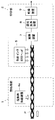
- FIG. 1 shows the configuration of a printing apparatus according to Embodiment 1 of the present invention.
- the printing apparatus includes a preprocessing unit 1 that performs preprocessing of the printing material P and a printing unit 2 that performs printing on the printing material P.
- the printed material P includes, for example, a polyester fiber ground structure having a high capillary force and in which ink is easily retained, and a polyester having a capillary force lower than this ground texture and in which ink is less likely to remain than the ground texture. It is comprised from the fastener snap (snap) which consists of.
- the capillary force indicates the ability to retain ink in each region of the printing material P, and the region having a high capillary force collects ink from the peripheral region having a relatively low capillary force by the capillary force.
- the region having a low capillary force cannot hold the ink by an attractive force from a peripheral region having a relatively strong capillary force.
- the pre-processing unit 1 includes a deactivator supply device 3 that supplies a deactivator to the printing material P, and a coagulant supply device 4 that supplies the coagulant to the printing material P.
- the deactivator is for deactivating the aggregating agent so as not to cause an aggregating reaction between the aggregating agent and the aggregate, and the aggregating agent and the aggregate are reacted and aggregated by contacting each other. As a result, the viscosity increases (gelation).
- the deactivator supply device 3 is arranged on the back surface side where there is no snap of the printing material P, and supplies the deactivating agent to the ground structure of the printing material P by, for example, an inkjet method.
- the flocculant supply device 4 is disposed on the surface side where the snap of the printing material P is present, and supplies the flocculant to the surface side of the printing material P.
- the flocculant supplied by the flocculant supply device 4 maintains the relationship that each droplet on the surface of the snap is sufficiently smaller than the capillary force length and the radius of curvature of the snap surface expressed by the above formula (2).
- the supply conditions for the flocculant supply density and size are selected. As a result, the flocculant stays at the supply position and can be prevented from moving to the ground structure of the substrate P to be printed.
- the flocculant is adjusted to a size of 10 ⁇ m or less, for example.
- an ultrasonic atomizer or an air spray that supplies the flocculant in a mist form of several ⁇ m to several tens ⁇ m can be used.
- printing can be performed at intervals so that the flocculant does not coalesce by inkjet.
- a printing unit 2 is disposed on the downstream side of the preprocessing unit 1 with respect to the moving direction of the printing material P.
- print heads 5 and 6, a heating device 7, a reduction cleaning device 8, and a drying device 9 are sequentially arranged in the moving direction of the printing material P.
- the print head 5 is disposed on the back side of the printing material P and ejects ink onto the ground structure by an ink jet method.
- the print head 6 is disposed on the surface side of the printing material P, and ejects ink containing aggregates onto the printing material P.
- a dye which is prepared as an ink jet ink together with an aggregate is used by using a disperse dye as a dyeing color material for dyeing polyester fibers or the like.
- the ink containing the aggregate to be fed supplied from the print head 6 to the snap is gelled by the aggregation reaction of the aggregate and the flocculant and is retained on the surface of the snap.
- the ink containing the aggregate to be fed supplied from the print head 6 to the ground structure is gelated without causing the aggregation target and the flocculant to agglutinate because the flocculant is previously deactivated by the deactivator. It penetrates into the local organization.
- the ink printed on the ground structure reaches the back surface by permeation, the front and back can be printed uniformly.
- a penetrating liquid composed of a dispersion liquid containing no coloring material.
- the heating device 7 heats the printed material P, and vaporizes (sublimates) the disperse dye in the ink that stays in the gel state in the snap together with the ink that has penetrated into the ground structure, and dyes the printed material P. is there.
- the reduction cleaning device 8 cleans the dyed printing material P.
- the drying device 9 is for drying and finishing the washed printing object P.
- the substrate P is moved in a certain direction by a moving device (not shown).
- the substrate P to be printed is obtained by attaching a snap 11 having a low capillary force to a ground tissue 10 having a high capillary force.
- the ground material 10 and the snap 11 are adjacent to each other in the printed material P, when ink is ejected onto the snap 11 as it is, the ink moves to the ground texture 10 due to the difference in capillary force. It is difficult to dye the snap 11 with a predetermined amount of ink.
- the deactivator supply device 3 deactivates the ground structure 10 from the back side of the substrate P. Supply.
- the supplied quencher penetrates to the surface side of the ground tissue 10, but does not reach the snap portion with a low capillary force.
- the flocculant supply device 4 adjusts the size and amount of the flocculant and supplies the flocculant, the flocculant supplied to the snap 11 does not coalesce with each other, and the ground structure 10 having a large capillary force. You can stay in the snap 11 without moving to.
- the printing material P moves to the printing unit 2 and ink is ejected from the print heads 5 and 6.
- ink ejected from the print head 5 is supplied to the ground structure 10 from the back surface side of the printing material P, it penetrates into the ground structure 10 as it is.
- the ink containing the aggregate to be ejected from the print head 6 is supplied to the snap 11 and the ground structure 10 from the surface side of the print object P.
- the ink containing the aggregate to be supplied to the snap 11 is gelled by the aggregation reaction between the aggregate and the flocculant present on the surface of the snap 11. In this way, the ink is retained on the surface of the snap 11 by becoming a gel.
- the quenching agent supplied to the ground structure 10 from the deactivator supply device 3 avoids the aggregation reaction between the aggregate and the flocculant in advance. For this reason, it does not gel and stay in the ground structure 10 but penetrates into the ground structure as it is.
- the predetermined amount of ink supplied to the snap 11 can be stopped without being moved to the ground structure 10.
- the printing material P is heated by the heating device 7 in a state where the ink is gelled and held on the snap 11.
- the ink supplied to the ground tissue 10 is vaporized by the heat treatment, and the pigment of the ink is dyed on the ground tissue.
- the ink that is supplied to the snap 11 and gelled is vaporized by the heat treatment, and the pigment of the ink is dyed into the snap 11.
- the printed material P on which the ink coloring matter is heat-fixed is washed by the reduction cleaning device 8 and dried by the drying device 9 to finish the dyeing of the printed material P.
- the snap 11 is made of polyester, after the dye is heated and fixed on the printing material P at 180 to 200 ° C. by the heating device 7, the printing material P is washed with heated alkaline water by the reduction cleaning device 8. Then, the printed material P can be dried and finished by the drying device 9.
- a predetermined amount of ink is simply gelled to a region having a low capillary force, and the printed material P having a region having a low capillary force can be easily set to a target color. Can be stained.
- the flocculant supply device 4 may supply the flocculant only to the snap 11 of the substrate P to be printed.
- the flocculant supply device 4 may be configured to have a cover 12 that covers the outer periphery of the snap 11 and supplies the mist-shaped flocculant only to the snap 11.
- the flocculant supply device 4 may adjust the direction in which the flocculant is supplied and supply the flocculant only to the snap 11.
- the print head 6 may be configured to supply the ink containing the aggregates only to the snaps 11 of the print target P. Thereby, even if it does not supply a deactivation agent to the ground structure 10 of the to-be-printed material P, the gelled ink can be fastened only to the snap 11.
- the deactivator supply device 3 may be used. It is not necessary to supply the deactivator to the ground structure 10 of the printing material P.
- the flocculant and the ink containing the aggregate are supplied from the front side of the printing material P, and the gel-like ink is fastened to the ground structure 10 and the snap 11. Thereafter, the heat treatment is performed by the heating device 7 and the gelled ink is vaporized, and the pigment of the ink is dyed on each of the ground structure 10 and the snap 11. Further, it is not necessary to supply ink from the print head 5 as long as the ground texture 10 of the substrate P can be dyed to a target color by the ink supplied from the print head 6.
- the deactivator supply device 3 may be disposed on the back side of the printing material P and between the flocculant supply device 4 and the print head 6.
- the deactivator is supplied to the ground structure 10 after the flocculant is supplied to the printing material P, and deactivates the flocculant. Further, the deactivator supply device 3 can be disposed on the surface side of the printing material P as long as the flocculant supplied to the ground texture 10 can be deactivated by the supplied deactivator.
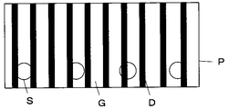
- continuous design printing D can be realized on a composite material having different printing characteristics including the snap portion S and the ground texture G.
- the flocculant supplied to the back surface, it is possible to prevent ink permeation when the back surface is printed by the print head 5, so that it is possible to realize design printing with different front and back sides.
- the ink droplet size sufficiently smaller than the thickness of the fabric, the ink can be aggregated before reaching the back surface by permeation. In this way, by controlling the presence or absence of the supply of the deactivator, it is possible to control the bleeding of the ink in the ground structure and the penetration into the back surface, thereby realizing different color development.
- Embodiment 2 As the printed material P used in the first embodiment, a plate-like resin material having different capillary force regions may be used. For example, as shown in FIG. 5, it is possible to use a printing material P in which a recess 21 is formed on a resin plate. When the concave portion 21 is formed on the resin plate, a difference in capillary force is generated between the convex portion 22 adjacent to the concave portion 21, and the ink supplied to the convex portion 22 easily moves to the adjacent concave portion 21. That is, the printing material P includes a concave portion 21 having a high capillary force and a convex portion 22 having a low capillary force.
- the edge portions on both sides of the bottom surface have a larger capillary force than the central portion of the concave portion, and ink droplets tend to collect at the edge portion.
- the flocculant is supplied from the flocculant supply device 4 to the printing material P. Since the flocculant is provided with a droplet size sufficiently smaller than the capillary force length, an ultrasonic atomizer or the like can be used.
- the ink containing the aggregate is supplied from the print head 6 to the concave portion 21 of the printed material P and the convex portion 22 adjacent thereto. In the convex portion 22, the aggregating agent and the aggregate to be contained in the ink undergo an agglutination reaction and gel.
- the ink is retained on the convex portion 22 by becoming a gel.
- the ink printed on the central portion of the concave portion 21 also stays at the printing position due to the aggregation reaction, and uniform printing can be realized without moving to the edge portion.
- the printed material P is heated by the heating device 7, and the ink remaining in the concave portions 21 and the convex portions 22 of the printed material P is vaporized and dyed.
- a printed material P in which regions having different wettability are formed on the resin plate and the region having high wettability has a low capillary force.
- a printed material P as shown in FIG. 6, a part of a resin plate is matted to reduce wettability, and has a matting region 23 having a high capillary force and a low capillary force. What consists of the surface 24 of a resin board can be used.
- the flocculant is supplied from the flocculant supply device 4 to the printing material P. Thereafter, the ink containing the aggregates is supplied from the print head 6 to the matted region 23 of the print target P and the surface 24 adjacent thereto.
- the aggregating agent and the aggregate to be contained in the ink undergo an agglutination reaction and gel.
- the ink is retained on the surface 24 by becoming a gel.
- the printing material P is heated by the heating device 7, and the ink remaining on the matting area 23 and the surface 22 of the printing material P is vaporized and dyed with a pigment.
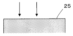
- the resin material having the wide surface 25 is easy to move the ink, and the ink moves and gathers in a part only by slightly different capillary force of the surface 25 of the resin material, and it is difficult to uniformly dye the entire surface 25.
- a flocculant and an ink containing an aggregate are supplied to the entire surface 25 of the printed material P to be gelled. Subsequently, the entire surface 25 of the printing material P can be uniformly dyed by heat-treating the printing material P in which the ink is gelled and fastened.
- a resin material composed of regions having different capillary forces can be easily dyed to a target color simply by gelling the ink.
- the ink ejected from the print heads 5 and 6 is one that is heat-treated by the heating device 7 and sublimated and transferred to the printing material P, but is not limited thereto.
- an ink that is contained in the ink by evaporation of the dispersion medium and in which the polymer component forms a film can be used.
- an ink for adhering the coloring material to the printing material P by including a component that is cured by energy irradiation such as heat or light to form a film.
- the film After supplying an ink using urethane acrylate or epoxy acrylate as a film forming component to the printing material P, the film is formed by subjecting the film forming component to radical polymerization by heat treatment and irradiation with energy such as ultraviolet rays. Color material can be adhered to P.
- the film After supplying ink using an epoxy resin prepolymer, urethane prepolymer, or the like as a film-forming component to the printed material P, the film is formed by reacting the film-forming component with heat treatment and coloring the printed material P. Can also be attached.
- an ink containing nano metal particles that become a film by heat treatment can be used. After supplying the ink to the printing material P, the nano metal particles contained in the ink are formed into a film on the printing material P by heat treatment, and a metal layer can be formed on the surface thereof.
- Embodiment 3 As shown in FIG. 8, a raised fabric made of a ground tissue having a high capillary force and a raised tissue having a low capillary force may be used as the printing material P used in the first embodiment.
- a deactivator is supplied to the ground structure from the back side of the printing material P by the deactivator supply device 3.
- the supplied quencher penetrates to the surface side of the ground tissue.
- a mist-like flocculant is supplied from the front side of the printing material P by the flocculant supply device 4.
- the flocculant supply device 4 adjusts the size and amount of the flocculant and supplies the flocculant, the flocculant supplied to the raised fabric is supplied at a size and interval at which the droplets do not coalesce.
- the print heads 5 and 6 eject ink onto the printing material P.
- the ink ejected from the print head 5 is supplied to the ground structure from the back side of the printing material P, the ink penetrates the ground structure as it is.
- the ink containing the aggregate to be ejected from the print head 6 is supplied to the surface side of the printed material P.
- the aggregate When ink containing an aggregate is supplied, the aggregate is gelled by an aggregating reaction with an aggregating agent present on the surface of the raised fabric. Thus, it becomes gel form, and ink is stopped by the raising part of a raising fabric.
- the quencher supplied to the ground texture from the deactivator supply device 3 avoids the agglomeration reaction between the two, so that the ink in the ground texture Does not stay gelled.
- the disperse dye used in the first embodiment is used as a color material, the printed matter P is heated by the heating device 7 as in the first embodiment, and the ink supplied to the ground structure is vaporized so that the pigment of the ink is formed.
- the ink that is dyed into the ground tissue and supplied to the raised fabric is gelled, and the pigment of the ink is dyed into the raised fabric.
- an acidic dye instead of a disperse dye as the color material, and dye nylon such as wool or wool as a printing material, or cotton as a printing material using a reactive dye.
- a steam process is desirable instead of the heat process.
- the side close to the tip of the raised portion is colored by the color material of the ink printed from the front side by the print head 6, and the side close to the ground structure is the color material from the back side by the print head 5. It can also be colored. It is possible to change the coloring degree of the front-end
- the printing apparatus of the present embodiment it is possible to easily dye a raised color composed of regions having different capillary forces into a target color simply by gelling the ink.
- Embodiment 4 As the printed material P used in Embodiment 1, a nonwoven fabric in which a large number of resin fibers such as polypropylene are randomly arranged in a planar shape may be used.
- the nonwoven fabric includes a region A in which the fiber density is arranged and a region B in which the fiber density is low, and the fiber density fluctuates.
- the region A having a high fiber density is more affected by the surface tension of the fiber than the region B having a low fiber density, so that the capillary force is increased.
- the ink droplets landed on the region B with low fiber density move to the region A with high fiber density.
- the droplets that have landed on the single fiber are not limited to the landing position, but move to a nearby fiber crossing position, that is, a position where the capillary force is higher than that of the single fiber.
- FIG. 13 shows the configuration of the printing apparatus according to the fourth embodiment.
- the printing apparatus according to the fourth embodiment is the same as the printing apparatus according to the first embodiment shown in FIG. 1 except that the flocculant supply apparatus 4 is provided on the surface side of the printing material P instead of the flocculant supply apparatus 4 and the deactivator.
- the supply device 3, the color material ink print head 6, the heating device 7 and the reduction cleaning device 8 are omitted.
- the flocculant is supplied onto the fibers of the printing material P from the flocculant supply device 4 a of the pretreatment unit 1.
- the aggregating agent for example, a cationic polymer is used.
- the printing material P is moved to the printing unit 2, and ink is ejected from the print head 5 onto the printing material P.
- the ink for example, an ink in which a pigment and an aqueous polymer are dispersed in an aqueous dispersion medium containing an anionic surfactant is used.
- the pigment and the aqueous polymer particles are dispersed in the aqueous dispersion medium in a stable state negatively charged by the anionic surfactant.
- an aqueous polymer for ink for example, a polymer containing polyolefin, polyurethane, acrylic, polyester, or the like can be used.
- the ink droplets that have landed on the area A of high fiber density or the area B of low fiber area of the printing medium P are cationic polymers in which aqueous polymer particles in the ink are present on the fibers of the printing medium P. And gels by agglutination reaction and remains in each region. In addition, a large amount of ink can remain on the printing surface of the printing material P.
- the ink aggregated on the fibers of the printing material P is dried by the drying device 9 to form a film of the aqueous polymer in the ink, and the colored polymer film incorporating the pigment is formed on the fibers of the printing material P. Formed.
- a print image can be formed on the printing material P only by the drying process by the drying device 9 without performing the cleaning process thereafter. it can.
- the printed material P is activated by corona treatment or plasma treatment before supplying the flocculant from the flocculant supply device 4a. It is desirable to keep it.
- Embodiment 5 As shown in FIG. 14, it is also possible to use, as the substrate to be printed P, a fiber bundle such as a woven fabric or a knitted fabric through which a region having a high capillary force passes from the front surface to the back surface.
- a yarn is constituted by a fiber bundle in which a plurality of polyester fibers, nylon fibers, cellulose fibers and the like having a diameter of 10 to 20 ⁇ m are gathered, and a woven fabric or a knitted fabric constituted by these yarns is used as the printing material P.
- a yarn composed of such a fiber bundle has a strong capillary force in a gap of several to several tens of microns between the fibers. For this reason, the ink droplets that have landed on the substrate to be printed penetrate and move along the fiber bundle and reach the back surface without staying. Therefore, as shown in FIG. 14, ink jet printing is performed only on a predetermined surface area F. It was difficult.
- fabrics and knitting used in the textile field, etc. require different functions on the inner side close to the skin (back surface area of the printed material) and the outer surface facing the outside (front surface area of the printed material). There is also.
- the inside needs to absorb moisture from sweat and to release heat by reacting with the moisture
- the outside is waterproof to prevent rain, etc., or the inside moisture appears as a stain.
- a water repellent function is required.
- the antistatic agent for preventing charging of the printed material and the water immersion treatment for increasing the moisture adsorption capacity of the fiber for each area.
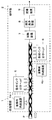
- FIG. 15 shows a configuration of a printing apparatus according to the fifth embodiment.
- the printing apparatus according to the fifth embodiment is the same as the printing apparatus according to the first embodiment shown in FIG. 1 except that the flocculant supply device 4a is provided on the surface side of the printing material P instead of the flocculant supply device 4, and the quenching agent.
- the supply device 3 and the color material ink print head 6 are omitted.
- the flocculant is supplied from the flocculant supply device 4a of the pretreatment unit 1 to the surface of the printing material P.
- the printing material P is moved to the printing unit 2, and ink containing a coagulant and a processing agent for converting the physical properties of the printing material P is applied to the surface of the printing material P from the color material ink print head 5. It is ejected by the inkjet method.
- the processing agent is adjusted so as to be supplied in an amount of 10 to 150% of the weight of the printed material, preferably several tens of percent of the weight of the printed material.
- some processing agents convert the physical properties of the printed material P and function as an aggregating agent. When a processing agent having the function of an aggregating agent is used, ink containing only the processing agent is ejected. can do.
- the ink droplets ejected from the print head 5 land on the substrate P and then penetrate into the fiber bundle in the surface area F of the printing surface, and the aggregating agent in the ink is supplied to the substrate P in advance.
- the speed of the agglutination reaction can be controlled by changing the concentration or the like of the aggregating agent or the aggregating agent, so that the ink containing the processing agent can be penetrated from the surface of the printing material P to an appropriate depth.
- the ink containing the processing agent can be attached to the predetermined surface region F by controlling the penetration of the ink containing the processing agent with respect to the position and depth of the printing material P.
- the printing material P is subjected to a heating process by the heating device 7, a cleaning process by the reduction cleaning device 8, and a drying process by the drying device 9.
- the surface area F of the substrate P can be dyed and a desired function can be imparted by the action of the processing agent.
- an antistatic agent obtained by adding a surfactant or the like to an aqueous polymer aqueous solution such as polyvinyl alcohol, aqueous polyester or aqueous acrylic is used.
- an aqueous dispersion of water repellent particles such as a fluororesin, a silicone resin, and a wax can be used.
- the water-repellent treatment agent is deposited on the substrate P and then formed into a film by drying and heat treatment, and if it contains a crosslinking agent, it adheres firmly to the fiber surface by a crosslinking reaction and exhibits a water-repellent function over a long period of time. I can do it.
- an aggregating function can be imparted by adding aqueous polyester, aqueous acrylic or the like as the aggregating agent.
- the flocculant supply device 4a supplies the flocculant toward the surface of the printing material P and the ink is applied from the print head 5.
- the present invention is not limited to this.
- the flocculant may be supplied to the back surface of the printed material P and ink containing the flocculant and the processing agent may be ejected.
- the concentration or the like of the flocculant or the aggregating agent by changing the concentration or the like of the flocculant or the aggregating agent, the permeation area of the ink penetrating from the back surface of the printed material P to the surface is controlled, and the predetermined back surface area of the printed material P is dyed. A desired function can be imparted.
- coagulant supply devices 4 a and 4 b are provided on the front side and the back side of the printing material P, respectively, and print heads 5 and 6 are provided on the front side and the back side of the printing material P, respectively.
- ink containing the aggregating agent and the processing agent can be ejected onto the front and back surfaces of the printing material P, respectively.
- the front surface area and the back surface area of the printing material P can be dyed with different color materials and can have different functions.
- the flocculant supply device 4 a and the print head 5 are provided on the front side of the printing material P with respect to the traveling direction of the printing material P, and the rear surface of the printing material P is provided behind it.
- the flocculant supply device 4b and the print head 6 can also be provided on the side.
- the flocculant supply device 4b and the print head 6 are provided on the back surface side of the printing material P with respect to the traveling direction of the printing material P, and the flocculant supply device 4a is provided behind and on the front surface side of the printing material P.
- the print head 5 may be provided.
- a dispersion containing an anionic surfactant is used as a dispersion in which an aggregate is dispersed (aggregate dispersion), and an acid is used as the coagulant.
- Aggregation reaction can be performed.
- the anionic surfactant is dispersed in a state adjusted to be neutral or alkaline.
- an organic acid is added as an aggregating agent and becomes acidic, the degree of dissociation is reduced and aggregation occurs.
- the aqueous polymer contained in the flocculant aggregates and gels.
- fatty acid sodium, monoalkyl sulfate, alkyl polyoxyethylene sulfate, alkylbenzene sulfonate, monoalkyl phosphate, etc. can be used as anionic surfactants, and malonic acid, citric acid, acetic acid can be used as acids.
- Inorganic acids such as organic acids such as dilute hydrochloric acid can be used.
- an alkali agent such as sodium carbonate, sodium hydrogen carbonate, or caustic soda that suppresses acidification by an organic acid can be used.
- the agglomeration reaction may be performed by a reaction using an aggregate dispersion liquid dispersion-stabilized with an anionic surfactant and an organic cationic polymer, or an aggregate dispersion liquid dispersion-stabilized with a cationic surfactant.
- a reaction by a flocculant composed of an organic anionic polymer can be used.
- an anionic surfactant is negatively charged and dispersed, but when an organic cationic polymer is added as an aggregating agent, the charge is neutralized and aggregated to be gelled.
- a compound having an amino group (-NH2) such as ammonia or alkylamine and a compound having a guanidino group or biguanide group such as arginine, guanidine, or biguanide derivative having more nitrogen can be used.
- a polymer having an amino group or imino group in the side chain or main chain an aqueous polymer containing a synthetic polymer such as polyethyleneimine, polyvinylamine or polyallylamine, and a polyamino acid such as polyornithine or polylysine can be used.
- the stabilized anionic surfactant used as an aggregate a polyacrylamide partially hydrolyzed or a copolymer of acrylamide and sodium acrylate can be used as the stabilized anionic surfactant used as an aggregate.
- an inorganic aggregate and a cationic polymer aggregate Can be used. Accordingly, the water-soluble polymer contained in the aggregate is aggregated and gelled. Further, coagulation may be used for the aggregation reaction.
- neutralizing agents such as electrolytes or alcohols
- the flocculant When added, it becomes electrically neutral, and the repulsion between the colloidal particles disappears to cause aggregation. Along with this, the colloidal particles are aggregated and gelled.
- hydrophobic colloid and a hydrocolloid an aluminum salt (aluminum sulfate, polyaluminum chloride) or an iron salt (polyferric sulfate, ferric chloride) is used.
- the agglomerates contain a hydrophobic colloid or a hydrocolloid dispersed in an agglomerate dispersion, and can also undergo an agglutination reaction by using a hydrophobic colloid or a hydrophilic colloid neutralizer as an aggregating agent.
- the viscosity of the ink may be increased by utilizing a crosslinking reaction by an aggregating agent composed of an aggregate dispersion containing a crosslinkable polymer (monomer or oligomer) and a crosslinking initiator.
- a crosslinking reaction with a polyvinyl alcohol (PVA) resin solution and boric acid a urethane resin-based reaction that causes a chemical reaction by mixing a polyol having a hydroxyl group at a terminal and a urethane prepolymer having an isocyanate group at a terminal and a polyol, or
- An epoxy resin-based reaction that causes a reaction with a curing agent such as an amine to the epoxy resin prepolymer can be used.
- the agglomerate can be subjected to an agglutination reaction by using a cross-linkable polymer dispersed in an agglomerate dispersion and using a cross-linking initiator of a cross-linkable polymer as an aggregating agent.
- a flocculant that can provide the flocculant with a size equal to or less than the capillary force length and the radius of curvature of the printing material can be selected.
- the droplets after landing by a device capable of generating fine droplets, such as an ultrasonic atomizer and air spray, are sized so as to remain at the landing position including the united droplets as shown in FIG. Adjust and supply.
- a supply method in which the droplet size and position are controlled as shown in FIG. 9B by an ink jet method, a gravure roller coating method, or the like can also be employed.
- the flocculant and the agglomerated material can be realized so that the landing of the ink including the agglomerated material can be realized while the flocculant is held at the landing position.
- an ink jet apparatus that prints ink containing ink almost simultaneously. As shown in FIG. 10, by using an ink jet device 31 in which a flocculant and a color material ink print head are arranged close to each other or integrated, the landing position and time are made to coincide with each other, which is shorter than the droplet moving time. It can be gelled in time. The ink containing the aggregating agent or the aggregate can stay at the landing position without moving from the landing position to the region of high capillary force.
- Embodiment 6 As shown in FIG. 11, the printing unit used in the printing apparatus according to the first to fifth embodiments prints each area of the printing material P based on the input data and prints the results printed on the printing material P. It is possible to achieve a configuration that corrects by feedback and realizes a desired color.
- the printing unit 41 of the present embodiment includes a supply condition calculation unit 42, a printing characteristic database (DB) 43, a control unit 44, a print driving unit 45, and print heads 46 to 48.
- the supply condition calculation unit 42 includes information on the printed material P including a plurality of regions (for example, a ground tissue region and a raised tissue region) having different color development characteristics and a printed image to be printed on the printed material P.
- Information on the reproduction target color is input as input data by the operator.
- the information on the printing material P includes information such as the material / thickness, the presence / absence of the aggregate and the aggregating agent, and the type / amount of the aggregate and the aggregating agent for each area of the printing material.
- the information about the reproduction target color includes information on the chromaticity of the reproduction target color in each area of the substrate P, each pixel, color blur (spatial frequency), front / back uniformity, and the like.
- the supply condition calculation unit 42 is connected to the print characteristic DB 43.
- the supply condition calculation unit 42 searches the print characteristic DB 43 based on the information on the printing object P and the information on the reproduction target color, and print heads 46 to 46 showing the color development closest to the reproduction target color for each area of the printing object P.
- ink types, ink supply parameters, penetrant supply parameters, and pretreatment section conditions (deactivator, flocculant) are extracted.
- the supply parameters of the ink and the penetrating liquid include the voltage, frequency, waveform, and the like output to the print heads 46-48.
- the print characteristic DB 43 includes the relationship between the print amount of each color ink and the color development characteristics after completion of the color development process for each region. At this time, the relationship between color development characteristics (spatial frequency characteristics of printed image, uniformity of front and back colors) according to the presence / absence of addition of the aggregate and the aggregating agent or the amount of the aggregate and the aggregating agent is included.
- the “penetrating liquid” is a liquid for promoting permeation for appropriately penetrating the ink after printing into the printing material, and is preferably a dispersion medium constituting the ink. By printing “penetrating liquid”, the ink can reach the back surface of the printing object even when printing a small amount.
- the supply condition calculation unit 42 is connected to the control unit 44.
- the control unit 44 inputs an electric signal indicating the ink type, ink supply parameter, and permeating liquid supply parameter required for each region extracted by the supply condition calculation unit 42 to the print driving unit 45, so that the print object P is printed. Controls printing.
- the control unit 44 is connected to the print driving unit 45.
- the print drive unit 45 drives the print heads 46 to 48 in accordance with the electrical signal input from the control unit 44.
- the print drive unit 45 is connected to the print heads 46 to 48.
- the print heads 46 to 48 are so-called ink jet type print heads, which eject four types of ink Y, M, C, K or penetrating liquid.
- the print head 46 ejects ink from the front side of the substrate P, and the print head 47 ejects ink from the back side of the substrate P.
- the print head 48 ejects the penetrating liquid from the front side of the printing material P.
- the print head 47 ejects ink containing an aggregate to be printed P.
- a heating device 49, a reduction cleaning device 50, and a drying device 51 are arranged on the downstream side of the print heads 46 to 48 with respect to the moving direction of the printing material P, and the coloring material in the ink is fixed to the printing material P.
- a convex region measuring device 52 and a ground texture measuring device 53 are arranged downstream of the drying device 51 with respect to the traveling direction of the substrate P, and the convex region printing result measurement value input unit 54 is provided in the convex region measuring device 52.
- the convex area printing result measurement value input unit 54 and the ground texture printing result measurement value input unit 55 are connected to the supply condition calculation unit 42.
- the convex region measuring device 52 and the ground texture measuring device 53 are for measuring the optical characteristics from the convex region such as the raised portion of the printing material P and the ground texture, respectively, and measuring the color development amount.
- the convex region print result measurement value input unit 54 and the ground texture print result measurement value input unit 55 input the measurement values obtained in the convex region measurement device 52 and the ground texture measurement device 53 to the supply condition calculation unit 42.
- the printing result of the substrate P is fed back.
- the supply condition calculation unit 42 prints the supply condition values of the ink to be ejected and the penetrating liquid in which the measurement value input from the print result measurement value input unit 54 is corrected so as to realize the same color as the reproduction target color. This is obtained for each region of the object P.
- the supply condition calculation unit 42 searches the print characteristic DB 43 based on the information on the printing material P input by the operator and the information on the reproduction target color of the print image to be printed on the printing material P.
- the supply condition calculation unit 42 indicates a type similar to each region (for example, each region of the raised tissue to which the ground texture and the flocculant are added) on the printed material P from the printed material region type information in the printing characteristic DB 43. Search for each.
- the supply condition calculation unit 42 uses the data of the print characteristic DB 43 to predict color development when supplying supply parameters for all ink types of the print heads 46 and 47 and the penetrant liquid of the print head 48, and provides color development information. It is also possible to calculate and combine the supply parameters so that the coloring information becomes the coloring information target by an optimization method. Specifically, using the following formulas (3) and (4), K / S is used to obtain the relationship between the printing amount and the color development information, and the linear programming method by the simplex method, the successive approximation method, the genetic method, etc. Optimization techniques can be used. In addition, the supply condition calculation unit 42 can obtain a plurality of combinations of supply parameters close to the color reproduction target in the print characteristic DB 43 and obtain an optimum supply parameter by interpolation.
- K / S (1-Rc) 2 / 2Rc (3)
- (K / S) mix Jy (K / S) y + Jm (K / S) m + Jc (K / S) c + Jk (K / S) k (4)
- Formula (3) shows the relationship among the absorption intensity K by a color material, the light scattering intensity S from a to-be-printed object, and the reflectance Rc in each wavelength.
- (K / S) mix indicates K / S of a region where a plurality of color materials are printed and mixed
- (K / S) y, (K / S) m, (K / S) c and (K / S) k respectively indicate K / S when unit amounts of the four color materials are adhered
- Jy, Jm, Jc and Jk respectively indicate the four color materials on the printed material. Indicates the amount of adhesion.
- the ink type, ink supply parameter, and permeate supply parameter for each area of the printing material P extracted by the supply condition calculation unit 42 in this way are output to the control unit 44.
- the control unit 44 outputs the supply parameters of the ink and the penetrating liquid to the print drive unit 45
- the print drive unit 45 sends a drive signal corresponding to these supply parameters to the print heads 46 to 48 corresponding to the ink type or the penetrating liquid.
- the ink and the penetrating liquid are ejected onto each area of the printing material P.
- the target color can be reproduced with respect to each area even for a print object in which areas such as a ground structure having a high capillary force, a fastener element portion having a low capillary force, and a raised portion are combined.
- the coloring can be performed, and the uniformity in the thickness direction of the printing material P and the spatial frequency characteristics can be achieved as desired.
- ink and penetrating ink droplets are repeatedly applied to all regions with the ink and penetrant supply parameters extracted for each region of the substrate P.
- the printed object P that has been printed is heated by the heating device 49, then reduced and cleaned by the reduction cleaning device 50, and dried by the drying device 51.
- the dried printing material P is color-measured by the convex area measuring device 52 and the ground texture measuring apparatus 53, and the measured value is passed through the convex area printing result measured value input section 54 and the ground texture printing result measured value input section 55. Input to the supply condition calculation unit 42.
- the supply condition calculation unit 42 When the input measurement value is outside the allowable range of chromaticity of the reproduction target color, the supply condition calculation unit 42 performs measurement input from the convex region printing result measurement value input unit 54 and the ground texture printing result measurement value input unit 55. Ink and penetrant supply parameters to be ejected from the respective head portions of the print heads 46 to 48 are corrected so that the values match the chromaticity of the reproduction target color. The ink and penetrant supply parameters corrected by the supply condition calculation unit 42 are output to the control unit 44, and the control unit 44 uses the print driving unit 45 to set the print heads 46 to 48 on the basis of these supply parameters. The drive is controlled, and printing is performed on the substrate P.
- the correction does not fall within the allowable range of the chromaticity of the target color to be reproduced, it is preferable to repeat the above correction until it falls within the allowable range. If the input measurement values for the front / back uniformity and the spatial frequency are outside the allowable level of the target value, the supply condition of the preprocessing unit can be corrected to match the target value.
- the supply condition calculation unit 42 accumulates the supply parameter corrected by the feedback of the printing result in the print characteristic DB 43 every time it is corrected, or the supply already stored in the print characteristic DB 43 by the corrected supply parameter.
- a learning function can be provided by updating the parameters. As described above, the accuracy of information stored in the print characteristic DB 43 can be improved by learning each time printing is repeated.
- 1 Pretreatment section, 2, 41 printing section, 3 deactivator supply device, 4, 4a, 4b flocculant supply device, 5, 6, 46 to 48 print head, 7, 49 heating device, 8, 50 reduction cleaning device 9, 51 Drying device, 10 Ground texture, 11 Snap, 12 Cover, 21 Concave portion, 22 Convex portion, 23 Matting region, 24, 25 Surface, 31 Inkjet device, 42 Supply condition calculation unit, 43 Printing characteristic database, 44 Control unit, 45 printing drive unit, 52 convex area measuring device, 53 ground texture measuring device, 54 convex area printing result measured value input part, 55 ground texture printing result measured value input part, P printing object, G ground texture, S Snap part, D design printing.
Landscapes
- Engineering & Computer Science (AREA)
- Textile Engineering (AREA)
- Chemical & Material Sciences (AREA)
- Materials Engineering (AREA)
- Chemical Kinetics & Catalysis (AREA)
- Toxicology (AREA)
- Health & Medical Sciences (AREA)
- General Health & Medical Sciences (AREA)
- Physics & Mathematics (AREA)
- Wood Science & Technology (AREA)
- Thermal Sciences (AREA)
- Life Sciences & Earth Sciences (AREA)
- Electromagnetism (AREA)
- Organic Chemistry (AREA)
- Coloring (AREA)
- Ink Jet Recording Methods And Recording Media Thereof (AREA)
- Coating Apparatus (AREA)
- Ink Jet (AREA)
- Application Of Or Painting With Fluid Materials (AREA)
Abstract
La présente invention concerne un procédé d'impression et un dispositif d'impression permettant de colorer avec des couleurs ciblées la totalité d'imprimés comprenant une pluralité de zones présentant entre elles des forces de capillarité différentes. Un dispositif d'alimentation en agent coagulant (4) apporte, au moins à la zone de l'imprimé présentant une faible force de capillarité, un agent coagulant qui favorise la réaction de coagulation de l'agrégat coagulé qui à été gélifié par coagulation. En direction au moins de la zone de l'imprimé présentant une faible force de capillarité, une tête d'impression (6) éjecte par jet d'encre des gouttelettes d'encre contenant l'agrégat coagulé. L'encre gélifiée par la réaction de coagulation entre l'agrégat coagulé et l'agent coagulant est fixée sur l'imprimé par un dispositif chauffant (7).
Priority Applications (2)
| Application Number | Priority Date | Filing Date | Title |
|---|---|---|---|
| EP11826632.9A EP2620543B1 (fr) | 2010-09-24 | 2011-07-13 | Procédé d'impression et dispositif d'impression |
| US13/770,621 US20130155162A1 (en) | 2010-09-24 | 2013-02-19 | Printing method and printing device |
Applications Claiming Priority (4)
| Application Number | Priority Date | Filing Date | Title |
|---|---|---|---|
| JP2010213594 | 2010-09-24 | ||
| JP2010-213594 | 2010-09-24 | ||
| JP2011116975A JP5893850B2 (ja) | 2010-09-24 | 2011-05-25 | 印字方法および印字装置 |
| JP2011-116975 | 2011-05-25 |
Related Child Applications (1)
| Application Number | Title | Priority Date | Filing Date |
|---|---|---|---|
| US13/770,621 Continuation US20130155162A1 (en) | 2010-09-24 | 2013-02-19 | Printing method and printing device |
Publications (1)
| Publication Number | Publication Date |
|---|---|
| WO2012039186A1 true WO2012039186A1 (fr) | 2012-03-29 |
Family
ID=45873681
Family Applications (1)
| Application Number | Title | Priority Date | Filing Date |
|---|---|---|---|
| PCT/JP2011/066000 WO2012039186A1 (fr) | 2010-09-24 | 2011-07-13 | Procédé d'impression et dispositif d'impression |
Country Status (4)
| Country | Link |
|---|---|
| US (1) | US20130155162A1 (fr) |
| EP (1) | EP2620543B1 (fr) |
| JP (1) | JP5893850B2 (fr) |
| WO (1) | WO2012039186A1 (fr) |
Cited By (2)
| Publication number | Priority date | Publication date | Assignee | Title |
|---|---|---|---|---|
| TWI617713B (zh) * | 2016-07-06 | 2018-03-11 | 總成實業股份有限公司 | 編織物的染整方法及其具有預定顏色的布料、鞋面布料 |
| JP2019039095A (ja) * | 2017-08-24 | 2019-03-14 | 京セラドキュメントソリューションズ株式会社 | インクジェット捺染装置 |
Families Citing this family (15)
| Publication number | Priority date | Publication date | Assignee | Title |
|---|---|---|---|---|
| US11447648B2 (en) | 2004-05-30 | 2022-09-20 | Kornit Digital Ltd. | Process and system for printing images on absorptive surfaces |
| CN102656237B (zh) | 2009-08-10 | 2014-07-09 | 柯尼特数码有限公司 | 用于可拉伸基材的喷墨组合物及方法 |
| JP5708921B2 (ja) * | 2011-03-22 | 2015-04-30 | セイコーエプソン株式会社 | インクジェット捺染装置及び捺染物の製造方法 |
| JP5928679B2 (ja) * | 2011-07-14 | 2016-06-01 | セイコーエプソン株式会社 | インクジェット捺染装置及び捺染物の製造方法 |
| JP5840564B2 (ja) * | 2012-05-16 | 2016-01-06 | 富士フイルム株式会社 | 印字方法および印字装置 |
| JP6404491B2 (ja) | 2015-04-20 | 2018-10-10 | コーニンクレッカ フィリップス エヌ ヴェKoninklijke Philips N.V. | 試料上のカバー層の印刷を制御する印刷制御デバイス |
| EP3482945B1 (fr) * | 2016-07-11 | 2022-04-06 | FUJIFILM Corporation | Dispositif et procédé de traitement d'image, programme, et système d'impression à jet d'encre |
| JP6703457B2 (ja) * | 2016-08-05 | 2020-06-03 | 株式会社ミマキエンジニアリング | 印刷済媒体製造方法および印刷済媒体製造装置 |
| EP3532548B1 (fr) * | 2016-10-31 | 2024-04-24 | Kornit Digital Ltd. | Impression par jet d'encre par sublimation de colorant pour textile |
| WO2019077615A1 (fr) | 2017-10-22 | 2019-04-25 | Kornit Digital Ltd. | Images à faible coefficient de frottement par impression à jet d'encre |
| DE102017127062B4 (de) * | 2017-11-17 | 2019-08-14 | Océ Holding B.V. | Verfahren und Beschichtungseinheit zum Aufbringen eines Beschichtungsstoffes auf einen Aufzeichnungsträger |
| JP7068620B2 (ja) * | 2017-11-28 | 2022-05-17 | 株式会社ノーリツ | 温水ユニット用の外装ケース、温水ユニットおよび温水ユニット用の外装ケースの製造方法 |
| JP2019162777A (ja) * | 2018-03-19 | 2019-09-26 | 株式会社リコー | 液体吐出装置、液体吐出方法およびプログラム |
| GB201905021D0 (en) * | 2019-04-09 | 2019-05-22 | Alchemie Tech Ltd | Improvements in or relating to industrial textile dyeing |
| US11413896B2 (en) | 2020-11-18 | 2022-08-16 | International Imaging Materials, Inc. | Digital textile printing inks having zero volatile organic compound solvents therein |
Citations (10)
| Publication number | Priority date | Publication date | Assignee | Title |
|---|---|---|---|---|
| JPS5719084A (en) | 1980-07-09 | 1982-02-01 | Asahi Chem Ind Co Ltd | Disposal of waste water |
| JPS60238193A (ja) | 1984-05-11 | 1985-11-27 | Kurita Water Ind Ltd | 含油廃水の処理方法 |
| JPH01125326A (ja) | 1987-11-09 | 1989-05-17 | Shigemi Kiyono | 細菌性表皮疾患治療薬 |
| JPH0369631A (ja) | 1989-08-03 | 1991-03-26 | Seiren Co Ltd | 有毛布帛着色物とその製法 |
| JPH0879782A (ja) | 1994-08-31 | 1996-03-22 | Nippon Denki Syst Kensetsu Kk | パソコン用動画像処理装置 |
| JPH0946869A (ja) | 1995-08-02 | 1997-02-14 | Iwabuchi Kk | 電柱用バンドの締付け器 |
| JP2003049375A (ja) * | 2001-08-07 | 2003-02-21 | Seiza Sangyo Kk | 捺染模様を有する凹凸構造布帛の製造方法 |
| JP2005206974A (ja) * | 2004-01-23 | 2005-08-04 | Canon Electronics Inc | 布帛用前処理装置および該布帛用前処理装置を用いて布地処理が施された布帛 |
| JP2006015725A (ja) * | 2004-05-31 | 2006-01-19 | Fuji Xerox Co Ltd | インクジェット記録方法及びインクジェット記録装置 |
| JP2008062389A (ja) * | 2006-09-04 | 2008-03-21 | Fuji Xerox Co Ltd | 液滴吐出装置 |
Family Cites Families (14)
| Publication number | Priority date | Publication date | Assignee | Title |
|---|---|---|---|---|
| EP1125760B1 (fr) * | 1999-07-30 | 2006-05-17 | Seiko Epson Corporation | Procede d'enregistrement comprenant des supports d'enregistrement et d'impression avec deux composes liquides |
| JP2002103783A (ja) * | 2000-09-28 | 2002-04-09 | Ricoh Co Ltd | インクジェット記録用インクセット及び記録方法 |
| JP2003247179A (ja) * | 2002-02-26 | 2003-09-05 | Upepo & Maji Inc | インクジェット方式での捺染方法 |
| JP2003326828A (ja) * | 2002-05-16 | 2003-11-19 | Seiko Epson Corp | 前処理液の吐出検査方法並びに検査液塗布具及び検査シート |
| JP2006206686A (ja) * | 2005-01-26 | 2006-08-10 | Fuji Xerox Co Ltd | インク、インクセット、記録方法、インクタンク、並びに記録装置 |
| JP2006206687A (ja) * | 2005-01-26 | 2006-08-10 | Fuji Xerox Co Ltd | インク、インクセット、記録方法、インクタンク、並びに記録装置 |
| EP1851063B1 (fr) * | 2005-02-17 | 2014-04-30 | Tritron GmbH | Pretraitement et/ou pre-enduction de substrats non absorbants et/ou de supports non absorbants |
| JP2006326983A (ja) * | 2005-05-25 | 2006-12-07 | Fujifilm Holdings Corp | インクジェット記録装置及び方法 |
| JP2007169528A (ja) * | 2005-12-22 | 2007-07-05 | Fuji Xerox Co Ltd | インク、インクセット、記録方法、インクカートリッジ、及び記録装置 |
| US9149750B2 (en) * | 2006-09-29 | 2015-10-06 | Mott Corporation | Sinter bonded porous metallic coatings |
| JP2008231617A (ja) * | 2007-03-20 | 2008-10-02 | Canon Inc | インクジェット捺染方法及び捺染物 |
| EP2078786A3 (fr) * | 2008-01-10 | 2011-01-05 | Diehlmann, Gernot, Dr. | Procédé d'impression sur des matériaux absorbants non blancs |
| US8220913B2 (en) * | 2008-08-28 | 2012-07-17 | Fujifilm Corporation | Ink-jet recording method |
| WO2010100972A1 (fr) * | 2009-03-05 | 2010-09-10 | コニカミノルタIj株式会社 | Procédé d'enregistrement/impression textile à jet d'encre |
-
2011
- 2011-05-25 JP JP2011116975A patent/JP5893850B2/ja active Active
- 2011-07-13 EP EP11826632.9A patent/EP2620543B1/fr not_active Not-in-force
- 2011-07-13 WO PCT/JP2011/066000 patent/WO2012039186A1/fr active Application Filing
-
2013
- 2013-02-19 US US13/770,621 patent/US20130155162A1/en not_active Abandoned
Patent Citations (10)
| Publication number | Priority date | Publication date | Assignee | Title |
|---|---|---|---|---|
| JPS5719084A (en) | 1980-07-09 | 1982-02-01 | Asahi Chem Ind Co Ltd | Disposal of waste water |
| JPS60238193A (ja) | 1984-05-11 | 1985-11-27 | Kurita Water Ind Ltd | 含油廃水の処理方法 |
| JPH01125326A (ja) | 1987-11-09 | 1989-05-17 | Shigemi Kiyono | 細菌性表皮疾患治療薬 |
| JPH0369631A (ja) | 1989-08-03 | 1991-03-26 | Seiren Co Ltd | 有毛布帛着色物とその製法 |
| JPH0879782A (ja) | 1994-08-31 | 1996-03-22 | Nippon Denki Syst Kensetsu Kk | パソコン用動画像処理装置 |
| JPH0946869A (ja) | 1995-08-02 | 1997-02-14 | Iwabuchi Kk | 電柱用バンドの締付け器 |
| JP2003049375A (ja) * | 2001-08-07 | 2003-02-21 | Seiza Sangyo Kk | 捺染模様を有する凹凸構造布帛の製造方法 |
| JP2005206974A (ja) * | 2004-01-23 | 2005-08-04 | Canon Electronics Inc | 布帛用前処理装置および該布帛用前処理装置を用いて布地処理が施された布帛 |
| JP2006015725A (ja) * | 2004-05-31 | 2006-01-19 | Fuji Xerox Co Ltd | インクジェット記録方法及びインクジェット記録装置 |
| JP2008062389A (ja) * | 2006-09-04 | 2008-03-21 | Fuji Xerox Co Ltd | 液滴吐出装置 |
Non-Patent Citations (1)
| Title |
|---|
| See also references of EP2620543A4 |
Cited By (2)
| Publication number | Priority date | Publication date | Assignee | Title |
|---|---|---|---|---|
| TWI617713B (zh) * | 2016-07-06 | 2018-03-11 | 總成實業股份有限公司 | 編織物的染整方法及其具有預定顏色的布料、鞋面布料 |
| JP2019039095A (ja) * | 2017-08-24 | 2019-03-14 | 京セラドキュメントソリューションズ株式会社 | インクジェット捺染装置 |
Also Published As
| Publication number | Publication date |
|---|---|
| EP2620543A4 (fr) | 2014-05-07 |
| EP2620543A1 (fr) | 2013-07-31 |
| EP2620543B1 (fr) | 2016-09-07 |
| JP2012086549A (ja) | 2012-05-10 |
| US20130155162A1 (en) | 2013-06-20 |
| JP5893850B2 (ja) | 2016-03-23 |
Similar Documents
| Publication | Publication Date | Title |
|---|---|---|
| JP5893850B2 (ja) | 印字方法および印字装置 | |
| US11898048B2 (en) | Inkjet compositions and processes for stretchable substrates | |
| US9616683B2 (en) | Formaldehyde-free inkjet compositions and processes | |
| JP6517218B2 (ja) | 捺染方法及び捺染装置 | |
| US11566143B2 (en) | Image forming method and ink set | |
| EP2284232A1 (fr) | Composition pour finissage par jet d'encre en continu d'un article textile | |
| ES2587080T3 (es) | Composición para el acabado por inyección de tinta bajo demanda de un artículo textil | |
| JP5840217B2 (ja) | 印字方法および印字装置 | |
| JP5917253B2 (ja) | 印字装置および印字方法 | |
| JP5914157B2 (ja) | 印字方法および印字装置 | |
| WO2012005103A1 (fr) | Procédé d'impression, dispositif d'impression et nappe à force capillaire | |
| JP3410026B2 (ja) | インクジェット捺染用皮革及びその製造方法 | |
| JP5840564B2 (ja) | 印字方法および印字装置 | |
| CN103009859B (zh) | 图像记录用组合物、其制法、图像记录装置和图像记录方法 | |
| JP2002348786A (ja) | インクジェット捺染用布帛の製造方法、インクジェット捺染用布帛、インクジェット捺染方法、およびインクジェット捺染物 | |
| WO2021126258A1 (fr) | Support de tissu imprimable | |
| JP2011212939A (ja) | インクジェット画像形成方法。 | |
| KR20060040928A (ko) | 고내광성 실사출력용 잉크젯 날염 원단의 코팅조성물 및 출력용직물 |
Legal Events
| Date | Code | Title | Description |
|---|---|---|---|
| 121 | Ep: the epo has been informed by wipo that ep was designated in this application |
Ref document number: 11826632 Country of ref document: EP Kind code of ref document: A1 |
|
| REEP | Request for entry into the european phase |
Ref document number: 2011826632 Country of ref document: EP |
|
| WWE | Wipo information: entry into national phase |
Ref document number: 2011826632 Country of ref document: EP |
|
| NENP | Non-entry into the national phase |
Ref country code: DE |