WO2012033105A1 - レーザ装置 - Google Patents
レーザ装置 Download PDFInfo
- Publication number
- WO2012033105A1 WO2012033105A1 PCT/JP2011/070294 JP2011070294W WO2012033105A1 WO 2012033105 A1 WO2012033105 A1 WO 2012033105A1 JP 2011070294 W JP2011070294 W JP 2011070294W WO 2012033105 A1 WO2012033105 A1 WO 2012033105A1
- Authority
- WO
- WIPO (PCT)
- Prior art keywords
- laser
- light
- phase
- laser beams
- continuous
- Prior art date
Links
Images


Classifications
-
- G—PHYSICS
- G02—OPTICS
- G02F—OPTICAL DEVICES OR ARRANGEMENTS FOR THE CONTROL OF LIGHT BY MODIFICATION OF THE OPTICAL PROPERTIES OF THE MEDIA OF THE ELEMENTS INVOLVED THEREIN; NON-LINEAR OPTICS; FREQUENCY-CHANGING OF LIGHT; OPTICAL LOGIC ELEMENTS; OPTICAL ANALOGUE/DIGITAL CONVERTERS
- G02F1/00—Devices or arrangements for the control of the intensity, colour, phase, polarisation or direction of light arriving from an independent light source, e.g. switching, gating or modulating; Non-linear optics
- G02F1/01—Devices or arrangements for the control of the intensity, colour, phase, polarisation or direction of light arriving from an independent light source, e.g. switching, gating or modulating; Non-linear optics for the control of the intensity, phase, polarisation or colour
-
- H—ELECTRICITY
- H01—ELECTRIC ELEMENTS
- H01S—DEVICES USING THE PROCESS OF LIGHT AMPLIFICATION BY STIMULATED EMISSION OF RADIATION [LASER] TO AMPLIFY OR GENERATE LIGHT; DEVICES USING STIMULATED EMISSION OF ELECTROMAGNETIC RADIATION IN WAVE RANGES OTHER THAN OPTICAL
- H01S3/00—Lasers, i.e. devices using stimulated emission of electromagnetic radiation in the infrared, visible or ultraviolet wave range
- H01S3/10—Controlling the intensity, frequency, phase, polarisation or direction of the emitted radiation, e.g. switching, gating, modulating or demodulating
- H01S3/13—Stabilisation of laser output parameters, e.g. frequency or amplitude
- H01S3/1307—Stabilisation of the phase
-
- H—ELECTRICITY
- H01—ELECTRIC ELEMENTS
- H01S—DEVICES USING THE PROCESS OF LIGHT AMPLIFICATION BY STIMULATED EMISSION OF RADIATION [LASER] TO AMPLIFY OR GENERATE LIGHT; DEVICES USING STIMULATED EMISSION OF ELECTROMAGNETIC RADIATION IN WAVE RANGES OTHER THAN OPTICAL
- H01S3/00—Lasers, i.e. devices using stimulated emission of electromagnetic radiation in the infrared, visible or ultraviolet wave range
- H01S3/23—Arrangements of two or more lasers not provided for in groups H01S3/02 - H01S3/22, e.g. tandem arrangements of separate active media
- H01S3/2308—Amplifier arrangements, e.g. MOPA
-
- H—ELECTRICITY
- H01—ELECTRIC ELEMENTS
- H01S—DEVICES USING THE PROCESS OF LIGHT AMPLIFICATION BY STIMULATED EMISSION OF RADIATION [LASER] TO AMPLIFY OR GENERATE LIGHT; DEVICES USING STIMULATED EMISSION OF ELECTROMAGNETIC RADIATION IN WAVE RANGES OTHER THAN OPTICAL
- H01S5/00—Semiconductor lasers
- H01S5/06—Arrangements for controlling the laser output parameters, e.g. by operating on the active medium
- H01S5/068—Stabilisation of laser output parameters
- H01S5/06821—Stabilising other output parameters than intensity or frequency, e.g. phase, polarisation or far-fields
-
- H—ELECTRICITY
- H01—ELECTRIC ELEMENTS
- H01S—DEVICES USING THE PROCESS OF LIGHT AMPLIFICATION BY STIMULATED EMISSION OF RADIATION [LASER] TO AMPLIFY OR GENERATE LIGHT; DEVICES USING STIMULATED EMISSION OF ELECTROMAGNETIC RADIATION IN WAVE RANGES OTHER THAN OPTICAL
- H01S5/00—Semiconductor lasers
- H01S5/10—Construction or shape of the optical resonator, e.g. extended or external cavity, coupled cavities, bent-guide, varying width, thickness or composition of the active region
- H01S5/12—Construction or shape of the optical resonator, e.g. extended or external cavity, coupled cavities, bent-guide, varying width, thickness or composition of the active region the resonator having a periodic structure, e.g. in distributed feedback [DFB] lasers
-
- H—ELECTRICITY
- H01—ELECTRIC ELEMENTS
- H01S—DEVICES USING THE PROCESS OF LIGHT AMPLIFICATION BY STIMULATED EMISSION OF RADIATION [LASER] TO AMPLIFY OR GENERATE LIGHT; DEVICES USING STIMULATED EMISSION OF ELECTROMAGNETIC RADIATION IN WAVE RANGES OTHER THAN OPTICAL
- H01S5/00—Semiconductor lasers
- H01S5/40—Arrangement of two or more semiconductor lasers, not provided for in groups H01S5/02 - H01S5/30
- H01S5/4012—Beam combining, e.g. by the use of fibres, gratings, polarisers, prisms
-
- H—ELECTRICITY
- H01—ELECTRIC ELEMENTS
- H01S—DEVICES USING THE PROCESS OF LIGHT AMPLIFICATION BY STIMULATED EMISSION OF RADIATION [LASER] TO AMPLIFY OR GENERATE LIGHT; DEVICES USING STIMULATED EMISSION OF ELECTROMAGNETIC RADIATION IN WAVE RANGES OTHER THAN OPTICAL
- H01S5/00—Semiconductor lasers
- H01S5/40—Arrangement of two or more semiconductor lasers, not provided for in groups H01S5/02 - H01S5/30
- H01S5/4025—Array arrangements, e.g. constituted by discrete laser diodes or laser bar
- H01S5/4087—Array arrangements, e.g. constituted by discrete laser diodes or laser bar emitting more than one wavelength
-
- G—PHYSICS
- G02—OPTICS
- G02F—OPTICAL DEVICES OR ARRANGEMENTS FOR THE CONTROL OF LIGHT BY MODIFICATION OF THE OPTICAL PROPERTIES OF THE MEDIA OF THE ELEMENTS INVOLVED THEREIN; NON-LINEAR OPTICS; FREQUENCY-CHANGING OF LIGHT; OPTICAL LOGIC ELEMENTS; OPTICAL ANALOGUE/DIGITAL CONVERTERS
- G02F2203/00—Function characteristic
- G02F2203/56—Frequency comb synthesizer
-
- H—ELECTRICITY
- H01—ELECTRIC ELEMENTS
- H01S—DEVICES USING THE PROCESS OF LIGHT AMPLIFICATION BY STIMULATED EMISSION OF RADIATION [LASER] TO AMPLIFY OR GENERATE LIGHT; DEVICES USING STIMULATED EMISSION OF ELECTROMAGNETIC RADIATION IN WAVE RANGES OTHER THAN OPTICAL
- H01S2301/00—Functional characteristics
- H01S2301/08—Generation of pulses with special temporal shape or frequency spectrum
-
- H—ELECTRICITY
- H01—ELECTRIC ELEMENTS
- H01S—DEVICES USING THE PROCESS OF LIGHT AMPLIFICATION BY STIMULATED EMISSION OF RADIATION [LASER] TO AMPLIFY OR GENERATE LIGHT; DEVICES USING STIMULATED EMISSION OF ELECTROMAGNETIC RADIATION IN WAVE RANGES OTHER THAN OPTICAL
- H01S3/00—Lasers, i.e. devices using stimulated emission of electromagnetic radiation in the infrared, visible or ultraviolet wave range
- H01S3/005—Optical devices external to the laser cavity, specially adapted for lasers, e.g. for homogenisation of the beam or for manipulating laser pulses, e.g. pulse shaping
- H01S3/0064—Anti-reflection devices, e.g. optical isolaters
-
- H—ELECTRICITY
- H01—ELECTRIC ELEMENTS
- H01S—DEVICES USING THE PROCESS OF LIGHT AMPLIFICATION BY STIMULATED EMISSION OF RADIATION [LASER] TO AMPLIFY OR GENERATE LIGHT; DEVICES USING STIMULATED EMISSION OF ELECTROMAGNETIC RADIATION IN WAVE RANGES OTHER THAN OPTICAL
- H01S3/00—Lasers, i.e. devices using stimulated emission of electromagnetic radiation in the infrared, visible or ultraviolet wave range
- H01S3/05—Construction or shape of optical resonators; Accommodation of active medium therein; Shape of active medium
- H01S3/06—Construction or shape of active medium
- H01S3/0602—Crystal lasers or glass lasers
- H01S3/0606—Crystal lasers or glass lasers with polygonal cross-section, e.g. slab, prism
-
- H—ELECTRICITY
- H01—ELECTRIC ELEMENTS
- H01S—DEVICES USING THE PROCESS OF LIGHT AMPLIFICATION BY STIMULATED EMISSION OF RADIATION [LASER] TO AMPLIFY OR GENERATE LIGHT; DEVICES USING STIMULATED EMISSION OF ELECTROMAGNETIC RADIATION IN WAVE RANGES OTHER THAN OPTICAL
- H01S3/00—Lasers, i.e. devices using stimulated emission of electromagnetic radiation in the infrared, visible or ultraviolet wave range
- H01S3/05—Construction or shape of optical resonators; Accommodation of active medium therein; Shape of active medium
- H01S3/06—Construction or shape of active medium
- H01S3/063—Waveguide lasers, i.e. whereby the dimensions of the waveguide are of the order of the light wavelength
- H01S3/067—Fibre lasers
- H01S3/06754—Fibre amplifiers
-
- H—ELECTRICITY
- H01—ELECTRIC ELEMENTS
- H01S—DEVICES USING THE PROCESS OF LIGHT AMPLIFICATION BY STIMULATED EMISSION OF RADIATION [LASER] TO AMPLIFY OR GENERATE LIGHT; DEVICES USING STIMULATED EMISSION OF ELECTROMAGNETIC RADIATION IN WAVE RANGES OTHER THAN OPTICAL
- H01S3/00—Lasers, i.e. devices using stimulated emission of electromagnetic radiation in the infrared, visible or ultraviolet wave range
- H01S3/10—Controlling the intensity, frequency, phase, polarisation or direction of the emitted radiation, e.g. switching, gating, modulating or demodulating
- H01S3/11—Mode locking; Q-switching; Other giant-pulse techniques, e.g. cavity dumping
- H01S3/1106—Mode locking
-
- H—ELECTRICITY
- H01—ELECTRIC ELEMENTS
- H01S—DEVICES USING THE PROCESS OF LIGHT AMPLIFICATION BY STIMULATED EMISSION OF RADIATION [LASER] TO AMPLIFY OR GENERATE LIGHT; DEVICES USING STIMULATED EMISSION OF ELECTROMAGNETIC RADIATION IN WAVE RANGES OTHER THAN OPTICAL
- H01S3/00—Lasers, i.e. devices using stimulated emission of electromagnetic radiation in the infrared, visible or ultraviolet wave range
- H01S3/23—Arrangements of two or more lasers not provided for in groups H01S3/02 - H01S3/22, e.g. tandem arrangements of separate active media
- H01S3/2383—Parallel arrangements
- H01S3/2391—Parallel arrangements emitting at different wavelengths
-
- H—ELECTRICITY
- H01—ELECTRIC ELEMENTS
- H01S—DEVICES USING THE PROCESS OF LIGHT AMPLIFICATION BY STIMULATED EMISSION OF RADIATION [LASER] TO AMPLIFY OR GENERATE LIGHT; DEVICES USING STIMULATED EMISSION OF ELECTROMAGNETIC RADIATION IN WAVE RANGES OTHER THAN OPTICAL
- H01S5/00—Semiconductor lasers
- H01S5/005—Optical components external to the laser cavity, specially adapted therefor, e.g. for homogenisation or merging of the beams or for manipulating laser pulses, e.g. pulse shaping
Definitions
- the present invention relates to a laser device that generates pulsed laser light.
- a mode-locked laser device described in Patent Document 1 is known as a laser device in the above technical field.
- a mode-locked laser device described in Patent Document 1 is a method in which laser light modulated at a frequency that is an integral multiple of a resonator longitudinal mode interval is a plurality of amplifiers (optical fibers) having gains in spectral regions having different center frequencies, that is, center wavelengths. By amplifying with an amplifier or the like, pulse laser light in a plurality of wavelength regions is generated at a time.
- pulsed laser light has a higher peak light intensity than continuous light having the same energy per unit time, that is, average power. For this reason, when amplifying pulsed laser light, it is necessary to increase the pulse width to reduce the peak light intensity or limit the amplification factor for the purpose of preventing damage to the amplifier. For this reason, in a laser device that amplifies pulse laser light, it is difficult to generate high-power pulse laser light.
- the present invention has been made in view of such circumstances, and a laser device capable of easily generating a short-pulse and high-power pulse laser beam and a high-power pulse laser beam. It is an object of the present invention to provide a laser device capable of performing the above.
- the laser device includes a plurality of oscillating means that oscillate each of a plurality of laser lights having different frequencies and continuous light, and a laser beam oscillated from each of the oscillating means is combined at a predetermined position.
- the optical system includes: multiplexing means for generating combined light; and phase control means for controlling each phase of the laser light so that a peak of the output of the combined light repeatedly appears at a predetermined time interval at a predetermined position.
- this laser apparatus when a plurality of laser beams having different frequencies are combined at a predetermined position to generate a combined light, an output peak of the combined light repeatedly appears at a predetermined time interval at the predetermined position. In addition, the phase of each laser beam is controlled. Thereby, pulsed laser light is generated at a predetermined position.
- each of a plurality of laser beams is combined to generate a pulsed laser beam. For this reason, by increasing the number of oscillation means (that is, the number of laser beams having different frequencies), it is possible to easily generate short-pulse and high-power pulse laser beams.
- each of the oscillation means can oscillate each of the laser beams having different frequencies with a substantially constant frequency difference.
- the frequency difference between the laser beams oscillated from the oscillation means is substantially constant, it is easy to control each phase of the laser beams so that the output peak of the combined beam repeatedly appears at a predetermined time interval. It becomes. Therefore, it is possible to generate a pulsed laser beam having a short pulse and a high output more easily.
- the oscillation means can be a semiconductor laser. In this case, it is possible to reduce the size and weight of the laser device and to reduce power consumption. In addition, the mechanical stability of the laser device can be improved. Furthermore, the manufacturing cost of the laser device can be reduced.
- each of the oscillation means is connected to an optical fiber through which each of the laser light propagates, and the phase control means controls each phase of the laser light by controlling each temperature of the optical fiber. be able to. In this case, each phase of the laser light can be easily controlled by controlling the temperature of the optical fiber.
- This laser apparatus includes an oscillating unit that oscillates a laser pulse train composed of a plurality of continuous laser beams having different frequencies, and a component that divides the laser pulse train oscillated from the oscillating unit into a plurality of continuous laser beams having different frequencies.
- a multiplexing means for amplifying each of the continuous laser light amplified by the wave means, the continuous laser light demultiplexed by the demultiplexing means, and the continuous laser light amplified by the amplification means at a predetermined position.
- a phase control means for controlling each phase of the continuous laser light so that the peak of the output of the combined light repeatedly appears at a predetermined time interval at a predetermined position.
- each of a plurality of continuous laser beams is amplified by the amplification means. For this reason, an amplification factor can be set high compared with the case where a pulsed laser beam is amplified. Further, when each of the amplified continuous laser beams is combined at a predetermined position to generate a combined light, the output peak of the combined light repeatedly appears at a predetermined time interval at the predetermined position. In this way, the phase of each continuous laser beam is controlled. Thereby, a pulsed laser beam is generated at a predetermined position by the plurality of amplified continuous laser beams. Therefore, according to this laser device, it is possible to generate high-power pulsed laser light.
- the oscillating means can oscillate a laser pulse train composed of continuous laser beams having mutually different frequencies with a substantially constant frequency difference.
- the phases of the continuous laser beams having different frequencies it becomes easy to cause the output peak of the combined light to appear repeatedly at predetermined time intervals. Therefore, high-power pulsed laser light can be easily generated.
- it may further comprise a frequency difference adjusting means for adjusting a frequency difference between continuous laser beams constituting the laser pulse train oscillated from the oscillating means.
- the pulse repetition rate of the generated pulse laser beam can be adjusted by adjusting the frequency difference between the continuous laser beams.
- the oscillation means can be a mode-locked oscillator or a high-speed current modulation semiconductor laser. In this case, it is possible to reduce the size and weight of the laser device and to reduce power consumption. In addition, the mechanical stability of the laser device can be improved. Furthermore, the manufacturing cost of the laser device can be reduced.
- the amplifying means is a fiber array including a plurality of optical fibers that propagate and amplify each of the continuous laser beams demultiplexed by the demultiplexing means, or a slab type solid-state laser amplifier.
- the phase of each continuous laser beam can be controlled based on the result of the measurement. In this case, for example, by providing a spectral phase modulator in front of the demultiplexing means, it is possible to easily control the phases of the continuous laser beams having different frequencies.
- generate a high output pulse laser beam can be provided. .
- FIG. 1 is a configuration diagram of a laser apparatus according to a first embodiment of the present invention. It is a block diagram of the phase control apparatus shown by FIG.
- FIG. 4 is a partially enlarged view showing a heater of the phase control unit shown in FIG. 3. It is a graph which shows the output time waveform of the combined light shown by FIG.
- FIG. 6 is a configuration diagram of a modification of the laser device shown in FIG. 2. It is a graph for demonstrating an optical frequency comb.
- FIG. 9 is a partial cross-sectional view illustrating a configuration of the channel amplifier illustrated in FIG. 8. It is a figure for demonstrating operation
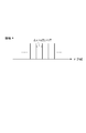
- the laser apparatus generates pulsed laser light equivalent to laser light oscillated from a mode-locked laser that realizes an optical frequency comb. Therefore, the optical frequency comb and mode-locked oscillation will be described.
- a Fabry-Perot resonator there are a plurality of longitudinal mode laser beams.
- a state in which the frequencies of the laser beams are arranged at equal intervals in this way is called an optical frequency comb.
- a laser light source equipped with such a resonator if phase modulation is not performed on each laser beam, the phase relationship between the laser beams is random, so that the output light of the laser light source that is the combined light is output.
- the time waveform is also random.
- the output time waveform of the output light is repeated by performing phase modulation of each laser light so that the phases of the laser lights are aligned using a saturable absorption element or an optical modulator.
- the laser device 1 oscillates each of a plurality of laser beams L 1 which are continuous light and have different frequencies with a certain frequency difference like the optical frequency comb described above.
- a plurality (three in this case) of laser light sources (oscillating means) 10 are provided.
- Each of the laser light sources 10 can be, for example, a distributed feedback semiconductor laser (DFB semiconductor laser) whose oscillation wavelengths are different from each other by 0.1 nm.
- continuous light is laser light whose output is substantially constant with respect to time, and pulsed laser light is such that its output peak repeatedly appears at predetermined time intervals. Laser light.
- the laser device 1 is connected to each of the laser light sources 10, and an optical fiber 11 through which each of the laser light L 1 oscillated from the laser light source 10 propagates, and an optical path of the laser light L 1 emitted from the optical fiber 11.
- a lens disposed between (multiplexing means) 12, each of the laser beam L 1 having passed through the lens 12 is further provided with a diffraction grating (multiplexing means) 13 for entering.
- the lens 12 is disposed at a position away from the emission end of the optical fiber 11 by the focal length.
- the diffraction grating 13 is disposed at a position separated from the lens 12 by the focal length of the lens 12. Therefore, each of the laser beams L 1 emitted from the optical fiber 11 passes through the lens 12 to become a parallel beam, and is focused on the focusing position P 1 of the diffraction grating 13.
- the diffraction grating 13 combines the laser beam L 1 at the condensing position P 1 to generate a combined beam L 2 .
- the laser device 1 further includes a phase control device (phase control means) 20.
- the phase controller 20 causes the output peak of the combined light L 2 to repeatedly appear at a predetermined time interval at the condensing position P 1 of the diffraction grating 13 (so that the same pulse time waveform repeatedly appears at a predetermined time interval). ) controls the phase of each of the laser light L 1. This phase control will be specifically described.
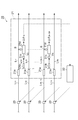
- the phase control device 20 includes a phase difference detection unit 21, a signal control unit 22, and a phase control unit 23.
- the phase difference detection unit 21 utilizes laser heterodyne interferometry, and laser beams having frequencies adjacent to each other on the frequency axis of the laser beams L 1 emitted from the laser light source 10 (hereinafter simply referred to as “adjacent”).
- the phase difference between L 1 ) (referred to as “matching laser light”) is detected, and information indicating the detection result is transmitted to the signal control unit 22.
- the phase difference detection unit 21 splits the laser beams L 11 and L 12 adjacent to each other in the laser beam L 1 by the optical coupler 21a, and then splits the split laser beams. It couple
- the laser beam L 11 uses the angular frequency ⁇ 1 and the phase ⁇ 1
- the laser beam L 12 is expressed by using the angular frequency ⁇ 2 and the phase ⁇ 2 , It is expressed.
- the above E 2 (t) is It can be expressed as. Therefore, the electrical signal V 2 (t) generated by the photodetector 21c is As such, a beat signal having an angular frequency difference ⁇ omega and the phase difference ⁇ theta 12. Then, by taking the exclusive OR of the clock signal S having the electric signal V 2 (t) and the angular frequency ⁇ omega by the phase meter 21d, the phase difference between the laser light L 11 and the laser beam L 12 ⁇ ⁇ 12 Can be requested.
- the laser beam L 1N is Therefore , the electric signal V N (t) generated from the adjacent laser beam L 1 (N ⁇ 1) and the laser beam L 1N is It becomes.
- N represents the Nth laser beam L1N .
- the phase difference ⁇ (N ⁇ 1) N between the laser beam L 1 (N ⁇ 1) and the laser beam L 1N is obtained. Can be requested.
- the signal controller 22 Based on the information indicating the phase difference between the adjacent laser beams L 1 obtained as described above, the signal controller 22 makes each laser beam L 1 such that the phases of the laser beams L 1 are the same.
- the phase control amount is obtained, and information indicating the obtained control amount is transmitted to each of the phase control units 23.
- Each of the phase control units 23 controls the respective phases of the laser light L 1 based on the information indicating the control amount transmitted from the signal control unit 22.
- the phase control unit 23 is provided in each of the optical fibers 11.
- the phase control unit 23 includes a bobbin BB in which a heater H is incorporated.
- each of the optical fibers 11 is wound around the bobbin BB.
- the phase control part 23 has the plate member PL in which the heater H was installed, as FIG.4 (b) shows, for example.
- each of the optical fibers 11 is disposed between the plate member PL and the heater H.
- Each phase control unit 23 controls the amount of heat generated by each heater H based on the information indicating the control amount transmitted from the signal control unit 22, adjusts the temperature of each optical fiber 11, and sets each optical fiber 11. adjusting the optical path length of the laser beam L 1 propagating.
- the temperature coefficient of the optical path length is 28.8 ⁇ m / (mK) (see (Opt. Laser Technol. 37, 29-32 (2004)). ) temperature When 1.064 ⁇ m a predetermined center wavelength of the laser beam L 1 factor is 27 ⁇ / (mK). Therefore, by appropriately selecting the length of the temperature adjusting portion of the optical fiber 11 and the temperature adjustment amount, the optical path length can be adjusted to about ⁇ / 100.
- the phase control device 20 controls the phase of the laser light L 1 , so that the combined light L 2 generated by the diffraction grating 13 is generated by the mode-frequency oscillation of the optical frequency comb as shown in FIG. It becomes a pulse laser beam equivalent to the laser beam.
- the combined light L 2 generated by the diffraction grating 13 is condensed at a predetermined position by the lens 14.
- the laser light L 1 that is continuous light is oscillated from each of the laser light sources 10.
- Each of the laser beams L 1 oscillated from the laser light source 10 propagates through each of the optical fibers 11.
- the phases of the laser beams L 1 propagating through the optical fibers 11 are made identical to each other at the multiplexing position P 1 by the phase controller 20.
- Each of the laser lights L 1 having the same phase is emitted from the optical fiber 11 and then condensed on the diffraction grating 13 by passing through the lens 12.
- each of the laser beams L 1 collected on the diffraction grating 13 are combined with each other by the diffraction grating 13 and output from the laser device 1 after passing through the lens 14 as combined light L 2 that is pulsed laser light. Is done.
- combined light L 2 is a parallel beam, it is possible to adjust the focal length of the lens 12, the groove density of the grating 13, and the incident angle to the diffraction grating 13.
- the laser apparatus 1 when the laser light L 1 is combined to generate the combined light L 2 , the combined light L at the condensing position P 1 of the diffraction grating 13. as the peak of the second output appears repeatedly at a predetermined time interval, and controls the phase of each of the laser light L 1.
- pulsed laser light in the light converging position P 1 is generated.
- this laser device 1 generates a pulsed laser beam by combining a plurality of laser beams L 1. Therefore, by increasing the number of laser light sources 10 (i.e., the number of the laser beam L 1 of different frequencies), the pulsed laser beam of short pulse and high output can be easily generated.
- the laser device 1 is converted by multiplexing the respective laser beams L 1 is a continuous light in the laser pulse train. Therefore, non-linear optical effects (for example, self-phase modulation, beam breakup, etc.) and narrow band (increase in pulse width) when amplifying pulsed laser light do not occur. Therefore, according to the laser apparatus 1, compared with the laser apparatus which amplifies pulsed laser light, it is possible to generate pulsed laser light that has high beam quality, high repetition, and short pulses.
- the laser in the apparatus 1 since the frequency difference between the laser light L 1 is emitted from the laser light source 10 is constant, the multiplexed light L laser beam L 1 as peak appears repeatedly at a predetermined time interval of the output of the 2 It is easy to control the respective phases. Therefore, it is possible to generate a pulsed laser beam having a short pulse and a high output more easily.
- each of the laser light sources 10 is a semiconductor laser
- the laser apparatus can be reduced in size and weight, and the power consumption can be reduced.
- the mechanical stability of the laser device can be improved.
- the manufacturing cost of the laser device can be reduced.
- the phase control unit 20 by controlling the respective temperatures of the optical fiber 11, and controls the phase of each of the laser light L 1, easily respective phase of the laser beam L 1 Can be controlled.
- the laser device 1 is configured to generate the combined light L 2 by combining the laser beams L 1 with the diffraction grating 13.
- FIG. 6 a configuration may be adopted in which the combined light L 2 is generated by combining the laser light L 1 at the focal position P 2 of the lens 12 without using the diffraction grating 13.
- the laser light source 10 may be a DFB semiconductor laser array in which DFB semiconductor lasers are arranged one-dimensionally, or a fiber laser array using a fiber Bragg diffraction grating.
- the laser light source 10 and DFB semiconductor laser array by laminating the DFB semiconductor laser array, arranging the oscillation source of the laser beam L 1 in two dimensions, facilitating the number of laser beam L 1 Therefore, the laser device 1 can be downsized.
- the laser device 1 may include an amplifier that amplifies each of the laser beams L 1 oscillated from each of the laser light sources 10. That is, in the laser device 1, the respective optical fibers 11 may be replaced with an optical fiber amplifier for amplifying with each propagation of the laser beam L 1. In that case, the phase control device 20 controls the respective phases of the laser light L 1 by controlling the temperatures of the optical fibers in the optical fiber amplifier.
- the laser apparatus uses a mode-locked laser that realizes an optical frequency comb as a laser light source. Therefore, the optical frequency comb and mode-locked oscillation will be described.
- a laser light source equipped with such a resonator if phase modulation is not performed on each laser beam, the phase relationship between the laser beams is random, so that the output light of the laser light source that is the combined light is output.
- the time waveform is also random.
- Such an oscillating means may be a light source in which short pulses repeatedly appear at predetermined time intervals, such as a high-frequency current-modulated semiconductor laser.
- the laser apparatus 1A includes a laser light source (oscillating means) 10A such as a mode-locked laser that realizes the optical frequency comb as described above or a semiconductor laser with high repetition current modulation.
- the seed light LA 0 that is the output light of the laser light source 10A is pulsed light (laser pulse train), and is composed of a plurality of continuous laser lights having different frequencies and having the same phase with a certain frequency difference. That is, the laser light source 10A combines a plurality of laser beams that are continuous light and have different frequencies with a certain frequency difference, and oscillates as seed light LA 0 that is pulsed laser light.
- continuous light continuous laser light
- pulsed laser light is laser light whose output is substantially constant with respect to time, and pulsed laser light has its output peak repeated at predetermined time intervals. It is a laser beam that appears.
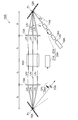
- the laser device 1A further includes an optical isolator 11A and a diffraction grating (branching means) 12A that are sequentially arranged on the optical path of the seed light LA 0 oscillated from the laser light source 10A.
- the optical isolator 11A prevents return light to the laser light source 10A.
- Diffraction grating 12A is laser light LA 1 demultiplexes a plurality (three in this case) the seed light LA 0 for each frequency (i.e., a plurality of continuous laser frequency of the laser pulse train emitted from the laser light source 10A mutually different Demultiplexing to light LA 1 ).
- the diffraction grating 12A causes the angular dispersion of the optical frequency comb in seed light LA 0. Further in other words, the diffraction grating 12A is spatially arranged in each frequency a plurality of laser light contained in the seed light LA 0. At this time, each of the laser beams LA 1 is spatially arranged in order of frequency.
- the laser device 1A further includes a lens 13A disposed on the optical path of the laser beam LA 1 demultiplexed by the diffraction grating 12A.
- Lens 13A is the focal length is f 1, is disposed at a position away from the incident position P 0 of the seed light LA 0 distance f 1 in the diffraction grating 12A. Therefore, each of the laser beams LA 1 demultiplexed by the diffraction grating 12A passes through the lens 13A, travels in parallel with each other at a predetermined interval ⁇ x, and collects at a position f 1 from the lens 13A. Lighted.
- the laser beam LA 1 the wavelength spacing ⁇ lambda of adjacent
- the laser beam LA 1 together spacing ⁇ x adjacent
- the focal length f 1 of the lens 13A is 1 m
- the number of grooves N is 1200 g / mm
- the incident angle ⁇ of the seed light LA 0 with respect to the diffraction grating 12A is 20 deg
- the diffraction angle is 1060 nm. 68.43 deg.
- the spacing ⁇ x when the wavelength spacing ⁇ is 0.375 pm, 37.5 pm, and 0.375 nm is 1.22 ⁇ m, 122 ⁇ m, and 1.22 mm, respectively.
- the laser device 1A further includes a channel amplifier (amplifying means) 14A disposed on the optical path of the laser light LA 1 that has passed through the lens 13A.
- Channel amplifier 14A is incident to each of the laser beams LA 1 passing through the lens 13A, it amplifies the respective laser beam LA 1 incident for emitting a laser light LA 2.
- the channel amplifier 14A is a fiber array configured by arranging a plurality of optical fibers 14aA to which an active medium (for example, Nd, Yb, Er, Bi, Pr, etc.) is added in an array. It is. Therefore, the channel amplifier 14A amplifies while propagating respective laser beam LA 1.
- an active medium for example, Nd, Yb, Er, Bi, Pr, etc.
- Channel amplifier 14A has its light incident end face 14bA are arranged such that the position away from the lens 13A by the distance f 1. Accordingly, each of the laser beams LA 1 demultiplexed by the diffraction grating 12A passes through the lens 13A and is collected on the light incident end face 14bA of the channel amplifier 14A. Since the interval ⁇ x between the adjacent laser beams LA 1 is obtained as described above, by setting the interval between adjacent cores of the optical fiber 14aA constituting the channel amplifier 14A as ⁇ x, one optical fiber 14aA. It is possible to propagate the laser beam LA 1 having one frequency.
- the laser device 1A is disposed on the optical path of laser beam LA 2 emitted from the channel amplifier 14A sequentially lens (multiplexing means) 15A and the diffraction grating (multiplexing means) 16A to further I have.
- Lens 15A is the focal length is f 2
- the diffraction grating 16A is disposed at a position away from the lens 15A by a distance f 2.
- the laser beam LA 2 emitted from the channel amplifier 14A is combined in the light converging position P 1 of the diffraction grating 16A, the multiplexed light LA 3 as an output light of the laser device 1A is generated.
- the groove density of the focal length f 2 and the diffraction grating 16A of the lens 15A by a groove density different from the value of the focal length f 1 and the diffraction grating 12A of the lens 13A, is of the multiplexed light LA 3 parallel beams
- the beam thickness can be set to a desired value.
- the laser device 1A further includes a phase control device (phase control means) 20A.
- Phase control unit 20A in the light converging position P 1 of the diffraction grating 16A, so that the peak of the output of the multiplexed light LA 3 appear repeatedly at predetermined time intervals (such that the same pulse time waveform appears repeatedly at a predetermined time interval ) Control each phase of the laser beam LA 1 . This phase control will be specifically described.
- the phase control device 20A includes a spectral phase measuring device (FROG et al., J. Paye et al., Opt. Lett. 18, 1946-1948 (1993)) 21A and a spectral phase modulator (for example, a diffraction grating and a liquid crystal spatial modulator). Or an acoustooptic programmable dispersion filter, P. Tournois et al., Opt. Commun. 140, 245-249 (1997)) 22A.
- FROG et al. J. Paye et al., Opt. Lett. 18, 1946-1948 (1993)
- a spectral phase modulator for example, a diffraction grating and a liquid crystal spatial modulator.
- an acoustooptic programmable dispersion filter P. Tournois et al., Opt. Commun. 140, 245-249 (1997)
- the laser device 1A, a half mirror 23A for branching a part of multiplexed light LA 3, the multiplexed light LA 3 which is branched by the half mirror 23A and the mirror 24A for guiding the spectral phase meter 21A Is provided.
- phase control device 20A the respective phases of the laser light LA 1 are controlled as follows. That is, in the phase controlling apparatus 20A, a portion of the combined light LA 3 is input to the spectral phase meter 21A by the half mirror 23A and the mirror 24A. Spectral phase meter 21A measures the input multiplexed light LA 3 of spectral phase (phase varied between positions P 1 from the position P 0). More specifically, the spectrum phase measuring device 21A measures each phase of the laser light LA 2 included in the input combined light LA 3 . Then, the spectrum phase measuring device 21A transmits (feeds back) information indicating the measurement result to the spectrum phase modulator 22A.
- Spectral phase modulator 22A is the spectrum based on the information indicating the measurement result from the phase measuring device 21A, the multiplexed light peak output of LA 3 as appears repeatedly at a predetermined time interval (same pulse time waveform of a predetermined time).
- the phase of each of the laser beams LA 1 included in the seed beam LA 0 is controlled so as to appear repeatedly at intervals. That is, the phase control device 20A measures the spectral phase of the combined light LA 3 and controls the phase of the laser light LA 1 based on the measurement result (and thus controls the phase of the laser light LA 2 ). ).
- the phase control device 20A controls the phases of a plurality of laser beams having different frequencies constituting the seed light LA 0 (corrects the phase change added between the position P 0 and the position P 1 for each frequency).
- the combined light LA 3 generated by the diffraction grating 16A becomes a pulsed laser light having an increased peak intensity equivalent to the laser light of the optical frequency comb that has been mode-locked.
- the seed light LA 0 from the laser light source 10A is oscillated.
- the seed light LA 0 oscillated from the laser light source 10A passes through the spectral phase modulator 22A and the optical isolator 11A and reaches the diffraction grating 12A.
- the seed light LA 0 reaching the diffraction grating 12A is demultiplexed into a plurality of laser beams LA 1 for each frequency by the diffraction grating 12A.
- Each phase of the laser beam LA 1 demultiplexed by the diffraction grating 12A is controlled by the spectral phase modulator 22A so that the combined beam LA 3 generated later becomes a pulsed laser beam.
- Each diffraction grating 12A of the demultiplexed laser light LA enters the channel amplifier 14A.
- Each of the laser beams LA 2 emitted from the channel amplifier 14A passes through the lens 15A and is condensed on the diffraction grating 16A.
- the laser beams LA 2 collected on the diffraction grating 16A are combined with each other by the diffraction grating 16A and output from the laser device 1A as combined light LA 3 that is pulsed laser light.
- Some of the multiplexed light L 3, which is output at this time is input to the spectral phase meter 21A, is subjected to measurement of spectral phase.
- the laser apparatus 1A to amplify each of the plurality of continuous light of the laser beam LA 1 in the channel amplifier 14A. For this reason, an amplification factor can be set high compared with the case where a pulsed laser beam is amplified.
- the peak of the output power of the combined light LA 3 in the light converging position P 1 is at a predetermined time interval
- Each phase of the laser beam LA 1 is controlled so that it appears repeatedly.
- a pulse laser beam is generated by the plurality of amplified laser beams LA 2 at the condensing position P 1 . Therefore, according to this laser device, it is possible to generate high-power pulsed laser light.
- the seed light LA 0 that is a laser pulse train is demultiplexed into laser light LA 1 that is continuous light by the diffraction grating 12A, and each laser light LA 1 is continuously amplified by the channel amplifier 14A. It is converted again into a laser pulse train by the diffraction grating 16A.
- the laser device 1A since the laser device 1A performs continuous optical amplification in the channel amplifier 14A, nonlinear optical effects (for example, self-phase modulation, beam breakup, etc.) and a narrow band (pulse width) when the pulse laser light is amplified. Increase) does not occur. Therefore, according to the laser apparatus 1A, it is possible to generate pulse laser light having high beam quality, high repetition, and short pulses as compared with a laser apparatus that amplifies pulse laser light.
- each peak of the output power of the combined light LA 3 is the laser beam LA 1 to appear repeatedly at predetermined time intervals It is easy to control the phase.
- the laser device 1A in the front side of the optical isolator 11A of the optical path of the seed light LA 0, may further comprise a frequency modulator (frequency difference adjusting means) 18A.
- Frequency modulator 18A adjusts the frequency difference between the laser light contained in the seed light LA 0.
- the frequency interval (interval of the optical frequency comb) between the laser beams included in the seed light LA 0 can be made an integral multiple, for example, from 100 MHz to 10 GHz, or an integral part of 100 MHz to 100 kHz. It can also be set to 1.
- the interval ⁇ x between the laser beams LA 1 demultiplexed by the diffraction grating 12A and spatially arranged can be arbitrarily adjusted.
- the pulse repetition rate of the combined light LA 3 can be made variable according to the demand of the application.
- the frequency modulator 18A may be configured by a mirror pair or an LN (lithium niobate) modulator.
- LN lithium niobate
- to increase the repetition of combined light LA 3 may be used as it can modulate the amplitude, the phase both as spectral phase modulator 22A.
- the laser apparatus according to this embodiment differs from the laser apparatus 1A according to the second embodiment in the following points. That is, as shown in FIG. 12, the laser device 1AA according to this embodiment includes a slab type solid-state laser amplifier 44A instead of the channel type amplifier 14A. In the laser apparatus 1AA, the focal position of the lens 13A and the focal position of the lens 15A are made to coincide with each other, and a slab type solid-state laser amplifier 44A is disposed at the coincidence point.
- the slab type solid-state laser amplifier 44A includes a layer 44aA made of an amplification medium (for example, a ceramic material) to which an active medium (for example, Nd, Yb, Er, Bi, Pr, or the like) is added. It has a structure sandwiched by a pair of layers 44bA made of a material (for example, sapphire) having a lower refractive index and higher thermal conductivity than the additive ceramic material or amplification medium.
- amplification medium for example, a ceramic material
- an active medium for example, Nd, Yb, Er, Bi, Pr, or the like
- the slab type solid-state laser amplifier 44A is a respective laser beam LA 1 incident amplified as continuous light, emits a respective laser beam LA 2 amplified.
- the slab type solid-state laser amplifier 44A amplifies while propagating respectively in the diffraction grating 12A demultiplexed laser light LA 1.
- the slab type solid-state laser amplifier 44A may be composed of a single layer 44aA made of an amplification medium.
- each of the laser beams LA 2 amplified and emitted by the slab type solid-state laser amplifier 44A is After passing through the lens 15A, the light is condensed and multiplexed on the diffraction grating 16A. Therefore, also in this laser apparatus 1AA, it is possible to generate high-power pulsed laser light as in the laser apparatus 1A.
- the laser apparatus 1AA because of the use of the slab-type solid-state laser amplifier 44A as an amplification means of the laser beam LA 1, when using a seed light LA 0 of relatively low repetition frequency such 1 kHz ⁇ number 100kHz Moreover, it can utilize suitably.
- the laser device 1AA is configured to generate the combined light LA 3 by combining each of the laser beams LA 2 with the diffraction grating 16A.
- each of the laser beams LA 2 may be directly condensed on the workpiece OA without using the diffraction grating 16 ⁇ / b > A, and the combined beam LA 3 may be generated at that position.
- a multi-lens array 17A of a convex lens or a concave lens is disposed on the light incident surface side of the lens 15A on the optical path of the laser beam LA 2 and the focal length of the multi-lens array 17A is adjusted, thereby processing a workpiece.
- the size of the focused spot on the OA can be adjusted.
- the phase control device 20A measures each phase of the laser beam LA 2 and controls each phase of the laser beam LA 1 based on the measurement result.
- channel type amplifier 14A or the slab type solid state laser amplifier 44A is used as the amplifier of the laser beam LA 1 or what active medium is used depends on the desired laser center wavelength, output power, etc. You can choose the best one.
- the phases of the laser beams LA 2 that are amplified light of the laser beams LA 1 having different frequencies may be controlled to be the same. It can also be controlled to different values. Since the pulse time waveform and the spectrum phase distribution are in a relationship of complex Fourier transform, the phase of the laser beam LA 2 that is the amplified light of the laser beam LA 1 having a different frequency is converted using the phase control device 20A (ie, by) adjusted using spectral phase modulator 22A, it is possible to obtain an arbitrary pulse output waveform in manner, the multiplexed light LA 3 shown in FIG. 15. That is, in the laser devices 1A and 1AA, the time waveform of the generated laser pulse can be variously controlled by controlling the phase of the laser light LA 1 (laser light LA 2 ) having different frequencies.
- the laser device 1A when the peak intensity of the combined beam LA 3 is exceeding the damage threshold of the diffraction grating 16A is a focal length f 2 of the lens 13A of the lens 15A By making it several times longer than the focal length f 1 , the peak intensity of the combined light LA 3 on the diffraction grating 16 A can be lowered.
- a mode-locked oscillator or a high-speed current modulation semiconductor laser can be used as the laser light source 10A.
- the mechanical stability of the laser device can be improved.
- the manufacturing cost of the laser device can be reduced.
- the laser apparatus oscillates a plurality of laser beams that are continuous light and have different frequencies, and oscillates, and demultiplexes the laser light oscillated from the oscillation unit for each frequency.
- the oscillating means may oscillate by combining the laser beams having different frequencies with a substantially constant frequency difference. Further, it may further comprise a frequency difference adjusting means for adjusting a frequency difference between the laser beams oscillated from the oscillating means.
- the oscillation means may be a semiconductor laser.
- the amplification means is a fiber array including a plurality of optical fibers that amplify each of the laser beams demultiplexed by the demultiplexing means while propagating, and the phase control means includes each of the optical fibers. By controlling the temperature, the phase of each laser beam can be controlled.
- generate a high output pulse laser beam can be provided. .
Priority Applications (4)
| Application Number | Priority Date | Filing Date | Title |
|---|---|---|---|
| US13/820,284 US20130163624A1 (en) | 2010-09-06 | 2011-09-06 | Laser device |
| CN2011800429558A CN103080819A (zh) | 2010-09-06 | 2011-09-06 | 激光装置 |
| KR1020137008855A KR20140006782A (ko) | 2010-09-06 | 2011-09-06 | 레이저장치 |
| EP11823580.3A EP2615488B1 (de) | 2010-09-06 | 2011-09-06 | Laservorrichtung |
Applications Claiming Priority (4)
| Application Number | Priority Date | Filing Date | Title |
|---|---|---|---|
| JP2010-199276 | 2010-09-06 | ||
| JP2010199266 | 2010-09-06 | ||
| JP2010-199266 | 2010-09-06 | ||
| JP2010199276 | 2010-09-06 |
Publications (1)
| Publication Number | Publication Date |
|---|---|
| WO2012033105A1 true WO2012033105A1 (ja) | 2012-03-15 |
Family
ID=45810703
Family Applications (1)
| Application Number | Title | Priority Date | Filing Date |
|---|---|---|---|
| PCT/JP2011/070294 WO2012033105A1 (ja) | 2010-09-06 | 2011-09-06 | レーザ装置 |
Country Status (5)
| Country | Link |
|---|---|
| US (1) | US20130163624A1 (de) |
| EP (2) | EP2615488B1 (de) |
| KR (1) | KR20140006782A (de) |
| CN (1) | CN103080819A (de) |
| WO (1) | WO2012033105A1 (de) |
Cited By (5)
| Publication number | Priority date | Publication date | Assignee | Title |
|---|---|---|---|---|
| EP2829855A1 (de) * | 2013-06-07 | 2015-01-28 | Canon Kabushiki Kaisha | Spektralvorrichtung, Nachweisvorrichtung, Lichtquellenvorrichtung, Reaktionsvorrichtung, und Messvorrichtung |
| WO2016059893A1 (ja) * | 2014-10-15 | 2016-04-21 | 株式会社アマダホールディングス | 半導体レーザ発振器 |
| JP2016111339A (ja) * | 2014-10-17 | 2016-06-20 | ルメンタム オペレーションズ エルエルシーLumentum Operations LLC | 波長合成レーザシステム |
| WO2016152404A1 (ja) * | 2015-03-25 | 2016-09-29 | 株式会社アマダホールディングス | 半導体レーザ発振器 |
| JP7457953B2 (ja) | 2020-06-12 | 2024-03-29 | パナソニックIpマネジメント株式会社 | 発光装置及び発光システム |
Families Citing this family (10)
| Publication number | Priority date | Publication date | Assignee | Title |
|---|---|---|---|---|
| JP2013174812A (ja) * | 2012-02-27 | 2013-09-05 | Osaka Univ | レーザ装置 |
| US9698556B2 (en) | 2013-09-02 | 2017-07-04 | Mitsubishi Electric Corporation | Laser amplification device |
| WO2015073257A1 (en) * | 2013-11-12 | 2015-05-21 | Imra America, Inc. | Compact fiber short pulse laser sources |
| CN104749713A (zh) * | 2013-12-25 | 2015-07-01 | 福州高意通讯有限公司 | 一种tosa光学结构 |
| JP6358531B2 (ja) | 2014-03-04 | 2018-07-18 | 株式会社Soken | レーザ点火装置 |
| CN103904557A (zh) * | 2014-03-25 | 2014-07-02 | 中国科学院半导体研究所 | 激光器合束装置和方法 |
| CN108432067B (zh) * | 2016-01-20 | 2020-04-28 | 特拉迪欧德公司 | 利用棱镜进行光束质量改善和带宽减少的波长光束组合激光系统 |
| CN105720466B (zh) * | 2016-04-29 | 2019-06-14 | 北京工业大学 | 光纤阵列放大器 |
| CN109149343A (zh) * | 2018-08-30 | 2019-01-04 | 华南理工大学 | 一种线宽可控光纤激光器 |
| CN208753726U (zh) * | 2018-09-13 | 2019-04-16 | 上海高意激光技术有限公司 | 非稳腔光谱合束装置 |
Citations (3)
| Publication number | Priority date | Publication date | Assignee | Title |
|---|---|---|---|---|
| JP2007266654A (ja) * | 2006-03-27 | 2007-10-11 | Yokogawa Electric Corp | 周波数可変光源並びに周波数校正システム及び方法 |
| JP2007298765A (ja) * | 2006-04-28 | 2007-11-15 | Nippon Telegr & Teleph Corp <Ntt> | 高密度多波長光源 |
| JP2010101956A (ja) * | 2008-10-21 | 2010-05-06 | Oita Univ | 広帯域多波長光源 |
Family Cites Families (11)
| Publication number | Priority date | Publication date | Assignee | Title |
|---|---|---|---|---|
| JPS6388529A (ja) * | 1986-10-01 | 1988-04-19 | Univ Osaka | 多機能光信号処理システム構成可能の光偏向器 |
| JP2772600B2 (ja) | 1992-09-08 | 1998-07-02 | 日本電信電話株式会社 | モード同期レーザ装置 |
| JPH10221572A (ja) * | 1997-02-07 | 1998-08-21 | Fujitsu Ltd | 光装置 |
| US6157755A (en) * | 1997-03-17 | 2000-12-05 | Deutsches Zentrum Fuer Luft-Und Raumfahrt E.V. | Laser system |
| US6570704B2 (en) * | 2001-03-14 | 2003-05-27 | Northrop Grumman Corporation | High average power chirped pulse fiber amplifier array |
| KR100474839B1 (ko) * | 2001-03-28 | 2005-03-08 | 삼성전자주식회사 | 광 발진 장치 |
| GB2381121A (en) * | 2001-06-07 | 2003-04-23 | Univ London | Optical Frequency Synthesizer |
| US6972887B2 (en) * | 2003-12-11 | 2005-12-06 | Northrop Grumman Corporation | High energy arbitrary waveform source |
| US7483635B2 (en) * | 2004-05-10 | 2009-01-27 | Cornell Research Foundation, Inc. | Multi-wavelength pulse generator using time-lens compression |
| US20090122816A1 (en) * | 2005-09-22 | 2009-05-14 | Lockheed Martin Coherent Technologies, Inc. | Rapidly and electronically broadly tunable IR laser source |
| US8184361B2 (en) * | 2009-08-07 | 2012-05-22 | Northrop Grumman Systems Corporation | Integrated spectral and all-fiber coherent beam combination |
-
2011
- 2011-09-06 CN CN2011800429558A patent/CN103080819A/zh active Pending
- 2011-09-06 KR KR1020137008855A patent/KR20140006782A/ko not_active Application Discontinuation
- 2011-09-06 EP EP11823580.3A patent/EP2615488B1/de active Active
- 2011-09-06 US US13/820,284 patent/US20130163624A1/en not_active Abandoned
- 2011-09-06 WO PCT/JP2011/070294 patent/WO2012033105A1/ja active Application Filing
- 2011-09-06 EP EP15174389.5A patent/EP2945012A1/de not_active Withdrawn
Patent Citations (3)
| Publication number | Priority date | Publication date | Assignee | Title |
|---|---|---|---|---|
| JP2007266654A (ja) * | 2006-03-27 | 2007-10-11 | Yokogawa Electric Corp | 周波数可変光源並びに周波数校正システム及び方法 |
| JP2007298765A (ja) * | 2006-04-28 | 2007-11-15 | Nippon Telegr & Teleph Corp <Ntt> | 高密度多波長光源 |
| JP2010101956A (ja) * | 2008-10-21 | 2010-05-06 | Oita Univ | 広帯域多波長光源 |
Non-Patent Citations (2)
| Title |
|---|
| BORTNIK B.J. ET AL.: "High-speed photonically assisted analog-to-digital conversion using a continuous wave multiwavelength source and phase modulation", OPTICS LETTERS, vol. 33, no. 19, 1 October 2008 (2008-10-01), pages 2230 - 2232, XP001517242 * |
| See also references of EP2615488A4 * |
Cited By (7)
| Publication number | Priority date | Publication date | Assignee | Title |
|---|---|---|---|---|
| EP2829855A1 (de) * | 2013-06-07 | 2015-01-28 | Canon Kabushiki Kaisha | Spektralvorrichtung, Nachweisvorrichtung, Lichtquellenvorrichtung, Reaktionsvorrichtung, und Messvorrichtung |
| US9594253B2 (en) | 2013-06-07 | 2017-03-14 | Canon Kabushiki Kaisha | Spectral apparatus, detection apparatus, light source apparatus, reaction apparatus, and measurement apparatus |
| WO2016059893A1 (ja) * | 2014-10-15 | 2016-04-21 | 株式会社アマダホールディングス | 半導体レーザ発振器 |
| JP2016111339A (ja) * | 2014-10-17 | 2016-06-20 | ルメンタム オペレーションズ エルエルシーLumentum Operations LLC | 波長合成レーザシステム |
| WO2016152404A1 (ja) * | 2015-03-25 | 2016-09-29 | 株式会社アマダホールディングス | 半導体レーザ発振器 |
| US10283934B2 (en) | 2015-03-25 | 2019-05-07 | Amada Holdings Co., Ltd. | Semiconductor laser oscillator |
| JP7457953B2 (ja) | 2020-06-12 | 2024-03-29 | パナソニックIpマネジメント株式会社 | 発光装置及び発光システム |
Also Published As
| Publication number | Publication date |
|---|---|
| EP2615488A4 (de) | 2014-12-31 |
| CN103080819A (zh) | 2013-05-01 |
| EP2615488A1 (de) | 2013-07-17 |
| EP2615488B1 (de) | 2019-01-02 |
| KR20140006782A (ko) | 2014-01-16 |
| US20130163624A1 (en) | 2013-06-27 |
| EP2945012A1 (de) | 2015-11-18 |
Similar Documents
| Publication | Publication Date | Title |
|---|---|---|
| WO2012033105A1 (ja) | レーザ装置 | |
| JP5738436B2 (ja) | レーザレーダ装置 | |
| JP5353121B2 (ja) | テラヘルツ波発生装置およびテラヘルツ波発生方法 | |
| US7733922B1 (en) | Method and apparatus for fast pulse harmonic fiber laser | |
| JP6696752B2 (ja) | 光増幅器、光増幅システム、波長変換器および光通信システム | |
| US8494016B2 (en) | Mode locked laser system | |
| WO2007037243A1 (ja) | THz波発生装置 | |
| WO2013128780A1 (ja) | レーザ装置 | |
| US20120127464A1 (en) | Light source apparatus | |
| EP2608327B1 (de) | System zur Erzeugung eines Schwebungssignals | |
| US8731010B2 (en) | Phased laser array with tailored spectral and coherence properties | |
| JP2012078813A (ja) | レーザ装置 | |
| Jain et al. | Coherent and spectral beam combining of fiber lasers using volume Bragg gratings | |
| US20220263292A1 (en) | Laser device and method for generating laser light | |
| CN109378696A (zh) | 基于并联移频的高平均功率锁模激光产生系统和方法 | |
| JP2005087879A (ja) | 光反応装置及び光反応制御方法 | |
| JP2007193231A (ja) | 光源装置 | |
| JP2012078812A (ja) | レーザ装置 | |
| JP2013074187A (ja) | モード同期半導体レーザ装置及びモード同期半導体レーザ装置の制御方法 | |
| KR20120012247A (ko) | 전자파 발생용 두 파장 출력 광섬유 레이저 시스템 | |
| JP2022122280A (ja) | サーボ安定化位相復調ファイバ増幅器システム | |
| JP2005241732A (ja) | 光パルス増幅装置 | |
| JP2009169041A (ja) | スーパーコンティニュアム光源 | |
| JP2002353539A (ja) | ファイバレーザ装置及びファイバレーザシステム | |
| Han et al. | Optimal spectral structure for simultaneous Stimulated Brillouin Scattering suppression and coherent property preservation in high power coherent beam combination system |
Legal Events
| Date | Code | Title | Description |
|---|---|---|---|
| WWE | Wipo information: entry into national phase |
Ref document number: 201180042955.8 Country of ref document: CN |
|
| 121 | Ep: the epo has been informed by wipo that ep was designated in this application |
Ref document number: 11823580 Country of ref document: EP Kind code of ref document: A1 |
|
| WWE | Wipo information: entry into national phase |
Ref document number: 13820284 Country of ref document: US |
|
| NENP | Non-entry into the national phase |
Ref country code: DE |
|
| WWE | Wipo information: entry into national phase |
Ref document number: 2011823580 Country of ref document: EP |
|
| ENP | Entry into the national phase |
Ref document number: 20137008855 Country of ref document: KR Kind code of ref document: A |