WO2012029397A1 - 紙葉類収納装置 - Google Patents
紙葉類収納装置 Download PDFInfo
- Publication number
- WO2012029397A1 WO2012029397A1 PCT/JP2011/064930 JP2011064930W WO2012029397A1 WO 2012029397 A1 WO2012029397 A1 WO 2012029397A1 JP 2011064930 W JP2011064930 W JP 2011064930W WO 2012029397 A1 WO2012029397 A1 WO 2012029397A1
- Authority
- WO
- WIPO (PCT)
- Prior art keywords
- stage
- control unit
- detected
- sensor
- paper sheet
- Prior art date
- Legal status (The legal status is an assumption and is not a legal conclusion. Google has not performed a legal analysis and makes no representation as to the accuracy of the status listed.)
- Ceased
Links
Images













Classifications
-
- G—PHYSICS
- G07—CHECKING-DEVICES
- G07D—HANDLING OF COINS OR VALUABLE PAPERS, e.g. TESTING, SORTING BY DENOMINATIONS, COUNTING, DISPENSING, CHANGING OR DEPOSITING
- G07D11/00—Devices accepting coins; Devices accepting, dispensing, sorting or counting valuable papers
- G07D11/20—Controlling or monitoring the operation of devices; Data handling
- G07D11/22—Means for sensing or detection
- G07D11/23—Means for sensing or detection for sensing the quantity of valuable papers in containers
-
- G—PHYSICS
- G07—CHECKING-DEVICES
- G07D—HANDLING OF COINS OR VALUABLE PAPERS, e.g. TESTING, SORTING BY DENOMINATIONS, COUNTING, DISPENSING, CHANGING OR DEPOSITING
- G07D11/00—Devices accepting coins; Devices accepting, dispensing, sorting or counting valuable papers
- G07D11/20—Controlling or monitoring the operation of devices; Data handling
- G07D11/24—Managing the inventory of valuable papers
Definitions
- the present invention relates to a paper sheet storage device and a delivery system, and more specifically, for example, a paper sheet storage device that stacks paper sheets such as banknotes and separates and feeds the stacked paper sheets one by one. This is related to the delivery system.
- a banknote storage cassette as a paper sheet storage device of a denomination mounted on a conventional banknote depositing / dispensing machine of an automatic teller machine is disclosed in the Japanese Patent Publication No. 2005-182348.
- the stacking and stacking of banknotes in the thickness direction, a stage configured to be movable up and down, a separation and stacking mechanism for separating and feeding banknotes stacked on the stage one by one, and a banknote storage cassette An optical end detector that detects that banknotes are not stacked, that is, “no banknotes”, and an optical that detects that only a small amount of banknotes are stacked in the banknote storage cassette, that is, “small amount of banknotes”.
- banknote storage cassette when the near-end detector detects that the stored banknotes are less than a predetermined amount, an alarm indicating that the banknote is near-end is transmitted to the monitoring device of the maintenance center.
- the banknotes are loaded into the storage and the maintenance staff is notified of the transportation of the batch storage, and the maintenance staff transports and installs the batch storage to the automatic teller machine of the transmission source, and replenishes the banknote storage cassette with banknotes.
- the bill storage amount is detected by the full detector, the near-end detector, and the ON / OFF state of the end detector, and these optical detectors are operated during normal operation. Since the ON / OFF state is not switched, there is a problem that a failure of the detector cannot be found.
- the near-end detector and the end detector should continue to detect the detection object, that is, the stored bill or the stage on which the bill is placed.
- the light is not received, that is, the “dark state”.
- the full detector since the full detector should not detect an object in a normal operating state, it remains in the OFF state (the state where the light receiving element receives light from the light emitting element, that is, the “bright state”). It is normal.
- the OFF state will continue to be output if the signal line from the light receiving element is disconnected.
- the full detector it is indistinguishable from the normal state in the normal state (the near-end detector and the end detector are in the ON state and the full detector is in the OFF state), and is not in the banknote storage cassette. Even if is full, it is erroneously determined that it is not full. As a result of the excessive banknotes that cannot be collected without being detected being full, a jam occurs, the apparatus stops, and the deposit transaction cannot be executed, resulting in a complaint from the customer.
- an object of the present invention is to provide a paper sheet storage device that easily determines that a failure has occurred in a sensor that detects the storage amount of paper sheets such as banknotes.
- a paper sheet storage device that stores paper sheets is a vertically movable stage that stacks and accumulates paper sheets, and a plurality of stages that are arranged in a line along the moving direction of the stage and detect the stages.
- an encoder for detecting the amount of movement of the stage, and information on the position of the stage detected by the sensor is And a control unit that determines that a failure has occurred.
- the paper sheet delivery system for delivering paper sheets is a vertically movable stage that stacks and accumulates paper sheets, and is arranged in a line along the moving direction of the stages to detect the stages.
- a paper sheet storage device including a plurality of sensors and an encoder that detects the amount of movement of the stage, and a stage connected to the paper sheet storage device and receiving information about the position of the stage detected by the sensor, and the stage based on this information
- a controller that determines that at least one of the sensors has failed when the occurrence of a logical contradiction in the detection of the sensor is detected.
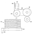
- FIG. 1 is a schematic diagram illustrating an example of a configuration suitable for detecting paper sheets in which a pickup roller is stacked on a stage, with respect to the storage device of FIG.
- FIG. 18 is a flowchart showing a payout process executed by the storage device of FIG. Or An example of a logical contradiction in which it is determined that a failure has occurred in the position detection sensor by the storage device of FIG.
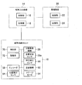
- the block diagram which shows the internal structure of the memory
- a banknote storage cassette 10 which is an embodiment of a paper sheet storage device according to the present invention stores banknotes 12 as paper sheets.
- the bill storage cassette 10 of the present embodiment is a paper sheet transfer device that delivers a paper sheet to a user as one of the elements constituting the paper sheet transfer system.
- This is a storage device that detachably attaches the bill 12 to the bill depositing / dispensing machine 14 of the automatic teller machine used, and stores the bill 12 by denomination.
- the banknote depositing and dispensing machine 14 includes a control unit 16 that controls the interlocking with the banknote storage cassette 10 and the banknote depositing and dispensing operation, and a storage unit that stores an interlocking program with the banknote storage cassette 10 and a banknote depositing and dispensing process program. 18 may be included.
- the banknotes stored in the banknote storage cassette 10 are carried out to the outside as required by the user or maintenance personnel.
- the banknote depositing / dispensing machine 14 is connected to a monitoring device 20 that remotely monitors the state and operation of the banknote depositing / dispensing machine 14 via a network or the like, and when an abnormality occurs in the banknote storage cassette 10 or the banknote depositing / dispensing machine 14 A signal notifying the occurrence of abnormality may be transmitted to the monitoring device 20.
- the monitoring device 20 may have a control unit 22 that controls the monitoring process of the banknote depositing and dispensing machine. Further, the monitoring device 20 may include a storage unit 24 for storing the monitoring program of the banknote depositing / dispensing machine 14 and information received from the banknote depositing / dispensing machine 14.
- the monitoring device 20 is installed in a facility such as a monitoring center that monitors a plurality of banknote depositing / withdrawing machines 14, and it is also possible to monitor the plurality of banknote depositing / dispensing machines 14 with one monitoring device 20.
- the banknotes 12 carried into the cassette 10 are stacked inside the banknote storage cassette 10, and the stacked banknotes 12 are separated one by one and fed out to the outside.
- a separation and accumulation mechanism 26 is provided.
- the separation and accumulation mechanism 26 is disposed in the vicinity of the banknote delivery port 28 provided on the deck of the banknote storage cassette 10.
- the separation and accumulation mechanism 26 has a feed roller 30 and a pinch roller 32.
- the feed roller 30 is disposed in the vicinity of the delivery port 28.
- the feed roller 30 has a stacking direction (indicated by a clockwise direction in FIG. 1) when the banknotes 12 are stacked around the feed roller shaft 30a, and a reverse direction when the banknotes 12 are fed out. In the feeding direction (displayed in the counterclockwise direction in FIG. 3).
- the pinch roller 32 is arranged opposite to the side of the feed roller 30.
- the pinch roller 32 is driven and rotated by the feed roller 30 around the pinch roller shaft 32a, and the banknote 12 carried in from the delivery port 28 and the banknote 12 carried out from the delivery port 28 are nipped between the feed roller 30 and conveyed. To do.
- the separating and accumulating mechanism 26 has a gate roller 34, and the gate roller 34 is installed below the feed roller 30.
- the gate roller 34 rotates around the gate roller shaft 34a in the opposite direction to the feed roller 30 when the banknotes 12 are stacked (displayed in the counterclockwise direction in FIG. 1), and draws the banknotes 12 into the banknote storage cassette 10.
- the gate roller 34 does not rotate when bills are fed.
- the gate roller 34 can separate the banknotes 12 fed out from the cassette 10 one by one.
- the separation / stacking mechanism 26 also has a pickup roller 36.
- the pickup roller 36 rotates around the pickup roller shaft 36a, and is provided in a direction on the upstream side of the feed roller 30 when the banknote 12 is fed out of the banknote storage cassette 10.
- the pickup roller shaft 36a is provided at a movable end, which is the other end of a support lever 38 (not shown in FIG. 1), which is rotatably supported at one end by the feed roller shaft 30a.
- the pickup roller 36 can rotate in both directions like the feed roller 30 and rotates in the same direction in conjunction with the feed roller 30.
- FIG. 4 shows an example of the configuration of the support lever 38 that is provided with the feed roller 30 and the pickup roller 36 and is not shown in FIG.
- the support lever 38 has a spring member 40, and the support lever 38 is urged by the spring member 40 toward the stage 42 on which a bill is placed.
- the spring member 40 which is a compression coil spring is provided on the upper portion of the support lever 38, but if the bias toward the stage 42 is realized, the type and installation location of the spring member 40 to be used Can be set arbitrarily.
- the movable end of the support lever 38 is provided with a press detection sensor 44 for detecting that the pickup roller 36 has pressed the uppermost banknote 12 on the stage 42 with a predetermined pressing force.
- the separating and accumulating mechanism 26 also has a tongue roller 46.
- the tongue piece roller 46 is a roller in which a plurality of tongue pieces 48 made of a flexible thin plate member formed of an elastic material such as synthetic rubber are radially arranged on the outer peripheral surface of the hub portion, and the tongue piece roller shaft 46a. Rotate around. With the rotation of the tongue piece roller 46, the rear end of the banknote 12 discharged from the feed roller 30 is pushed by the tip of the tongue piece 48 rotating around the tongue piece roller shaft 46a, knocked down, and further drawn. As a result, the banknotes 12 are stacked on the stage 42 which is a plate-like member inside the banknote storage cassette 10.
- the tongue roller 46 is integrated in which the tongue roller shaft 46a is arranged coaxially with the gate roller shaft 34a by a retracting mechanism 50 having an actuator, a link mechanism, and the like shown as internal components of the cassette 10 in FIG. It is configured to move between a position (see FIG. 1) and a retreat position (see FIG. 3) that does not hinder the conveyance of the banknote 12 fed out by the feed roller 30.
- a delivery monitoring sensor 28a is provided for detecting the bill 12 and counting the number of bills carried in or out.
- the delivery monitoring sensor 28a is, for example, an optical sensor in which the light emitting unit and the light receiving unit are arranged so as to face each other across the conveyance path of the banknote 12 carried in or out from the delivery port 28.
- the method of counting the bills 12 carried into or out of the bill storage cassette 10 is not limited to the method using the delivery monitoring sensor 28a.
- the banknote depositing / dispensing machine 14 to which the banknote storage cassette 10 is mounted may count the number of banknotes that have been transported and stored in the cassette 10 or carried out of the cassette 10.
- the stage 42 stacks the banknotes 12 by stacking the banknotes 12 fed from between the feed roller 30 and the gate roller 34 rotating in the stacking direction on the upper surface 42a of the stage.
- the stage 42 is configured to be movable up and down by a lifting mechanism using a stage motor 54 shown in FIG. 2 as a drive source.
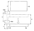
- a detection member 56 such as a light shielding plate is attached to one end of the stage 42 and moves as the stage 42 moves up and down.
- the upper end of the detection member 56 is attached so as to coincide with the height of the upper surface 42a of the stage.
- the length from the upper end to the lower end of the detected member 56, that is, the length in the moving direction of the stage 42 is represented by the reference symbol L1 in the drawings, and is also expressed as the detected member length L1 in the following description of the present invention. .
- An encoder 58 for detecting the amount of rotation of the shaft of the stage motor 54 is attached to the stage motor 54 of the lifting mechanism.
- the shaft of the stage motor 54 is directly connected to the stage 42 via an elevating mechanism. Therefore, the amount of movement of the stage 42 can be calculated from the amount of rotation of the stage motor 54 detected by the encoder 58.
- the encoder 58 is attached not only to the configuration built in the stage motor 54 but also to the outside of the stage motor 54 using, for example, a slit disk provided on a member such as a gear shaft constituting the lifting mechanism of the stage 42. You may take the structure.
- the banknote storage cassette 10 has a storage area 60 for storing banknotes 12 therein.
- the storage area 60 is formed by providing a sufficient space in the cassette 10 for storing the banknotes 12, for example, by providing a wall surface that separates the inside and the outside of the storage area 60.
- the raising / lowering of the stage 42 that accumulates the banknotes 12 is performed according to the height direction of the storage area 60.
- the position where the upper surface 60a of the storage area 60 is set is determined by pushing up the pickup roller 36 with the uppermost banknote 12 of the stacked banknotes stacked on the stage 42 when the stage 42 is raised, and detecting the press of the pickup roller 36 This is a position where the sensor 44 can detect the movable end of the support lever 38.
- this position where the press detection sensor 44 detects the banknote 12 is referred to as a banknote press position 60a.
- the lower surface 60b of the storage area 60 is set at the position of the stage upper surface 42a when banknotes are stacked on the stage 42 to the maximum extent that can be stored in the storage region 60.
- a stacking operation area 62 is provided as a space that should be secured when stacking the banknotes 12.
- the upper surface of the stacking operation area 62 is set to the upper surface 60a of the storage area 60, that is, the banknote pressing position 60a.
- the lower surface of the stacking operation area 62 is used to stack the banknotes 12 stacked at the tip of the tongue piece 48 of the tongue piece roller 46 when further stacking banknotes on the uppermost banknote 12 of the stacked banknotes stacked on the stage 42. It is set at a position where the rear end can be pulled.
- the height of the accumulation operation region 62 that is, the length in the stage moving direction is set to L2.
- the height of the integrated operation region is expressed as an integrated operation region length L2.
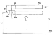
- a plurality of position detection sensors 64 are arranged in a line along the vertical direction so that the detected member 56 that moves up and down as the stage 42 moves up and down can be detected.
- the position detection sensor 64 is, for example, an optical sensor having a C-shape as shown in FIG. 5, and a groove 66 through which the detected member 56 attached to the stage 42 passes is formed. Further, on both side surfaces of the groove 66, a light emitting portion 68a and a light receiving portion 68b are disposed to face each other. In the case of such an optical sensor, the presence of the detected member 56 and thus the stage 42 is detected by detecting that the light emitted from the light emitting portion 68a ⁇ is shielded by the light receiving portion 68b. To detect.
- two position detection sensors 64a and 64b are provided in the upper part outside the storage area 60, and three position detection sensors 64c to 64e are provided in the vertical direction of the stage 42 in the lower part outside the storage area 60. Arranged in a row. The distance between the centers of the optical axes of the light emitting portions 68a disposed in the adjacent position detection sensors 64 is set to be longer than the detected member length L1.
- each position detection sensor 64 when each position detection sensor 64 is operating normally and the detected member 56 exists between the light emitting portions 68a of the position detection sensors 64, all the position detection sensors 64 emit light from the light receiving portions 68b. The light from the portion 68a is received, that is, in a bright state.
- the light receiving portion 68b of the sensor 64 when any one of the position detection sensors 64 detects the presence of the detected member 56, the light receiving portion 68b of the sensor 64 is not receiving light from the light emitting portion 68a, that is, a dark state. However, the other position detection sensors 64 are in a bright state.
- the position detection sensor 64 is an optical sensor, but any known sensor such as a microswitch can be used as the position detection sensor 64.
- the banknote storage cassette 10 controls each component of the banknote storage cassette 10 according to a command from the banknote depositing / dispensing machine 14 serving as a host device, and stacks and feeds out banknotes 12, failure determination processing of the position detection sensor 64, etc.
- the banknote storage cassette 10 also has a storage unit 72 for storing a program executed by the control unit 70, various data necessary for executing the program, a processing result by the control unit 70, and the like.
- the program stored in the storage unit 72 will be described in more detail with reference to FIG.
- the storage unit 72 includes an application program that causes the control unit 70 to execute a stacking process and a feeding process, a failure detection process for the position detection sensor 64, and a process for checking the number of stacked sheets and the number of stacking margins, which will be described later.
- a cassette processing program 74 including a cassette processing program for detecting the opening / closing of the door and causing the control unit 70 to record the opening / closing time and the number of stored sheets at that time is stored in advance.
- the banknote storage cassette 10 of this embodiment can operate as a stacking device, a banknote feeding device, a failure determination device, and the like.
- the storage unit 72 stores a position of the upper surface 42a of the stage 42 calculated from the lower surface 60b ⁇ of the storage area 60 based on the waveform count output from the encoder 58, that is, a stage position storage area 76 for storing the stage position Lp.
- the storage unit 72 further reserves in advance a storage number count area 78 used for counting the number of stored banknotes 12 stored in the banknote storage cassette 10 based on an output signal from the delivery monitoring sensor 28a.
- the storage unit 72 further includes a set value storage area 80 that stores various set values.
- the set values stored in the set value storage area 80 include, for example, the detected member length L1, the accumulation operation area length L2, the center of the optical axis and the storage area of the light emitting portion 68a of each position detection sensor 64a to 64e.
- the sensor position La thru Le which is the distance between the lower surface 60b (see Fig. 1), the storage length L3 which is the distance between the lower surface 60b and the upper surface 60a of the storage area (see Fig. 1), and attached to the stage motor 54
- Examples include a conversion coefficient when the count number by the encoder 58 is converted into the amount of movement of the stage 42, a thickness setting value Th that is a setting value of the thickness of one bill 12 stored in the bill storage cassette 10.
- the difference between the number of sheets accumulated on the stage 42 calculated by the confirmation process described later and the number of stored sheets counted by the delivery monitoring sensor 28a is caused by the failure of the position detection sensor 64.
- a predetermined allowable range used to determine that the difference is determined may be set and stored in advance.
- the predetermined allowable range may be an arbitrary range, but in this embodiment, the allowable range is 95% to 105% of the stored number.
- the control unit 70 of the banknote storage cassette 10 of this embodiment counts the output from the encoder 68 of the stage motor 54 of the lifting mechanism when the stage 42 is lifted and lowered in the stacking process and feeding process described later.
- the control unit 70 converts the count value into the movement amount of the stage 42 using the conversion coefficient stored in the storage unit 72.
- the control unit 70 adds the subtracted movement amount to the stage position Lp stored in the stage position storage area 76 of the storage unit 72 or subtracts it from the stage position Lp, so that the lower surface 60b of the storage area 60 is changed to the upper surface 42a of the stage 42.
- the stage position Lp is managed while updating the previous stage position Lp.
- the control unit 70 determines when any of the position detection sensors 64 changes from the dark state to the bright state or from the bright state to the dark state as the stage 42 is moved up and down, that is, any of the position detection sensors 64 is at the stage 42.
- the sensor position (any of La or Le) stored in the storage unit 72 of the position detection sensor 64 that detected the detected member 56 and the stage moving direction when the presence of the detected member 68 attached to the head is detected
- the stage position Lp as a new reference is calculated.
- the control unit 70 updates the stage position Lp stored in the stage position storage area 76 of the storage unit 72 to the newly calculated stage position Lp.
- the control unit 70 calculates the position of the sensor 64, for example, if the sensor 64 is the position detection sensor 64c, the sensor position Lc as the position of the upper surface 42a of the stage 42. Then, the control unit 70 resets the stage position Lp in the stage position storage area 76, and rewrites the calculated stage position Lc, which becomes a new reference, as the new stage position Lp.
- the control unit 70 adds the detected member length L1 to the position of the sensor 64, for example, if the sensor 64 is the position detection sensor 64c, to thereby position the upper surface 42a of the stage 42 (ie, , Stage position Lp) is calculated. Then, the control unit 70 resets the stage position Lp in the stage position storage area 76 and rewrites the calculated stage position as a new reference.
- the control unit 70 adds the detected member length L1 to the position of the sensor 64, for example, if the sensor 64 is the position detection sensor 64c, to thereby position the upper surface 42a of the stage 42 (ie, , Stage position Lp) is calculated. Then, the control unit 70 resets the stage position Lp in the stage position storage area 76 and rewrites the calculated stage position as a new reference.
- the control unit 70 calculates the position of the sensor 64, for example, if the sensor 64 is the position detection sensor 64c, the sensor position Lc as the position of the upper surface 42a of the stage 42. Then, the control unit 70 resets the stage position Lp in the stage position storage area 76, and rewrites the calculated stage position Lc, which becomes a new reference, as the new stage position Lp.
- the control unit 70 determines the stage position Lp in the stage position storage area 76 as the stage moving direction. Reset to a known sensor position considered. Therefore, the banknote storage cassette 10 according to the present invention can perform accurate management of the stage position Lp while eliminating the accumulated error of the movement amount accompanying the elevation of the stage 42 detected by the encoder 58.
- the control unit 70 executes the stacking process and the feeding process of the banknote 12 while managing the stage position Lp as described above.
- the control unit 70 of the banknote storage cassette 10 sets each part of the banknote storage cassette 10 in a waiting state for accumulation.
- control unit 70 moves the tongue roller 46 to the retracted position shown in FIG. 3 by the retracting mechanism 50 when the press detection sensor 44 of the pickup roller 36 does not detect the operating end of the support lever 38. Evacuate. Further, the control unit 70 rotates the stage motor 54 of the elevating mechanism to raise the stage 42, the position where the pressure detection sensor 44 is turned on, that is, the banknote 12 at the top of the stacked banknotes stacked on the stage 42. The stage 42 is moved so that the upper surface comes to the bill pressing position 60a (step S10).
- the press detection sensor 44 When the control unit 70 receives the stacking command from the banknote depositing / dispensing machine 14, the press detection sensor 44 is already in the ON state, that is, when the upper surface of the uppermost banknote 12 is already at the banknote pressing position 60a, The operation of S10 is omitted.
- the control unit 70 counts the output of the encoder 58 from the banknote pressing position 60a in the storage unit 72 separately from the count for managing the stage position Lp. While moving the stage 42 down. When the amount of movement of the stage 42 converted by multiplying the number of counts associated with the descending of the stage 42 by the conversion coefficient stored in the set value storage area 80 reaches the accumulation operation region length L2, the control unit 70 Thus, the stacking operation area 62 required for the stacking operation of the banknotes 12 is secured (step S20). Further, the control unit 70 returns the tongue piece roller 46 from the retracted position shown in FIG. 3 to the accumulation position shown in FIG. The movement of the tongue piece roller 46 to the accumulation position may be performed in parallel with the operation of securing the accumulation operation region 62.
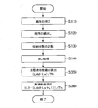
- the control unit 70 performs a calculation process of a stacking surplus number that is the number of banknotes 12 that can be further stacked on the stage 42 at the start of the stacking operation (step S30). More specifically, the control unit 70 determines the stage position Lp stored in the stage position storage area 76 of the storage unit 72 and the thickness of the banknote 12 stored in the set value storage area 80. The set value Th is read out, and the stage position Lp, which is the distance between the lower surface 60b ⁇ of the storage area 60 and the upper surface 42a ⁇ ⁇ ⁇ ⁇ of the stage 42, is divided by the thickness set value Th to calculate the number of accumulation margins at the start of the accumulation operation.
- control unit 70 transmits the calculated accumulation margin number via the banknote depositing / dispensing machine 14 to the monitoring device 20 of the monitoring center that remotely monitors the banknote depositing / dispensing machine 14.
- control unit 70 that has transmitted the calculated accumulation margin number rotates the feed roller 30 and the pickup roller 36 in the accumulation direction, and rotates the pinch roller 32 and the tongue piece roller 46 in the opposite direction.
- the preparation for receiving the banknote 12 is completed (step S40), and the banknote storage cassette 10 waits for the banknote 12 to be carried from the delivery port 28.
- the carried banknote 12 is detected by the delivery monitoring sensor 28a and then sandwiched between the feed roller 30 and the pinch roller 32, and further along the guide member (not shown) by the feed roller 30. Are discharged to the accumulation operation region 62.
- the rear end of the discharged banknote 12 is pushed by the tongue 48 of the tongue roller 46, knocked down, and further pulled and stacked on the uppermost banknote 12 stacked on the stage 42 ( Step S50). By repeating such a stacking operation, the banknotes 12 are continuously stacked on the stage.
- the control unit 70 increments the stored number count area 78 of the storage unit 72 by one and counts the stored number ( Step S60). Further, the control unit 70 uses the thickness set value Th stored in the set value storage area 80 to calculate a decrease in the stacking operation area length L2 due to the newly stacked banknote 12, and calculates the decrease. Converted into the rotation amount of the encoder 58. The control unit 70 controls to always secure the accumulation operation region 62 while lowering the stage 42 in accordance with the converted rotation amount of the encoder 58.
- the control unit 70 stops the separation and stacking mechanism 26 and operates the retracting mechanism 50 so that the stacked banknotes do not move. Evacuate. Further, the control unit 70 rotates the stage motor 54 and raises the stage 42 until the press detection sensor 44 of the pickup roller 36 is turned on. When the press detection sensor 44 is turned on, the stacked banknotes are sandwiched between the stage 42 and the pickup roller 36, and the uppermost banknote 12 is positioned at the banknote pressing position 60a60 (step S70). .
- the control unit 70 that has recognized that the stacked banknotes are sandwiched between the stage 42 and the pickup roller 36 by the press detection sensor 44 performs a calculation process of the number of stacked banknotes at the end of stacking (step S80). More specifically, in step S80, the control unit 70 sets the stage position Lp when the stacked banknotes on the stage 42 are sandwiched between the stage 42 and the pickup roller 36 to the stage position storage area 76 of the storage unit 72. Read from. Further, the control unit 70 reads the storage length L3 stored in the set value storage area 80 and the thickness set value Th of the banknote 12.
- control unit 70 subtracts the stage position Lp from the storage length L3 to calculate the distance (L3-Lp) between the upper surface 60a of the storage region 60 and the upper surface 42a of the stage 42. By dividing the calculated distance (L3-Lp) by the thickness setting value Th, the control unit 70 calculates the number of stacked banknotes stacked on the stage 42 at the end of stacking.
- control unit 70 transmits the calculated number of accumulated banknotes and the number of stored sheets counted in the stored number counting area 78 of the storage unit 72 to the monitoring device 20 of the monitoring center via the banknote depositing / dispensing machine 14, The accumulation process is terminated. As described above, the stacking process of the banknotes 12 in the banknote storage cassette 10 of the present embodiment is executed.
- the control unit 70 of the bill storage cassette 10 retracts when the press detection sensor 44 of the pickup roller 36 is in the OFF state.
- the mechanism 50 is controlled to retract the tongue roller 46 to the retracted position, and the stage motor 54 of the lifting mechanism is rotated to raise the stage 42.
- the control unit 70 sets the stage so that the press detection sensor 44 is turned on, that is, the upper surface of the banknote 12 at the top of the stacked banknotes stacked on the stage 42 is placed at the banknote pressing position 60a. 42 is moved (step S110). If the pressure detection sensor 44 is already in the ON state, the operation related to step S110S is omitted.
- the control unit 70 presses the pickup roller 36 and the pickup roller 36 while pressing the stacked banknotes on the stage 42 with the pickup roller 36.
- the feed roller 30 is rotated in the feeding direction (counterclockwise in FIG. 3), and the uppermost banknote 12 is fed between the feed roller 30 and the gate roller.
- the gate roller 34 since the gate roller 34 does not rotate, the uppermost banknote 12 is fed out by the feed roller 30, while the second and subsequent banknotes 12 are not fed out along with the uppermost banknote. As a result, the stacked banknotes 12 are separated one by one and fed out from the storage area 60.
- the banknote 12 separated into one sheet and fed out from between the feed roller 30 and the gate roller 34 is sandwiched between the feed roller 30 and the pinch roller 32 and conveyed toward the delivery port 28 along a guide member (not shown). .
- the banknotes 12 transported in the direction of the delivery port 28 are detected by the delivery detection sensor 28a and then carried out of the banknote storage cassette 10 from the delivery port 28.
- the steps so far correspond to the bill feeding operation shown in step S120 of FIG.
- the banknotes 12 on the stage 42 are continuously fed out by repeating the feeding operation in step S120. During this feeding operation, every time the delivery monitoring sensor 28a detects the newly fed banknote 12, the control unit 70 subtracts one from the count number stored in the storage number count area 78 of the storage unit 72. The number of stored sheets is counted (step S130).
- the pickup roller 36 is eventually lowered and the press detection sensor 44 is turned off.
- the control unit 70 detects that the pressure detection sensor 44 is in the OFF state, the control unit 70 rotates the stage motor 54 and raises the stage 42 until the pressure detection sensor 44 is turned on again. By repeating the position control of the stage 42, the control unit 70 performs control so that the position of the uppermost banknote 12 of the stacked banknotes is always maintained at the banknote pressing position 60a ⁇ ⁇ according to the number of banknotes 12 fed out.
- step S140 the control unit 70 stops the separation and accumulation mechanism 26.
- the control unit 70 executes a returning process for returning the banknote waiting to be fed back to a normal stacking state (step S140).
- step S140 the return process in step S140 is as follows.
- the controller 70 rotates the stage motor 54 and lowers the stage 42 until it reaches the accumulation operation region length L2, thereby securing the accumulation operation region 62. Further, the control unit 70 moves the position of the tongue piece roller 46 from the retracted position to the accumulation position. Thereafter, as shown in FIG. 1, the controller 70 rotates the feed roller 30 and the pickup roller 36 in the stacking direction, while rotating the tongue roller 46 in the direction opposite to the feed roller 30 and the pickup roller 36.
- the control unit 70 stops the feed roller 30, the pickup roller 36, and the tongue piece roller 46 after returning the waiting banknotes to the uppermost part of the stacked banknotes by the tongue piece 48 that rotates with the rotation of the tongue piece roller 46.
- the tongue piece roller 46 is moved to the retracted position.
- the control unit 70 rotates the stage motor 54 to raise the stage 42 until the press detection sensor 44 of the pickup roller 36 is turned on, and the stacked banknotes are sandwiched between the stage 42 and the pickup roller 36.
- the uppermost banknote 12 is positioned at the banknote pressing position 60a.
- the control unit 70 that has finished the banknote return process subsequently performs a process of calculating the accumulated banknote number at the end of the payout. That is, the control unit 70 lowers the stage 42 while counting the output of the encoder 58 from the bill pressing position separately from the count for managing the stage position Lp.
- the control unit 70 reads the stage position Lp stored in the stage position storage area 76 of the storage unit 72 and the bill thickness set value Th stored in the set value storage area 80.
- the control unit 70 that has read out necessary information from the storage unit 72 divides the stage position Lp by the thickness setting value Th, and calculates the number of bills that can be accumulated at the end of feeding (step S150).
- the control unit 70 that has calculated the stacking surplus number subsequently executes a calculation process (step S160) of the banknote stacking number at the end of feeding. That is, the control unit 70 rotates the stage motor 54 again and raises the stage 42 until the press detection sensor 44 of the pickup roller 36 is turned on. As a result, the stacked banknotes are sandwiched between the stage 42 and the pickup roller 36, and the uppermost banknote 12 is positioned at the banknote pressing position.
- the control unit 70 reads the stage position Lp at this time from the stage position storage area 76 of the storage unit 72, and reads the storage length L3 and the bill thickness setting value Th from the set value storage area 80.
- the control unit 70 that has read the necessary information from the storage unit 72 subtracts the stage position Lp from the storage length L3 to calculate the distance (L3-Lp) between the upper surface 60a of the storage region 60 and the upper surface 42a of the stage 42. .
- the control unit 70 that has calculated the distance (L3-Lp) further divides the calculated distance (L3-Lp) by the thickness setting value Th, and accumulates the number of banknotes accumulated at the end of the payout accumulated on the stage 42. Is calculated (step S160).
- the control unit 70 that has completed the above processing uses the monitoring center monitoring device via the banknote depositing / dispensing device 14 to calculate the accumulated margin number, the accumulated number, and the stored number counted in the stored number count area 78 of the storage unit 72. 20 to finish the feeding process by the current feeding command.
- the monitoring device 20 indicates the number of stacked sheets, the number of stacked sheets, and the stored number at the end of stacking or at the end of feeding received from the banknote storage cassette 10 via the banknote depositing / dispensing machine 14.
- the accumulated number of banknotes 12 stacked in the banknote storage cassette 10 of that denomination, the number of stackable margins, and the number of stored sheets are stored in time series.
- the monitoring device 20 issues a near-full alarm of the bill storage cassette 10 to notify the staff of the monitoring center at a certain time before the accumulated number of bill storage cassettes 10 becomes full, that is, when the bill storage cassette 10 exceeds a predetermined near full threshold.
- the alarm transmission method may be any method such as displaying a warning on the screen of the display unit of the monitoring center.
- the staff member who has confirmed the near-full alarm transports the banknote storage cassette 10 loaded with a predetermined number of banknotes 12 to the banknote depositing / dispensing machine 14 and replaces it with the banknote storage cassette 10 in which the near-full alarm has been issued.
- the monitoring device 20 also issues a near-end alarm for the bill storage cassette 10 by an arbitrary method at a certain time before the number of accumulated bill storage cassettes 10 becomes zero, that is, when the bill storage cassette 10 falls below a predetermined near-end threshold. Notify the staff.
- the staff member who has confirmed the near-end alarm transports the banknote storage cassette 10 loaded with a predetermined number of banknotes 12 to the banknote depositing / dispensing machine 14 and replaces it with the banknote storage cassette 10 in which the near-end alarm has been issued.
- the control unit 70 performs the stacking process or the feeding process. During this, a failure determination process for determining a failure of the position detection sensor 64 based on a logical contradiction in the detection of the detected member 56 by the position detection sensor 64 is executed.
- the specific position detection sensor 64 should detect the detected member 56 when the detected member length L1 is considered in the stage position Lp calculated by the amount of movement of the stage 42 detected by the encoder 58.
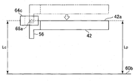
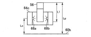
- an example of a logical contradiction is that the specific position detection sensor 64 does not detect the detected member 56 as shown in FIG.
- the control unit 70 determines that the position detection sensor 64c that should originally detect the detected member 56 has failed.
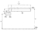
- the position detection sensor 64 that detects the detected member 56 does not exist at the stage position Lp calculated by the amount of movement of the stage 42 detected by the encoder 58 during the dredging process even if the detected member length L1 is taken into consideration. However, as shown in FIG. 14, at least one of the position detection sensors 64 is in a dark state as an example of a logical contradiction. In the case of FIG. 14, the control unit 70 determines that the position detection sensor 64c that erroneously detected the detected member 56 has failed.
- the position detection sensor 64 that detects the detected member length L1 at the stage position Lp calculated by the amount of movement of the stage 42 detected by the encoder 58 detects the detected member 56.
- at least one of the other position detection sensors 64 is in a dark state as an example of logical contradiction.
- the position detection sensors 64 in this embodiment are arranged at intervals longer than the detected member length L1, it is impossible for two or more position detection sensors 64 to detect the detected members 56 at the same time. is there.
- the control unit 70 is a position in the other position detection sensors 64 that is in a dark state. It is determined that all the detection sensors (sensor 64d in FIG. 15) have failed.
- control unit 70 counts the number of banknotes 12 carried into or out of the banknote storage cassette 10 by the output signal output from the delivery monitoring sensor 28a, and adjusts the number of banknotes 12 counted.
- the stored number Bst is counted in the stored number count area 78 of the storage unit 72.
- the controller 70 can determine whether the sensor 64 has failed using the stored number Bst .
- the control unit 70 compares the counted stored number B st with the accumulated number calculated by the formula (L3-Lp) / Th at the end of accumulation or at the end of feeding. If the accumulated number is different from the stored number Bst beyond a predetermined allowable range stored in the set value storage area 80, it is determined that a logical contradiction has occurred.
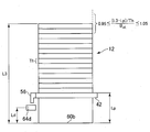
- the allowable range is 95% or more and 105% or less of the stored number B st as in this embodiment, the calculated accumulated number is less than 95% of the stored number B st as shown in FIG. If it exceeds 105%, the control unit 70 determines that the position detection sensor 64 that has become the reference for the latest rewriting of the stage position Lp has failed.
- the control unit 70 can calculate the stacking height based on the number of stored sheets stacked on the stage 42. Therefore, if the controller 70 subtracts the stacking height from the storage length L3 of the storage region 60, the banknote 12 is sandwiched between the stage 42 and the pickup roller 36 at the end of stacking or at the end of feeding. The position of the stage 42 when it is pushed in can be calculated.
- the control unit 70 can specify the position detection sensor 64 that should detect the detected member 56. Of course, the control unit 70 can also specify that there is no position detection sensor 64 that should detect the member 56 to be detected. In view of the position of the stage 42 in consideration of the detected member length L1 and the presence or absence of the position detection sensor 64 that should detect the detected member 56, the control unit 70 results in a sensor as shown in FIGS. When a logical contradiction with respect to 64 is detected, it is determined that the position detection sensor 64 in a logically contradictory state is out of order.
- control unit 70 may stop the operation of the banknote storage cassette 10.
- the control unit 70 that has stopped the operation of the banknote storage cassette 10 transmits a notification to the effect that the position detection sensor 64 has failed to the banknote deposit and withdrawal machine 14.
- the banknote depositing / dispensing machine 14 that has received the failure occurrence notification stops its operation.
- the failure of the position detection sensor 64 can be easily determined by the logical contradiction that occurs between the stage position Lp and the detected member 56 detected by the position detection sensor 64. Furthermore, according to the present embodiment, the number of stacked banknotes 12 and the number of stackable margins in the banknote storage cassette 10 can be easily calculated.
- the administrator can immediately prepare an alternative banknote storage cassette 10 for repair. Then, it is possible to always use the cassette 10 that operates normally without the banknote storage cassette 10 in which the position detection sensor 64 has failed. As a result, it is easy to draft an operation plan for the banknote storage cassette 10 to reduce the waste of banknote replenishment work through efficient operation of the exchange of the banknote storage cassette 10 and waste due to erroneous detection of banknotes in the banknote storage cassette 10 It becomes possible to do.
- the control unit 70 notifies the monitoring device 20 that the position detection sensor 64 has failed and stops the operation of the banknote storage cassette 10, the number of stacked sheets and the number of stackable margins in the banknote storage cassette 10 can be accurately determined.
- the banknote storage cassette 10 is not operated without being grasped. As a result, it is possible to stop the transaction in the middle of a transaction due to a sudden shortage of banknotes, or to stop the banknote depositing / dispensing machine 14 for a long time due to the occurrence of a jam due to the stacking of banknotes 12 when there is no stackable number. Can be prevented. This advantage leads to improved customer convenience.
- the thickness setting value Th of the banknote 12 can be set in advance, so that the banknote storage cassette 10 can calculate the number of stacked sheets and the stackable number of sheets according to the thickness of various banknotes. Is possible. When handling banknotes with different thicknesses for each country such as foreign banknotes, it is not necessary to change the position of the position detection sensor 64 for each country, so it is difficult to change the position of the position detection sensor 64. Particularly useful for cassette 10.
- the controller 70 is configured to stop the operation of the bill storage cassette 10 when it is determined that the position detection sensor 64 has failed.
- the control unit 70 may be configured to continue the operation of the banknote storage cassette 10 when determining a failure and only transmit a failure occurrence notification to the monitoring device 20 of the monitoring center.
- the administrator of the banknote depositing / dispensing machine 14 confirms the failure occurrence notification displayed on the monitoring device 20 at the monitoring center, prepares an alternative bill storage cassette 10 and transports it to the site. It may be exchanged for the bill storage cassette 10 that has been issued. Repair of the banknote storage cassette 10 in which the failure has occurred is performed at an optimum timing at the monitoring center.
- the control unit 70 of the cassette 10 may execute a degenerate operation in which the position detection sensor 64 in which the failure has occurred is functionally excluded. That is, the control unit 70 ignores the output signal from the position detection sensor 64 where the failure has occurred, and continues the operation of the bill storage cassette 10 while managing the stage position Lp according to the amount of movement of the stage 42 detected by the encoder 58. It may be. Accordingly, the operation stop time of the banknote depositing / dispensing machine 14 can be minimized, and the operating efficiency of the banknote depositing / dispensing machine 14 can be improved.
- banknote storage cassette 100 ⁇ according to another embodiment of the present invention will be described with reference to FIG. Throughout this patent application, like reference numerals are used to indicate like elements, and a repeated description thereof is avoided.
- the configuration of the banknote storage cassette 100 ⁇ according to the embodiment shown in FIG. 17 may be substantially the same as the configuration of the banknote storage cassette 10 ⁇ according to the embodiment shown in FIG. 1.
- the position detection sensor 164 in the bill storage cassette 100 differs from the position detection sensor 64 in the embodiment of FIG.
- the configuration of the position detection sensor 164 ⁇ ⁇ may be the same as the configuration of the position detection sensor 64 shown in FIG. 5, and thus has the same function as the position detection sensor 64 for detecting the presence of the detected member 56.
- the position detection sensor 164 In the banknote storage cassette 100, seven position detection sensors 164a to 164g are arranged outside the storage area 60 in one row along the ascending / descending direction of the stage 42. More specifically, the position detection sensor 164 is arranged. explain. In the position detection sensor 164 of this embodiment, the distance between the centers of the optical axes of the light emitting portions 68a included in the adjacent sensors 164 is longer than the detected member length L1 and is detected to the integrated operation region length L2. The interval is set to be less than the length including the member length L1.
- any one of the position detection sensors 164a to 164g is arranged to detect the detected member 56 without fail.
- the position detection sensors 164a to 164g of the embodiment shown in FIG. 17 are all arranged at equal intervals. However, the sensors are arranged at unequal intervals as long as they are longer than the detected member length L1 and within an interval shorter than the integrated operation region length L2 plus the detected member length L1. There may be.
- the internal configuration of the bill storage cassette 100 ⁇ ⁇ ⁇ and the connection relationship with other devices may be the same as the block diagram of the previous embodiment shown in FIG. 2. That is, also in this embodiment, a storage unit 172 having the same configuration and function as the storage unit 72 is mounted in the banknote storage cassette 100. The programs stored in the storage unit 172 ⁇ of this embodiment are shown in FIG.
- the cassette processing program 74 is stored in the storage unit 172 of the present embodiment, and the stored sheet count area 78 and the set value storage area 80 are secured.
- the rotation amount count area 176 for counting the number of waveform counts output from the encoder 58 is used to calculate the amount of movement of the stage 42, and the number of accumulated bills 12 and the number of accumulated bills 12.
- the rotation amount count area 176 it is also possible to simultaneously count the output counts from different starting points in accordance with a command from the control unit 70.
- sensor positions Laa to Lgg that are distances between the center of the optical axis of the light emitting portion 68a of each of the detection sensors 164a to 164g and the lower surface 60b of the storage area 60 are preset and stored. Has been.
- the control unit 70 confirming that the uppermost banknote 12 is at the banknote pressing position 60a lowers the stage 42 while counting the output of the encoder 58 of the stage motor 54 starting from the banknote pressing position 60a in the storage unit 72. .
- the control unit 70 stops the stage 42 and performs the accumulation operation.
- the area 62 is secured (step S220).
- the control unit 70 further moves the tongue piece roller 46 from the retracted position to the accumulation position.
- step S230 the control unit 70 executes a process for calculating the number of accumulated banknotes 12 (step S230).
- the operation of step S230 will be described in detail below.
- the control unit 70 monitors output signals from the position detection sensors 164a to 164g. If the control unit 70 detects that the position detection sensor 164 ⁇ ⁇ has changed from the bright state to the dark state or from the dark state to the bright state before the accumulation operation area 62 is secured, the control unit 70 The count number of the output from the encoder 58 from the position until the position where the accumulation operation area 62 is secured is counted in the rotation amount count area 176 mm separately from the count for measurement of the accumulation operation area length L2 in step S220. .
- the control unit 70 measures the encoder 58 counted in the rotation amount count area 176 from the position of the position detection sensor 164 that detected the detected member 56 until the accumulating operation area 62 is secured. Read the count number. At the same time, the control unit 70 detects the detected member 56 stored in the set value storage area 80, the sensor position of the position detection sensor 164, the conversion coefficient, the detected member length L1, and the bill 12 thickness setting value Th. Is read.
- the control unit 70 determines whether the position detection sensor 164d detects the position detected by the position detection sensor 164d. Start counting. Thereafter, when the position detection sensor 164d changes from the dark state to the bright state, the control unit 70 once clears the count number in the rotation speed count area 176 and starts counting from the detection position again.
- the control unit 70 counts the number counted in the rotation amount count area 176 starting from the detection position by the sensor 164d, the sensor position Ldd of the position detection sensor 164d, the conversion coefficient, the length of the detected member L1 and thickness setting value Th of banknote 12 are read out.
- the control unit 70 calculates the movement amount Ls from the position detection sensor 164d by multiplying the count number read from the rotation amount count area 176 by the conversion coefficient.
- the change of the detection state from the dark state to the bright state is a change due to the upper end of the detection target member 56 being lowered, that is, the upper surface 42a of the stage 42. Therefore, the control unit 70 calculates the position of the upper surface 42a of the stage 42 by subtracting the movement amount Ls from the sensor position Ldd.
- the calculated value (Ldd ⁇ Ls) obtained by subtracting the movement amount Ls from the sensor position Ldd is the distance between the lower surface 60b of the storage area 60 and the upper surface 42a of the stage 42. Therefore, the control unit 70 can calculate the accumulation margin number at the start of the accumulation operation by dividing the calculated value (LddL ⁇ Ls) by the thickness setting value Th.
- the controller 70 transmits the calculated accumulation margin number to the monitoring device 20 of the monitoring center via the banknote depositing / dispensing machine 14.
- the banknote storage cassette 100 ⁇ performs the banknote acceptance preparation, the banknote stacking process, the stored number counting process, and the stacked banknote sandwiching process, which may be the same as the operations performed in the previous embodiment, that is, steps S40 to S70. .
- step S280 the control unit 70 executes a process for calculating the number of stacked banknotes 12 at the end of stacking.
- the operation of step S280 will be described in detail below.
- the controller 70 monitors the output signals from the position detection sensors 164a to 164g during the sandwiching operation of the stacked banknotes shown in step S70.
- the control unit 70 determines the position of the stacked banknotes from the position of the sensor 164 that detected the detected member 56.
- the count of the output from the encoder 58 until the position where the clamping is finished is counted in the rotation amount count area 176 mm.
- the control unit 70 counts the number of encoders 58 counted in the rotation amount count area 176 until the stacking operation area 62 is secured from the position of the position detection sensor 164 that detected the detected member 56. Is read.
- the control unit 70 detects the sensor position of the position detection sensor 164 that has detected the detected member 56 stored in the set value storage area 80, the conversion coefficient, the detected member length L1, the storage length L3, and the bill 12 Read the thickness setting value Th. Then, the control unit 70 calculates the number of stacks at the end of stacking based on various numerical values read from the storage unit 72 and the stage moving direction.
- the control unit 70 detects the position detected by the position detection sensor 164d. Start counting. Thereafter, when the position detection sensor 164d changes from the dark state to the bright state, the control unit 70 once clears the count number in the rotation speed count area 176 and starts counting from the detection position again.
- the control unit 70 counts the number counted in the rotation amount count area 176 from the detection position by the sensor 164d, the sensor position Ldd of the position detection sensor 176d, the conversion coefficient, and the length of the detected member L1, the storage length L3, and the bill thickness set value Th are read out.
- the control unit 70 calculates the movement amount Ls from the position detection sensor 176d by multiplying the count number read from the rotation amount count area 176 by the conversion coefficient.
- the control unit 70 calculates the position of the upper surface 42a of the stage 42 by adding the movement amount Ls and the detected member length L1 to the sensor position Ldd.
- the control unit 70 subtracts the calculated value of the stage upper surface 42a obtained from the formula (Ldd + Ls + L1) from the storage length L3 to calculate the distance between the upper surface 60a of the storage region 60 and the upper surface 42a of the stage 42. Then, the control unit 70 divides the calculated distance between the storage area upper surface 60a and the stage upper surface 42a by the thickness setting value Th. Thereby, the control unit 70 can calculate the number of stacked sheets at the end of stacking.
- the control unit 70 transmits the calculated number of accumulated sheets and the number of stored sheets counted in the stored number counting area 78 of the storage unit 72 to the monitoring device 24 of the monitoring center via the banknote depositing / dispensing machine 14, and the accumulation according to the current accumulation command is performed. End the process.
- the banknote 12 stacking process is executed by the banknote stacking cassette 100 ⁇ according to the present embodiment in the above procedure.
- step S110 the operation performed from the time when the control unit 70 receives the payout command until the return processing of the payout waiting bill is completed is step S110 ⁇ of the operations in the payout processing of the previous embodiment. This may be the same as step S140. Therefore, a duplicate description of these operations is avoided.
- the control unit 70 that has finished the process of returning the banknotes waiting to be fed subsequently executes a calculation process (step S350) of the accumulated margin number of banknotes at the end of the feeding. That is, the control unit 70 lowers the stage 42 while counting the output of the encoder 58 from the banknote pressing position 60a ⁇ in the storage unit 72. When the amount of movement of the stage 42, which is converted by multiplying the count associated with the descending of the stage 42 by the conversion coefficient stored in the set value storage area 80, reaches the accumulation operation area length L2, the control unit 70 Is stopped, and the accumulation operation area 62 is secured.
- control unit 70 calculates the stacking surplus number at the end of feeding by the same method as in step S230 at the start of the stacking operation described in FIG.
- the control unit 70 that has calculated the stacking surplus number according to step S350 subsequently executes processing for calculating the stacking number of banknotes at the end of feeding (step S360). That is, the control unit 70 rotates the stage motor 54 again and raises the stage 42 until the press detection sensor 44 of the pickup roller 36 is turned on. As a result, the stacked banknotes are sandwiched between the stage 42 and the pickup roller 36, and the uppermost banknote 12 is positioned at the banknote pressing position 60a. At this time, the control unit 70 calculates the number of stacked sheets at the end of feeding by the same method as described in step S280 at the end of stacking.
- the control unit 70 transmits the calculated number of accumulated sheets, the number of accumulated sheets, and the number of stored sheets counted in the storage number counting area 78 of the storage unit 72 to the monitoring device 20 of the monitoring center via the banknote depositing / dispensing machine 14, The feeding process by the feeding command is terminated. Since the subsequent treatment at the monitoring center may be the same as that in the previous embodiment, the redundant explanation is avoided.
- control unit 70 of the bill storage cassette 100 performs a logical contradiction in the detection of the detected member 56 by the position detection sensor 164.
- a failure determination process for determining a failure of the position detection sensor 164 is executed.
- control unit 70 determines that there is a faulty position detection sensor 164 ⁇ ⁇ ⁇ is as follows.
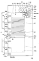
- FIG. 22 it is an example of a logical contradiction that at least two position detection sensors 164 ⁇ ⁇ are simultaneously in a dark state during processing.
- the position detection sensors 164 are arranged at intervals longer than the detected member length L1, two or more position detection sensors 164 (sensors 164c and 164d in FIG. 22) simultaneously detect the detected member 56. Because things can never happen.
- the control unit 70 determines that any or all of the position detection sensors 164 ⁇ ⁇ that simultaneously detect the detected members 56 have failed.
- the position detection sensor 164 is arranged at an interval L4 that is less than the length L2 of the accumulation operation region plus the length L1 of the detected member.
- One of the position detection sensors 164 ⁇ ⁇ must detect the detected member 56 during the raising / lowering of the banknote 12 in the accumulation operation area 62. Since none of the position detection sensors 164 ⁇ ⁇ can detect the detected member 56 can occur, in this case, the control unit 70 determines that any or all of the position detection sensors 164 ⁇ are out of order. .
- the control unit 70 counts the number of banknotes 12 carried into or out of the banknote storage cassette 100 based on the output signal output from the delivery monitoring sensor 28a, and adjusts the number of banknotes 12 counted.
- the stored number Bst is counted in the stored number count area 78 of the storage unit 72. Using this stored number Bst , the control unit 70 can determine whether the position detection sensor 164 has failed.
- control unit 70 explained in the above example (7) at the time of calculating the stored number B st counted in the stored number count area 78 and the number of stacked sheets at the end of stacking or at the end of feeding (steps S280 and S360).
- the number of accumulated sheets calculated when no logical contradiction occurs is compared.
- the control unit 70 has a logical contradiction in the accumulated number.
- the allowable range is set to 95% or more and 105% or less of the stored number B st as in the present embodiment, the calculated accumulated number is less than 95% of the stored number B st as shown in FIG. If there is or exceeds 105%, the control unit 70 determines that the position detection sensor 164 (sensor 164f in FIG. 24), which is the basis of the accumulated number calculation, has failed during the accumulated number calculation process.
- control unit 70 calculates the number of stored sheets counted by the delivery monitoring sensor 28a similarly to the failure determination processing example (5) performed in the previous embodiment. Based on the position of the stage 42, the failure determination process described in the following examples (9) to (11) can be executed.
- the control unit 70 determines that the position detection sensor 164 has failed, as in the previous embodiment, the control unit 70 stops the operation of the bill storage cassette 100 ⁇ ⁇ and monitors the monitoring center.
- a notification that a failure has occurred in the position detection sensor 164 ⁇ ⁇ may be transmitted to the device 20.
- the control unit 70 may transmit a notification that a failure has occurred in the position detection sensor 164 ⁇ to the monitoring device 20 while continuing the operation of the bill storage cassette 100.
- the action taken at the monitoring center that has received the notification of the occurrence of the failure may be the same as in the previous embodiment, so a duplicate explanation is avoided.
- the control unit 70 when the operation of the bill storage cassette 100 ⁇ ⁇ is continued when it is determined that the position detection sensor 164 ⁇ has failed, the control unit 70 continues the operation by degenerating the position detection sensor 164 ⁇ where the failure occurred. It is also possible to make it. In this case, the control unit 70 ignores the output signal from the position detection sensor 164 ⁇ ⁇ which has been degenerated by detecting the occurrence of a failure, and manages the banknote while managing the position of the stage 42 based on the amount of movement of the stage 42 detected by the encoder 58. Continue to operate the storage cassette 100 ⁇ ⁇ .
- banknote storage cassette 10 according to still another embodiment of the present invention will be described. Since the basic components of the banknote storage cassette 10 according to this embodiment may be the same as the components of the cassette 10 shown in FIGS. 1 to 6, repeated description is avoided.
- the storage unit 72 of this embodiment will be described with reference to FIG.
- the storage unit 72 shown in FIG. 25 has a cassette processing program 74, a stage position storage area 76, a stored sheet count area 78, and a set value storage area 80, which may be the same as the storage unit 72 of FIG.
- a transaction history storage area 182 for storing the distance (L3-Lp) between the two as transaction history information is also secured in advance.
- the control unit 70 performs the processing of steps S10 to S80 illustrated in the flowchart of FIG. After that, the number of stored items at the end of the deposit transaction, etc. counted in step S60, and the distance (L3-Lp) between the upper surface 60a of the storage region 60 and the upper surface 42a of the stage 42 calculated in step S80 Is stored in the transaction history storage area 182 of the storage unit 72.
- control unit 70 transmits the calculated number of accumulated sheets and the number of stored sheets counted in the stored number counting area 78 of the storage unit 72 to the monitoring device 20 of the monitoring center via the banknote depositing / dispensing machine 14, and this accumulation command The accumulation process is terminated.
- the control unit 70 When the banknote storage cassette 10 of the present embodiment receives a banknote feeding command from the banknote depositing / dispensing machine 14 and performs the feeding process, the control unit 70 performs the processes of steps S110 to S160 shown in the flowchart of FIG. , The number of stored sheets at the end of the withdrawal transaction, etc., counted in step S130, and the distance (L3-Lp) between the upper surface 60a of the storage area 60 and the upper surface 42a of the stage 42 calculated in step S160, The transaction history information is stored in the transaction history storage area 182 of the storage unit 72.
- control unit 70 transmits the calculated accumulated number and accumulated margin number and the stored number counted in the stored number counting area 78 of the storage unit 72 to the monitoring device 20 of the monitoring center via the banknote depositing / dispensing machine 14, The feeding process by the current feeding command is terminated.
- the processing performed by the monitoring center that has received information such as the number of stacked sheets after completion of the stacking process or the feeding process may be the same as in the previous embodiment, so that repeated description is avoided.
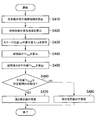
- a flowchart shown in FIG. 26 shows a process performed by the control unit 70 to update the thickness setting value Th of the banknote 12 stored in the setting value storage area 80 of the storage unit 72 during the execution of such a cassette process. Will be described with reference to FIG.
- control unit 70 obtains transaction history information for the past 10 transactions including the current transaction from the transaction history storage area 182 of the storage unit 72. Read (Step S410).
- control unit 70 changes the number of stored sheets between two consecutive transactions, that is, the number of banknotes 12 newly carried in from the delivery port 28, or the number of banknotes 12 newly carried out from the delivery port 28.
- the delivery number is calculated (step S420).
- the control unit 70 calculates the amount of change in the stage position Lp between two consecutive transactions, that is, the amount of change ⁇ Lp in the distance between the stage position Lp and the upper surface 60a of the storage area 60, along with the processing in step S420 (step S430). ).
- the control unit 70 divides the change amount ⁇ Lp of the stage position Lp by the delivery number, and calculates the thickness Th cal of the banknote 12 between the transactions (step S440).
- the control unit 70 calculates the average value Th ave of the banknote 12 calculated respectively by transaction history information for the past 10 trading partial thickness Th cal averaged to bill thickness (step S450).
- Control unit 70 calculates an average value Th ave of the bill thickness is carried out followed by updating of the thickness set value Th of the banknote 12 stored in the set value storage area 80.
- Control unit 70 an average value Th ave of the bill thickness of the last 10 transactions, compared to its time in the set value storage thickness set value is stored in the area 80 Th, the average value Th ave is the set value Th
- it is determined whether or not the numerical value is within a predetermined range (step S460).
- the predetermined range can be arbitrarily determined by an administrator or the like. In the present embodiment, the predetermined range is 80% to 120% of the thickness setting value Th.
- the control unit 70 When the average value Th ave is within the range of 80% to 120% of the thickness setting value Th stored in the setting value storage area 80, the control unit 70 has detected the banknote thickness normally. Is determined. The control unit 70 is a thickness set value Th stored in the setting value storage area 80 is updated by rewriting the average value Th ave of the calculated bill thickness (step S470).
- the control unit 70 determines that the bill It is determined that the thickness is not normally detected. Then, the control unit 70 continues to use the thickness set value Th stored in the set value storage area 80 without updating it (step S480).
- control unit 70 When the control unit 70 performs such processing, it is possible to prevent an increase in errors in the calculated values of the number of accumulated sheets and the number of accumulated margins.
- the bill thickness average value Thave is calculated every 10 transactions as described above.
- the control unit 70 the number of transactions used to calculate the average value Th ave of the bill thickness is not limited to 10 deal may be any number as long as 2 deal more.
- calculation of the average value Th ave by the control unit 70 instead of re-calculated each time the transaction occurs, may be calculated as a moving average of a plurality transactions.
- this embodiment employs the configuration of the banknote storage cassette 10 shown in FIG.
- the thickness set value Th stored in the set value storage area 80 of the storage unit can be similarly updated in the case of the banknote storage cassette 100 ⁇ shown in FIG.
- the transaction history information stored in the transaction history storage area 182 differs from the case of the embodiment shown in FIG. Specifically, in the transaction history storage area 182, not the distance (L3-Lp) between the stage position Lp and the upper surface 60a of the storage area 60, but the stage upper surface 42a calculated based on the movement amount Ls of the stage and the sensor position. And the distance between the storage area upper surface 60a and the storage area upper surface 60a.
- the control unit 70 the thickness of the accumulated banknotes generated due to the pain condition of the banknotes 12 stored for each banknote storage cassette and the thickness difference of the banknotes depending on the denomination stored therein It is possible to correct the thickness of the bill 12 set by detecting the difference in thickness. As a result, the control unit 70 can more accurately calculate the number of stacked banknotes 12 and the number of stackable margins in the banknote storage cassette.
- the paper sheet storage device according to the present invention is the exchangeable banknote storage cassette 10 or 100 mm.
- the present invention may be applied to a storage device such as a banknote storage fixed to a device such as the banknote depositing / dispensing machine 14, for example.
- the control unit 70 provided in the banknote storage cassette 10 or 100 ⁇ ⁇ performs each process such as a stacking process and a feeding process using a program or setting data stored in the storage unit 72.
- the various data stored in the cassette processing program 74 and the set value storage area 76 stored in the storage unit 72 of the banknote storage cassette in the embodiments so far are stored in the banknote depositing and dispensing machine shown in FIG. It may be stored in the 14 storage units 18.
- a signal carrying information related to the position state of the stage 42 detected by the position detection sensor 64 is transmitted to the banknote depositing and dispensing machine 14.
- control unit 16 of the banknote depositing / dispensing machine 14 determines a logical contradiction and consequently a failure of the position detection sensor 64 based on the received signal.
- the control unit 16 of the banknote depositing / dispensing machine 14 can also calculate the number of accumulated sheets and the number of accumulated margins.
- the monitoring device 20 of the monitoring center may determine whether or not a failure has occurred in the position detection sensor. For example, the control unit 22 of the monitoring device 20 compares the number of stored banknotes 12 received from the banknote storage cassette 10 with the number of stacked sheets, and the number of stacked sheets is different from the stored number exceeding a predetermined allowable range. It is also possible to determine that there is a logical contradiction.
- the predetermined allowable range used for determining whether or not the position detection sensor 64 has failed can be arbitrarily set, and the set range can be stored in the storage unit 24 of the monitoring device 20.
- the paper sheet transfer device to which the paper sheet storage device according to the present invention is attached is the banknote depositing / dispensing machine 14 for delivering the banknote 12.
- the paper sheet transfer device is not limited to the banknote depositing / dispensing machine 14, and may be a device that handles securities such as checks and gift certificates as paper sheets.
- the paper sheet transfer device may be a printer that is remotely managed using a network. By installing the paper sheet storage device according to the present invention in the printer, it becomes easy to manage the remaining amount of paper.
- the present invention can be applied to any apparatus as long as it is an apparatus that manages the number of stacked sheets and the number of sheets to be stacked.
Landscapes
- Physics & Mathematics (AREA)
- General Physics & Mathematics (AREA)
- Controlling Sheets Or Webs (AREA)
- Pile Receivers (AREA)
Abstract
紙葉類を積層して集積する昇降可能なステージと、ステージの移動方向に沿って一列に配置され、ステージを検出する複数のセンサと、ステージの移動量を検出するエンコーダと、センサによって検出されたステージの位置に関する情報に基づいてステージの検出における論理的な矛盾の発生を検知したときには、センサの少なくとも1つが故障していると判定する制御部とを有する紙葉類収納装置を提供する。これによって、紙葉類の収納量を検出するセンサの故障を容易に判定することが可能となる。
Description
本発明は、紙葉類収納装置および授受システム、より具体的には、例えば紙幣などの紙葉類を集積するとともに集積された紙葉類を1枚ずつ分離して繰り出す紙葉類収納装置および授受システムに関するものである。
従来の現金自動預払機の紙幣入出金機に装着されている金種別の紙葉類収納装置としての紙幣収納カセットは、日本国公開特許公報、特開2005-182348号に記載された収納庫のように、紙幣を厚さ方向に積層して集積する昇降可能に構成されたステージと、ステージ上に集積された紙幣を1枚ずつに分離して繰出する分離集積機構と、紙幣収納カセット内に紙幣が集積されていないこと、すなわち「紙幣なし」と検出する光学式のエンド検出器と、紙幣収納カセット内に集積されている紙幣が残りわずかであること、すなわち「紙幣少量」と検出する光学式のニアエンド検出器と、紙幣収納カセット内に紙幣が最大限度まで集積されさらなる集積は不可能であること、すなわち「紙幣満杯」と検出する光学式のフル検出器とを有する。
このような紙幣収納カセットでは、収納した紙幣が所定量よりも少なくなったことをニアエンド検出器が検出すると、ニアエンドになったことを示すアラームを保守センタの監視装置へ送信し、監視装置は一括収納庫に紙幣を装填して保守員に一括収納庫の運搬を通知し、保守員は一括収納庫を送信元の現金自動預払機へ運搬して装着し、紙幣収納カセットへ紙幣を補充する。
しかしながら、上述した従来の技術においては、紙幣収納量の検出はフル検出器、ニアエンド検出器およびエンド検出器のON/OFF 状態で判定し、またこれらの光学式の検出器は、通常動作中にON/OFF 状態が切り替わることもないため、検出器の故障を発見することができないという問題がある。
すなわち、通常の稼動状態であればニアエンド検出器およびエンド検出器は検出対象物、すなわち収納されている紙幣または紙幣を載せるステージを検出し続けるはずであるので、ON状態(受光素子が発光素子からの光を受光していない状態、すなわち「暗状態」)であり続けるのが通常である。他方、フル検出器は通常の稼動状態であれば対象物を検出しないはずであるので、OFF 状態(受光素子が発光素子からの光を受光している状態、すなわち「明状態」)であり続けるのが通常である。
このため、例えば、ニアエンド検出器の発光素子が寿命や断線、汚れ等によって発光しないまたは光量が少なくなった場合や受光素子の汚れ等によって発光素子からの光を受光できなくなった場合等の故障が生じたときであっても、正常な場合の通常状態(ニアエンド検出器およびエンド検出器が暗状態、かつフル検出器が明状態)と区別がつかない。ニアエンド検出器の故障が見過ごされると、ニアエンドが検出されずに唐突にエンドが検出されることとなり、日本国公開特許公報、特開2001-236548号に記載されているように、現金自動預払機は当該紙幣収納カセットからの出金を停止してしまう。このような予期せぬ出金停止は顧客の利便性を低下させる。特に日本国公開特許公報、特開2005-182348号のような技術においては、紙幣の補充が間に合わず、当該金種の紙幣の出金が補充を終えるまで停止されてしまうという問題が生ずる。
また、エンド検出器が故障した場合も、通常の稼動状態と区別がつかず、ニアエンドの検出後にエンドが検出されないため、出金取引中に紙幣の繰出ができない事態が発生し、結果として当該金種が出金できず、顧客から苦情を受けてしまうという問題が生ずる。
更に、フル検出器が故障によってOFF 状態(明状態)からON状態(暗状態)に変化したとしても、正常な場合のフル状態(ニアエンド検出器、エンド検出器、フル検出器のすべてが暗状態)と区別がつかず、誤判定により当該金種の入金取引が停止されてしまい、顧客の利便性が低下するという問題が生ずる。
上記した故障以外にも、受光素子がOFF 状態のときにロー信号を出力するような回路構成を採っている場合は、受光素子からの信号線が断線するとOFF 状態を出力し続けることになる。例えば、フル検出器にこのような故障が生ずると、正常な場合の通常状態(ニアエンド検出器およびエンド検出器がON状態、かつフル検出器がOFF 状態)と区別がつかず、紙幣収納カセット内が満杯状態であっても満杯状態でないと誤判定されてしまう。満杯状態を検知できずに集積できない過剰な紙幣が搬送される結果、ジャムが発生し、装置が停止して入金取引が実行できず顧客から苦情を受けてしまうという問題が生ずる。
上記の回路構成を採用する検出器が故障したとしても、紙幣の補充を担当する保守員等は、補充しようとする紙幣収納カセットへの補充量の少なさ、または交換した紙幣収納カセットの重さ等によって、位置検出センサの故障による誤判定を現地で発見することになる。この場合、紙幣収納カセット内の紙幣に誤検出による無駄が生ずると共に、紙幣収納カセットの交換の効率的な運用が困難になるという問題が生ずる。
本発明はこのような課題に鑑み、紙幣などの紙葉類の収納量を検出するセンサに故障が発生したことを容易に判定する紙葉類収納装置を提供することを目的とする。
本発明によると、紙葉類を収納する紙葉類収納装置は、紙葉類を積層して集積する昇降可能なステージと、ステージの移動方向に沿って一列に配置され、ステージを検出する複数のセンサと、ステージの移動量を検出するエンコーダと、そして、センサによって検出されたステージの位置に関する情報に基づいて、ステージの検出における論理的な矛盾の発生を検知したときには、センサの少なくとも1つが故障していると判定する制御部とを有する。
また、本発明によると、紙葉類の受渡を行う紙葉類授受システムは、紙葉類を積層して集積する昇降可能なステージ、ステージの移動方向に沿って一列に配置されステージを検出する複数のセンサ、およびステージの移動量を検出するエンコーダを含む紙葉類収納装置と、紙葉類収納装置に接続され、センサによって検出されたステージの位置に関する情報を受け取り、この情報に基づいてステージの検出における論理的な矛盾の発生を検知したときには、センサの少なくとも1つが故障していると判定する制御部とを有する。
本発明によれば、紙葉類の収納量を検出するセンサの故障を容易に判定することが可能となる。
本発明の目的と特徴は、以下の添付図面を参照した詳細な説明を考慮することで、さらに明らかになる。
本発明に係る紙葉類収納装置の実施例の概略的な構成を示す説明図、
図1に示す紙葉類収納装置の内部構成および他の装置との接続関係を示すブロック図、
図1に示す紙葉類収納装置が行う繰出し動作を概略的に示す説明図、
図1の収納装置について、ピックアップローラがステージ上に集積された紙葉類を検出するに適した構成の一例を示す概略図、
図1の収納装置に設けられた位置検出センサの構成を示す図、
図2に示す記憶部の内部構成を示すブロック図、
ないし
ステージ位置Lpの書換えを説明する要部側面図、
図1の収納装置が実行する集積処理を示すフローチャート、
図1の収納装置が実行する繰出処理を示すフローチャート、
ないし
本発明に係る収納装置によって位置検出センサに故障が発生したと判定される論理的矛盾の例を示し、
本発明に係る紙葉類収納装置の別の実施例の概略的な構成を示す説明図、
図17に示す収納装置に搭載される記憶部の内部構成を示すブロック図、
図17の収納装置が実行する集積処理を示すフローチャート、
図17に示す紙葉類収納装置が行う繰出し動作を概略的に示す説明図、
図17の収納装置が実行する繰出処理を示すフローチャート、
ないし
図17の収納装置によって位置検出センサに故障が発生したと判定される論理的矛盾の例を示し、
本発明のさらに別の実施例に搭載される記憶部の内部構成を示すブロック図、および
記憶部に格納された紙葉類の厚さ設定値の更新処理を示すフローチャートである。
次に添付図面を参照して本発明による紙葉類収納装置の実施例を詳細に説明する。図1を参照すると、本発明による紙葉類収納装置の実施例である紙幣収納カセット10は、紙葉類としての紙幣12を収納する。
本実施例の紙幣収納カセット10は、紙葉類授受システムを構成する要素のひとつとして図2に示されているように、利用者に対して紙葉類の受渡しを行う紙葉類授受装置として用いられる現金自動預払機の紙幣入出金機14に着脱可能に装着された、紙幣12を金種別に収納する収納装置である。
紙幣入出金機14は、紙幣収納カセット10との連動や紙幣の入出金動作などを制御する制御部16および、紙幣収納カセット10との連動プログラムや紙幣の入出金処理プログラムなどを格納する記憶部18を有していてもよい。紙幣収納カセット10内に収納された紙幣は、利用者や保守員などの必要に応じて外部に搬出される。
紙幣入出金機14は、紙幣入出金機14の状態や動作を遠隔監視している監視装置20とネットワークなどにより接続され、紙幣収納カセット10や紙幣入出金機14に異常が発生した場合には異常の発生を知らせる信号を監視装置20へ送信するようにしてもよい。
監視装置20は、紙幣入出金機の監視処理などを制御する制御部22を有していてもよい。また監視装置20は、紙幣入出金機14の監視プログラムや紙幣入出金機14から受信した情報を記憶する記憶部24を有していてもよい。監視装置20は複数の紙幣入出金機14を監視している監視センタなどの設備に設置され、1つの監視装置20で複数の紙幣入出金機14を監視することも可能である。
図1に示されているように、紙幣収納カセット10の内部には、カセット10内に搬入された紙幣12を集積するとともに、集積されている紙幣12を1枚ずつに分離して外部へ繰り出す分離集積機構26が設けられている。この実施例では分離集積機構26は、紙幣収納カセット10の甲板に設けられた紙幣の受渡口28の近傍に配置されている。
分離集積機構26はフィードローラ30およびピンチローラ32を有する。フィードローラ30は受渡口28の近傍に配置される。フィードローラ30は、フィードローラ軸30aを中心に紙幣12を集積する場合の回転方向である集積方向(図1において時計回り方向で表示)、およびその逆方向であり紙幣12を繰り出す場合の回転方向である繰出方向(図3にて反時計回り方向で表示)に回転する。
ピンチローラ32は、フィードローラ30の側方に対向して配置されている。ピンチローラ32は、ピンチローラ軸32aを中心としてフィードローラ30に従動回転し、受渡口28から搬入された紙幣12および受渡口28から搬出する紙幣12をフィードローラ30との間で挟持して搬送する。
分離集積機構26はゲートローラ34を有し、ゲートローラ34はフィードローラ30の下方に対向して設置されている。ゲートローラ34はゲートローラ軸34aを中心に紙幣12の集積時にはフィードローラ30とは逆方向に回転し(図1では反時計回り方向で表示)、紙幣12を紙幣収納カセット10の内部に引き入れる。他方、ゲートローラ34は紙幣繰出し時には回転しない。ゲートローラ34はこのような一方向回転機構を有することにより、カセット10から繰り出す紙幣12を1枚ずつ分離することが可能となる。
分離集積機構26はまた、ピックアップローラ36を有する。ピックアップローラ36は、ピックアップローラ軸36aを中心に回転し、紙幣12を紙幣収納カセット10の外部へ繰り出す場合においてフィードローラ30の上流側となる方向に設けられる。ピックアップローラ軸36aは、フィードローラ軸30aに一端を回動可能に支持された、図1では図示しない支持レバー38の他方の端部である可動端に設けられている。ピックアップローラ36は、フィードローラ30と同様に両方向に回転可能であり、フィードローラ30と連動して同一の方向に回転する。
フィードローラ30およびピックアップローラ36が設けられている、図1では図示を省略した支持レバー38の構成の一例は、図4で示されている。支持レバー38はバネ部材40を有し、バネ部材40によって支持レバー38は紙幣を載置するステージ42側に付勢されている。図4の例では圧縮コイルバネであるバネ部材40を支持レバー38の上部に設ける構成をとっているが、ステージ42側への付勢が実現されていれば使用するバネ部材40の種類や設置場所は任意に設定し得る。支持レバー38の可動端には、ピックアップローラ36がステージ42上の最上位の紙幣12を所定の押圧力で押圧したことを検出するための押圧検出センサ44が設けられている。
分離集積機構26はまた、舌片ローラ46を有する。舌片ローラ46は、合成ゴムなどの弾性材料で形成された可撓性薄板部材からなる複数の舌片48を、ハブ部の外周面に放射状に配設したローラであり、舌片ローラ軸46aを中心として回転する。舌片ローラ46はその回転に伴い、フィードローラ30から放出された紙幣12の後端を舌片ローラ軸46aを中心に回転する舌片48の先端で押し、叩き落とし、さらに引き寄せる。これによって、紙幣12は紙幣収納カセット10の内部にある板状部材であるステージ42上に集積される。
舌片ローラ46は、図2でカセット10の内部構成要素として示されているアクチュエータやリンク機構などを有する退避機構50によって、舌片ローラ軸46aをゲートローラ軸34aと同軸となるよう配置した集積位置(図1参照)と、フィードローラ30により繰り出される紙幣12の搬送を妨げない退避位置(図3参照)との間を移動するよう構成されている。
任意の位置、例えば紙幣収納カセット10の受渡口28と、フィードローラ30とピンチローラ32からなる挟持部52の間には、受渡口28からカセット10の内部に搬入またはカセット10の外に搬出される紙幣12を検出し、紙幣の搬入または搬出枚数を計数する受渡監視センサ28aが設けられる。受渡監視センサ28aは例えば、受渡口28から搬入または搬出される紙幣12の搬送経路を挟んで発光部と受光部を互いに対向するように配置した光学式のセンサである。
もちろん、紙幣収納カセット10に搬入または搬出される紙幣12を計数する方法は、受渡監視センサ28a を用いる方法に限られない。例えば、紙幣収納カセット10を装着する紙幣入出金機14が、カセット10に搬送して収納したあるいはカセット10から搬出された紙幣の枚数を計数してもよい。
ステージ42は、集積方向に回転するフィードローラ30とゲートローラ34の間から送り出された紙幣12をステージの上面42a に積層することによって、紙幣12を集積する。またステージ42は、図2に示されるステージモータ54を駆動源とする昇降機構によって昇降可能に構成されている。
またステージ42の一端には、例えば遮光板などの被検出部材56が取り付けられ、ステージ42の昇降に伴って移動する。被検出部材56の上端はステージの上面42a の高さと一致するように取り付けられる。被検出部材56の上端から下端までの長さ、すなわちステージ42の移動方向の長さは、図面では参照符号L1で表され、以後の本発明の説明においても被検出部材長さL1として表記する。
昇降機構のステージモータ54には、ステージモータ54のシャフトの回転量を検出するエンコーダ58が取り付けられている。ステージモータ54のシャフトは昇降機構を介してステージ42と直結している。ゆえに、エンコーダ58で検出されたステージモータ54の回転量からステージ42の移動量を算出することができる。
エンコーダ58は、ステージモータ54に内蔵されている構成のみならず、例えばステージ42の昇降機構を構成するギヤシャフトなどの部材に設けられたスリットディスクを用いた、ステージモータ54の外部に取り付けられた構成を採っていてもよい。
紙幣収納カセット10はその内部に、紙幣12を収納する収納領域60を有する。収納領域60は、紙幣12を収納するに十分な空間をカセット10の内部に設け、例えば収納領域60内部と外部を仕切る壁面を設けることによって形成される。
紙幣12を集積するステージ42の昇降は、収納領域60の高さ方向に従って行なわれる。収納領域60の上面60a が設定される位置は、ステージ42を上昇させたときにステージ42上に集積されている集積紙幣の最上位の紙幣12でピックアップローラ36を押し上げ、ピックアップローラ36の押圧検出センサ44が支持レバー38の可動端を検出可能な位置である。以後、押圧検出センサ44が紙幣12を検出するこの位置を、紙幣押圧位置60a という。他方、収納領域60の下面60b は、収納領域60で収納可能な最大限までステージ42上に紙幣が集積されたときのステージ上面42a の位置に設定されている。
また、収納領域60の最上部には、紙幣12の集積動作を行う際に確保されるべき空間として、集積動作領域62が設けられる。集積動作領域62の上面は、収納領域60の上面60a 、すなわち紙幣押圧位置60aに設定される。集積動作領域62の下面は、ステージ42上に集積された集積紙幣の最上位の紙幣12上にさらに紙幣を集積するときに、舌片ローラ46の舌片48の先端で集積される紙幣12の後端を引き寄せることが可能となる位置に設定される。集積動作領域62の高さ、すなわちステージ移動方向の長さは、L2と設定される。以後、集積動作領域の高さを、集積動作領域長さL2と表記する。
紙幣収納カセット10内には、ステージ42の昇降に従って昇降する被検出部材56を検出できるように、複数の位置検出センサ64が鉛直方向に沿って一列に並設されている。位置検出センサ64は、例えば図5に示すようなC字型の形状をしている光学式のセンサであり、ステージ42に取り付けられた被検出部材56を通過させる溝66が形成されている。さらに、溝66の両側面にはそれぞれ、発光部68a と受光部68b が対向して配置されている。このような光学式センサである場合、発光部68a から発せられる光を遮光板である被検出部材56が遮光したことを受光部68b で検出することによって被検出部材56、ひいてはステージ42の存在を検出する。
本実施例においては、収納領域60の外側の上部には2つの位置検出センサ64a、64bが、収納領域60の外側下部には3つの位置検出センサ64cないし64eが、ステージ42の昇降方向に沿って一列に配置されている。隣り合う位置検出センサ64にそれぞれ配置されている発光部68a の光軸の中心間の距離は、被検出部材長さL1より長く設定されている。
このため、各位置検出センサ64が正常に動作している場合、被検出部材56が位置検出センサ64の発光部68a の間に存在するときは、すべての位置検出センサ64は受光部68b が発光部68a からの光を受光している状態、すなわち明状態になっている。他方、いずれか1つの位置検出センサ64が被検出部材56の存在を検出しているときは、そのセンサ64の受光部68b が発光部68a からの光を受光していない状態すなわち暗状態になっているが、他の位置検出センサ64は明状態になっている。
なお、本実施例において位置検出センサ64は光学式のセンサであるが、例えばマイクロスイッチなど、公知のあらゆるセンサを位置検出センサ64として使用可能である。
次に、図2を参照しながら紙幣収納カセット10の内部構成をより詳細に説明する。紙幣収納カセット10は、上位装置としての紙幣入出金機14からの指令によって、紙幣収納カセット10の各構成要素を制御して紙幣12の集積処理や繰出処理、位置検出センサ64の故障判定処理などの各種処理を実行する制御部70を有する。
また、紙幣収納カセット10は、制御部70が実行するプログラム、プログラムの実行に必要な各種のデータ、および制御部70による処理結果などを格納する記憶部72を有する。
記憶部72に格納されているプログラムなどを、図6を参照してより詳細に説明する。記憶部72には、詳細には後述する集積処理や繰出処理、位置検出センサ64の故障判定処理、集積枚数や集積余裕枚数の確認処理などを制御部70に実行させるアプリケーションプログラムや、図示しないカセット扉の開閉を検知してその開閉時刻やそのときの収納枚数などの記録を制御部70に実行させるカセット処理プログラムなどを含むカセット処理プログラム74が予め格納されている。カセット処理プログラム74のステップを制御部70が実行することにより、本実施例の紙幣収納カセット10は集積装置、紙幣繰出装置、故障判定装置などとして稼動し得る。
また記憶部72には、エンコーダ58から出力される波形のカウント数を基に、収納領域60の下面60b から起算したステージ42の上面42a の位置、すなわちステージ位置Lpを記憶するステージ位置格納エリア76を有する。記憶部72はさらに、受渡監視センサ28aからの出力信号によって紙幣収納カセット10に収納している紙幣12の収納枚数をカウントする用に供する収納枚数カウントエリア78を予め確保している。
記憶部72はさらに、各種の設定値を格納した設定値格納エリア80を有する。設定値格納エリア80に格納されている設定値には、例えば、被検出部材長さL1、集積動作領域長さL2、各位置検出センサ64aないし64eの発光部68a の光軸の中心と収納領域下面60b の間の距離であるセンサ位置LaないしLe(図1参照)、収納領域の下面60b と上面60a の間の距離である収納長さL3(図1参照)、ステージモータ54に取り付けられたエンコーダ58によるカウント数をステージ42の移動量に換算するときの換算係数、紙幣収納カセット10が収納する紙幣12の1枚あたりの厚さの設定値である厚さ設定値Thなどが挙げられる。
記憶部72の設定値格納エリア80にはその他にも、後述する確認処理により算出したステージ42上の集積枚数と受渡監視センサ28aで計数した収納枚数の差を、位置検出センサ64の故障に起因する相違と判定するために用いる所定の許容範囲が、予め設定され格納されていてもよい。所定の許容範囲は任意の範囲でよいが、本実施例では収納枚数の95%以上、105 %以下を許容範囲としている。
本実施例の紙幣収納カセット10の制御部70は、後述する集積処理および繰出処理においてステージ42を昇降させるときに、昇降機構のステージモータ54のエンコーダ68からの出力をカウントする。制御部70は、記憶部72に格納されている換算係数を用いてそのカウント値をステージ42の移動量に換算する。制御部70は、換算した移動量を記憶部72のステージ位置格納エリア76に格納されているステージ位置Lpに加え、またはステージ位置Lpから減じて、収納領域60の下面60b からステージ42の上面42a までのステージ位置Lpを更新しながら、ステージ位置Lpを管理する。
そして、制御部70は、ステージ42の昇降に伴って位置検出センサ64のいずれかが暗状態から明状態、あるいは明状態から暗状態へ変化した時点、すなわち位置検出センサ64のいずれかがステージ42に取り付けられた被検出部材68の存在を検出した時点で、被検出部材56を検出した位置検出センサ64の記憶部72に格納されているセンサ位置(LaないしLeのいずれか)およびステージ移動方向に基づいて、新たな基準となるステージ位置Lpを算出する。そして制御部70は、記憶部72のステージ位置格納エリア76に格納されているステージ位置Lpを、新たに算出したステージ位置Lpに更新する。
ステージ位置Lpの更新の具体例を、図7~図10を参照しながら説明する。まずは、ステージ42の上昇中に位置検出センサ64が明状態から暗状態に変化する場合について、図7を参照しながら説明する。この場合にセンサ64が検出する状態の変化は、被検出部材56の上端、すなわちステージ42の上面42a の位置が変化し、被検出部材56の上端の位置がセンサ64の発光部68aの光軸の位置まで達したことによるものである。したがって、この場合には制御部70はそのセンサ64の位置、例えばセンサ64が位置検出センサ64c であればセンサ位置Lcをステージ42の上面42a の位置として算出する。そして制御部70はステージ位置格納エリア76のステージ位置Lpをリセットし、新たな基準となる算出したステージ位置Lcを新たなステージ位置Lpとして書き換える。
次に、ステージ42の上昇中に位置検出センサ64が暗状態から明状態に変化する場合について、図8を参照しながら説明する。この場合にセンサ64が検出する状態の変化は、上昇する被検出部材56の下端の位置がセンサ64の発光部68a の光軸の位置まで達したことによるものである。したがって、この場合に制御部70は、そのセンサ64の位置、例えばセンサ64が位置検出センサ64c であればセンサ位置Lcに被検出部材長さL1を加えることによってステージ42の上面42a の位置(すなわち、ステージ位置Lp)を算出する。そして制御部70はステージ位置格納エリア76のステージ位置Lpをリセットし、新たな基準となる算出したステージ位置に書き換える。
ステージ42の下降中に位置検出センサ64が明状態から暗状態に変化する場合については、図9を参照しながら説明する。この場合にセンサ64が検出する状態の変化は、下降する被検出部材56の下端の位置がセンサ64の発光部68a の光軸の位置まで達したことによるものである。したがって、この場合に制御部70は、そのセンサ64の位置、例えばセンサ64が位置検出センサ64c であればセンサ位置Lcに被検出部材長さL1を加えることによってステージ42の上面42a の位置(すなわち、ステージ位置Lp)を算出する。そして制御部70はステージ位置格納エリア76のステージ位置Lpをリセットし、新たな基準となる算出したステージ位置に書き換える。
ステージ42がさらに下降を続け、位置検出センサ64が暗状態から明状態に変化する場合について、図10を参照しながら説明する。この場合にセンサ64が検出する状態の変化は、下降する被検出部材56の上端、すなわちステージ42の上面42a の位置が変化し、被検出部材56の上端の位置がセンサ64の発光部68aの光軸の位置まで達したことによるものである。したがって、この場合には制御部70はそのセンサ64の位置、例えばセンサ64が位置検出センサ64c であればセンサ位置Lcをステージ42の上面42a の位置として算出する。そして制御部70はステージ位置格納エリア76のステージ位置Lpをリセットし、新たな基準となる算出したステージ位置Lcを新たなステージ位置Lpとして書き換える。
このように、本実施例ではステージ42の昇降中に位置検出センサ64のいずれかが被検出部材56を検出したときには、制御部70はステージ位置格納エリア76のステージ位置Lpを、ステージ移動方向を考慮した既知のセンサ位置にリセットする。したがって、本発明に係る紙幣収納カセット10は、エンコーダ58で検出したステージ42の昇降に伴う移動量の累積誤差を解消しながらステージ位置Lpの正確な管理を行うことが可能となる。
上記のようにしてステージ位置Lpを管理しながら制御部70は、紙幣12の集積処理および繰出処理を実行する。
ここからは、本実施例に係る紙幣収納カセット10による紙幣12の集積処理について、図11のフローチャートを参照しながら説明する。
紙幣入出金機14から利用者が入金した入金取引等に伴う集積指令を受信すると、紙幣収納カセット10の制御部70は、紙幣収納カセット10の各部を集積待ち状態にセットする。
すなわち、制御部70は、ピックアップローラ36の押圧検出センサ44が支持レバー38の稼動端を検出していないOFF状態の場合には、退避機構50によって舌片ローラ46を図3に示す退避位置へ退避させる。さらに制御部70は昇降機構のステージモータ54を回転させてステージ42を上昇させ、押圧検出センサ44がON状態となる位置、すなわちステージ42上に集積された集積紙幣の最上位にある紙幣12の上面が紙幣押圧位置60a へ来るようステージ42を移動させる(ステップS10)。なお、制御部70が紙幣入出金機14からの集積指令を受信したときすでに押圧検出センサ44がON状態にある、すなわち最上位の紙幣12の上面がすでに紙幣押圧位置60a にある場合は、ステップS10の動作は省略される。
最上位の紙幣12が紙幣押圧位置60aにあることを認識した制御部70は、ステージ位置Lpを管理するためのカウントとは別に、記憶部72で紙幣押圧位置60a からのエンコーダ58の出力をカウントしながらステージ42を下降させる。ステージ42の下降に伴うカウント数に設定値格納エリア80内に格納された換算係数を乗じて換算したステージ42の移動量が集積動作領域長さL2に達したときに、制御部70はステージ42を停止させ、これによって紙幣12の集積動作に要する集積動作領域62が確保される(ステップS20)。また、制御部70は、舌片ローラ46を図3に示す退避位置から図1に示す集積位置へと戻す。なお、舌片ローラ46の集積位置への移動は、集積動作領域62を確保する動作と並行して行なわれてもよい。
集積動作領域62を確保したら、制御部70は、集積動作開始時におけるステージ42上にさらに集積可能な紙幣12の枚数である集積余裕枚数の算出処理を実行する(ステップS30)。ステップS30の処理をより具体的に述べると、制御部70は、記憶部72のステージ位置格納エリア76に格納されているステージ位置Lpおよび設定値格納エリア80に格納されている紙幣12の厚さ設定値Thを読み出し、収納領域60の下面60b とステージ42の上面42a の距離であるステージ位置Lpを厚さ設定値Thで除して、集積動作開始時における集積余裕枚数を算出する。
その後制御部70は、算出した集積余裕枚数を紙幣入出金機14を介して紙幣入出金機14を遠隔監視している監視センタの監視装置20へ送信する。
算出した集積余裕枚数を送信した制御部70は図1で示すように、フィードローラ30およびピックアップローラ36を集積方向に回転させるとともにピンチローラ32および舌片ローラ46をその逆方向に回転させる。これによって紙幣12の受入れ準備は完了となり(ステップS40)、紙幣収納カセット10は、紙幣12が受渡口28から搬入されるのを待って待機する。
受渡口28から紙幣12が搬入されると、搬入された紙幣12は受渡監視センサ28aによって検出された後にフィードローラ30とピンチローラ32によって挟持され、さらにはフィードローラ30により図示しない案内部材に沿って集積動作領域62へ放出される。放出された紙幣12の後端は舌片ローラ46の舌片48によって押され、叩き落とされ、さらには引き寄せられて、ステージ42上に集積された最上位の紙幣12の上に集積される(ステップS50)。このような集積動作を繰り返すことにより、紙幣12がステージ42上に連続的に集積される。
集積動作のときに、制御部70は、受渡監視センサ28a が新たな紙幣12を検出する度に、記憶部72の収納枚数カウントエリア78のカウント数を1ずつ加えて、収納枚数を計数する(ステップS60)。また制御部70は、設定値格納エリア80に格納されている厚さ設定値Thを用いて、新たに集積された紙幣12による集積動作領域長さL2の減少分を算出し、その減少分をエンコーダ58の回転量に換算する。制御部70は、換算したエンコーダ58の回転量に応じてステージ42を下降させながら常に集積動作領域62を確保するよう制御する。
そして、今回の集積指令による紙幣12の集積を終えると、制御部70は集積紙幣が遊動しないようにすべく、分離集積機構26を停止させるとともに退避機構50を操って舌片ローラ46を退避位置に退避させる。さらに制御部70はステージモータ54を回転させてピックアップローラ36の押圧検出センサ44がON状態になるまでステージ42を上昇させる。押圧検出センサ44がON状態となったとき、集積紙幣はステージ42とピックアップローラ36の間に挟み込まれた状態となり、最上位の紙幣12は紙幣押圧位置60a に位置することとなる(ステップS70)。
押圧検出センサ44によって集積紙幣をステージ42とピックアップローラ36の間で挟み込んだことを認識した制御部70は、集積終了時の紙幣の集積枚数の算出処理を実行する(ステップS80)。ステップS80の処理をより具体的に述べると、制御部70は、ステージ42上の集積紙幣をステージ42とピックアップローラ36の間に挟み込んだときのステージ位置Lpを記憶部72のステージ位置格納エリア76から読み出す。さらに制御部70は、設定値格納エリア80に格納されている収納長さL3および紙幣12の厚さ設定値Thを読み出す。続いて制御部70は、収納長さL3からステージ位置Lpを減じて収納領域60の上面60a とステージ42の上面42a の間の距離(L3-Lp)を算出する。この算出した距離(L3-Lp)を厚さ設定値Thで除することによって、制御部70はステージ42上に集積されている集積終了時の紙幣の集積枚数を算出する。
その後制御部70は、算出した紙幣の集積枚数および記憶部72の収納枚数カウントエリア78で計数した収納枚数を紙幣入出金機14を介して監視センタの監視装置20へ送信し、今回の集積指令による集積処理を終了させる。以上のようにして、本実施例の紙幣収納カセット10における紙幣12の集積処理が実行される。
続いては、本実施例の紙幣収納カセット10による紙幣12の繰出処理について、図12のフローチャートを参照しながら説明する。
紙幣入出金機14から利用者が選択した出金取引等に伴う繰出指令を受信すると、紙幣収納カセット10の制御部70は、ピックアップローラ36の押圧検出センサ44がOFF 状態の場合には、退避機構50を制御して舌片ローラ46を退避位置に退避させ、また、昇降機構のステージモータ54を回転させてステージ42を上昇させる。かかる動作の制御により、制御部70は押圧検出センサ44がON状態となるよう、すなわちステージ42上に集積された集積紙幣の最上位にある紙幣12の上面が紙幣押圧位置60a に置かれるようステージ42を移動させる(ステップS110 )。なお、すでに押圧検出センサ44がON状態にある場合には、ステップS110 に係る動作は省略される。
押圧検出センサ44がON状態にあることおよび舌片ローラ46が退避位置に退避していることを認識した制御部70は、ピックアップローラ36でステージ42上の集積紙幣を押圧したままピックアップローラ36およびフィードローラ30を繰出方向(図3においては反時計方向)へ回転させ、最上位の紙幣12をフィードローラ30とゲートローラ34の間に送り込む。
このとき、ゲートローラ34は回転しないので、最上位にある紙幣12はフィードローラ30によって繰り出される一方で、上から2枚目以降の紙幣12は最上位の紙幣に伴って繰り出されない。その結果、集積された紙幣12は1枚ずつ分離されて収納領域60から繰り出される。
1枚に分離されてフィードローラ30とゲートローラ34の間から繰り出された紙幣12は、フィードローラ30とピンチローラ32によって挟持され、図示しない案内部材に沿って受渡口28の方向へ搬送される。受渡口28の方向へ搬送された紙幣12は、受渡検出センサ28aによって検出された後に受渡口28から紙幣収納カセット10の外部へと搬出される。ここまでが図12のステップS120で示す紙幣の繰出し動作に相当する。
ステップS120 の繰出し動作を繰り返すことによって、ステージ42上の紙幣12が連続的に繰り出される。この繰出し動作のときに、制御部70は、受渡監視センサ28aが新たに繰り出される紙幣12を検出するたびに、記憶部72の収納枚数カウントエリア78に記憶されているカウント数から1ずつ減じて収納枚数を計数する(ステップS130 )。
紙幣12が繰り出されて集積枚数が減少すると、やがてピックアップローラ36が下がり押圧検出センサ44がOFF 状態となる。制御部70は、押圧検出センサ44がOFF 状態となったことを検知すると、ステージモータ54を回転させて押圧検出センサ44が再びON状態になるまでステージ42を上昇させる。かかるステージ42の位置制御を繰り返すことによって、制御部70は集積紙幣の最上位の紙幣12の位置を繰り出された紙幣12の枚数に応じて常に紙幣押圧位置60a に維持するよう制御する。
そして、今回の繰出指令の指定枚数の紙幣12の繰出しを終えると、制御部70は分離集積機構26を停止させる。このとき、次の繰出し待ち紙幣がフィードローラ30とゲートローラ34の近傍まで送り込まれているため、制御部70はこの繰出し待ち紙幣を正常な集積状態に戻す戻し処理を実行する(ステップS140 )。
ステップS140 の戻し処理とは、より詳細に述べると以下のような処理である。制御部70はステージモータ54を回転させ、ステージ42を集積動作領域長さL2に達するまで下降させ、集積動作領域62を確保する。また、制御部70は舌片ローラ46の位置を退避位置から集積位置に移動させる。その後に、図1で示すように、制御部70はフィードローラ30およびピックアップローラ36を集積方向に回転させ、他方、舌片ローラ46をフィードローラ30およびピックアップローラ36とは逆方向に回転させる。
舌片ローラ46の回転に伴って回転する舌片48によって繰出し待ち紙幣を集積紙幣の最上部に戻した後、制御部70はフィードローラ30、ピックアップローラ36および舌片ローラ46を停止させ、さらに舌片ローラ46を退避位置へ移動させる。その後、制御部70はステージモータ54を回転させてピックアップローラ36の押圧検出センサ44がON状態になるまでステージ42を上昇させ、ステージ42とピックアップローラ36の間に集積紙幣を挟み込むようにさせる。この動作によって最上位の紙幣12は紙幣押圧位置60a に位置する。繰出し待ち紙幣の戻し処理の詳細は以上のとおりである。
紙幣の戻し処理を終えた制御部70は、続いて繰出し終了時における紙幣の集積余裕枚数の算出処理を実行する。すなわち、制御部70は、ステージ位置Lpを管理するためのカウントとは別に、紙幣押圧位置からのエンコーダ58の出力をカウントしながらステージ42を下降させる。ステージ42の下降に伴うカウント数に設定値格納エリア80に格納されている換算係数を乗じて換算したステージ42の移動量が集積動作領域長さL2に達したときに、制御部70はステージ42を停止させ、集積動作領域62を確保する。さらに制御部70は、記憶部72のステージ位置格納エリア76に格納されているステージ位置Lpおよび設定値格納エリア80に格納されている紙幣厚さ設定値Thを読み出す。記憶部72から必要な情報を読み出した制御部70は、ステージ位置Lpを厚さ設定値Thで除して、繰出し終了時における紙幣の集積余裕枚数を算出する(ステップS150 )。
集積余裕枚数を算出した制御部70は、続いて繰出し終了時における紙幣の集積枚数の算出処理(ステップS160)を実行する。すなわち、制御部70は、再びステージモータ54を回転させ、ピックアップローラ36の押圧検出センサ44がON状態となるまでステージ42を上昇させる。これによって、ステージ42とピックアップローラ36の間に集積紙幣が挟みこまれ、最上位の紙幣12が紙幣押圧位置に位置する。
制御部70は、このときのステージ位置Lpを記憶部72のステージ位置格納エリア76から読み出すとともに、設定値格納エリア80から収納長さL3および紙幣の厚さ設定値Thを読み出す。記憶部72から必要な情報を読み出した制御部70は、収納長さL3からステージ位置Lpを減じて収納領域60の上面60a とステージ42の上面42a の間の距離(L3-Lp)を算出する。距離(L3-Lp)を算出した制御部70はさらに、算出した距離(L3-Lp)を厚さ設定値Thで除して、ステージ42上に集積されている繰出し終了時における紙幣の集積枚数を算出する(ステップS160 )。
以上の処理を終えた制御部70は、算出した集積余裕枚数、集積枚数、および記憶部72の収納枚数カウントエリア78で計数した収納枚数を、紙幣入出金機14を介して監視センタの監視装置20へ送信し、今回の繰出し指令による繰出し処理を終了させる。
一方、監視装置20は、紙幣収納カセット10から紙幣入出金機14を介して受信した集積終了時または繰出終了時における集積枚数、集積余裕枚数および収納枚数を、送信元の紙幣入出金機14の識別番号に対応させ、その金種別の紙幣収納カセット10に集積された紙幣12の集積枚数、集積余裕枚数および収納枚数として時系列に格納する。
監視装置20は、紙幣収納カセット10の集積枚数が満杯になる前のある時点、すなわち所定のニアフル閾値以上になったときに、紙幣収納カセット10のニアフル警報を発して監視センタの係員に報知する。警報の発信方法は、監視センタが有する表示部の画面に警告を表示するなど任意の方法でかまわない。ニアフル警報を確認した係員は、所定の枚数の紙幣12を装填した紙幣収納カセット10を紙幣入出金機14へ運搬し、ニアフル警報が発せられた紙幣収納カセット10と交換する。
監視装置20はまた、紙幣収納カセット10の集積枚数がゼロになる前のある時点、すなわち所定のニアエンド閾値以下になったときに、紙幣収納カセット10のニアエンド警報を任意の方法で発して監視センタの係員に報知する。ニアエンド警報を確認した係員は、所定の枚数の紙幣12を装填した紙幣収納カセット10を紙幣入出金機14へ運搬し、ニアエンド警報が発せられた紙幣収納カセット10と交換する。
ここまでで述べてきたように本実施例の紙幣収納カセット10がステージ位置Lpを管理しながら集積処理や繰出処理などを実行している場合において、制御部70は、集積処理や繰出処理の処理中に、位置検出センサ64による被検出部材56の検出における論理的な矛盾によって位置検出センサ64の故障を判定する故障判定処理を実行する。
故障している位置検出センサ64があると制御部70が判定する論理的な矛盾の具体例(1) ~(5) を、以下において図13~図16を参照しながら説明する。
(1) 処理中に、エンコーダ58で検出したステージ42の移動量により算出したステージ位置Lpに被検出部材長さL1を考慮した場合、特定の位置検出センサ64が被検出部材56を検出するはずであるのに、図13に示すように特定の位置検出センサ64が被検出部材56を検出しないことが、論理的な矛盾の一例として挙げられる。図13に示すような論理的な矛盾を検知した場合には、制御部70は本来被検出部材56を検出すべき位置検出センサ64c を故障していると判定する。
(2) 処理中に、エンコーダ58で検出したステージ42の移動量により算出したステージ位置Lpには被検出部材長さL1を考慮しても被検出部材56を検出する位置検出センサ64は存在しないはずであるのに、図14に示すように位置検出センサ64のうち少なくとも1つが暗状態であることが、論理的な矛盾の一例として挙げられる。図14の場合には、制御部70は被検出部材56を誤検出した位置検出センサ64c を故障していると判定する。
(3) 処理中に、エンコーダ58で検出したステージ42の移動量により算出したステージ位置Lpに被検出部材長さL1を考慮した位置にある位置検出センサ64が被検出部材56を検出している場合に、図15に示すように他の位置検出センサ64のうち少なくとも1つが暗状態であることも、論理的な矛盾の一例として挙げられる。
本実施例における位置検出センサ64は、被検出部材長さL1よりも長い間隔で配置されているので、2以上の位置検出センサ64が同時に被検出部材56を検出することは起こり得ないことである。ステージ位置Lpから特定される1つの位置検出センサ64、例えばセンサ64c が正常に被検出部材56を検出しているとき、制御部70は他の位置検出センサ64の中で暗状態となった位置検出センサのすべて(図15においてはセンサ64d )が故障していると判定する。
(4) 処理中に、制御部70は受渡監視センサ28aから出力された出力信号によって紙幣収納カセット10に搬入または搬出された紙幣12の枚数を計数し、計数された紙幣12の枚数を加減しながら記憶部72の収納枚数カウントエリア78で収納枚数Bstを計数する。この収納枚数Bstを用いて制御部70はセンサ64の故障の判定をすることが可能である。
すなわち、制御部70は、計数された収納枚数Bstと集積終了時または繰出終了時に式(L3-Lp)/Thにより算出された集積枚数を比較する。集積枚数が収納枚数Bstに対して設定値格納エリア80に格納された所定の許容範囲を超えて相違している場合には、論理的な矛盾が生じているものと判断する。本実施例のように収納枚数Bstの95%以上、105 %以下を許容範囲とする場合には、図16に示すように、算出された集積枚数が収納枚数Bstの95%未満であるかまたは105 %を超えているならば、制御部70はステージ位置Lpの直近の書換えの基準となった位置検出センサ64が故障していると判定する。
(5) 処理中に、受渡監視センサ28aによって計数された収納枚数により算出したステージ42の位置によって上述の項目(1)ないし(3)に記載した論理的な矛盾が生じたときは、制御部70は矛盾の原因となった位置検出センサ64を故障していると判定する。
以下において、収納枚数により算出したステージ42の位置を考慮した検出センサ64の故障判定方法を具体的に述べる。紙幣収納カセット10に収納される紙幣12の種別は既知であるので、制御部70はステージ42上に積層された収納枚数による積層高さを算出可能である。したがって、制御部70は収納領域60の収納長さL3から積層高さを減じれば、集積終了時または繰出終了時におけるステージ42の位置、すなわちステージ42とピックアップローラ36の間に紙幣12を挟みこんだときのステージ42の位置を算出することができる。
このようにして算出したステージ42の位置に被検出部材長さL1を考慮すれば、制御部70は被検出部材56を検出すべき位置検出センサ64を特定することができる。もちろん、制御部70は被検出部材56を検出すべき位置検出センサ64が存在しないことを特定することもできる。制御部70は、被検出部材長さL1を考慮したステージ42の位置および被検出部材56を検出すべき位置検出センサ64の有無に鑑みて、その結果、図13ないし15に示したようなセンサ64に関する論理的矛盾を検知した場合には、論理的に矛盾した状態にある位置検出センサ64を故障しているものとして判定する。
ここまで述べてきたようにして、制御部70が位置検出センサ64の故障を発見した場合には、制御部70は紙幣収納カセット10の稼動を停止してもよい。紙幣収納カセット10の稼動を停止させた制御部70は、位置検出センサ64に故障が発生している旨の通知を紙幣入出金機14に送信する。故障発生通知を受信した紙幣入出金機14はその運用を停止する。
本実施例によれば、ステージ位置Lpと、位置検出センサ64により検出された被検出部材56の間に生じる論理的な矛盾によって、位置検出センサ64の故障を容易に判定することができる。さらに、本実施例によれば、紙幣収納カセット10内の紙幣12の集積枚数および集積余裕枚数を容易に算出することができる。
また、位置検出センサ64の故障発生の旨を監視センタの監視装置20に通知すれば、管理者はすぐに代替の紙幣収納カセット10を準備して修理を行うことができる。そして、位置検出センサ64が故障した紙幣収納カセット10を排除して正常に動作するカセット10を常に使用することが可能となる。その結果、紙幣収納カセット10の運用計画の立案を容易にして紙幣収納カセット10の交換の効率的な運用による紙幣補充作業の無駄を、そして紙幣収納カセット10内の紙幣の誤検出による無駄を削減することが可能となる。
さらに、制御部70は位置検出センサ64の故障発生の旨を監視装置20に通知して紙幣収納カセット10の稼動を停止させれば、紙幣収納カセット10内の集積枚数や集積余裕枚数を正確に把握できないまま紙幣収納カセット10を稼動させるようなことはなくなる。その結果、紙幣の突然な残量不足に起因する取引途中での取引停止や、集積余裕枚数がないのに紙幣12を集積したことによるジャムの発生に伴う紙幣入出金機14の長時間停止を防ぐことができる。かかる利点は顧客の利便性向上につながる。
さらに本実施例によれば、紙幣12の厚さ設定値Thを予め設定しておくことが可能なので、紙幣収納カセット10は各種紙幣の厚みに合わせて集積枚数や集積余裕枚数を算出することが可能である。外国紙幣のように国ごとに厚さの異なる紙幣を取り扱う場合に、国ごとに位置検出センサ64の配置位置を変更する必要がなくなるので、位置検出センサ64の位置変更が困難なタイプの紙幣収納カセット10に特に有用となる。
なお、本実施例はこのように、位置検出センサ64の故障を判定した際、制御部70は紙幣収納カセット10の稼動を停止するように構成されている。しかし、制御部70は、故障を判定した際、紙幣収納カセット10の稼動については継続させ、監視センタの監視装置20に故障発生通知を送信するのみとするように構成してもよい。この場合には、紙幣入出金機14の管理者は監視センタで監視装置20に表示された故障発生通知を確認して、代替の紙幣収納カセット10を準備し現地へ運搬し、故障発生通知が発せられた紙幣収納カセット10と交換してもよい。故障が発生した紙幣収納カセット10の修理は、監視センタで最適なタイミングを見計らって行うようにする。
また、故障が発生した紙幣収納カセット10の交換までの間は、カセット10の制御部70は故障が発生した位置検出センサ64を機能的に除外した縮退運転を実行してもよい。すなわち、制御部70は故障が発生した位置検出センサ64からの出力信号を無視し、エンコーダ58で検出したステージ42の移動量によってステージ位置Lpを管理しながら紙幣収納カセット10の稼動を継続するようにしてもよい。これによって、紙幣入出金機14の稼働停止時間を最小限とすることができるとともに、紙幣入出金機14の稼動効率を向上させることができる。
続いて、図17を参照しながら、本発明の別の実施例に係る紙幣収納カセット100 について説明する。なお、本特許出願全体を通じて、同様の構成要素には同一の参照符号を付してその繰返し説明は避ける。
図17に示された実施例に係る紙幣収納カセット100 の構成は、図1に示された実施例に係る紙幣収納カセット10 の構成とほぼ同様でよい。しかしながら、紙幣収納カセット100 における位置検出センサ164 は、図1の実施例における位置検出センサ64とはその配置場所が異なる。なお、位置検出センサ164 の構成は図5に示した位置検出センサ64の構成と同様でよく、したがって、被検出部材56の存在を検出するという位置検出センサ64と同様の機能も有する。
紙幣収納カセット100では、収納領域60の外側に、7つの位置検出センサ164a~164gがステージ42の昇降方向に沿って1列に配置されているが、位置検出センサ164 の配置についてさらに具体的に説明する。本実施例の位置検出センサ164 において、隣り合うセンサ164 がそれぞれ有する発光部68a の光軸の中心間の間隔は、被検出部材長さL1よりも長く、かつ集積動作領域長さL2に被検出部材長さL1を加えた長さ未満の間隔に設定されている。
このため、被検出部材56が位置検出センサ164 の間に存在するときは、すべての位置検出センサ164 が明状態になっている。他方、いずれか1つの位置検出センサ164 が被検出部材56の存在を検出しているときには、そのセンサ164 のみが暗状態であり、他の位置検出センサ 164 はすべて明状態になっている。
また、集積動作領域62を確保する動作を行う際に、位置検出センサ164a~164gのいずれかが必ず被検出部材56を検出するよう配置されている。なお、図17に示される実施例の位置検出センサ164a~164gはすべて等間隔に配置されている。しかし、被検出部材長さL1よりも長く、かつ集積動作領域長さL2に被検出部材長さL1を加えた長さよりも短い間隔の範囲内であれば、各センサの配置は不等間隔であってもよい。
図17で示す実施例においても、紙幣収納カセット100 の内部構成および他の装置との接続関係は、図2で示す先の実施例のブロック図と同様でよい。すなわち、本実施例においても紙幣収納カセット100 内には記憶部72と同様の構成および機能を有する記憶部172 が搭載されている。本実施例の記憶部172 に格納されているプログラムなどは、図18に示されている。
先の実施例と同様、本実施例の記憶部172 にもカセット処理プログラム74が格納され、収納枚数カウントエリア78および設定値格納エリア80が確保されている。
本実施例の記憶部172 では、先の実施例では確保されていたステージ位置格納エリア76を設ける必要はない。この実施例では、エンコーダ58から出力される波形のカウント数をカウントする回転量カウントエリア176を利用して、ステージ42の移動量さらには紙幣12の集積余裕枚数および集積枚数の算出を行う。なお、回転量カウントエリア176 では、制御部70からの指令に従って、異なる起点からの出力のカウント数を同時にカウントすることも可能である。また、設定値格納エリア80には、各検出センサ164a~164gの発光部68a の光軸の中心と収納領域60の下面60bとの間の距離であるセンサ位置Laa ~Lgg が予め設定されて格納されている。
以下において、図19のフローチャートを参照しながら本実施例の紙幣収納カセット100 による紙幣12の集積処理について説明する。本特許出願全体を通じて、同様の動作については同一のステップ番号を付し、繰返し説明を適宜省略することがある。
紙幣収納カセット100 の制御部70は、紙幣入出金機14から集積指令を受信すると、まずはステップS10 に従って紙幣の押圧を実行させる。
最上位の紙幣12が紙幣押圧位置60aにあることを確認した制御部70は、記憶部72で紙幣押圧位置60a を起点としたステージモータ54のエンコーダ58の出力をカウントしながらステージ42を下降させる。制御部70は、カウント数および設定値格納エリア80に格納されている換算係数を用いて換算したステージ42の移動量が集積動作領域長さL2に達したとき、ステージ42を停止させて集積動作領域62を確保する(ステップS220 )。制御部70はさらに、舌片ローラ46を退避位置から集積位置に移動させる。
ステップS220の処理のときに、制御部70は紙幣12の集積余裕枚数の算出処理を実行する(ステップS230)。ステップS230の動作については以下において詳細に述べる。制御部70は、位置検出センサ164a~164gからの出力信号を監視する。集積動作領域62を確保するまでの間に位置検出センサ164 が明状態から暗状態、もしくは暗状態から明状態へと変化したことを制御部70が検出した場合は、制御部70はその検出位置から集積動作領域62を確保する位置までの間のエンコーダ58からの出力のカウント数を、ステップS220における集積動作領域長さL2の計測のためのカウントとは別に、回転量カウントエリア176 でカウントする。
集積動作領域62を確保したときに、制御部70は、被検出部材56を検出した位置検出センサ164 の位置から集積動作領域62を確保するまでの間、回転量カウントエリア176 でカウントしたエンコーダ58のカウント数を読み出す。制御部70は併せて、設定値格納エリア80に格納されている被検出部材56を検出した位置検出センサ164 のセンサ位置、換算係数、被検出部材長さL1および紙幣12の厚さ設定値Thを読み出す。
例えば、図17に二点鎖線で示すステージ42のように、ステージ下降中に位置検出センサ164dが明状態から暗状態に変化した場合には、制御部70はその位置検出センサ164dによる検出位置からのカウントを開始する。その後、位置検出センサ164dが暗状態から明状態へ変化した場合には、制御部70は回転数カウントエリア176 のカウント数を一旦クリアし、再度その検出位置からのカウントを開始する。集積動作領域62が確保できたとき、制御部70は、センサ164dによる検出位置を起点に回転量カウントエリア176 でカウントしたカウント数、位置検出センサ164dのセンサ位置Ldd 、換算係数、被検出部材長さL1および紙幣12の厚さ設定値Thを読み出す。
制御部70は、回転量カウントエリア176から読み出したカウント数に換算係数を乗じて、位置検出センサ164dからの移動量Lsを算出する。
この場合における検出状態の暗状態から明状態への変化は、下降中の被検出部材56の上端、すなわちステージ42の上面42a による変化である。したがって、制御部70はセンサ位置Ldd から移動量Lsを減じてステージ42の上面42a の位置を算出する。
センサ位置Ldd から移動量Lsを減じて求められた算出値(Ldd - Ls)は、収納領域60の下面60b とステージ42の上面42a の間の距離である。したがって、制御部70は算出値(Ldd - Ls)を厚さ設定値Thで除せば、集積動作開始時の集積余裕枚数を算出することができる。
制御部70は、算出した集積余裕枚数を紙幣入出金機14を介して監視センタの監視装置20に送信する。
その後に紙幣収納カセット100 が行う紙幣受入れ準備、紙幣の集積処理、収納枚数の計数処理および集積紙幣の挟込み処理については、先の実施例で行われる動作、すなわちステップS40~S70と同様でよい。
続いて制御部70は、集積終了時の紙幣12の集積枚数の算出処理を実行する(ステップS280)。ステップS280の動作については以下において詳細に述べる。制御部70は、ステップS70で示す集積紙幣の挟込み動作中、位置検出センサ164a~164gからの出力信号を監視する。集積紙幣をステージ42とピックアップローラ36との間で挟み込むまでの間に位置検出センサ164 の状態が変化した場合には、制御部70は被検出部材56を検出したセンサ164 の位置から集積紙幣の挟込みを終える位置までの間のエンコーダ58からの出力のカウント数を回転量カウントエリア176 でカウントする。
集積紙幣を挟み込んだとき、制御部70は、被検出部材56を検出した位置検出センサ164 の位置から集積動作領域62を確保するまでの間、回転量カウントエリア176 でカウントしたエンコーダ58のカウント数を読み出す。制御部70は併せて、設定値格納エリア80に格納されている被検出部材56を検出した位置検出センサ164 のセンサ位置、換算係数、被検出部材長さL1、収納長さL3および紙幣12の厚さ設定値Thを読み出す。そして制御部70は、記憶部72から読み出した各種の数値とステージ移動方向に基づいて集積終了時の集積枚数を算出する。
例えば、図20に二点破線で示すステージ42のように、ステージ上昇中に位置検出センサ164dが明状態から暗状態に変化した場合には、制御部70はその位置検出センサ164dによる検出位置からのカウントを開始する。その後、位置検出センサ164dが暗状態から明状態へ変化した場合には、制御部70は回転数カウントエリア176 のカウント数を一旦クリアし、再度その検出位置からのカウントを開始する。集積紙幣の挟み込みを終えたとき、制御部70は、センサ164dによる検出位置を起点に回転量カウントエリア176でカウントしたカウント数、位置検出センサ176dのセンサ位置Ldd 、換算係数、被検出部材長さL1、収納長さL3および紙幣12の厚さ設定値Thを読み出す。
制御部70は、回転量カウントエリア176から読み出したカウント数に換算係数を乗じて、位置検出センサ176dからの移動量Lsを算出する。
この場合における検出状態の暗状態から明状態への変化は、上昇中の被検出部材56の下端による変化である。したがって、制御部70はセンサ位置Ldd に移動量Lsおよび被検出部材長さL1を加えて、ステージ42の上面42a の位置を算出する。
制御部70は式(Ldd +Ls+L1)から求められるステージ上面42aの算出値を収納長さL3から減じて、収納領域60の上面60a とステージ42の上面42a の間の距離を算出する。そして制御部70は、算出した収納領域上面60a とステージ上面42a の間の距離を厚さ設定値Thで除する。これによって、制御部70は集積終了時の集積枚数を算出することができる。
制御部70は、算出した集積枚数および記憶部72の収納枚数カウントエリア78で計数した収納枚数を、紙幣入出金機14を介して監視センタの監視装置24に送信し、今回の集積指令による集積処理を終了させる。以上のような手順で、本実施例に係る紙幣集積カセット100 による紙幣12の集積処理が実行される。
続いて、図21のフローチャートを参照しながら本実施例の紙幣収納カセット100 による紙幣12の繰出処理について説明する。本実施例の紙幣収納カセット100 において、制御部70が、繰出指令を受信したときから繰出待ち紙幣の戻し処理を終えるまでに行う動作は、先の実施例の繰出処理における動作のうちステップS110 ~ステップS140 までと同様でよい。そのためこれらの動作についての重複説明は避ける。
繰出し待ち紙幣の戻し処理を終えた制御部70は、続いて繰出し終了時における紙幣の集積余裕枚数の算出処理(ステップS350)を実行する。すなわち、制御部70は、記憶部72で紙幣押圧位置60a からのエンコーダ58の出力をカウントしながらステージ42を下降させる。ステージ42の下降に伴うカウント数に設定値格納エリア80に格納されている換算係数を乗じて換算したステージ42の移動量が集積動作領域長さL2に達したときに、制御部70はステージ42を停止させ、集積動作領域62を確保する。
この集積動作領域62の確保のときに、制御部70は、図19で説明した集積動作開始時のステップS230の場合と同様の手法で、繰出終了時の集積余裕枚数を算出する。
ステップS350に従い集積余裕枚数を算出した制御部70は、続いて繰出終了時における紙幣の集積枚数の算出処理(ステップS360)を実行する。すなわち、制御部70は、再びステージモータ54を回転させ、ピックアップローラ36の押圧検出センサ44がON状態となるまでステージ42を上昇させる。これによって、ステージ42とピックアップローラ36の間に集積紙幣が挟みこまれ、最上位の紙幣12が紙幣押圧位置60a に位置する。このときに制御部70は、集積終了時のステップS280で説明したのと同様の手法で、繰出終了時の集積枚数を算出する。
制御部70は、算出した集積枚数、集積余裕枚数および記憶部72の収納枚数カウントエリア78で計数した収納枚数を、紙幣入出金機14を介して監視センタの監視装置20に送信し、今回の繰出指令による繰出処理を終了させる。なお、その後の監視センタにおける処置は、先の実施例の場合と同様でよいので、その重複説明は避ける。
ここまでで述べてきた方法で集積処理や繰出処理を実行中の場合において、本実施例の紙幣収納カセット100 の制御部70は、位置検出センサ164による被検出部材56の検出における論理的な矛盾によって位置検出センサ164 の故障を判定する故障判定処理を実行する。
故障している位置検出センサ164 があると制御部70が判定する論理的な矛盾の具体例は以下の通りである。
(6) 図22のように、処理中に少なくとも2つ以上の位置検出センサ164 が同時に暗状態であることが、論理的な矛盾の一例として挙げられる。本実施例では位置検出センサ164 は被検出部材長さL1より長い間隔で配置されているため、2以上の位置検出センサ164 (図22ではセンサ164cおよび164d)が同時に被検出部材56を検出することは起こり得ないことだからである。かかる論理的な矛盾が検出された場合には、制御部70は被検出部材56を同時検出した位置検出センサ164 のいずれか、またはすべてが故障していると判定する。
(7) 集積動作領域62を確保するためのステージ42の下降中、または集積動作領域62を確保した後に最上位の紙幣12を紙幣押圧位置60a に置くべくステージ42を上昇させる過程で、位置検出センサ164 のいずれもが暗状態にならない場合、制御部70は論理的な矛盾が生じたとして位置検出センサ164 の故障を判定する。
図23で示すように、本実施例において位置検出センサ164 は集積動作領域長さL2に被検出部材長さL1を加えた長さ未満の間隔L4で配置されているため、集積された最上位の紙幣12の集積動作領域62の領域内における昇降中には、必ずいずれかの位置検出センサ164 が被検出部材56を検出するはずである。位置検出センサ164 のいずれもが被検出部材56を検出しないということは起こり得ないので、この場合には、制御部70は位置検出センサ164 のいずれか、またはすべてが故障していると判定する。
(8) 処理中に、制御部70は受渡監視センサ28a から出力された出力信号によって紙幣収納カセット100 に搬入または搬出された紙幣12の枚数を計数し、計数された紙幣12の枚数を加減しながら記憶部72の収納枚数カウントエリア78で収納枚数Bstを計数する。この収納枚数Bstを用いて制御部70は位置検出センサ164 の故障の判定を行うことが可能である。
すなわち、制御部70は、収納枚数カウントエリア78で計数された収納枚数Bstと、集積終了時または繰出終了時における集積枚数の算出時(ステップS280、S360)に上記例(7) で説明した論理的な矛盾が生じなかった場合に算出された集積枚数を比較する。集積枚数が収納枚数Bstに対して設定値格納エリア80に格納された所定の許容範囲を超えて相違している場合には、制御部70は集積枚数に論理的な矛盾が生じているものと判断する。本実施例のように収納枚数Bstの95%以上かつ105 %以下を許容範囲と設定する場合には、図24に示すように、算出された集積枚数が収納枚数Bstの95%未満であるかまたは105 %を超えているならば、制御部70は、集積枚数算出の基礎となった位置検出センサ164 (図24ではセンサ164f)が集積枚数算出処理中に故障したと判定する。
上記の例(6)~(8)に加えて、制御部70は、先の実施例で行なわれる故障判定処理例(5) と同様に、受渡監視センサ28a によって計数された収納枚数により算出したステージ42の位置に基づいて、以下の例(9) ~(11)で説明する故障判定処理を実行することができる。
(9) 算出されたステージ42の位置に被検出部材長さL1を考慮して制御部70が特定した、被検出部材56を検出すべき位置検出センサ164 がON状態になっていないとき、図13と同様な論理的な矛盾が生じているとして、制御部70は特定した位置検出センサ164 を故障していると判定する。
(10) ステージ42の位置に被検出部材長さL1を考慮しても、被検出部材56を検出すべき位置検出センサ164 が存在しない場合に、位置検出センサ164 の少なくとも1つがON状態になっているとき、図14と同様な論理的な矛盾が生じているとして、制御部70は誤検出した位置検出センサ164 を故障していると判定する。
(11) 算出されたステージ42の位置に被検出部材長さL1を考慮して制御部70が特定した、被検出部材56を検出すべき位置検出センサ164 がON状態になっているときに、他の位置検出センサ164 の少なくとも1つがON状態であるとき、図15と同様な論理的な矛盾が生じているとして、制御部70は被検出部材56を誤検出した位置検出センサ164 のすべてを故障していると判定する。
このようにして、制御部70が位置検出センサ164 の故障を判定した場合には、先の実施例の場合と同様に、制御部70は紙幣収納カセット100 の稼動を停止して監視センタの監視装置20へ位置検出センサ164 に故障が発生している旨の通知を送信してもよい。もしくは、制御部70は紙幣収納カセット100 の稼動を継続させたまま、監視装置20へ位置検出センサ164 に故障が発生している旨の通知を送信してもよい。
故障発生の通知を受けた監視センタで行う処置は、先の実施例の場合と同様でよいので、重複説明は避ける。
なお、本実施例においても、位置検出センサ164 の故障を判定した際に紙幣収納カセット100 の稼動を継続させる場合において、制御部70は故障が発生した位置検出センサ164 を縮退させて稼動を継続させることも可能である。この場合には、制御部70は故障発生を検出して縮退させた位置検出センサ164 からの出力信号は無視し、エンコーダ58で検出したステージ42の移動量によってステージ42の位置を管理しながら紙幣収納カセット100 の稼動を継続するようにする。
ここまで述べてきた通り、本実施例では、被検出部材56の検出に関する論理的な矛盾によって、位置検出センサ164 の故障を容易に判定することが可能である。また、本実施例によれば、集積処理および繰出処理における、紙幣収納カセット100 内の紙幣12の集積枚数および集積余裕枚数を容易に算出することができる。その他にも、先の実施例で説明した効果と同様のさまざまな効果を有する。
続いて、本発明のさらに別の実施例に係る紙幣収納カセットについて説明する。この実施例に係る紙幣収納カセット10の基本的な構成要素は図1~図6に示したカセット10の構成要素と同様でよいので、繰返し説明は避ける。
ここで、本実施例の記憶部72について図25を参照しながら説明を加える。図25で示す記憶部72にはカセット処理プログラム74、ステージ位置格納エリア76、収納枚数カウントエリア78、設定値格納エリア80が確保されているのは図6の記憶部72と同様でよい。しかしながら、図25で示す記憶部72には、受渡監視センサ28aからの出力信号によって計数した一取引の終了時における収納枚数、および集積枚数を算出したときのステージ位置Lpと収納領域60の上面60a の間の距離(L3-Lp)を取引履歴情報として格納する取引履歴格納エリア182 もまた予め確保されている。
本実施例の紙幣収納カセット10が紙幣入出金機14から紙幣の集積指令を受信して集積処理を行う際には、制御部70は、図11のフローチャートに示すステップS10 ~S80 の処理を行った後、ステップS60 で計数した入金取引等の終了時における収納枚数、およびステップS80 で算出した収納領域60の上面60aとステージ42の上面42a の間の距離(L3-Lp)を、取引履歴情報として記憶部72の取引履歴格納エリア182 に格納する。
そして、制御部70は、算出した集積枚数および記憶部72の収納枚数カウントエリア78で計数した収納枚数を、紙幣入出金機14を介して監視センタの監視装置20へ送信し、今回の集積指令による集積処理を終了させる。
また、本実施例の紙幣収納カセット10が紙幣入出金機14から紙幣の繰出指令を受信して繰出処理を行う際には、制御部70は、図12のフローチャートに示すステップS110~S160の処理を行った後、ステップS130で計数した出金取引等の終了時における収納枚数、およびステップS160で算出した収納領域60の上面60aとステージ42の上面42a の間の距離(L3-Lp)を、取引履歴情報として記憶部72の取引履歴格納エリア182 に格納する。
そして、制御部70は、算出した集積枚数および集積余裕枚数ならびに記憶部72の収納枚数カウントエリア78で計数した収納枚数を、紙幣入出金機14を介して監視センタの監視装置20へ送信し、今回の繰出指令による繰出処理を終了させる。
集積処理または繰出処理の終了後において、集積枚数などの情報を受信した監視センタが行う処置は、先の実施例の場合と同様でよいので、その繰返し説明は避ける。
このようなカセット処理の実行中に、記憶部72の設定値格納エリア80に格納されている紙幣12の厚さ設定値Thを更新するために制御部70が行う処理を、図26に示すフローチャートを参照しながら説明する。
入金取引、出金取引などの取引数の合計が10取引になった場合、制御部70は、記憶部72の取引履歴格納エリア182から、今回の取引を含む過去10取引分の取引履歴情報を読み出す(ステップS410 )。
そして制御部70は、連続する2つの取引間における収納枚数の変化枚数、すなわち受渡口28から新たに搬入された紙幣12の搬入枚数、または受渡口28から新たに搬出された紙幣12の搬出枚数である受渡枚数を算出する(ステップS420)。
制御部70は、ステップS420の処理とともに、連続する2つの取引間におけるステージ位置Lpの変化量、すなわちステージ位置Lpと収納領域60の上面60a の間の距離の変化量ΔLpを算出する(ステップS430)。
制御部70は、ステージ位置Lpの変化量ΔLpを受渡枚数で除して、その取引間における紙幣12の厚さThcal を算出する(ステップS440)。
そして制御部70は、過去10取引分の取引履歴情報によってそれぞれ算出した紙幣12の厚さThcal を平均化して紙幣厚さの平均値Thave を算出する(ステップS450)。
紙幣厚さの平均値Thave を算出した制御部70は、続いて設定値格納エリア80に格納されている紙幣12の厚さ設定値Thの更新処理を行う。制御部70は、過去10取引の紙幣厚さの平均値Thaveを、そのときに設定値格納エリア80に格納されている厚さ設定値Thと比較し、平均値Thave が設定値Thに対して所定の範囲内にある数値であるか否かを判定する(ステップS460)。所定の範囲は管理者等が任意に定めることが可能であり、本実施例の場合には厚さ設定値Thの80%以上かつ120%以下の範囲を所定の範囲とする。
平均値Thave が設定値格納エリア80に格納されている厚さ設定値Thの80%以上かつ120 %以下の範囲内にある場合、制御部70は、紙幣厚さが正常に検出されていると判定する。そして制御部70は設定値格納エリア80に格納されている厚さ設定値Thを、算出した紙幣厚さの平均値Thave に書き換えて更新する(ステップS470)。
他方、平均値Thave が設定値格納エリア80に格納されている厚さ設定値Thの80%未満であるかもしくは120 %を超えている場合、制御部70は、集積不良などの要因によって紙幣厚さは正常に検出されていないと判定する。そして制御部70は、設定値格納エリア80に格納されている厚さ設定値Thを更新せずに継続して用いるようにする(ステップS480)。
かかる処理を制御部70が行うことにより、集積枚数や集積余裕枚数の算出値における誤差の増加を防止することが可能となる。
なお、本実施例はこのように、10取引ごとに紙幣厚さの平均値Thave を算出するように設定されている。しかし、制御部70が紙幣厚さの平均値Thave を算出するために用いる取引数は10取引に限らず、2取引以上であれば任意の数でよい。また、制御部70による平均値Thave の算出も、取引が生じるごとに改めて算出するのではなく、複数取引の移動平均として算出するようにしてもよい。
また、本実施例は、図1に示す紙幣収納カセット10の構成を採用している。しかし、図17に示す紙幣収納カセット100 の場合にも同様に、記憶部の設定値格納エリア80に格納されている厚さ設定値Thの更新を行うことが可能である。なお、図17に示す実施例の場合には、構成上の相違のため、取引履歴格納エリア182 に格納される取引履歴情報は図1に示す実施例の場合と相違点がある。具体的には、取引履歴格納エリア182 にはステージ位置Lpと収納領域60の上面60a の間の距離(L3-Lp)ではなく、ステージの移動量Lsとセンサ位置に基づいて算出したステージ上面42a の位置と収納領域上面60a の間の距離が格納される。
本実施例によれば、制御部70は、紙幣収納カセットごとに収納される紙幣12の痛み具合やそこに収納される金種による紙幣の厚さの違いによって発生する、集積された紙幣の厚さの差異を検出して設定された紙幣12の厚さを補正することが可能となる。その結果、制御部70は紙幣収納カセットの内部にある紙幣12の集積枚数や集積余裕枚数をより正確に算出することが可能となる。
また、紙幣の集積枚数などをより正確に算出することができるので、紙幣収納カセットの運用計画の立案がより容易になる。無駄な紙幣補充作業や、紙幣収納カセット内部にある紙幣の誤検出に伴い発生する非効率的な作業を削減することも可能である。
ここまでの実施例においては、本発明に係る紙葉類収納装置は交換可能な紙幣収納カセット10や100 であった。しかしながら、本発明は例えば、紙幣入出金機14などの装置に固定された紙幣収納庫などの収納装置に適用されてもよい。
また、これまでの実施例は、紙幣収納カセット10や100 に設けられた制御部70が記憶部72に格納されたプログラムや設定データなどを用いて集積処理、繰出処理などの各処理を行うものであった。しかしながら、これまでの実施例では紙幣収納カセットの記憶部72に格納されていた、カセット処理プログラム74や設定値格納エリア76に格納されている各種のデータは、図2で示される紙幣入出金機14の記憶部18に格納されるようにしてもよい。この場合には、位置検出センサ64で検出されたステージ42の位置状態に関する情報を載せた信号は紙幣入出金機14へ送信される。そして紙幣入出金機14の制御部16は、受信した信号に基づいて論理的な矛盾、ひいては位置検出センサ64の故障を判定する。集積枚数や集積余裕枚数についても紙幣入出金機14の制御部16で算出することができる。
また、位置検出センサに故障が発生しているか否かの判定を監視センタの監視装置20が行ってもよい。例えば、監視装置20の制御部22は紙幣収納カセット10から受信した紙幣12の収納枚数と集積枚数を比較して、集積枚数が収納枚数に対して所定の許容範囲を超えて相違している場合には、論理的な矛盾が生じていると判断することも可能である。位置検出センサ64の故障の有無の判定に用いる所定の許容範囲は任意にその範囲を設定可能であり、設定された範囲は監視装置20の記憶部24に記憶され得る。
またさらに、これまでの実施例においては、本発明に係る紙葉類収納装置を装着する紙葉類授受装置は、紙幣12の受渡を行う紙幣入出金機14であった。しかし、紙葉類授受装置は紙幣入出金機14に限らず、紙葉類としての小切手や商品券などの有価証券を取り扱う装置であってもよい。また、紙葉類授受装置はネットワークを用いて遠隔管理するプリンタであってもよい。プリンタに本発明に係る紙葉類収納装置を装着することにより、用紙の残量の管理が容易になる。要するに、紙葉類の集積枚数や集積余裕枚数を管理する装置であれば、いかなる装置に対しても本発明を適用することが可能である。
西暦2010年8月31日に出願された日本国特許出願、特願2010-195137号の明細書、特許請求の範囲、添付図面および要約書を含むすべての開示内容は、この明細書にそのすべてが含まれて、参照される。
本発明を特定の実施例を参照して説明したが、本発明はこれらの実施例に限定されるものではない。いわゆる当業者は、本発明の範囲および概念から逸脱しない範囲で、これらの実施例を変更または修正することができることは、認識されるべきである。
Claims (25)
- 紙葉類を積層して集積する昇降可能なステージと、
該ステージの移動方向に沿って一列に配置され、前記ステージを検出する複数のセンサと、
前記ステージの移動量を検出するエンコーダと、
前記センサによって検出された前記ステージの位置に関する情報に基づいて、該ステージの検出における論理的な矛盾の発生を検知したときには、前記センサの少なくとも1つが故障していると判定する制御部とを含む紙葉類を収納する紙葉類収納装置。 - 請求項1に記載の装置において、該装置は前記ステージの位置を記憶する記憶部を含み、
前記制御部は前記エンコーダで検出した前記ステージの移動量に基づいて前記ステージの位置を算出し、前記記憶部に記憶されている前記ステージの位置を更新することを特徴とする紙葉類収納装置。 - 請求項2に記載の装置において、前記制御部は、前記センサのいずれかが前記ステージを検出したときに、該ステージを検出した前記センサの位置に基づいて、前記記憶部に記憶されている前記ステージの位置を更新することを特徴とする紙葉類収納装置。
- 請求項2に記載の装置において、前記論理的な矛盾は、前記ステージの移動量に基づいて算出された位置に前記ステージが位置する場合に該ステージを検出するはずの前記センサが、前記ステージを検出しないことであることを特徴とする紙葉類収納装置。
- 請求項2に記載の装置において、前記論理的な矛盾は、前記ステージの移動量に基づいて算出された位置に前記ステージが位置していればいずれの前記センサも前記ステージを検出しないはずの場合に、前記センサのうちの少なくとも1つが前記ステージを誤検出したことであることを特徴とする紙葉類収納装置。
- 請求項2に記載の装置において、前記ステージは前記センサによって検出される被検出部材を含み、
前記複数のセンサは、前記ステージの移動方向における前記被検出部材の長さよりも長い間隔で配置されていることを特徴とする紙葉類収納装置。 - 請求項6に記載の装置において、前記論理的な矛盾は、前記ステージの移動量に基づいて算出された位置に存在する前記ステージを前記センサの1つが検出しているときに、前記センサのうちの他のセンサが前記ステージを誤検出したことであることを特徴とする紙葉類収納装置。
- 請求項2に記載の装置において、
該装置は紙葉類を収納する収納領域を有し、
前記記憶部は収納する紙葉類1枚あたりの厚さの設定値を予め記憶し、
前記制御部は、前記収納領域の内部上面に前記ステージ上に集積した紙葉類のうち最上位の紙葉類を位置させたときの前記ステージの位置および前記厚さの設定値に基づいて、紙葉類の集積枚数を算出することを特徴とする紙葉類収納装置。 - 請求項8に記載の装置において、
前記制御部は、該装置に搬入または搬出された紙葉類の搬入/搬出枚数を計数し、該計数された搬入/搬出枚数および前記エンコーダで検出した前記ステージの位置の変化量に基づいて紙葉類1枚あたりの厚さを算出し、
前記記憶部に記憶されている厚さの設定値を前記算出した紙葉類1枚あたりの厚さに更新することを特徴とする紙葉類収納装置。 - 請求項8に記載の装置において、
前記収納領域は、紙葉類の集積動作を行う際に確保されるべき領域となる集積動作領域を含み、
前記制御部は、前記収納領域内に前記集積動作領域を確保したときの前記ステージの位置および前記厚さの設定値に基づいて、紙葉類の集積余裕枚数を算出することを特徴とする紙葉類収納装置。 - 請求項8に記載の装置において、
前記制御部は、前記ステージ上に集積されている紙幣の収納枚数を計数し、
該収納枚数と前記集積枚数を比較し、
該集積枚数が前記収納枚数に対して所定の許容範囲を超えて相違した場合には、前記論理的な矛盾が発生していると判定することを特徴とする紙葉類収納装置。 - 請求項1に記載の装置において、
該装置は紙葉類を収納する収納領域を有し、該収納領域は、紙葉類の集積動作を行う際に確保されるべき領域となる集積動作領域を含み、
前記ステージは前記センサによって検出される被検出部材を含み、
前記複数のセンサは、前記ステージの移動方向における前記被検出部材の長さよりも長く、前記ステージの移動方向における前記集積動作領域の長さに前記ステージの移動方向における前記被検出部材の長さを加えた長さよりも短い間隔で配置されていることを特徴とする紙葉類収納装置。 - 請求項12に記載の装置において、前記論理的な矛盾は、前記センサのうちの2以上のセンサにより前記被検出部材が同時に検出されることであることを特徴とする紙葉類収納装置。
- 請求項12に記載の装置において、
該装置は収納する紙葉類1枚あたりの厚さの設定値を予め記憶する記憶部を含み、
前記ステージを移動させて前記収納領域の内部上面に前記ステージ上に集積した紙葉類のうち最上位の紙葉類を位置させる過程で前記センサのいずれかが前記被検出部材を検出した場合には、前記制御部は前記被検出部材を検出したセンサの設置されているセンサ位置、前記ステージの移動終了までに前記エンコーダで検出した前記センサ位置からの前記ステージの移動量、および前記厚さの設定値に基づいて、紙葉類の集積枚数を算出することを特徴とする紙葉類収納装置。 - 請求項14に記載の装置において、
前記制御部は、該装置に搬入または搬出された紙葉類の搬入/搬出枚数を計数し、さらに該計数された搬入/搬出枚数および前記エンコーダで検出した前記ステージの位置の変化量に基づいて紙葉類1枚あたりの厚さを算出し、
前記記憶部に記憶されている厚さの設定値を前記算出した紙葉類1枚あたりの厚さに更新することを特徴とする紙葉類収納装置。 - 請求項14に記載の装置において、
前記ステージを移動させて前記集積動作領域を確保する間に、前記センサのいずれかが前記被検出部材を検出した場合には、前記制御部は、前記被検出部材を検出したセンサの設置されているセンサ位置から前記ステージの移動終了までの、前記エンコーダで検出した前記ステージの移動量および前記厚さの設定値に基づいて、紙葉類の集積余裕枚数を算出することを特徴とする紙葉類収納装置。 - 請求項14に記載の装置において、
前記制御部は、前記ステージ上に集積されている紙幣の収納枚数を計数し、
該収納枚数と前記集積枚数を比較し、
該集積枚数が前記収納枚数に対して所定の許容範囲を超えて相違した場合には、前記論理的な矛盾が発生していると判定することを特徴とする紙葉類収納装置。 - 請求項1に記載の装置において、該装置は、収納する紙葉類1枚あたりの厚さの設定値を記憶する記憶部を含み、
前記制御部は、該装置に搬入または搬出された紙葉類の搬入/搬出枚数を計数し、
該搬入/搬出枚数および前記エンコーダによって検出された前記ステージの移動量に基づいて紙葉類1枚あたりの厚さを算出し、
前記記憶部に記憶されている厚さの設定値を前記算出した紙葉類1枚あたりの厚さに更新することを特徴とする紙葉類収納装置。 - 請求項1に記載の装置において、該装置は、
紙葉類を収納する収納領域を有し、
前記制御部は、該装置に搬入または搬出された紙葉類の搬入/搬出枚数を計数し、
該搬入/搬出枚数に基づいて前記収納領域の上面からの前記ステージの移動方向における位置を算出し、
該算出されたステージの移動方向における位置に基づいて特定した1のセンサが前記ステージを検出していない場合に、前記論理的な矛盾が発生していると判断することを特徴とする紙葉類収納装置。 - 請求項19に記載の装置において、前記論理的な矛盾は、前記制御部によって算出されたステージの移動方向における位置に前記ステージが位置していれば前記センサのいずれも前記ステージを検出しないはずの場合に、前記センサのうちの少なくとも1つが前記ステージを誤検出したことであることを特徴とする紙葉類収納装置。
- 請求項19に記載の装置において、前記ステージは前記センサによって検出される被検出部材を含み、
前記複数のセンサは、前記ステージの移動方向における前記被検出部材の長さよりも長い間隔で配置され、
前記算出されたステージの移動方向における位置に基づいて特定した1のセンサが前記ステージを検出しているにもかかわらず、前記センサのうちの他のセンサが前記ステージを誤検出したときに、前記制御部は前記論理的な矛盾が生じていると判断することを特徴とする紙葉類収納装置。 - 請求項1に記載の装置において、前記制御部は前記センサのうち少なくとも1つが故障していると判定した場合には、該故障していると判定したセンサを縮退させて該装置の運転を継続することを特徴とする紙葉類収納装置。
- 請求項1に記載の装置において、前記制御部は、前記センサの少なくとも1つが故障していると判定したときに該装置の稼動を停止することを特徴とする紙葉類収納装置。
- 請求項1に記載の装置において、
該装置は利用者に対して紙葉類の受渡しを行う紙葉類授受装置に装着され、
該紙葉類授受装置は監視装置に接続され該紙葉類授受装置の状態および動作を監視され、
前記制御部は、前記センサの少なくとも1つが故障していると判定したときに故障発生の旨を前記紙葉類授受装置および/または前記監視装置に通知することを特徴とする紙葉類収納装置。 - 紙葉類を積層して集積する昇降可能なステージと、該ステージの移動方向に沿って一列に配置され、前記ステージを検出する複数のセンサと、前記ステージの移動量を検出するエンコーダとを含む紙葉類収納装置と、
該紙葉類収納装置に接続され、前記センサによって検出された前記ステージの位置に関する情報を受け取り、該情報に基づいて該ステージの検出における論理的な矛盾の発生を検知したときには、前記センサの少なくとも1つが故障していると判定する制御部とを含む紙葉類の受渡を行う紙葉類授受システム。
Priority Applications (1)
| Application Number | Priority Date | Filing Date | Title |
|---|---|---|---|
| CN201180023016.9A CN102893310B (zh) | 2010-08-31 | 2011-06-29 | 纸张类物品收容装置 |
Applications Claiming Priority (2)
| Application Number | Priority Date | Filing Date | Title |
|---|---|---|---|
| JP2010-195137 | 2010-08-31 | ||
| JP2010195137A JP5561035B2 (ja) | 2010-08-31 | 2010-08-31 | 紙葉類収納装置 |
Publications (1)
| Publication Number | Publication Date |
|---|---|
| WO2012029397A1 true WO2012029397A1 (ja) | 2012-03-08 |
Family
ID=45772508
Family Applications (1)
| Application Number | Title | Priority Date | Filing Date |
|---|---|---|---|
| PCT/JP2011/064930 Ceased WO2012029397A1 (ja) | 2010-08-31 | 2011-06-29 | 紙葉類収納装置 |
Country Status (3)
| Country | Link |
|---|---|
| JP (1) | JP5561035B2 (ja) |
| CN (1) | CN102893310B (ja) |
| WO (1) | WO2012029397A1 (ja) |
Cited By (2)
| Publication number | Priority date | Publication date | Assignee | Title |
|---|---|---|---|---|
| CN105023347A (zh) * | 2014-04-25 | 2015-11-04 | 北京华夏聚龙自动化股份公司 | 一种捆币厚度测量装置 |
| US11663874B1 (en) * | 2021-08-03 | 2023-05-30 | Wells Fargo Bank, N.A. | Mixed denomination cash cassette currency counter |
Families Citing this family (19)
| Publication number | Priority date | Publication date | Assignee | Title |
|---|---|---|---|---|
| JP6398592B2 (ja) * | 2014-10-17 | 2018-10-03 | 沖電気工業株式会社 | 媒体収納装置及び媒体取引装置 |
| CN105741405A (zh) * | 2015-07-02 | 2016-07-06 | 深圳怡化电脑股份有限公司 | 钞票自助交易设备运行方法和装置 |
| CN105096448A (zh) * | 2015-08-25 | 2015-11-25 | 昆山古鳌电子机械有限公司 | 纸币处理装置 |
| JP6592693B2 (ja) * | 2015-09-08 | 2019-10-23 | デュプロ精工株式会社 | シート材移送装置 |
| KR101713450B1 (ko) * | 2015-12-30 | 2017-03-22 | 주식회사 엘지씨엔에스 | 매체 보관함, 그의 제어방법 및 금융기기 |
| CN106251474B (zh) * | 2016-07-27 | 2019-08-27 | 深圳怡化电脑股份有限公司 | 金融自助设备的传感器异常容错方法及装置 |
| CN106875552A (zh) * | 2017-01-20 | 2017-06-20 | 深圳怡化电脑股份有限公司 | 一种金融自助交易设备及其模块到位的检测方法与装置 |
| EP3657449A4 (en) * | 2017-07-21 | 2021-03-10 | Fujitsu Frontech Limited | HANDLING DEVICE FOR PAPER MONEY |
| JP6866806B2 (ja) * | 2017-09-05 | 2021-04-28 | 沖電気工業株式会社 | 媒体処理装置及び自動取引装置 |
| CN107909709A (zh) * | 2017-11-23 | 2018-04-13 | 深圳怡化电脑股份有限公司 | 钞箱内纸币张数的确定方法及系统 |
| CN108122327A (zh) * | 2017-12-22 | 2018-06-05 | 深圳怡化电脑股份有限公司 | 一种确定介质张数的方法、装置、计算设备及存储介质 |
| CN108074358A (zh) * | 2017-12-29 | 2018-05-25 | 深圳怡化电脑股份有限公司 | 一种atm接客部纸币管理方法、装置、设备和存储介质 |
| JP7015941B2 (ja) | 2018-11-19 | 2022-02-03 | 富士通フロンテック株式会社 | 紙葉類格納装置 |
| CN109658586B (zh) * | 2018-11-20 | 2021-04-23 | 广州广电运通金融电子股份有限公司 | 薄片类可堆叠物体的数量校准方法、装置和计算机设备 |
| CN110148248A (zh) * | 2019-04-26 | 2019-08-20 | 上海宸聪电子科技有限公司 | 纸币清分机 |
| CN110599675B (zh) * | 2019-08-26 | 2021-08-13 | 深圳市合众金融设备服务有限公司 | 钞箱纸币数量的检测方法、装置、终端设备和存储介质 |
| JPWO2021140549A1 (ja) | 2020-01-06 | 2021-07-15 | ||
| CN112161648B (zh) * | 2020-09-14 | 2022-07-08 | 精英数智科技股份有限公司 | 异常传感器的识别方法、装置、可读存储介质及电子设备 |
| KR102621893B1 (ko) * | 2021-08-10 | 2024-01-05 | 효성티앤에스 주식회사 | 매체이격부재 및 이를 포함한 매체저장장치 |
Citations (4)
| Publication number | Priority date | Publication date | Assignee | Title |
|---|---|---|---|---|
| JPH0869553A (ja) * | 1994-08-30 | 1996-03-12 | Laurel Bank Mach Co Ltd | 紙幣スタッカにおける紙幣収納量検出機構 |
| JPH08217267A (ja) * | 1995-02-13 | 1996-08-27 | Tohoku Ricoh Co Ltd | 画像形成装置における給紙装置 |
| JP2003040512A (ja) * | 2001-05-23 | 2003-02-13 | Sharp Corp | 用紙積載装置 |
| JP2008071277A (ja) * | 2006-09-15 | 2008-03-27 | Nec Corp | 紙幣処理装置、現金自動取引装置、紙幣処理方法、現金自動取引方法、プログラム、及び記録媒体 |
Family Cites Families (1)
| Publication number | Priority date | Publication date | Assignee | Title |
|---|---|---|---|---|
| JP4368888B2 (ja) * | 2006-12-15 | 2009-11-18 | 日立オムロンターミナルソリューションズ株式会社 | 紙葉類収納庫および紙葉類取扱装置 |
-
2010
- 2010-08-31 JP JP2010195137A patent/JP5561035B2/ja not_active Expired - Fee Related
-
2011
- 2011-06-29 CN CN201180023016.9A patent/CN102893310B/zh not_active Expired - Fee Related
- 2011-06-29 WO PCT/JP2011/064930 patent/WO2012029397A1/ja not_active Ceased
Patent Citations (4)
| Publication number | Priority date | Publication date | Assignee | Title |
|---|---|---|---|---|
| JPH0869553A (ja) * | 1994-08-30 | 1996-03-12 | Laurel Bank Mach Co Ltd | 紙幣スタッカにおける紙幣収納量検出機構 |
| JPH08217267A (ja) * | 1995-02-13 | 1996-08-27 | Tohoku Ricoh Co Ltd | 画像形成装置における給紙装置 |
| JP2003040512A (ja) * | 2001-05-23 | 2003-02-13 | Sharp Corp | 用紙積載装置 |
| JP2008071277A (ja) * | 2006-09-15 | 2008-03-27 | Nec Corp | 紙幣処理装置、現金自動取引装置、紙幣処理方法、現金自動取引方法、プログラム、及び記録媒体 |
Cited By (4)
| Publication number | Priority date | Publication date | Assignee | Title |
|---|---|---|---|---|
| CN105023347A (zh) * | 2014-04-25 | 2015-11-04 | 北京华夏聚龙自动化股份公司 | 一种捆币厚度测量装置 |
| US11663874B1 (en) * | 2021-08-03 | 2023-05-30 | Wells Fargo Bank, N.A. | Mixed denomination cash cassette currency counter |
| US12175824B2 (en) | 2021-08-03 | 2024-12-24 | Wells Fargo Bank, N.A. | Mixed denomination cash cassette currency counter |
| US12205430B2 (en) | 2021-08-03 | 2025-01-21 | Wells Fargo Bank, N.A. | Mixed denomination cash cassette currency counter |
Also Published As
| Publication number | Publication date |
|---|---|
| CN102893310B (zh) | 2015-04-08 |
| JP5561035B2 (ja) | 2014-07-30 |
| CN102893310A (zh) | 2013-01-23 |
| JP2012053637A (ja) | 2012-03-15 |
Similar Documents
| Publication | Publication Date | Title |
|---|---|---|
| WO2012029397A1 (ja) | 紙葉類収納装置 | |
| US10138086B2 (en) | Paper sheet handling apparatus | |
| US9004256B2 (en) | Medium storing device | |
| JP4567353B2 (ja) | 紙葉類取扱装置、自動取引装置、及び紙葉類搬送装置 | |
| JP5013909B2 (ja) | 紙幣処理装置 | |
| JP2005259086A (ja) | 紙葉類取扱装置 | |
| US7537214B2 (en) | Method for detecting height of paper bundle and paper handling device | |
| WO2011102415A1 (ja) | 紙幣処理装置および収納庫 | |
| JP4877178B2 (ja) | 紙葉類分離装置 | |
| JP2007210718A (ja) | 紙葉類取扱装置及びその保守システム | |
| JP5935510B2 (ja) | 自動取引装置 | |
| JP7493988B2 (ja) | 紙葉類処理システム、紙葉類処理方法、および決定装置 | |
| JP4514715B2 (ja) | 紙葉類繰出装置 | |
| JPH0869553A (ja) | 紙幣スタッカにおける紙幣収納量検出機構 | |
| WO2021143666A1 (zh) | 纸币集积装置的控制方法及装置和现金处理设备 | |
| JP4718689B2 (ja) | 自動取引装置及び記録媒体及びプログラム | |
| JP5271807B2 (ja) | 紙幣処理装置および取引処理装置 | |
| JP4261651B2 (ja) | 紙幣収納装置 | |
| JP7570638B2 (ja) | 紙葉類処理装置 | |
| KR102255885B1 (ko) | 지폐의 수납 제어장치 및 그 제어방법 | |
| JP2006184991A (ja) | 現金自動取引装置 | |
| JP2012041108A (ja) | 紙幣還流装置及び紙幣取扱装置 | |
| KR101884867B1 (ko) | 고장진단 기능을 갖는 지폐 계수기 및 고장진단 방법 | |
| JP6603137B2 (ja) | 紙葉類処理装置 | |
| JP5564301B2 (ja) | 紙葉取扱装置、自動取引装置 |
Legal Events
| Date | Code | Title | Description |
|---|---|---|---|
| WWE | Wipo information: entry into national phase |
Ref document number: 201180023016.9 Country of ref document: CN |
|
| 121 | Ep: the epo has been informed by wipo that ep was designated in this application |
Ref document number: 11821415 Country of ref document: EP Kind code of ref document: A1 |
|
| NENP | Non-entry into the national phase |
Ref country code: DE |
|
| 122 | Ep: pct application non-entry in european phase |
Ref document number: 11821415 Country of ref document: EP Kind code of ref document: A1 |