WO2012026345A1 - 家屋ユニットの杭基礎 - Google Patents
家屋ユニットの杭基礎 Download PDFInfo
- Publication number
- WO2012026345A1 WO2012026345A1 PCT/JP2011/068416 JP2011068416W WO2012026345A1 WO 2012026345 A1 WO2012026345 A1 WO 2012026345A1 JP 2011068416 W JP2011068416 W JP 2011068416W WO 2012026345 A1 WO2012026345 A1 WO 2012026345A1
- Authority
- WO
- WIPO (PCT)
- Prior art keywords
- pile
- ground
- house unit
- pile foundation
- fixed
- Prior art date
- Legal status (The legal status is an assumption and is not a legal conclusion. Google has not performed a legal analysis and makes no representation as to the accuracy of the status listed.)
- Ceased
Links
Images


Classifications
-
- E—FIXED CONSTRUCTIONS
- E04—BUILDING
- E04B—GENERAL BUILDING CONSTRUCTIONS; WALLS, e.g. PARTITIONS; ROOFS; FLOORS; CEILINGS; INSULATION OR OTHER PROTECTION OF BUILDINGS
- E04B1/00—Constructions in general; Structures which are not restricted either to walls, e.g. partitions, or floors or ceilings or roofs
- E04B1/348—Structures composed of units comprising at least considerable parts of two sides of a room, e.g. box-like or cell-like units closed or in skeleton form
- E04B1/34815—Elements not integrated in a skeleton
- E04B1/3483—Elements not integrated in a skeleton the supporting structure consisting of metal
-
- E—FIXED CONSTRUCTIONS
- E02—HYDRAULIC ENGINEERING; FOUNDATIONS; SOIL SHIFTING
- E02D—FOUNDATIONS; EXCAVATIONS; EMBANKMENTS; UNDERGROUND OR UNDERWATER STRUCTURES
- E02D27/00—Foundations as substructures
- E02D27/10—Deep foundations
- E02D27/12—Pile foundations
- E02D27/14—Pile framings, i.e. piles assembled to form the substructure
Definitions
- the present invention relates to a technique for fixing the bottom of a column located at four corners of a unit building to the ground, for example, when fixing a unit building used for temporary housing etc. in a disaster area etc. to a relatively soft ground surface
- the present invention also relates to a pile foundation of a house unit capable of securing sufficient vertical and horizontal support strength and enhancing installation stability.
- the unit building is manufactured at the factory and transported to the installation site, and can be installed and assembled relatively easily at the site, so it is often used as a residence, office, shop, warehouse, etc.
- the unit building formed in a box shape has a simple structure in which a base plate, a ceiling plate, a side wall, etc. are assembled to a shaft set consisting of four columns and upper and lower beams, high durability, installation It has various advantages such as ease of relocation, low cost, ease of processing, interior and exterior, and ease of assembly between unit buildings (Patent Documents 1, 2, 3, 4). By the way, when installing a conventional unit building for temporary housing in a disaster affected area etc.
- the present invention has been made in view of the above, and when constructing a temporary housing by a unit building in a disaster area or the like, a large-sized, heavy heavy machine, a simple by a non-specialist technician without using a base material Purpose is to provide a pile foundation of house units that can install a foundation with sufficient strength on the ground surface.
- the invention according to claim 1 is a pile foundation for supporting the bottom of each pillar of a house unit having pillars at least at four corners, and at least a part including the tip is in the ground A pile portion to be driven, a ground contact member which defines a limit of a driving depth of the pile portion by contacting the ground surface in the process of driving the pile portion into the ground, an upper portion of the pile portion or an upper side from the ground member And a connecting member fixed to the bottom of each of the columns.
- the invention according to claim 2 is characterized in that the ground contact member is fixed or not fixed to the pile portion.
- each of the pillars is hollow, a connection hole is formed in the bottom surface, and a work opening communicating with the connection hole is formed in the peripheral wall, respectively.
- the connecting member is hollow, and a connecting hole to be connected to the connecting hole is formed on the upper surface, and a working opening communicating with the connecting hole is formed on the peripheral wall, respectively.
- the invention according to claim 4 is a pile foundation for supporting the bottom of each of the columns of the house unit having columns at least at four corners, the pile including at least a portion including the tip being driven into the ground, and the pile Member fixed to the top of the column and fixed to the bottom of each column, a positioning base member having a positioning hole for inserting the pile into a position corresponding to the bottom of each column, and the pile being positioned And a locking projection provided on an upper portion of the pile portion in order to restrict the insertion length of the pile portion when inserted into the positioning hole of the base member.
- the invention according to claim 5 is characterized in that the positioning base member is fixed or not fixed to the pile portion.
- the positioning base member is an annular plate material.
- the invention according to claim 7 is characterized in that a reinforcing rib is protruded from the upper surface or / and the lower surface of the grounding member or the positioning base member.
- the invention according to claim 8 is characterized in that it comprises a position adjusting mechanism for adjusting the position of the connecting member with respect to the grounding member or the positioning base member.
- the invention according to claim 9 is characterized in that the pile portion and the connection member are disposed on the same axis or on a non-coaxial line.
- the invention according to claim 10 includes a column provided at at least four corners, a lower beam connecting between lower portions of adjacent columns, and a stud disposed between the adjacent columns and fixed at the lower portion to the lower beam.
- a ground contact member which limits the driving depth of the pile portion by coming into contact with the ground surface in the process of driving the pile portion into the ground, the upper portion of the pile portion or the projection projecting upward from the ground member
- a connecting member fixed to a lower portion of the lower beam corresponding to the lower portion of the lower beam.
- the pile part uses the short pile foundation with a simple structure, which is convenient for transportation, Even in a situation where sufficient heavy machinery, equipment, and specialized workers can not be secured, such as, etc., the house unit can be installed on the ground relatively easily and in a short period of time.
- the pile foundation when the pile portion is driven into the ground surface, the ground contact member contacts the ground surface to support the vertically downward load, so that the house unit can be prevented from sinking in the ground, and the pile portion is horizontal Can support the load.
- Reinforcing ribs may be provided on the upper surface or the lower surface of the ground contact member.
- the rib provided on the lower surface of the ground contact member can exhibit an anchor effect.
- the positioning base member By using the positioning base member, it is not necessary to measure the position at the time of driving the pile portion into the ground surface, and after each pile foundation is driven into the positioning hole provided in the positioning base member, the pillars are accurately placed on the connection member. It becomes possible to align.
- the fixed position of the pile member with respect to the ground contact member may not be the position corresponding to the central portion of the ground contact member.
- the position of a pile member and a connection member may be shifted. Since the positioning base can ensure a large ground contact area, the area supporting the vertical load can be enlarged to improve the installation stability of the house unit. Moreover, it becomes possible to install a house unit stably corresponding to the level
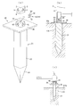
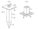
- (A) (b) and (c) is the front view which shows the state which installed the unit building provided with the pile foundation which concerns on this invention in the ground in a partial cross section, the expanded sectional view of a foundation part, and an exploded perspective view .
- (A) And (b) is a disassembled perspective view and sectional drawing for demonstrating the connection structure of a pile foundation and a column bottom part,
- (c) is explanatory drawing which shows the state which is striking to a pile foundation. is there.
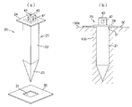
- (A) And (b) is an exploded perspective view showing composition of a pile foundation concerning other embodiments, and a sectional view showing the state where the ground was driven in. It is a perspective view which shows the deformation
- FIG. 1 It is sectional drawing which shows the other example of the connection structure of a pillar bottom part and a connection member.
- (A) And (b) is explanatory drawing which showed the state which protruded the rib for reinforcement on the lower surface of the earthing
- (A) And (b) is an exploded perspective view showing an example of composition of a unit house provided with a pile foundation concerning other embodiments of the present invention, it is a front view showing an installation state, and (c) relates to a modification It is structure explanatory drawing of a positioning base member.
- (A) And (b) is a figure which shows the other structural example of a positioning base member. It is explanatory drawing which shows the other structural example of a pile foundation.
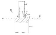
- (A) And (b) is a partial cross-section front view of the unit building provided with the pile foundation structure which concerns on other embodiment of this invention, and a principal part expanded sectional view.
- FIG.1 (a) (b) and (c) is the front view which shows the state which installed the unit building provided with the pile foundation which concerns on this invention in the ground in a partial cross section, the expanded sectional view of a foundation part, and a disassembled perspective view 2 (a) and 2 (b) are an exploded perspective view and a sectional view for explaining the connection structure between the pile foundation and the column bottom, and FIG. 2 (c) is a state in which the pile foundation is hit.
- the unit building 1 roughly includes a house unit 3 provided with pillars 5 made of steel square pipes at at least four corners, and a pile foundation 20 fixed to the bottom of each pillar 5 using fasteners 50 respectively. ing.
- the bottom of the pillar 5 and the pile foundation 20 constitute the foundation structure of the unit building of the present invention.
- the house unit 3 is constructed between hollow square pillars 5 erected at the four corners, an upper beam 6 constructed between the tops of the adjacent pillars 5, and a lower portion of the adjacent pillars 5 And a lower beam 7.
- a side plate is fixed to each side surface formed between each pillar 5, the upper beam 6 and the lower beam 7, and a bottom plate and a top plate are fixed to the bottom surface and the top surface, respectively.
- the pile portion 21 mainly receiving a load in the horizontal direction in the ground, and in the process of driving the pile portion 21 into the ground
- Grounding member 30 receives the load in the vertical direction by contacting the ground surface by determining the limit of the driving depth of the pile portion by contacting the ground surface 100a, and from the upper portion of the pile portion 21 or upward from the grounding member 30
- a connecting member 40 which is provided so as to protrude and is fixed to the bottom of each column 5 by a fastener 50.
- the grounding member 30, which is a rectangular flat plate, has its center lower surface integrated with the upper portion of the pile portion 21, and the coupling member 40 is fixed to the upper surface of the installation member 30 on the axial extension of the pile portion 21. It is done.
- the pile portion 21 efficiently receives and supports various stresses applied to the pile portion 21 from the pillar 5 via the connection member 40 by arranging the pile portion 21 and the connection member 40 in the same axial center shape.
- the pile foundation 20 is made of a metal material such as steel.
- the pile portion 21 includes a main body 22 having a quadrangular prism shape (which may have any cross-sectional shape such as another polygonal shape or a cylindrical shape or the like) and a pointed end 23 integrated with the tip of the main body 22.
- the width of one side of the pile portion 21 is about 30 mm, and the length is about 1 m.
- the ground contact member 30 is a flat member integrated with the upper end portion of the pile portion 21 by welding or the like, and the pile foundation 20 is ground more than necessary by the weight of the house unit 3 by contacting the ground surface 100a on the lower surface. It has an area sufficient to prevent it from being buried inside.
- the connecting member 40 is fixed to the upper surface of the grounding member 30 corresponding to the upper end portion of the pile portion 21.
- the upper surface of the connecting member is configured to be flat so as to easily support the flat bottom of the column 5.
- the connection hole 8 is formed on the bottom surface of the hollow square pillar-shaped column 5, and the connection hole 8 is connected to the upper surface of the hollow square pillar connection member 40 via the connection hole 8 and the fastening member 50. Is formed.
- a work opening 9 communicating with the connection hole 8 is formed in the lower peripheral wall of the column 5, and a work opening 42 communicating with the connection hole 41 is formed in the peripheral wall of the connection member 40.
- working openings 9 and 42 are formed in the four peripheral walls of the column 5 and the connecting member 40, respectively.
- the fastener 50 for example, a twist lock, a one-side bolt or the like is used.
- the connection hole 8 and the connection hole 41 are rectangular openings.
- the twist lock 51 is fixed to the shaft member 52, a fixed locking piece 53 fixed to one end of the shaft member and insertable into the connection hole 8 and the connected hole 41, and the other end of the shaft member.
- a movable locking piece 54 rotatably supported and insertable into the connection hole 8 and the connection hole 41.
- the fixed locking piece 53 is inserted into the connection hole 8 and the connected hole 41 in communication.
- the fixed locking piece 53 is detached from the connecting hole and the connected hole by rotating and locking the movable locking piece 54 by 90 degrees. Instead, the pillar and the connecting member are integrated.
- the fastening operation using the one-side bolt is also performed using the operation opening.
- the ground surface of the ground foundation 30 is in contact with the ground surface such that the lower surface of the ground contact member 30 contacts the ground surface corresponding to the bottoms of the four columns 5 of the house unit 3.
- the pile unit 21 is driven, and then the house unit 3 is transferred using a crane or the like so that the bottoms of the columns correspond to the upper surfaces of the connection members of the pile foundations 20 one by one. In this state, the bottoms of the columns and the connection members are integrally connected using the fasteners 50.
- the installation on the ground of unit building 1 is completed by such simple work.
- the pile foundation 20 is fixed to the bottom of each column 5, and in this state, the house unit is lowered to the ground surface to drive the pile portion 21 into the ground.
- the pile foundation 20 of the present invention since the pile portion 21 is relatively short such as about 1 m to 2 m, even non-experts can sufficiently drive them with a large hammer etc. Machines and expertise are not required.
- the connection member 40 may be directly hit, but as shown in FIG. It is preferable that the impact be transmitted to the pile portion 21 via the ground contact member 30.
- the pile portion 21 driven into the ground can sufficiently maintain the supporting force against the stress in the horizontal direction.
- the ground contact member 30 can disperse
- the type having the pillars 5 at the four corners is exemplified.
- the present invention is a house having five or more pillars. Needless to say, it can be applied to units.
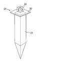
- Fig.3 (a) and (b) are the disassembled perspective view which shows the structure of the pile foundation which concerns on other embodiment, and sectional drawing which shows the state which the ground poured in.
- FIG. 3 the pile portion 21 and the connecting member 40 may be integrally manufactured in advance, and the ground member 30 may be fixed to the boundary between the pile portion and the connecting member by welding.
- a rectangular insertion hole 31 through which the main body 22 of the pile portion 21 can be inserted is formed in the central portion of the ground member 30, and the main body 22 of the pile portion is inserted into the insertion hole and integrated by welding.
- a locking projection (flange portion) 24 for positioning the grounding member 30 may be provided on the upper outer periphery of the pile portion to position the grounding member 30, and then welding may be performed.
- the grounding member 30 may be pressed against the ground surface 100 a by the weight of the house unit 3 without fixing the grounding member 30 to the locking projection 24 of the pile portion.
- the ground member 30 having a separate structure may be inserted into the pile portion on site. That is, the locking projection 24 for locking the grounding member is provided at an appropriate position on the upper outer periphery of the pile portion, and the grounding protrusion is formed by the locking projection 24 when the pile portion is inserted from the tip end into the insertion hole provided in the grounding member. Are configured to be locked. In this case, the ground contact member may or may not be fixed to the pile portion (the locking projection) by welding.
- the ground contact member In the case where the ground contact member is not fixed to the pile portion, it is detachable with respect to the pile portion, and the engagement projection 24 and the ground surface are obtained by driving the pile portion into the ground surface in a state inserted through the insertion hole 31 of the ground contact member. And hold the grounding member between them.
- the pile foundation can be divided into two parts and transported, so that the handling property is enhanced.
- the grounding member is not fixed to the pile portion by welding or the like, the welding operation can be omitted, and the manufacturing cost and the manufacturing cost can be reduced.
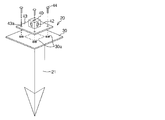
- FIG. 4 is a perspective view which shows the modification of the pile foundation of this invention.
- the pile foundation 20 is characterized in that the connecting member 40 is configured to be removable or displaceable with respect to the ground contact member 30.
- a fixed plate 43 protruding in a bowl shape from the outer periphery is integrated with the connecting member 40, and mounting holes 43a pass through at appropriate positions of the fixed plate 43, in this example, at four corners.
- a cross-shaped hole 30a is formed through at a position corresponding to each mounting hole 43a, and a bolt (for example, high tension bolt) 44 is inserted through the mounting hole 43a and the hole 30a
- the connecting member 40 can be fixed to the grounding member 30 by fastening according to the following.
- each connecting member is not aligned with the bottom of the column of the house unit after the pile 21 is driven into the ground surface, loosen the nut and extend along the cross hole 30a.
- the shape of the mounting hole 43a is not limited to a cross, and may be any shape as long as the position of the connecting member 40 can be adjusted in various directions.
- the mounting hole 43a, the bolt 44 and the nut constitute a position adjusting mechanism for adjusting the position of the connecting member.
- the above-described structure for finely adjusting the position of the connection member with respect to the ground contact member can also be applied to the relationship between the ground contact member and the connection member in the other embodiments.
- FIG. 5 is a cross-sectional view showing another example of the connection structure between the column bottom portion and the connecting member, and the connecting member 40 according to this example is a square pole whose upper surface is open.
- the lower part of the column 5 is dimensioned so that it can be fitted.
- Connection holes 9 and 43 communicating with each other are formed in the peripheral wall of the connection member and the peripheral wall of the lower portion of the column, and a fastener such as one side bolt 56 is inserted into both connection holes 9 and 43 Fix the The one-side bolt 56 has one end inserted into the connection holes 9 and 43 from the outside and then the other end is manipulated, whereby the expanded piece provided at the one end protrudes in the outer diameter direction and the connection hole 9 , 43 fixed so as not to fall off.
- a rib for reinforcing the ground contact member may be provided on the upper surface or the lower surface.
- 6 (a) and 6 (b) show a state in which the reinforcing rib 35 is provided on the lower surface of the grounding member 30, and by sharpening the tip of the rib 35 in a V shape, the anchor effect biting into the ground surface is obtained. The effect of preventing positional deviation in the horizontal direction can be expected.
- FIGS. 7A and 7B are an exploded perspective view showing a configuration example of a unit house provided with a pile foundation 20 according to another embodiment of the present invention, and a front view showing an installation state (c ) Is a configuration explanatory view of a positioning base member according to a modification.
- the unit building 1 according to the embodiment includes a box-like house unit 3 provided with pillars 5 at at least four corners, and a pile foundation 20 fixed to the bottom of each pillar 5 using fasteners 50 respectively. .
- the pile foundation 20 corresponds to the pile portion 21 driven into the ground, the connecting member 40 fixed to the upper portion of the pile portion 21 and fixed to the bottom of each pillar 5 by the fastener 50, and the bottom of each pillar
- a positioning base member (grounding member) 60 having a positioning hole 61 into which the pile portion 21 is inserted at a position, and a pile for restricting the insertion length of the pile portion when the pile portion is inserted into the positioning hole 61 of the positioning base member 60
- a locking projection (flange portion) 24 provided on the upper portion of the portion 21. And it is comprised so that the pile part of each pile foundation may be driven into a ground surface via each positioning hole 61 in the state which fixed the positioning base member 60 on the ground surface.
- the positioning base member 60 performs the function of supporting vertically downward load similar to the ground contact member 30 in the embodiment of FIG. If necessary, a reinforcing rib as shown in FIG. 6 may be provided on the upper surface or the lower surface of the positioning base member 60 in a protruding manner.
- the positioning base member 60 shown in FIGS. 7 (a) and 7 (b) is a square annular plate along the periphery of the bottom surface of the house unit 3, and a pile portion 21 is provided at a position corresponding to the bottom of each column 5 of the house unit.
- a positioning hole 61 is formed through for inserting the plug.
- the positioning base member 60 By using the positioning base member 60, the positioning base member 60 is fixed on the ground surface, and if the pile portion 21 is driven into the positioning hole 61, the positioning of the pile portion is completed. For this reason, the work which measures the position which strikes a pile in advance correctly using a tape measure etc. becomes unnecessary, and it becomes possible for a non-expert to carry out foundation work of house unit 3 extremely easily in a stricken area etc. In this case, the positioning base member 60 is assembled to the house unit 3 as a part of the pile foundation. In addition, even in the case where there is a step in the ground, the influence of the step on the house unit can be alleviated by fixing the flat positioning base on the ground surface.
- connection member 40 and the pile portion 21 provided with the locking projection 24 are driven into each positioning hole 61 of the positioning base member 60. It is possible to complete the installation of the pile foundation including the positioning member by driving the pile portion 21 into the ground when setting it on the ground surface.
- positioning member units in which connecting members and piles are fixed by welding on the upper and lower surfaces of the four corners of the positioning base member (grounding member) having no positioning hole are constructed in advance and transported to the site for use You may do it.
- the positioning base member 60 may be integrated with the locking projection 24 or the pile portion 21 by welding, but may not be integrated. Even if the positioning base member and the pile portion are not integrated, the positioning base member receives the load from the house in a state of being sandwiched between the locking projection 24 and the ground surface, so that it is vertically downward The ability to support the load can be well maintained.
- the positioning base member 60 may be disposed on the ground surface, and marks may be formed on the ground surface exposed from each positioning hole, and then the positioning base member may be removed before the pile foundation 20 (grounding according to the embodiment of FIG. It is also possible to drive into the ground portion marked (provided with the member 30).
- the positioning base member in this case is used merely as a means for aligning the pile foundation and is not incorporated as a part of the foundation. For this reason, it does not need to be metal and may be wooden or resin.
- the shape of the square annular positioning base member 60 is not limited to that shown in FIG. 7A, and various modifications are possible.
- projecting portions 63 may be provided at each corner portion of the inner periphery of the positioning base to secure a wide ground area around the portion where the pile portion 21 is driven.
- positioning base member 60 concerning this example is constituted as a square annular board, as shown in Drawing 8 (a), it is good also as non-annular board material which has an area which covers the whole bottom face of house unit 3, It may be a narrow plate material having a length corresponding to the lower part of two adjacent columns 5 as shown in FIG. Even if the positioning hole 61 is not provided in the positioning base member 60 of FIG. 8, the positioning base unit may be constructed by integrating the pile portion 21 and the connecting member 40 by welding at a portion corresponding to the lower portion of the column of the house unit. Good. In any case, by incorporating the positioning base member into the foundation of the house unit as a part of the pile foundation, it can be used as a wide-area grounding member.
- a foundation is constructed using the pile foundation 20 at a position corresponding to each pillar.
- the grounding member 30 or a part of the positioning base member 60 protrudes outward from the outer peripheral edge of the house unit 3, but the position of the connecting member 40 on the grounding member 30;
- the projection width of the grounding member 30 or the positioning base member from the outer periphery of the house unit may be reduced by variously adjusting the position of the positioning hole 61 on the positioning base member. Specifically, for example, as shown in FIG.
- the pile portion and the connecting member do not necessarily have to be arranged on the same axis.
- FIGS. 10 (a) and 10 (b) are a partial cross-sectional front view and a main part enlarged cross-sectional view of a unit building provided with a pile foundation structure according to another embodiment of the present invention.
- the same parts as in FIG. 1 will be described with the same reference numerals.
- the house unit 3 which comprises the unit building 1 which concerns on this embodiment is provided with the stud 70 between adjacent pillars separately from the pillar 5 which consists of steel square pipes provided in the four corners.
- the stud 70 is disposed straddling between the upper beam 6 and the lower beam 7 which face each other in the vertical positional relationship.
- the pile foundation 20 shown in FIG. 1 or the like can be applied.
- the unit building 1 has pillars 5 provided at at least four corners, lower beams 7 connecting between lower portions of adjacent columns, and studs 70 disposed between adjacent pillars 5 and fixed to lower beams at lower portions.
- the pile foundation 20 including the house unit 3 and the pile foundation 20 for supporting the bottom of each pillar 5 and the stud 70, the pile foundation 20 for supporting the stud is a pile in which at least a part including the tip is driven into the ground.
- Grounding member 30 which determines the limit of the driving depth of the pile portion by contacting the ground portion in the process of driving the portion 21 and the pile portion into the ground, and projecting upward from the upper portion of the pile portion or the ground member
- the pile portion 21 mainly receiving a load in the horizontal direction in the ground, and in the process of driving the pile portion 21 into the ground
- Grounding member 30 receives the load in the vertical direction by contacting the ground surface by determining the limit of the driving depth of the pile portion by contacting the ground surface 100a, and from the upper portion of the pile portion 21 or upward from the grounding member 30
- a connecting member 40 provided in a protruding manner.
- the lower part of the stud 70 is fixed to the upper surface of the lower beam 7 by a bolt or the like, while the upper part of the pile foundation 20 is fixed to the lower surface of the lower beam 7 by a bolt or the like.
- the foundation 20 is connected. That is, when manufacturing the unit house 3 in a factory, the connecting plate 71 is integrated in advance in the form of a flange on the lower surface of the stud 70 by welding or the like, and the connecting plate 71 is bolted to the upper surface of the lower beam or Fix it.
- the pile foundation 20 the one according to the embodiment of FIG. 1 is used, and the connecting plate 73 is integrated in a flange shape by welding or the like on the upper surface of the connecting member 40 at the top of the pile foundation 20 in a factory.
- the work of fixing the connecting plate 73 of the pile foundation 20 with a bolt or the like on the lower surface of the lower beam 7 located immediately below the stud is performed to complete the assembly of the pile foundation to the stud.
- a reinforcing member 7a for reinforcing the lower beam is fixed to the lower beam 7 in contact with the lower portion of the stud 70, if necessary.
- the pile part 21 which comprises the pile foundation assembled
- attached to a stud the type shown in FIG.3, FIG.6, FIG.9 other than what concerns on embodiment of FIG. 1 is also contained.
- the positioning base member may be shared as a grounding member for the stud. That is, by forming the positioning holes into which the pile portions for the pillars are inserted between the positioning holes 61 of the positioning base member 6, the positioning base can be shared with the pile portions for the pillars.
- the unit building provided with the pile foundation according to the present invention uses a pile foundation having a simple structure with a short pile portion (for example, 1 m to 2 m) in foundation work to fix the lower part of the column of house unit to the ground. It is convenient for transportation, and it is relatively easy to set up a house unit on the ground in a short period of time, even under circumstances where sufficient heavy equipment, equipment and specialized workers can not be secured as in the disaster area can do.
- the ground contact member In the pile foundation, when the pile portion is driven into the ground surface, the ground contact member contacts the ground surface to support the vertically downward load, so that the house unit can be prevented from sinking in the ground, and the pile portion is horizontal Can support the load. It can be applied regardless of the hardness of the ground by the supporting force against the horizontal load by the pile portion and the supporting force of the vertical load by the grounding member. Even if the hardness of the ground is a small value such as an N value of 3, for example, sufficient durability as a foundation can be ensured. In the case of applying to a ground having an N value of about 3, the ground contact member is, for example, a square of 1.5 m square.
- the length of the pile is set to around 1m or 2m
- the area of the ground contact member is the cross section of the pile and the hardness of the ground
- the weight of the house unit etc. Determined in relation to The ground may not have sufficient strength as a place to set up a temporary housing in a disaster-affected area such as an earthquake-affected area, and the construction of the base was difficult with the conventional method, but the basic structure of the present invention is adopted Therefore, even soft ground can be installed. It will not fall over due to the sinking of the house unit to the ground or the overturning moment acting on the foundation.
- by reducing the base weight and simplifying the structure of the base construction becomes easier.
- the fixed position of the pile member with respect to the ground contact member may not be the position corresponding to the central portion of the ground contact member. Moreover, the position of a pile member and a connection member may be shifted. Since the positioning base can ensure a large ground contact area, the area supporting the vertical load can be enlarged to improve the installation stability of the house unit. Moreover, it becomes possible to install a house unit stably corresponding to the level
- Reference numeral 22 main body, 23: pointed end, 24: locking projection, 30: grounding member, 31: insertion hole, 35: reinforcing rib, 40: coupling member, 41: coupling hole, 42: opening for operation Parts, 43: fixed plate, 43a: hole, 44: bolt, 45: impact cover, 50: fastening member, 51: twist lock, 52: shaft member, 53: fixed locking piece, 54: movable locking piece , 56: one side bolt, 60: positioning base member, 61: positioning hole, 70: stud, 71, 73: connection plate, 100: ground, 100a: ground surface.
Landscapes
- Engineering & Computer Science (AREA)
- Civil Engineering (AREA)
- Structural Engineering (AREA)
- Architecture (AREA)
- Life Sciences & Earth Sciences (AREA)
- General Life Sciences & Earth Sciences (AREA)
- Mining & Mineral Resources (AREA)
- Paleontology (AREA)
- General Engineering & Computer Science (AREA)
- Physics & Mathematics (AREA)
- Electromagnetism (AREA)
- Foundations (AREA)
Applications Claiming Priority (2)
| Application Number | Priority Date | Filing Date | Title |
|---|---|---|---|
| JP2010-187504 | 2010-08-24 | ||
| JP2010187504A JP5567938B2 (ja) | 2010-08-24 | 2010-08-24 | 家屋ユニットの杭基礎 |
Publications (1)
| Publication Number | Publication Date |
|---|---|
| WO2012026345A1 true WO2012026345A1 (ja) | 2012-03-01 |
Family
ID=45723348
Family Applications (1)
| Application Number | Title | Priority Date | Filing Date |
|---|---|---|---|
| PCT/JP2011/068416 Ceased WO2012026345A1 (ja) | 2010-08-24 | 2011-08-12 | 家屋ユニットの杭基礎 |
Country Status (2)
| Country | Link |
|---|---|
| JP (1) | JP5567938B2 (enExample) |
| WO (1) | WO2012026345A1 (enExample) |
Cited By (10)
| Publication number | Priority date | Publication date | Assignee | Title |
|---|---|---|---|---|
| EP2864011A4 (en) * | 2012-06-26 | 2016-04-06 | Outotec Finland Oy | SOLVENT EXTRACTION BASES WITH A FOUNDATION |
| US9631254B2 (en) | 2012-06-26 | 2017-04-25 | Outotec (Finland) Oy | Solvent extraction method and solvent extraction settler |
| US9731222B2 (en) | 2012-06-26 | 2017-08-15 | Outotec (Finland) Oy | Solvent extraction settler arrangement |
| US9770847B2 (en) | 2012-06-26 | 2017-09-26 | Outotec (Finland) Oy | Method of manufacturing a separation fence and separation fence |
| US9863017B2 (en) | 2012-06-26 | 2018-01-09 | Outotec (Finland) Oy | Solvent extraction settler arrangement |
| US10220331B2 (en) | 2012-06-26 | 2019-03-05 | Outotec (Finland) Oy | Method of manufacturing a solvent extraction settler and solvent extraction settler |
| US10661199B2 (en) | 2012-06-26 | 2020-05-26 | Outotec (Finland) Oy | Method of manufacturing a launder and launder |
| WO2020236048A1 (en) * | 2019-05-22 | 2020-11-26 | Inventhor Sweden Ab | Container support system for strengthening ground surfaces for container handling |
| CN114135139A (zh) * | 2021-12-02 | 2022-03-04 | 黄栋 | 用于历史街区地下空间开发中既有建筑物原位保护装置 |
| CN116201160A (zh) * | 2023-01-06 | 2023-06-02 | 华锦建设集团股份有限公司 | 房屋建筑桩基结构及施工方法 |
Families Citing this family (3)
| Publication number | Priority date | Publication date | Assignee | Title |
|---|---|---|---|---|
| JP6614454B2 (ja) * | 2016-10-20 | 2019-12-04 | 公益財団法人鉄道総合技術研究所 | 構造物の支持構造 |
| US11168896B2 (en) * | 2017-08-08 | 2021-11-09 | Intex Holdings Pty Ltd | Temperature control of a modular building |
| JP6959162B2 (ja) * | 2018-02-09 | 2021-11-02 | 俊也 鈴木 | 移動可能なコンテナコインランドリー |
Citations (4)
| Publication number | Priority date | Publication date | Assignee | Title |
|---|---|---|---|---|
| JPH1193273A (ja) * | 1997-09-24 | 1999-04-06 | Sekisui Chem Co Ltd | ユニット建物 |
| JP2001059221A (ja) * | 1999-08-23 | 2001-03-06 | Asahi Tec Corp | 地中アンカ |
| JP2003184184A (ja) * | 2001-12-21 | 2003-07-03 | Komatsu House Ltd | 建物ユニットの接合構造および接合方法 |
| JP3140159U (ja) * | 2007-12-26 | 2008-03-13 | 三協フロンテア株式会社 | ユニットハウス用鉄骨基礎 |
Family Cites Families (6)
| Publication number | Priority date | Publication date | Assignee | Title |
|---|---|---|---|---|
| JPS6319660U (enExample) * | 1986-07-22 | 1988-02-09 | ||
| JPH03260223A (ja) * | 1990-03-09 | 1991-11-20 | Misawa Homes Co Ltd | 住宅の基礎構築用位置決めプレート |
| JPH04343984A (ja) * | 1991-05-21 | 1992-11-30 | Misawa Homes Co Ltd | 小屋梁設置装置 |
| JP4111601B2 (ja) * | 1998-09-08 | 2008-07-02 | 常郎 後藤 | アンカー |
| US20040103599A1 (en) * | 2001-02-02 | 2004-06-03 | Arthur Keck | Ground anchor |
| JP2009041285A (ja) * | 2007-08-09 | 2009-02-26 | Toshihiro Hiraoka | カーポート屋根支持柱固定装置 |
-
2010
- 2010-08-24 JP JP2010187504A patent/JP5567938B2/ja not_active Expired - Fee Related
-
2011
- 2011-08-12 WO PCT/JP2011/068416 patent/WO2012026345A1/ja not_active Ceased
Patent Citations (4)
| Publication number | Priority date | Publication date | Assignee | Title |
|---|---|---|---|---|
| JPH1193273A (ja) * | 1997-09-24 | 1999-04-06 | Sekisui Chem Co Ltd | ユニット建物 |
| JP2001059221A (ja) * | 1999-08-23 | 2001-03-06 | Asahi Tec Corp | 地中アンカ |
| JP2003184184A (ja) * | 2001-12-21 | 2003-07-03 | Komatsu House Ltd | 建物ユニットの接合構造および接合方法 |
| JP3140159U (ja) * | 2007-12-26 | 2008-03-13 | 三協フロンテア株式会社 | ユニットハウス用鉄骨基礎 |
Cited By (13)
| Publication number | Priority date | Publication date | Assignee | Title |
|---|---|---|---|---|
| US10661199B2 (en) | 2012-06-26 | 2020-05-26 | Outotec (Finland) Oy | Method of manufacturing a launder and launder |
| US9631254B2 (en) | 2012-06-26 | 2017-04-25 | Outotec (Finland) Oy | Solvent extraction method and solvent extraction settler |
| US9731222B2 (en) | 2012-06-26 | 2017-08-15 | Outotec (Finland) Oy | Solvent extraction settler arrangement |
| US9770847B2 (en) | 2012-06-26 | 2017-09-26 | Outotec (Finland) Oy | Method of manufacturing a separation fence and separation fence |
| US9863017B2 (en) | 2012-06-26 | 2018-01-09 | Outotec (Finland) Oy | Solvent extraction settler arrangement |
| US10220331B2 (en) | 2012-06-26 | 2019-03-05 | Outotec (Finland) Oy | Method of manufacturing a solvent extraction settler and solvent extraction settler |
| EP2864011A4 (en) * | 2012-06-26 | 2016-04-06 | Outotec Finland Oy | SOLVENT EXTRACTION BASES WITH A FOUNDATION |
| WO2020236048A1 (en) * | 2019-05-22 | 2020-11-26 | Inventhor Sweden Ab | Container support system for strengthening ground surfaces for container handling |
| SE544082C2 (sv) * | 2019-05-22 | 2021-12-14 | Inventhor Sweden Ab | Containerstödssystem för förstärkning av markytor för containerhantering samt metod för att montera ett sådant system |
| EP3973108A4 (en) * | 2019-05-22 | 2023-07-12 | Inventhor Sweden AB | CONTAINER SUPPORT SYSTEM TO REINFORCE FLOOR SURFACES FOR CONTAINER HANDLING |
| CN114135139A (zh) * | 2021-12-02 | 2022-03-04 | 黄栋 | 用于历史街区地下空间开发中既有建筑物原位保护装置 |
| CN116201160A (zh) * | 2023-01-06 | 2023-06-02 | 华锦建设集团股份有限公司 | 房屋建筑桩基结构及施工方法 |
| CN116201160B (zh) * | 2023-01-06 | 2023-08-15 | 华锦建设集团股份有限公司 | 房屋建筑桩基结构及施工方法 |
Also Published As
| Publication number | Publication date |
|---|---|
| JP2012046897A (ja) | 2012-03-08 |
| JP5567938B2 (ja) | 2014-08-06 |
Similar Documents
| Publication | Publication Date | Title |
|---|---|---|
| WO2012026345A1 (ja) | 家屋ユニットの杭基礎 | |
| JP2012046897A5 (enExample) | ||
| JP5131518B2 (ja) | 鋼管杭と鉄骨柱の接合構造 | |
| JP2014005652A (ja) | 杭式桟橋の施工方法 | |
| JP2019019621A (ja) | 柱固定金具 | |
| KR20050006598A (ko) | 건축물의 기초 기둥 구축용 조립식 콘크리트 거푸집 | |
| JP2013040486A (ja) | 既存組立柱の柱脚部の補強方法および既存組立柱の柱脚部の補強構造 | |
| JP2014077319A (ja) | 太陽光パネル架台および太陽光パネル架台の施工方法 | |
| JP4612422B2 (ja) | 構造物の施工方法とこれに使用される基礎構造 | |
| JP4446544B2 (ja) | 住宅の基礎構造 | |
| KR101759549B1 (ko) | 말뚝을 이용한 데크용 기둥 기초 | |
| JP4628838B2 (ja) | 鋼製基礎構造 | |
| JP4614159B2 (ja) | 鋼管杭と鉄骨柱の接合構造および接合方法 | |
| JP6045201B2 (ja) | 梁接合部構造および耐力パネル構造 | |
| JP5203059B2 (ja) | コンクリート杭と鋼杭の接続構造 | |
| JP2011246872A (ja) | 建築物設置具 | |
| JP2019031815A (ja) | 構造物耐震補強構造 | |
| JP2001262592A (ja) | 構築物の基礎及びその施工方法 | |
| JPH0371537B2 (enExample) | ||
| JP2876182B2 (ja) | 仮設シャッター用ジョイント基礎 | |
| JP2005139635A (ja) | 土留支保工法とその枠体構造 | |
| JP3215616U (ja) | 木造建築物の狭小壁 | |
| AU2012211452B2 (en) | Joint structure of column and steel pipe pile | |
| JP5138739B2 (ja) | 建物ユニットの連結構造及び連結構造の施工方法 | |
| JP2008255713A (ja) | 木造建築物及び木造建築物の耐震補強方法 |
Legal Events
| Date | Code | Title | Description |
|---|---|---|---|
| 121 | Ep: the epo has been informed by wipo that ep was designated in this application |
Ref document number: 11819809 Country of ref document: EP Kind code of ref document: A1 |
|
| NENP | Non-entry into the national phase |
Ref country code: DE |
|
| 32PN | Ep: public notification in the ep bulletin as address of the adressee cannot be established |
Free format text: NOTING OF LOSS OF RIGHTS PURSUANT TO RULE 112(1) EPC (EPO FORM 1205A DATED 13-06-2013) |
|
| 122 | Ep: pct application non-entry in european phase |
Ref document number: 11819809 Country of ref document: EP Kind code of ref document: A1 |