WO2012026345A1 - Pile foundation for house unit - Google Patents
Pile foundation for house unit Download PDFInfo
- Publication number
- WO2012026345A1 WO2012026345A1 PCT/JP2011/068416 JP2011068416W WO2012026345A1 WO 2012026345 A1 WO2012026345 A1 WO 2012026345A1 JP 2011068416 W JP2011068416 W JP 2011068416W WO 2012026345 A1 WO2012026345 A1 WO 2012026345A1
- Authority
- WO
- WIPO (PCT)
- Prior art keywords
- pile
- ground
- house unit
- pile foundation
- fixed
- Prior art date
Links
Images


Classifications
-
- E—FIXED CONSTRUCTIONS
- E04—BUILDING
- E04B—GENERAL BUILDING CONSTRUCTIONS; WALLS, e.g. PARTITIONS; ROOFS; FLOORS; CEILINGS; INSULATION OR OTHER PROTECTION OF BUILDINGS
- E04B1/00—Constructions in general; Structures which are not restricted either to walls, e.g. partitions, or floors or ceilings or roofs
- E04B1/348—Structures composed of units comprising at least considerable parts of two sides of a room, e.g. box-like or cell-like units closed or in skeleton form
- E04B1/34815—Elements not integrated in a skeleton
- E04B1/3483—Elements not integrated in a skeleton the supporting structure consisting of metal
-
- E—FIXED CONSTRUCTIONS
- E02—HYDRAULIC ENGINEERING; FOUNDATIONS; SOIL SHIFTING
- E02D—FOUNDATIONS; EXCAVATIONS; EMBANKMENTS; UNDERGROUND OR UNDERWATER STRUCTURES
- E02D27/00—Foundations as substructures
- E02D27/10—Deep foundations
- E02D27/12—Pile foundations
- E02D27/14—Pile framings, i.e. piles assembled to form the substructure
Abstract
Provided is a pile foundation for a house unit, the pile foundation enabling, when constructing a temporary house in a disaster stricken area, etc. using a prefabricated building, foundations having necessary and sufficient strength to be installed on the ground surface by simple work by a non-expert without the use of large-sized heavy construction equipment and base materials. A prefabricated building (1) is provided with: a house unit (3) having supports (5) at at least four corners thereof; and pile foundations (20) respectively supporting the bottoms of the supports. The pile foundations each comprise: a pile section (21) configured in such a manner that at least a part thereof, which includes the tip thereof, is adapted to be driven into the ground (100); a ground contact member (30) for determining the limit of the driving depth of the pile section by making contact with the ground surface in the process in which the pile section is driven into the ground; and a connection member (40) protruding upward from the upper part of the pile section or from the ground contact member and affixed to the bottom of the support.
Description
本発明は、ユニット建物の四隅に位置する柱の底部を地盤に固定するための技術に関し、例えば被災地等において仮設住居用等として利用されるユニット建物を比較的軟弱な地盤面に固定する場合においても垂直方向及び水平方向への支持強度を十分に確保して設置安定性を高めることができる家屋ユニットの杭基礎に関する。
The present invention relates to a technique for fixing the bottom of a column located at four corners of a unit building to the ground, for example, when fixing a unit building used for temporary housing etc. in a disaster area etc. to a relatively soft ground surface The present invention also relates to a pile foundation of a house unit capable of securing sufficient vertical and horizontal support strength and enhancing installation stability.
ユニット建物は、工場で製造されてから設置現場に運送され、現場で比較的簡易に設置、組立てできるため、住居、事務所、店舗、倉庫等として多用されている。
特に、箱形に形成されたユニット建物は、4本の柱と上下の梁から成る軸組に対して、底板、天井板、側壁等を組み付けた単純構造を備えており、高耐久性、設置移設の容易性、低コスト、加工、内装及び外装の容易性、ユニット建物間の組付けの容易性等、種々の利点を有している(特許文献1、2、3、4)。
ところで、従来のユニット建物を地震の被災地等に仮設住居用として設置する場合には、基礎工事に際して、地盤の掘削工事、地盤改良、コンクリート基礎の形成、数m~30m程度の長尺な杭の打ち込みが必要となるため、大型、高重量の重機類、基材や、熟練した作業員が必要となり、工期の長期化やコストアップの原因となる。
仮に、強度、耐久性を犠牲にした簡易、且つ低コストな基礎工事で間に合わせた場合には、余震や風雨に対するユニット建物の設置安定性を確保することが難しくなる。特に、被災地では、十分な人数の熟練した作業人員を確保できず、素人が設置作業に従事することも多々あるため、簡単な道具を用いた素人によっても構築できる十分な強度を有した基礎が必要となる。 The unit building is manufactured at the factory and transported to the installation site, and can be installed and assembled relatively easily at the site, so it is often used as a residence, office, shop, warehouse, etc.
In particular, the unit building formed in a box shape has a simple structure in which a base plate, a ceiling plate, a side wall, etc. are assembled to a shaft set consisting of four columns and upper and lower beams, high durability, installation It has various advantages such as ease of relocation, low cost, ease of processing, interior and exterior, and ease of assembly between unit buildings ( Patent Documents 1, 2, 3, 4).
By the way, when installing a conventional unit building for temporary housing in a disaster affected area etc. of earthquake, excavating work of ground, improvement of ground, formation of concrete foundation, long pile of about several meters to 30 meters at the time of foundation work In addition, large and heavy heavy machinery, a base material, and skilled workers are required, which causes the construction period to be prolonged and cost increase.
If a simple and low-cost foundation work is made at the expense of strength and durability, it will be difficult to ensure the installation stability of the unit building against aftershocks and wind and rain. In particular, in a disaster-stricken area, a sufficient number of skilled work personnel can not be secured, and there are many cases where an layman is engaged in installation work, so a foundation with sufficient strength that can be constructed by laymen using simple tools. Is required.
特に、箱形に形成されたユニット建物は、4本の柱と上下の梁から成る軸組に対して、底板、天井板、側壁等を組み付けた単純構造を備えており、高耐久性、設置移設の容易性、低コスト、加工、内装及び外装の容易性、ユニット建物間の組付けの容易性等、種々の利点を有している(特許文献1、2、3、4)。
ところで、従来のユニット建物を地震の被災地等に仮設住居用として設置する場合には、基礎工事に際して、地盤の掘削工事、地盤改良、コンクリート基礎の形成、数m~30m程度の長尺な杭の打ち込みが必要となるため、大型、高重量の重機類、基材や、熟練した作業員が必要となり、工期の長期化やコストアップの原因となる。
仮に、強度、耐久性を犠牲にした簡易、且つ低コストな基礎工事で間に合わせた場合には、余震や風雨に対するユニット建物の設置安定性を確保することが難しくなる。特に、被災地では、十分な人数の熟練した作業人員を確保できず、素人が設置作業に従事することも多々あるため、簡単な道具を用いた素人によっても構築できる十分な強度を有した基礎が必要となる。 The unit building is manufactured at the factory and transported to the installation site, and can be installed and assembled relatively easily at the site, so it is often used as a residence, office, shop, warehouse, etc.
In particular, the unit building formed in a box shape has a simple structure in which a base plate, a ceiling plate, a side wall, etc. are assembled to a shaft set consisting of four columns and upper and lower beams, high durability, installation It has various advantages such as ease of relocation, low cost, ease of processing, interior and exterior, and ease of assembly between unit buildings (
By the way, when installing a conventional unit building for temporary housing in a disaster affected area etc. of earthquake, excavating work of ground, improvement of ground, formation of concrete foundation, long pile of about several meters to 30 meters at the time of foundation work In addition, large and heavy heavy machinery, a base material, and skilled workers are required, which causes the construction period to be prolonged and cost increase.
If a simple and low-cost foundation work is made at the expense of strength and durability, it will be difficult to ensure the installation stability of the unit building against aftershocks and wind and rain. In particular, in a disaster-stricken area, a sufficient number of skilled work personnel can not be secured, and there are many cases where an layman is engaged in installation work, so a foundation with sufficient strength that can be constructed by laymen using simple tools. Is required.
被災地等においてユニット建物によって仮設住居を構築する場合に、基礎工事に地盤の掘削、地盤改良、コンクリート基礎の形成、長尺な杭の打ち込み等が必要となるとすれば、迅速な被災者救済活動が困難となることが明かである。一方、強度、耐久性を犠牲にした簡易、且つ低コストな基礎工事で間に合わせた場合には、ユニット建物の設置安定性を確保することが難しくなる。
本発明は上記に鑑みてなされたものであり、被災地等においてユニット建物によって仮設住宅を構築する場合に、大型、高重量の重機類、基材を使用せずに、非専門技術者による簡易な作業によって、地盤面に必要十分な強度を備えた基礎を設置することができる家屋ユニットの杭基礎を提供することを目的としている。 When building temporary housing with unit buildings in a disaster area etc., if it is necessary to excavate the ground, improve the ground, form a concrete foundation, drive a long pile, etc., for foundation work, we will promptly provide relief for victims. It is clear that On the other hand, in the case of simple and low-cost foundation work at the expense of strength and durability, it becomes difficult to ensure the installation stability of the unit building.
The present invention has been made in view of the above, and when constructing a temporary housing by a unit building in a disaster area or the like, a large-sized, heavy heavy machine, a simple by a non-specialist technician without using a base material Purpose is to provide a pile foundation of house units that can install a foundation with sufficient strength on the ground surface.
上記目的を達成するため、請求項1の発明は、少なくとも四隅に柱を備えた家屋ユニットの前記各柱の底部を夫々支持する杭基礎であって、先部を含む少なくとも一部が地盤内に打ち込まれる杭部と、該杭部が地盤内に打ち込まれる過程で地盤面と接することにより該杭部の打ち込み深さの限界を定める接地部材と、前記杭部の上部、或いは該接地部材から上方へ突設されて前記各柱の底部に対して固定される連結部材と、を備えていることを特徴とする。
請求項2の発明では、前記接地部材は、前記杭部に対して固定、又は非固定であることを特徴とする。
請求項3の発明では、前記各柱の少なくとも下部は中空であり、その底面には連結穴が形成され、且つその周壁には夫々前記連結穴と連通する作業用開口部が形成されており、前記連結部材は中空であり、その上面には前記連結穴と連結される被連結穴が形成され、且つその周壁には夫々前記被連結穴と連通する作業用開口部が形成されていることを特徴とする。 In order to achieve the above object, the invention according to claim 1 is a pile foundation for supporting the bottom of each pillar of a house unit having pillars at least at four corners, and at least a part including the tip is in the ground A pile portion to be driven, a ground contact member which defines a limit of a driving depth of the pile portion by contacting the ground surface in the process of driving the pile portion into the ground, an upper portion of the pile portion or an upper side from the ground member And a connecting member fixed to the bottom of each of the columns.
The invention according toclaim 2 is characterized in that the ground contact member is fixed or not fixed to the pile portion.
In the invention ofclaim 3, at least a lower portion of each of the pillars is hollow, a connection hole is formed in the bottom surface, and a work opening communicating with the connection hole is formed in the peripheral wall, respectively. The connecting member is hollow, and a connecting hole to be connected to the connecting hole is formed on the upper surface, and a working opening communicating with the connecting hole is formed on the peripheral wall, respectively. It features.
請求項2の発明では、前記接地部材は、前記杭部に対して固定、又は非固定であることを特徴とする。
請求項3の発明では、前記各柱の少なくとも下部は中空であり、その底面には連結穴が形成され、且つその周壁には夫々前記連結穴と連通する作業用開口部が形成されており、前記連結部材は中空であり、その上面には前記連結穴と連結される被連結穴が形成され、且つその周壁には夫々前記被連結穴と連通する作業用開口部が形成されていることを特徴とする。 In order to achieve the above object, the invention according to claim 1 is a pile foundation for supporting the bottom of each pillar of a house unit having pillars at least at four corners, and at least a part including the tip is in the ground A pile portion to be driven, a ground contact member which defines a limit of a driving depth of the pile portion by contacting the ground surface in the process of driving the pile portion into the ground, an upper portion of the pile portion or an upper side from the ground member And a connecting member fixed to the bottom of each of the columns.
The invention according to
In the invention of
請求項4の発明は、少なくとも四隅に柱を備えた家屋ユニットの前記各柱の底部を夫々支持する杭基礎であって、先部を含む少なくとも一部が地盤に打ち込まれる杭部と、該杭部の上部に固定されて各柱の底部に対して固定される連結部材と、前記各柱の底部と対応する位置に杭部を差し込む位置決め穴を有した位置決めベース部材と、前記杭部が位置決めベース部材の位置決め穴に差し込まれた時に杭部の差込み長を規制するために該杭部の上部に設けられた係止突起と、を備えたことを特徴とする。
請求項5の発明では、前記位置決めベース部材は、前記杭部に対して固定、又は非固定であることを特徴とする。
請求項6の発明では、前記位置決めベース部材は、環状の板材であることを特徴とする。 The invention according to claim 4 is a pile foundation for supporting the bottom of each of the columns of the house unit having columns at least at four corners, the pile including at least a portion including the tip being driven into the ground, and the pile Member fixed to the top of the column and fixed to the bottom of each column, a positioning base member having a positioning hole for inserting the pile into a position corresponding to the bottom of each column, and the pile being positioned And a locking projection provided on an upper portion of the pile portion in order to restrict the insertion length of the pile portion when inserted into the positioning hole of the base member.
The invention according toclaim 5 is characterized in that the positioning base member is fixed or not fixed to the pile portion.
In the invention ofclaim 6, the positioning base member is an annular plate material.
請求項5の発明では、前記位置決めベース部材は、前記杭部に対して固定、又は非固定であることを特徴とする。
請求項6の発明では、前記位置決めベース部材は、環状の板材であることを特徴とする。 The invention according to claim 4 is a pile foundation for supporting the bottom of each of the columns of the house unit having columns at least at four corners, the pile including at least a portion including the tip being driven into the ground, and the pile Member fixed to the top of the column and fixed to the bottom of each column, a positioning base member having a positioning hole for inserting the pile into a position corresponding to the bottom of each column, and the pile being positioned And a locking projection provided on an upper portion of the pile portion in order to restrict the insertion length of the pile portion when inserted into the positioning hole of the base member.
The invention according to
In the invention of
請求項7の発明では、前記接地部材、又は前記位置決めベース部材の上面、又は/及び、底面に補強用のリブが突設されていることを特徴とする。
請求項8の発明では、前記接地部材、或いは前記位置決めベース部材に対する前記連結部材の位置を調整する位置調整機構を備えたことを特徴とする。
請求項9の発明では、前記杭部と前記連結部材は同一軸線上、又は非同一軸線上に配置されていることを特徴とする。
請求項10の発明は、少なくとも四隅に設けた柱、隣接する前記柱の下部間を連結する下梁、及び隣接する前記柱間に配置されて下部を前記下梁に固定された間柱を有した家屋ユニットの前記各柱、及び前記間柱の底部を夫々支持する杭基礎であって、前記間柱を支持する前記杭基礎は、先部を含む少なくとも一部が地盤内に打ち込まれる杭部と、該杭部が地盤内に打ち込まれる過程で地盤面と接することにより該杭部の打ち込み深さの限界を定める接地部材と、前記杭部の上部、或いは該接地部材から上方へ突設されて前記間柱の下部と対応する前記下梁の底部に対して固定される連結部材と、を備えていることを特徴とする。 The invention according toclaim 7 is characterized in that a reinforcing rib is protruded from the upper surface or / and the lower surface of the grounding member or the positioning base member.
The invention according toclaim 8 is characterized in that it comprises a position adjusting mechanism for adjusting the position of the connecting member with respect to the grounding member or the positioning base member.
The invention according toclaim 9 is characterized in that the pile portion and the connection member are disposed on the same axis or on a non-coaxial line.
The invention according to claim 10 includes a column provided at at least four corners, a lower beam connecting between lower portions of adjacent columns, and a stud disposed between the adjacent columns and fixed at the lower portion to the lower beam. It is a pile foundation which respectively supports the above-mentioned each pillar of a house unit, and the bottom of the above-mentioned pillar, and the above-mentioned pile foundation which supports the above-mentioned pillar is a pile part by which at least one copy including the tip is driven into the ground. A ground contact member which limits the driving depth of the pile portion by coming into contact with the ground surface in the process of driving the pile portion into the ground, the upper portion of the pile portion or the projection projecting upward from the ground member And a connecting member fixed to a lower portion of the lower beam corresponding to the lower portion of the lower beam.
請求項8の発明では、前記接地部材、或いは前記位置決めベース部材に対する前記連結部材の位置を調整する位置調整機構を備えたことを特徴とする。
請求項9の発明では、前記杭部と前記連結部材は同一軸線上、又は非同一軸線上に配置されていることを特徴とする。
請求項10の発明は、少なくとも四隅に設けた柱、隣接する前記柱の下部間を連結する下梁、及び隣接する前記柱間に配置されて下部を前記下梁に固定された間柱を有した家屋ユニットの前記各柱、及び前記間柱の底部を夫々支持する杭基礎であって、前記間柱を支持する前記杭基礎は、先部を含む少なくとも一部が地盤内に打ち込まれる杭部と、該杭部が地盤内に打ち込まれる過程で地盤面と接することにより該杭部の打ち込み深さの限界を定める接地部材と、前記杭部の上部、或いは該接地部材から上方へ突設されて前記間柱の下部と対応する前記下梁の底部に対して固定される連結部材と、を備えていることを特徴とする。 The invention according to
The invention according to
The invention according to
The invention according to claim 10 includes a column provided at at least four corners, a lower beam connecting between lower portions of adjacent columns, and a stud disposed between the adjacent columns and fixed at the lower portion to the lower beam. It is a pile foundation which respectively supports the above-mentioned each pillar of a house unit, and the bottom of the above-mentioned pillar, and the above-mentioned pile foundation which supports the above-mentioned pillar is a pile part by which at least one copy including the tip is driven into the ground. A ground contact member which limits the driving depth of the pile portion by coming into contact with the ground surface in the process of driving the pile portion into the ground, the upper portion of the pile portion or the projection projecting upward from the ground member And a connecting member fixed to a lower portion of the lower beam corresponding to the lower portion of the lower beam.
以上のように本発明によれば、家屋ユニットの柱の下部を地盤に固定する基礎工事において、杭部が短尺な簡易構造の杭基礎を使用しているので、運搬に便利であり、被災地等のように十分な重機、機材、専門の作業員を確保することができない状況下においても、比較的容易、且つ短期間に家屋ユニットを地盤に設置することができる。
杭基礎は、杭部を地盤面に打ち込んだときに接地部材が地盤面と接して垂直下向きの荷重を支持するため、家屋ユニットが地盤内に陥没することを防止でき、また杭部が水平方向への荷重を支持することができる。
また、接地部材上における連結部材の固定位置を変更可能に構成することにより、杭部を地盤に打ち込んだ後で、家屋ユニットの柱と連結部材との位置ずれによる不具合(杭部の打ち込み位置の微修正作業)をなくすことができる。
接地部材の上面、或いは下面に補強用のリブを設けても良い。接地部材の下面に設けたリブはアンカー効果を発揮することができる。 As described above, according to the present invention, in the foundation work for fixing the lower part of the column of the house unit to the ground, the pile part uses the short pile foundation with a simple structure, which is convenient for transportation, Even in a situation where sufficient heavy machinery, equipment, and specialized workers can not be secured, such as, etc., the house unit can be installed on the ground relatively easily and in a short period of time.
In the pile foundation, when the pile portion is driven into the ground surface, the ground contact member contacts the ground surface to support the vertically downward load, so that the house unit can be prevented from sinking in the ground, and the pile portion is horizontal Can support the load.
In addition, after the pile portion is driven into the ground by changing the fixing position of the connection member on the ground contact member, the problem due to the positional deviation between the pillar of the house unit and the connection member (the driving position of the pile portion Minor correction work can be eliminated.
Reinforcing ribs may be provided on the upper surface or the lower surface of the ground contact member. The rib provided on the lower surface of the ground contact member can exhibit an anchor effect.
位置決めベース部材を用いることにより、地盤面に杭部を打ち込む際の位置を測定する必要がなくなり、位置決めベース部材に設けた位置決め穴に各杭基礎を打ち込んでから、連結部材上に柱を正確に位置合わせすることが可能となる。接地部材に対する杭部材の固定位置は、接地部材の中心部に相当する位置でなくてもよい。また、杭部材と連結部材の位置がずれていてもよい。位置決めベースは広い接地面積を確保できるので、垂直方向への加重を支持する面積を拡大して家屋ユニットの設置安定性を高めることができる。
また、複数の柱に跨って適用される位置決めベース部材を用いることにより、地盤の段差に対応して家屋ユニットを安定して設置することが可能となる。 By using the positioning base member, it is not necessary to measure the position at the time of driving the pile portion into the ground surface, and after each pile foundation is driven into the positioning hole provided in the positioning base member, the pillars are accurately placed on the connection member. It becomes possible to align. The fixed position of the pile member with respect to the ground contact member may not be the position corresponding to the central portion of the ground contact member. Moreover, the position of a pile member and a connection member may be shifted. Since the positioning base can ensure a large ground contact area, the area supporting the vertical load can be enlarged to improve the installation stability of the house unit.
Moreover, it becomes possible to install a house unit stably corresponding to the level | step difference of a ground by using the positioning base member applied over several columns.
以下、本発明を図面に示した実施の形態に基づいて詳細に説明する。
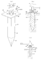
図1(a)(b)及び(c)は本発明に係る杭基礎を備えたユニット建物を地盤に設置した状態を一部断面で示す正面図、基礎部の拡大断面図、及び分解斜視図であり、図2(a)及び(b)は杭基礎と柱底部との接続構造を説明するための分解斜視図、及び断面図であり、(c)は杭基礎に打撃を加えている状態を示す説明図である。
ユニット建物1は、少なくとも四隅に鋼製角パイプからなる柱5を備えた家屋ユニット3と、各柱5の底部に対して夫々締結具50を用いて固定される杭基礎20と、を概略備えている。
柱5の底部と、杭基礎20は、本発明のユニット建物の基礎構造を構成している。
家屋ユニット3は、四隅に立設された中空四角柱状の柱5と、隣接し合う各柱5の上部間に架設された上梁6と、隣接し合う各柱5の下部間に架設された下梁7と、から構成されている。各柱5と上梁6と下梁7との間に形成される各側面には側板が夫々固定され、底面及び天面には夫々底板及び天板が固定される。 Hereinafter, the present invention will be described in detail based on the embodiments shown in the drawings.
Fig.1 (a) (b) and (c) is the front view which shows the state which installed the unit building provided with the pile foundation which concerns on this invention in the ground in a partial cross section, the expanded sectional view of a foundation part, and a disassembled perspective view 2 (a) and 2 (b) are an exploded perspective view and a sectional view for explaining the connection structure between the pile foundation and the column bottom, and FIG. 2 (c) is a state in which the pile foundation is hit. FIG.
The unit building 1 roughly includes ahouse unit 3 provided with pillars 5 made of steel square pipes at at least four corners, and a pile foundation 20 fixed to the bottom of each pillar 5 using fasteners 50 respectively. ing.
The bottom of thepillar 5 and the pile foundation 20 constitute the foundation structure of the unit building of the present invention.
Thehouse unit 3 is constructed between hollow square pillars 5 erected at the four corners, an upper beam 6 constructed between the tops of the adjacent pillars 5, and a lower portion of the adjacent pillars 5 And a lower beam 7. A side plate is fixed to each side surface formed between each pillar 5, the upper beam 6 and the lower beam 7, and a bottom plate and a top plate are fixed to the bottom surface and the top surface, respectively.
図1(a)(b)及び(c)は本発明に係る杭基礎を備えたユニット建物を地盤に設置した状態を一部断面で示す正面図、基礎部の拡大断面図、及び分解斜視図であり、図2(a)及び(b)は杭基礎と柱底部との接続構造を説明するための分解斜視図、及び断面図であり、(c)は杭基礎に打撃を加えている状態を示す説明図である。
ユニット建物1は、少なくとも四隅に鋼製角パイプからなる柱5を備えた家屋ユニット3と、各柱5の底部に対して夫々締結具50を用いて固定される杭基礎20と、を概略備えている。
柱5の底部と、杭基礎20は、本発明のユニット建物の基礎構造を構成している。
家屋ユニット3は、四隅に立設された中空四角柱状の柱5と、隣接し合う各柱5の上部間に架設された上梁6と、隣接し合う各柱5の下部間に架設された下梁7と、から構成されている。各柱5と上梁6と下梁7との間に形成される各側面には側板が夫々固定され、底面及び天面には夫々底板及び天板が固定される。 Hereinafter, the present invention will be described in detail based on the embodiments shown in the drawings.
Fig.1 (a) (b) and (c) is the front view which shows the state which installed the unit building provided with the pile foundation which concerns on this invention in the ground in a partial cross section, the expanded sectional view of a foundation part, and a disassembled perspective view 2 (a) and 2 (b) are an exploded perspective view and a sectional view for explaining the connection structure between the pile foundation and the column bottom, and FIG. 2 (c) is a state in which the pile foundation is hit. FIG.
The unit building 1 roughly includes a
The bottom of the
The
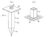
杭基礎20は、尖った先端部を含む少なくとも一部が地盤100内に打ち込まれることにより地盤内において主として水平方向への荷重を受ける杭部21と、杭部21が地盤内に打ち込まれる過程で地盤面100aと接することにより杭部の打ち込み深さの限界を定め、且つ地盤面と接することにより垂直方向への荷重を受ける接地部材30と、杭部21の上部、或いは接地部材30から上方へ突設されて各柱5の底部に対して締結具50によって固定される連結部材40と、を備えている。
本例では、四角形状の平板である接地部材30はその中央部下面を杭部21の上部に一体化され、連結部材40は杭部21の軸方向延長上にある設置部材30の上面に固定されている。杭部21と連結部材40が同一軸心状に配置されていることにより、柱5から連結部材40を経由して杭部21に加わる各種応力を効率的に杭部21が受けて支持することができる。
杭基礎20は、鉄鋼等の金属材料から構成されている。杭部21は、四角柱状(その他の多角形、或いは円柱状等々任意の断面形状でよい)の本体22と、本体22の先端部に一体化された尖端部23と、を備える。本例では杭部21の一辺の幅は30mm程度、長さは1m程度である。 In thepile foundation 20, when at least a part including the pointed end is driven into the ground 100, the pile portion 21 mainly receiving a load in the horizontal direction in the ground, and in the process of driving the pile portion 21 into the ground Grounding member 30 receives the load in the vertical direction by contacting the ground surface by determining the limit of the driving depth of the pile portion by contacting the ground surface 100a, and from the upper portion of the pile portion 21 or upward from the grounding member 30 And a connecting member 40 which is provided so as to protrude and is fixed to the bottom of each column 5 by a fastener 50.
In this example, thegrounding member 30, which is a rectangular flat plate, has its center lower surface integrated with the upper portion of the pile portion 21, and the coupling member 40 is fixed to the upper surface of the installation member 30 on the axial extension of the pile portion 21. It is done. The pile portion 21 efficiently receives and supports various stresses applied to the pile portion 21 from the pillar 5 via the connection member 40 by arranging the pile portion 21 and the connection member 40 in the same axial center shape. Can.
Thepile foundation 20 is made of a metal material such as steel. The pile portion 21 includes a main body 22 having a quadrangular prism shape (which may have any cross-sectional shape such as another polygonal shape or a cylindrical shape or the like) and a pointed end 23 integrated with the tip of the main body 22. In this example, the width of one side of the pile portion 21 is about 30 mm, and the length is about 1 m.
本例では、四角形状の平板である接地部材30はその中央部下面を杭部21の上部に一体化され、連結部材40は杭部21の軸方向延長上にある設置部材30の上面に固定されている。杭部21と連結部材40が同一軸心状に配置されていることにより、柱5から連結部材40を経由して杭部21に加わる各種応力を効率的に杭部21が受けて支持することができる。
杭基礎20は、鉄鋼等の金属材料から構成されている。杭部21は、四角柱状(その他の多角形、或いは円柱状等々任意の断面形状でよい)の本体22と、本体22の先端部に一体化された尖端部23と、を備える。本例では杭部21の一辺の幅は30mm程度、長さは1m程度である。 In the
In this example, the
The
接地部材30は、杭部21の上端部に溶接等によって一体化された平板状の部材であり、下面で地盤面100aと接することにより、家屋ユニット3の重量によって杭基礎20が必要以上に地盤内に埋没することを防止するために必要十分な面積を備える。
連結部材40は、杭部21の上端部に相当する接地部材30の上面に固定されており、柱5の平坦な底面を支持し易いように連結部材の上面は平坦状に構成されている。
本実施形態では、中空四角柱状の柱5の底面には連結穴8が形成され、中空四角柱状の連結部材40の上面には連結穴8と締結部材50を介して連結される被連結穴41が形成されている。更に、柱5の下部周壁には連結穴8と連通する作業用開口部9が形成されると共に、連結部材40の周壁には被連結穴41と連通する作業用開口部42が形成されている。本例では、柱5及び連結部材40の各4つの周壁に、夫々作業用開口部9、42が形成されている。 Theground contact member 30 is a flat member integrated with the upper end portion of the pile portion 21 by welding or the like, and the pile foundation 20 is ground more than necessary by the weight of the house unit 3 by contacting the ground surface 100a on the lower surface. It has an area sufficient to prevent it from being buried inside.
The connectingmember 40 is fixed to the upper surface of the grounding member 30 corresponding to the upper end portion of the pile portion 21. The upper surface of the connecting member is configured to be flat so as to easily support the flat bottom of the column 5.
In the present embodiment, theconnection hole 8 is formed on the bottom surface of the hollow square pillar-shaped column 5, and the connection hole 8 is connected to the upper surface of the hollow square pillar connection member 40 via the connection hole 8 and the fastening member 50. Is formed. Further, a work opening 9 communicating with the connection hole 8 is formed in the lower peripheral wall of the column 5, and a work opening 42 communicating with the connection hole 41 is formed in the peripheral wall of the connection member 40. . In the present embodiment, working openings 9 and 42 are formed in the four peripheral walls of the column 5 and the connecting member 40, respectively.
連結部材40は、杭部21の上端部に相当する接地部材30の上面に固定されており、柱5の平坦な底面を支持し易いように連結部材の上面は平坦状に構成されている。
本実施形態では、中空四角柱状の柱5の底面には連結穴8が形成され、中空四角柱状の連結部材40の上面には連結穴8と締結部材50を介して連結される被連結穴41が形成されている。更に、柱5の下部周壁には連結穴8と連通する作業用開口部9が形成されると共に、連結部材40の周壁には被連結穴41と連通する作業用開口部42が形成されている。本例では、柱5及び連結部材40の各4つの周壁に、夫々作業用開口部9、42が形成されている。 The
The connecting
In the present embodiment, the
締結具50としては、例えばツイストロック、ワンサイドボルト等を用いる。ツイストロックを用いる場合には連結穴8、及び被連結穴41を長方形状の開口とする。ツイストロック51は、例えば図2に示すように軸部材52と、軸部材の一端部に固定され連結穴8及び被連結穴41に挿通可能な固定係止片53と、軸部材の他端に回動自在に軸支され且つ連結穴8及び被連結穴41に挿通可能な可動係止片54と、を備える。ツイストロック51を用いて柱底部と連結部材40とを連結する場合には、連結穴8と被連結穴41とが連通状態となるように連結部材上面に柱底面を位置合わせした状態で、柱5に形成した作業用開口部9からツイストロック50を柱内部に差し込んでから固定係止片53を連通状態にある連結穴8及び被連結穴41の内部に差し込む。固定係止片53を連結部材の内部に入り込ませた後で、可動係止片54を90度回動させてロックすることにより、連結穴及び被連結穴から固定係止片53が脱落することなく柱と連結部材とが一体化される。
ワンサイドボルトを用いた締結作業も、作業用開口部を利用して行われる。
ユニット建物1を地盤100上に設置する工事においては、まず、家屋ユニット3の4本の柱5の底面に相当する地盤面に、接地部材30の下面が地盤面と接するように杭基礎20の杭部21を打ち込み、その後、各杭基礎20の連結部材上面に各柱底面が一対一で対応するように、クレーン等を用いて家屋ユニット3を移載する。この状態で、締結具50を用いて各柱底部と各連結部材とを連結一体化する。 As thefastener 50, for example, a twist lock, a one-side bolt or the like is used. In the case of using a twist lock, the connection hole 8 and the connection hole 41 are rectangular openings. For example, as shown in FIG. 2, the twist lock 51 is fixed to the shaft member 52, a fixed locking piece 53 fixed to one end of the shaft member and insertable into the connection hole 8 and the connected hole 41, and the other end of the shaft member. And a movable locking piece 54 rotatably supported and insertable into the connection hole 8 and the connection hole 41. When the column bottom and the connecting member 40 are connected using the twist lock 51, the column bottom is aligned with the upper surface of the connecting member so that the connecting hole 8 and the connected hole 41 are in communication with each other. After the twist lock 50 is inserted into the inside of the pillar from the working opening 9 formed in 5, the fixed locking piece 53 is inserted into the connection hole 8 and the connected hole 41 in communication. After the fixed locking piece 53 is inserted into the inside of the connecting member, the fixed locking piece 53 is detached from the connecting hole and the connected hole by rotating and locking the movable locking piece 54 by 90 degrees. Instead, the pillar and the connecting member are integrated.
The fastening operation using the one-side bolt is also performed using the operation opening.
In the work of installing the unit building 1 on theground 100, first, the ground surface of the ground foundation 30 is in contact with the ground surface such that the lower surface of the ground contact member 30 contacts the ground surface corresponding to the bottoms of the four columns 5 of the house unit 3. The pile unit 21 is driven, and then the house unit 3 is transferred using a crane or the like so that the bottoms of the columns correspond to the upper surfaces of the connection members of the pile foundations 20 one by one. In this state, the bottoms of the columns and the connection members are integrally connected using the fasteners 50.
ワンサイドボルトを用いた締結作業も、作業用開口部を利用して行われる。
ユニット建物1を地盤100上に設置する工事においては、まず、家屋ユニット3の4本の柱5の底面に相当する地盤面に、接地部材30の下面が地盤面と接するように杭基礎20の杭部21を打ち込み、その後、各杭基礎20の連結部材上面に各柱底面が一対一で対応するように、クレーン等を用いて家屋ユニット3を移載する。この状態で、締結具50を用いて各柱底部と各連結部材とを連結一体化する。 As the
The fastening operation using the one-side bolt is also performed using the operation opening.
In the work of installing the unit building 1 on the
このような簡易な作業によって、ユニット建物1の地盤への設置が完了する。
或いは、クレーン等によって家屋ユニット3を空中に保持した状態で、各柱5の底部に杭基礎20を固定し、この状態で地盤面に家屋ユニットを下降させて杭部21を地盤内に打ち込むようにしてもよい。この場合には、杭基礎を地盤に固定してから、クレーン等により吊った家屋ユニットの各柱底部を各連結部材上に位置あわせして固定するという作業がなくなり、便利である。
本発明の杭基礎20にあっては、杭部21が1m~2m程度と比較的短尺であるため、非熟練者によっても、大型ハンマー等があれば打ち込みが十分に可能であり、杭打ち用の機械や専門技術は不要である。大型ハンマーによって杭基礎を打ち込む場合には、連結部材40に直接打撃を加えても良いが、図2に示すように鉄鋼などからなる打撃用カバー45を連結部材40に被せた上で打撃用カバー及び接地部材30を介して杭部21に打撃が伝わるようにするのが好ましい。 The installation on the ground of unit building 1 is completed by such simple work.
Alternatively, with thehouse unit 3 held in the air by a crane or the like, the pile foundation 20 is fixed to the bottom of each column 5, and in this state, the house unit is lowered to the ground surface to drive the pile portion 21 into the ground. You may In this case, after fixing the pile foundation to the ground, there is no work of aligning and fixing the column bottoms of the house unit suspended by a crane or the like on each connecting member, which is convenient.
In thepile foundation 20 of the present invention, since the pile portion 21 is relatively short such as about 1 m to 2 m, even non-experts can sufficiently drive them with a large hammer etc. Machines and expertise are not required. In the case of driving the pile foundation with a large hammer, the connection member 40 may be directly hit, but as shown in FIG. It is preferable that the impact be transmitted to the pile portion 21 via the ground contact member 30.
或いは、クレーン等によって家屋ユニット3を空中に保持した状態で、各柱5の底部に杭基礎20を固定し、この状態で地盤面に家屋ユニットを下降させて杭部21を地盤内に打ち込むようにしてもよい。この場合には、杭基礎を地盤に固定してから、クレーン等により吊った家屋ユニットの各柱底部を各連結部材上に位置あわせして固定するという作業がなくなり、便利である。
本発明の杭基礎20にあっては、杭部21が1m~2m程度と比較的短尺であるため、非熟練者によっても、大型ハンマー等があれば打ち込みが十分に可能であり、杭打ち用の機械や専門技術は不要である。大型ハンマーによって杭基礎を打ち込む場合には、連結部材40に直接打撃を加えても良いが、図2に示すように鉄鋼などからなる打撃用カバー45を連結部材40に被せた上で打撃用カバー及び接地部材30を介して杭部21に打撃が伝わるようにするのが好ましい。 The installation on the ground of unit building 1 is completed by such simple work.
Alternatively, with the
In the
また、地盤の硬さを示すN値が3程度の軟弱な地盤であっても、地盤に打ち込まれた杭部21によって水平方向への応力に対する支持力を十分に維持することができる。
また、接地部材30はその下面で地盤面と接することにより、家屋ユニット3の垂直荷重を分散して支持することができる。
なお、上記実施形態では、本発明の杭基礎からなる基礎構造を適用可能な家屋ユニット3として、四隅に柱5を有したタイプを例示したが、本発明は5本以上の柱を有した家屋ユニットに対しても適用できることは言うまでもない。 In addition, even in the case of a soft ground having an N value of about 3 indicating the hardness of the ground, thepile portion 21 driven into the ground can sufficiently maintain the supporting force against the stress in the horizontal direction.
Moreover, theground contact member 30 can disperse | distribute and support the perpendicular | vertical load of the house unit 3 by contacting a ground surface in the lower surface.
In the above embodiment, as thehouse unit 3 to which the foundation structure consisting of the pile foundation of the present invention can be applied, the type having the pillars 5 at the four corners is exemplified. However, the present invention is a house having five or more pillars. Needless to say, it can be applied to units.
また、接地部材30はその下面で地盤面と接することにより、家屋ユニット3の垂直荷重を分散して支持することができる。
なお、上記実施形態では、本発明の杭基礎からなる基礎構造を適用可能な家屋ユニット3として、四隅に柱5を有したタイプを例示したが、本発明は5本以上の柱を有した家屋ユニットに対しても適用できることは言うまでもない。 In addition, even in the case of a soft ground having an N value of about 3 indicating the hardness of the ground, the
Moreover, the
In the above embodiment, as the
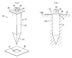
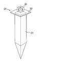
次に、図3(a)及び(b)は他の実施形態に係る杭基礎の構成を示す分解斜視図、及び地盤の打ち込んだ状態を示す断面図である。
なお、図3に示すように杭部21と連結部材40を予め一体的に製造し、杭部と連結部材との境界部分に溶接によって接地部材30を固定してもよい。この場合、接地部材30の中央部に、杭部21の本体22を挿通可能な四角形の挿通穴31を形成し、この挿通穴内に杭部の本体22を挿通した状態で両者を溶接により一体化する。また、接地部材30を位置決めするための係止突起(フランジ部)24を杭部の上部外周に設けて、接地部材30を位置決めした上で溶接してもよい。
或いは、杭部の係止突起24に対して接地部材30を固定せずに家屋ユニット3の重量によって接地部材30を地盤面100aに圧接するようにしてもよい。 Next, Fig.3 (a) and (b) are the disassembled perspective view which shows the structure of the pile foundation which concerns on other embodiment, and sectional drawing which shows the state which the ground poured in. FIG.
As shown in FIG. 3, thepile portion 21 and the connecting member 40 may be integrally manufactured in advance, and the ground member 30 may be fixed to the boundary between the pile portion and the connecting member by welding. In this case, a rectangular insertion hole 31 through which the main body 22 of the pile portion 21 can be inserted is formed in the central portion of the ground member 30, and the main body 22 of the pile portion is inserted into the insertion hole and integrated by welding. Do. In addition, a locking projection (flange portion) 24 for positioning the grounding member 30 may be provided on the upper outer periphery of the pile portion to position the grounding member 30, and then welding may be performed.
Alternatively, the groundingmember 30 may be pressed against the ground surface 100 a by the weight of the house unit 3 without fixing the grounding member 30 to the locking projection 24 of the pile portion.
なお、図3に示すように杭部21と連結部材40を予め一体的に製造し、杭部と連結部材との境界部分に溶接によって接地部材30を固定してもよい。この場合、接地部材30の中央部に、杭部21の本体22を挿通可能な四角形の挿通穴31を形成し、この挿通穴内に杭部の本体22を挿通した状態で両者を溶接により一体化する。また、接地部材30を位置決めするための係止突起(フランジ部)24を杭部の上部外周に設けて、接地部材30を位置決めした上で溶接してもよい。
或いは、杭部の係止突起24に対して接地部材30を固定せずに家屋ユニット3の重量によって接地部材30を地盤面100aに圧接するようにしてもよい。 Next, Fig.3 (a) and (b) are the disassembled perspective view which shows the structure of the pile foundation which concerns on other embodiment, and sectional drawing which shows the state which the ground poured in. FIG.
As shown in FIG. 3, the
Alternatively, the grounding
このように工場において予め杭部21、及び連結部材40と一体化すると共に、別体構造の接地部材30を現場で杭部に挿通するようにしても良い。即ち、杭部の上部外周適所に接地部材を係止する係止突起24を設けておき、接地部材に設けた挿通穴内に杭部をその尖端側から挿通した際に係止突起24によって接地部材が係止されるように構成する。この場合、接地部材を杭部(係止突起)に対して溶接により固定してもよいし、固定しなくてもよい。接地部材を杭部に固定しない場合には、杭部に対して着脱自在であり、杭部を接地部材の挿通穴31に挿通した状態で地盤面に打ち込むことにより、係止突起24と地盤面との間で接地部材を挟圧保持することとなる。
このように接地部材と杭部とを固定しない場合には、杭基礎を2つのパーツに分けて運搬することができるため、取扱性が高まる。また、杭部に対して接地部材を溶接等によって固定しない場合には溶接作業を省略することができ、製造手数、製造コストを低減できる。 As described above, while being integrated with thepile portion 21 and the connection member 40 in the factory in advance, the ground member 30 having a separate structure may be inserted into the pile portion on site. That is, the locking projection 24 for locking the grounding member is provided at an appropriate position on the upper outer periphery of the pile portion, and the grounding protrusion is formed by the locking projection 24 when the pile portion is inserted from the tip end into the insertion hole provided in the grounding member. Are configured to be locked. In this case, the ground contact member may or may not be fixed to the pile portion (the locking projection) by welding. In the case where the ground contact member is not fixed to the pile portion, it is detachable with respect to the pile portion, and the engagement projection 24 and the ground surface are obtained by driving the pile portion into the ground surface in a state inserted through the insertion hole 31 of the ground contact member. And hold the grounding member between them.
When the ground contact member and the pile portion are not fixed in this manner, the pile foundation can be divided into two parts and transported, so that the handling property is enhanced. In addition, when the grounding member is not fixed to the pile portion by welding or the like, the welding operation can be omitted, and the manufacturing cost and the manufacturing cost can be reduced.
このように接地部材と杭部とを固定しない場合には、杭基礎を2つのパーツに分けて運搬することができるため、取扱性が高まる。また、杭部に対して接地部材を溶接等によって固定しない場合には溶接作業を省略することができ、製造手数、製造コストを低減できる。 As described above, while being integrated with the
When the ground contact member and the pile portion are not fixed in this manner, the pile foundation can be divided into two parts and transported, so that the handling property is enhanced. In addition, when the grounding member is not fixed to the pile portion by welding or the like, the welding operation can be omitted, and the manufacturing cost and the manufacturing cost can be reduced.
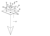
次に、図4は本発明の杭基礎の変形例を示す斜視図である。
この杭基礎20は、接地部材30に対して連結部材40を着脱自在、或いは位置変位自在に構成した点が特徴的である。
連結部材40には外周から鍔状に張り出した被固定板43が一体化されており、被固定板43の適所、本例では四隅に取付け穴43aが貫通している。一方、接地部材30側には各取付け穴43aと対応する位置に十字状の穴30aが貫通形成されており、ボルト(例えば、高テンションボルト)44を取付け穴43aと穴30aに挿通してナットにより締結することにより、連結部材40を接地部材30に固定できる。杭部21を地盤面に打ち込んだ後で、各連結部材の上面を家屋ユニットの柱底部と位置合わせする際に微妙に位置が合わない場合には、ナットを緩めて十字の穴30aに沿ってボルト44の位置を移動させることにより、各連結部材の上面を家屋ユニットの柱底部と位置合わせが可能となる。
取付け穴43aの形状は十字に限定されるものではなく、多様な方向へ連結部材40の位置を調整できる形状であればよい。
取付け穴43aとボルト44とナットは、連結部材の位置を調整する位置調整機構を構成している。
なお、接地部材に対する連結部材の位置を微調整するための上記構造は、他の実施形態における接地部材と連結部材との関係にも適用することができる。 Next, FIG. 4 is a perspective view which shows the modification of the pile foundation of this invention.
Thepile foundation 20 is characterized in that the connecting member 40 is configured to be removable or displaceable with respect to the ground contact member 30.
A fixedplate 43 protruding in a bowl shape from the outer periphery is integrated with the connecting member 40, and mounting holes 43a pass through at appropriate positions of the fixed plate 43, in this example, at four corners. On the other hand, on the ground member 30 side, a cross-shaped hole 30a is formed through at a position corresponding to each mounting hole 43a, and a bolt (for example, high tension bolt) 44 is inserted through the mounting hole 43a and the hole 30a The connecting member 40 can be fixed to the grounding member 30 by fastening according to the following. If the top of each connecting member is not aligned with the bottom of the column of the house unit after the pile 21 is driven into the ground surface, loosen the nut and extend along the cross hole 30a. By moving the position of the bolt 44, the top surface of each connecting member can be aligned with the column bottom of the house unit.
The shape of the mountinghole 43a is not limited to a cross, and may be any shape as long as the position of the connecting member 40 can be adjusted in various directions.
The mountinghole 43a, the bolt 44 and the nut constitute a position adjusting mechanism for adjusting the position of the connecting member.
The above-described structure for finely adjusting the position of the connection member with respect to the ground contact member can also be applied to the relationship between the ground contact member and the connection member in the other embodiments.
この杭基礎20は、接地部材30に対して連結部材40を着脱自在、或いは位置変位自在に構成した点が特徴的である。
連結部材40には外周から鍔状に張り出した被固定板43が一体化されており、被固定板43の適所、本例では四隅に取付け穴43aが貫通している。一方、接地部材30側には各取付け穴43aと対応する位置に十字状の穴30aが貫通形成されており、ボルト(例えば、高テンションボルト)44を取付け穴43aと穴30aに挿通してナットにより締結することにより、連結部材40を接地部材30に固定できる。杭部21を地盤面に打ち込んだ後で、各連結部材の上面を家屋ユニットの柱底部と位置合わせする際に微妙に位置が合わない場合には、ナットを緩めて十字の穴30aに沿ってボルト44の位置を移動させることにより、各連結部材の上面を家屋ユニットの柱底部と位置合わせが可能となる。
取付け穴43aの形状は十字に限定されるものではなく、多様な方向へ連結部材40の位置を調整できる形状であればよい。
取付け穴43aとボルト44とナットは、連結部材の位置を調整する位置調整機構を構成している。
なお、接地部材に対する連結部材の位置を微調整するための上記構造は、他の実施形態における接地部材と連結部材との関係にも適用することができる。 Next, FIG. 4 is a perspective view which shows the modification of the pile foundation of this invention.
The
A fixed
The shape of the mounting
The mounting
The above-described structure for finely adjusting the position of the connection member with respect to the ground contact member can also be applied to the relationship between the ground contact member and the connection member in the other embodiments.
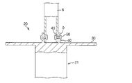
次に、図5は柱底部と連結部材との連結構造の他の例を示す断面図であり、この例に係る連結部材40は上面が開放した四角柱であり、連結部材40の上面開口内に柱5の下部が嵌合し得るように寸法設定されている。連結部材の周壁と柱下部の周壁には夫々互いに連通する連結穴9、43が形成されており、両連結穴9、43内に、ワンサイドボルト56等の締結具を挿着して両部材を固定する。ワンサイドボルト56はその一端部を両連結穴9、43内に外部から差し込んだあとで他端部を操作することにより、一端部に設けた拡開片が外径方向へ突出して連結穴9、43から抜け落ちることがないように固定される。
次に、接地部材を補強するリブをその上面、或いは下面に設けても良い。図6(a)(b)は補強用リブ35を接地部材30の下面に突設した状態を示しており、リブ35の先端をV字状に尖らせることにより、地盤面に食い込むアンカー効果によって水平方向への位置ずれを防止する効果を期待することができる。 Next, FIG. 5 is a cross-sectional view showing another example of the connection structure between the column bottom portion and the connecting member, and the connectingmember 40 according to this example is a square pole whose upper surface is open. The lower part of the column 5 is dimensioned so that it can be fitted. Connection holes 9 and 43 communicating with each other are formed in the peripheral wall of the connection member and the peripheral wall of the lower portion of the column, and a fastener such as one side bolt 56 is inserted into both connection holes 9 and 43 Fix the The one-side bolt 56 has one end inserted into the connection holes 9 and 43 from the outside and then the other end is manipulated, whereby the expanded piece provided at the one end protrudes in the outer diameter direction and the connection hole 9 , 43 fixed so as not to fall off.
Next, a rib for reinforcing the ground contact member may be provided on the upper surface or the lower surface. 6 (a) and 6 (b) show a state in which the reinforcingrib 35 is provided on the lower surface of the grounding member 30, and by sharpening the tip of the rib 35 in a V shape, the anchor effect biting into the ground surface is obtained. The effect of preventing positional deviation in the horizontal direction can be expected.
次に、接地部材を補強するリブをその上面、或いは下面に設けても良い。図6(a)(b)は補強用リブ35を接地部材30の下面に突設した状態を示しており、リブ35の先端をV字状に尖らせることにより、地盤面に食い込むアンカー効果によって水平方向への位置ずれを防止する効果を期待することができる。 Next, FIG. 5 is a cross-sectional view showing another example of the connection structure between the column bottom portion and the connecting member, and the connecting
Next, a rib for reinforcing the ground contact member may be provided on the upper surface or the lower surface. 6 (a) and 6 (b) show a state in which the reinforcing
次に、図7(a)及び(b)は本発明の他の実施形態に係る杭基礎20を備えたユニット家屋の構成例を示す分解斜視図、設置状態を示す正面図であり、(c)は変形例に係る位置決めベース部材の構成説明図である。
実施形態に係るユニット建物1は、少なくとも四隅に柱5を備えた箱状の家屋ユニット3と、各柱5の底部に対して夫々締結具50を用いて固定される杭基礎20と、を備える。
杭基礎20は、地盤に打ち込まれる杭部21と、杭部21の上部に固定されて各柱5の底部に対して締結具50によって固定される連結部材40と、各柱の底部と対応する位置に杭部21を差し込む位置決め穴61を有した位置決めベース部材(接地部材)60と、杭部が位置決めベース部材60の位置決め穴61に差し込まれた時に杭部の差込み長を規制するために杭部21の上部に設けられた係止突起(フランジ部)24と、を備える。そして、地盤面に位置決めベース部材60を定置した状態で各位置決め穴61を介して地盤面に各杭基礎の杭部を打ち込むように構成されている。 Next, FIGS. 7A and 7B are an exploded perspective view showing a configuration example of a unit house provided with apile foundation 20 according to another embodiment of the present invention, and a front view showing an installation state (c ) Is a configuration explanatory view of a positioning base member according to a modification.
The unit building 1 according to the embodiment includes a box-like house unit 3 provided with pillars 5 at at least four corners, and a pile foundation 20 fixed to the bottom of each pillar 5 using fasteners 50 respectively. .
Thepile foundation 20 corresponds to the pile portion 21 driven into the ground, the connecting member 40 fixed to the upper portion of the pile portion 21 and fixed to the bottom of each pillar 5 by the fastener 50, and the bottom of each pillar A positioning base member (grounding member) 60 having a positioning hole 61 into which the pile portion 21 is inserted at a position, and a pile for restricting the insertion length of the pile portion when the pile portion is inserted into the positioning hole 61 of the positioning base member 60 And a locking projection (flange portion) 24 provided on the upper portion of the portion 21. And it is comprised so that the pile part of each pile foundation may be driven into a ground surface via each positioning hole 61 in the state which fixed the positioning base member 60 on the ground surface.
実施形態に係るユニット建物1は、少なくとも四隅に柱5を備えた箱状の家屋ユニット3と、各柱5の底部に対して夫々締結具50を用いて固定される杭基礎20と、を備える。
杭基礎20は、地盤に打ち込まれる杭部21と、杭部21の上部に固定されて各柱5の底部に対して締結具50によって固定される連結部材40と、各柱の底部と対応する位置に杭部21を差し込む位置決め穴61を有した位置決めベース部材(接地部材)60と、杭部が位置決めベース部材60の位置決め穴61に差し込まれた時に杭部の差込み長を規制するために杭部21の上部に設けられた係止突起(フランジ部)24と、を備える。そして、地盤面に位置決めベース部材60を定置した状態で各位置決め穴61を介して地盤面に各杭基礎の杭部を打ち込むように構成されている。 Next, FIGS. 7A and 7B are an exploded perspective view showing a configuration example of a unit house provided with a
The unit building 1 according to the embodiment includes a box-
The
位置決めベース部材60は、図1の実施形態における接地部材30と同様に垂直方向下方へ向かう荷重を支持する機能を果たす。必要に応じて、位置決めベース部材60の上面、或いは下面に図6に示した如き補強用のリブを突設してもよい。
図7(a)(b)に示した位置決めベース部材60は、家屋ユニット3の底面の周縁に沿った四角い環状板であり、家屋ユニットの各柱5の底部に対応する位置には杭部21を差し込むための位置決め穴61が貫通形成されている。
位置決めベース部材60を用いることにより、地盤面に位置決めベース部材60を定置しておき、杭部21を位置決め穴61に打ち込みさえすれば、杭部の位置決めが完了する。このため、巻き尺等を用いて事前に杭を打ち込む位置を正確に測量する作業が不要となり、被災地等において非専門家が家屋ユニット3の基礎工事を極めて容易に実施することが可能となる。この場合、位置決めベース部材60は杭基礎の一部として、家屋ユニット3に組み付けられる。また、地盤に段差がある場合であっても、平板状の位置決めベースを地盤面に定置することにより段差が家屋ユニットに与える影響を緩和することができる。 Thepositioning base member 60 performs the function of supporting vertically downward load similar to the ground contact member 30 in the embodiment of FIG. If necessary, a reinforcing rib as shown in FIG. 6 may be provided on the upper surface or the lower surface of the positioning base member 60 in a protruding manner.
Thepositioning base member 60 shown in FIGS. 7 (a) and 7 (b) is a square annular plate along the periphery of the bottom surface of the house unit 3, and a pile portion 21 is provided at a position corresponding to the bottom of each column 5 of the house unit. A positioning hole 61 is formed through for inserting the plug.
By using thepositioning base member 60, the positioning base member 60 is fixed on the ground surface, and if the pile portion 21 is driven into the positioning hole 61, the positioning of the pile portion is completed. For this reason, the work which measures the position which strikes a pile in advance correctly using a tape measure etc. becomes unnecessary, and it becomes possible for a non-expert to carry out foundation work of house unit 3 extremely easily in a stricken area etc. In this case, the positioning base member 60 is assembled to the house unit 3 as a part of the pile foundation. In addition, even in the case where there is a step in the ground, the influence of the step on the house unit can be alleviated by fixing the flat positioning base on the ground surface.
図7(a)(b)に示した位置決めベース部材60は、家屋ユニット3の底面の周縁に沿った四角い環状板であり、家屋ユニットの各柱5の底部に対応する位置には杭部21を差し込むための位置決め穴61が貫通形成されている。
位置決めベース部材60を用いることにより、地盤面に位置決めベース部材60を定置しておき、杭部21を位置決め穴61に打ち込みさえすれば、杭部の位置決めが完了する。このため、巻き尺等を用いて事前に杭を打ち込む位置を正確に測量する作業が不要となり、被災地等において非専門家が家屋ユニット3の基礎工事を極めて容易に実施することが可能となる。この場合、位置決めベース部材60は杭基礎の一部として、家屋ユニット3に組み付けられる。また、地盤に段差がある場合であっても、平板状の位置決めベースを地盤面に定置することにより段差が家屋ユニットに与える影響を緩和することができる。 The
The
By using the
或いは、工場、或いは現場において予め、位置決めベース部材60の各位置決め穴61内に、連結部材40、係止突起24を備えた杭部21を打ち込んだ状態で溶接しておき、この位置決め部材ユニットを地盤面に定置する際に杭部21を地盤内に打ち込むことにより位置決め部材を含んだ杭基礎の設置を完了するようにしてもよい。
或いは、位置決め穴を有しない位置決めベース部材(接地部材)の四隅の上面と下面に夫々連結部材と杭部を溶接により固定した位置決め部材ユニットを予め構築しておき、これを現場に運搬して利用するようにしてもよい。
なお、位置決めベース部材60は係止突起24、或いは杭部21と溶接により一体化してもよいが、一体化しなくてもよい。仮に、位置決めベース部材と杭部とを一体化しない場合においても、位置決めベース部材は係止突起24と地盤面との間に挟まれた状態で家屋からの荷重を受けるので、垂直方向下方への荷重を支持する機能は十分に維持することができる。 Alternatively, welding is performed in advance in the factory or on the spot in the state where theconnection member 40 and the pile portion 21 provided with the locking projection 24 are driven into each positioning hole 61 of the positioning base member 60. It is possible to complete the installation of the pile foundation including the positioning member by driving the pile portion 21 into the ground when setting it on the ground surface.
Alternatively, positioning member units in which connecting members and piles are fixed by welding on the upper and lower surfaces of the four corners of the positioning base member (grounding member) having no positioning hole are constructed in advance and transported to the site for use You may do it.
Thepositioning base member 60 may be integrated with the locking projection 24 or the pile portion 21 by welding, but may not be integrated. Even if the positioning base member and the pile portion are not integrated, the positioning base member receives the load from the house in a state of being sandwiched between the locking projection 24 and the ground surface, so that it is vertically downward The ability to support the load can be well maintained.
或いは、位置決め穴を有しない位置決めベース部材(接地部材)の四隅の上面と下面に夫々連結部材と杭部を溶接により固定した位置決め部材ユニットを予め構築しておき、これを現場に運搬して利用するようにしてもよい。
なお、位置決めベース部材60は係止突起24、或いは杭部21と溶接により一体化してもよいが、一体化しなくてもよい。仮に、位置決めベース部材と杭部とを一体化しない場合においても、位置決めベース部材は係止突起24と地盤面との間に挟まれた状態で家屋からの荷重を受けるので、垂直方向下方への荷重を支持する機能は十分に維持することができる。 Alternatively, welding is performed in advance in the factory or on the spot in the state where the
Alternatively, positioning member units in which connecting members and piles are fixed by welding on the upper and lower surfaces of the four corners of the positioning base member (grounding member) having no positioning hole are constructed in advance and transported to the site for use You may do it.
The
或いは、位置決めベース部材60を地盤面に配置して各位置決め穴から露出した地盤面にマークを形成しておき、その後位置決めベース部材を除去してから図1の実施形態に係る杭基礎20(接地部材30を備えている)をマークした地盤部分に打ち込むようにしてもよい。この場合の位置決めベース部材は単なる杭基礎の位置合わせ手段として用いられており、基礎の一部として組み込まれることはない。このため、金属製とする必要はなく、木製、あるいは樹脂製であってもよい。
なお、四角い環状の位置決めベース部材60の形状は図7(a)に示したものに限定される訳ではなく種々変形が可能である。例えば、図7(c)のように位置決めベースの内周の各コーナー部に張出し部63を設けて杭部21が打ち込まれる部分周辺の接地面積を広く確保するようにしてもよい。 Alternatively, thepositioning base member 60 may be disposed on the ground surface, and marks may be formed on the ground surface exposed from each positioning hole, and then the positioning base member may be removed before the pile foundation 20 (grounding according to the embodiment of FIG. It is also possible to drive into the ground portion marked (provided with the member 30). The positioning base member in this case is used merely as a means for aligning the pile foundation and is not incorporated as a part of the foundation. For this reason, it does not need to be metal and may be wooden or resin.
The shape of the square annularpositioning base member 60 is not limited to that shown in FIG. 7A, and various modifications are possible. For example, as shown in FIG. 7C, projecting portions 63 may be provided at each corner portion of the inner periphery of the positioning base to secure a wide ground area around the portion where the pile portion 21 is driven.
なお、四角い環状の位置決めベース部材60の形状は図7(a)に示したものに限定される訳ではなく種々変形が可能である。例えば、図7(c)のように位置決めベースの内周の各コーナー部に張出し部63を設けて杭部21が打ち込まれる部分周辺の接地面積を広く確保するようにしてもよい。 Alternatively, the
The shape of the square annular
本例に係る位置決めベース部材60は四角い環状板として構成されているが、図8(a)に示すように家屋ユニット3の底面全体をカバーする面積を有した非環状の板材としてもよいし、同図(b)に示すように2つの隣接する柱5の下部に対応した長さを有した細幅の板材であってもよい。
なお、図8の位置決めベース部材60に位置決め穴61を設けずに、家屋ユニットの柱下部に対応する部位に、杭部21及び連結部材40を溶接により一体化した位置決めベースユニットを構築してもよい。
何れにしても位置決めベース部材を杭基礎の一部として家屋ユニットの基礎に組み込むことにより、面積の広い接地部材として利用することが可能となる。即ち、図1の実施形態のように杭部と接地部材を予め一体する場合には、運搬や取扱上の理由から接地部材として極端に面積の広いものを使用することに限界があるが、別体構造の位置決めベースを現場で組み付けることにより、広い接地面積を確保することができる。 Although positioningbase member 60 concerning this example is constituted as a square annular board, as shown in Drawing 8 (a), it is good also as non-annular board material which has an area which covers the whole bottom face of house unit 3, It may be a narrow plate material having a length corresponding to the lower part of two adjacent columns 5 as shown in FIG.
Even if thepositioning hole 61 is not provided in the positioning base member 60 of FIG. 8, the positioning base unit may be constructed by integrating the pile portion 21 and the connecting member 40 by welding at a portion corresponding to the lower portion of the column of the house unit. Good.
In any case, by incorporating the positioning base member into the foundation of the house unit as a part of the pile foundation, it can be used as a wide-area grounding member. That is, in the case where the pile portion and the grounding member are integrated in advance as in the embodiment of FIG. 1, there is a limit in using an extremely wide grounding member as the grounding member for transportation and handling reasons. By assembling the positioning base of the body structure on site, a wide ground area can be secured.
なお、図8の位置決めベース部材60に位置決め穴61を設けずに、家屋ユニットの柱下部に対応する部位に、杭部21及び連結部材40を溶接により一体化した位置決めベースユニットを構築してもよい。
何れにしても位置決めベース部材を杭基礎の一部として家屋ユニットの基礎に組み込むことにより、面積の広い接地部材として利用することが可能となる。即ち、図1の実施形態のように杭部と接地部材を予め一体する場合には、運搬や取扱上の理由から接地部材として極端に面積の広いものを使用することに限界があるが、別体構造の位置決めベースを現場で組み付けることにより、広い接地面積を確保することができる。 Although positioning
Even if the
In any case, by incorporating the positioning base member into the foundation of the house unit as a part of the pile foundation, it can be used as a wide-area grounding member. That is, in the case where the pile portion and the grounding member are integrated in advance as in the embodiment of FIG. 1, there is a limit in using an extremely wide grounding member as the grounding member for transportation and handling reasons. By assembling the positioning base of the body structure on site, a wide ground area can be secured.
家屋ユニットの軸組を構成する柱が三本、或いは五本以上ある場合には、各柱に対応した位置に杭基礎20を用いて基礎を構築する。
なお、上記各実施形態では、家屋ユニット3の外周縁から接地部材30、或いは位置決めベース部材60の一部が外側に突出した構成例を示したが、接地部材30上における連結部材40の位置、或いは位置決めベース部材上における位置決め穴61の位置を種々調整することにより、家屋ユニット外周縁からの接地部材30、或いは位置決めベース部材の突出幅を減少させるようにしてもよい。
具体的には、例えば図9に示すように杭部21に対する連結部材40の位置をずらしておくことにより、家屋ユニット外周縁から接地部材30がはみ出ることがないようにすることができる。
このように杭部と連結部材は必ずしも同一軸線上に配置しなくてもよい。 In the case where there are three or five or more pillars constituting the framework of the house unit, a foundation is constructed using thepile foundation 20 at a position corresponding to each pillar.
In each of the above embodiments, the groundingmember 30 or a part of the positioning base member 60 protrudes outward from the outer peripheral edge of the house unit 3, but the position of the connecting member 40 on the grounding member 30; Alternatively, the projection width of the grounding member 30 or the positioning base member from the outer periphery of the house unit may be reduced by variously adjusting the position of the positioning hole 61 on the positioning base member.
Specifically, for example, as shown in FIG. 9, by shifting the position of the connectingmember 40 with respect to the pile portion 21, it is possible to prevent the grounding member 30 from protruding from the outer periphery of the house unit.
Thus, the pile portion and the connecting member do not necessarily have to be arranged on the same axis.
なお、上記各実施形態では、家屋ユニット3の外周縁から接地部材30、或いは位置決めベース部材60の一部が外側に突出した構成例を示したが、接地部材30上における連結部材40の位置、或いは位置決めベース部材上における位置決め穴61の位置を種々調整することにより、家屋ユニット外周縁からの接地部材30、或いは位置決めベース部材の突出幅を減少させるようにしてもよい。
具体的には、例えば図9に示すように杭部21に対する連結部材40の位置をずらしておくことにより、家屋ユニット外周縁から接地部材30がはみ出ることがないようにすることができる。
このように杭部と連結部材は必ずしも同一軸線上に配置しなくてもよい。 In the case where there are three or five or more pillars constituting the framework of the house unit, a foundation is constructed using the
In each of the above embodiments, the grounding
Specifically, for example, as shown in FIG. 9, by shifting the position of the connecting
Thus, the pile portion and the connecting member do not necessarily have to be arranged on the same axis.
次に、図10(a)及び(b)は本発明の他の実施形態に係る杭基礎構造を備えたユニット建物の一部断面正面図、及び要部拡大断面図である。なお、図1と同一部分には同一符号を付して説明する。
本実施形態に係るユニット建物1を構成する家屋ユニット3は、四隅に設けた鋼製角パイプからなる柱5とは別に、隣接する柱間に間柱70を備えている。間柱70は、上下位置関係にて対向する上梁6と下梁7との間に跨って配置されている。この間柱7の下部を地盤面に固定するために、図1等に示した杭基礎20を適用することができる。
即ち、ユニット建物1は、少なくとも四隅に設けた柱5、隣接する柱の下部間を連結する下梁7、及び隣接する柱5間に配置されて下部を下梁に固定された間柱70を有した家屋ユニット3と、各柱5、及び間柱70の底部を夫々支持する杭基礎20と、を備え、間柱を支持する杭基礎20は、先部を含む少なくとも一部が地盤内に打ち込まれる杭部21と、杭部が地盤内に打ち込まれる過程で地盤面と接することにより該杭部の打ち込み深さの限界を定める接地部材30と、杭部の上部、或いは該接地部材から上方へ突設されて間柱の下部と対応する下梁の底部に対して固定される連結部材40と、を備えている。 Next, FIGS. 10 (a) and 10 (b) are a partial cross-sectional front view and a main part enlarged cross-sectional view of a unit building provided with a pile foundation structure according to another embodiment of the present invention. The same parts as in FIG. 1 will be described with the same reference numerals.
Thehouse unit 3 which comprises the unit building 1 which concerns on this embodiment is provided with the stud 70 between adjacent pillars separately from the pillar 5 which consists of steel square pipes provided in the four corners. The stud 70 is disposed straddling between the upper beam 6 and the lower beam 7 which face each other in the vertical positional relationship. In order to fix the lower part of the stud 7 to the ground surface, the pile foundation 20 shown in FIG. 1 or the like can be applied.
That is, the unit building 1 haspillars 5 provided at at least four corners, lower beams 7 connecting between lower portions of adjacent columns, and studs 70 disposed between adjacent pillars 5 and fixed to lower beams at lower portions. The pile foundation 20 including the house unit 3 and the pile foundation 20 for supporting the bottom of each pillar 5 and the stud 70, the pile foundation 20 for supporting the stud is a pile in which at least a part including the tip is driven into the ground. Grounding member 30 which determines the limit of the driving depth of the pile portion by contacting the ground portion in the process of driving the portion 21 and the pile portion into the ground, and projecting upward from the upper portion of the pile portion or the ground member And a connecting member 40 fixed to the bottom of the lower beam and the corresponding lower beam.
本実施形態に係るユニット建物1を構成する家屋ユニット3は、四隅に設けた鋼製角パイプからなる柱5とは別に、隣接する柱間に間柱70を備えている。間柱70は、上下位置関係にて対向する上梁6と下梁7との間に跨って配置されている。この間柱7の下部を地盤面に固定するために、図1等に示した杭基礎20を適用することができる。
即ち、ユニット建物1は、少なくとも四隅に設けた柱5、隣接する柱の下部間を連結する下梁7、及び隣接する柱5間に配置されて下部を下梁に固定された間柱70を有した家屋ユニット3と、各柱5、及び間柱70の底部を夫々支持する杭基礎20と、を備え、間柱を支持する杭基礎20は、先部を含む少なくとも一部が地盤内に打ち込まれる杭部21と、杭部が地盤内に打ち込まれる過程で地盤面と接することにより該杭部の打ち込み深さの限界を定める接地部材30と、杭部の上部、或いは該接地部材から上方へ突設されて間柱の下部と対応する下梁の底部に対して固定される連結部材40と、を備えている。 Next, FIGS. 10 (a) and 10 (b) are a partial cross-sectional front view and a main part enlarged cross-sectional view of a unit building provided with a pile foundation structure according to another embodiment of the present invention. The same parts as in FIG. 1 will be described with the same reference numerals.
The
That is, the unit building 1 has
杭基礎20は、尖った先端部を含む少なくとも一部が地盤100内に打ち込まれることにより地盤内において主として水平方向への荷重を受ける杭部21と、杭部21が地盤内に打ち込まれる過程で地盤面100aと接することにより杭部の打ち込み深さの限界を定め、且つ地盤面と接することにより垂直方向への荷重を受ける接地部材30と、杭部21の上部、或いは接地部材30から上方へ突設された連結部材40と、を備えている。
四隅に位置する柱5の下部は杭基礎の上部と直接連結可能であるが、間柱70の下部と杭基礎20の上部との間には下梁7が介在している。本例では間柱70の下部は下梁7の上面とボルト等により固定する一方で、杭基礎20の上部を下梁7の下面とボルト等により固定することにより、下梁を介して間柱と杭基礎20とを連結している。
即ち、工場においてユニット家屋3を製造する際に、予め間柱70の下面にフランジ状に連接板71を溶接等によって予め一体化すると共に、この連接板71を下梁の上面にボルト、或いは溶接により固定する。 In thepile foundation 20, when at least a part including the pointed end is driven into the ground 100, the pile portion 21 mainly receiving a load in the horizontal direction in the ground, and in the process of driving the pile portion 21 into the ground Grounding member 30 receives the load in the vertical direction by contacting the ground surface by determining the limit of the driving depth of the pile portion by contacting the ground surface 100a, and from the upper portion of the pile portion 21 or upward from the grounding member 30 And a connecting member 40 provided in a protruding manner.
Although the lower part ofpillar 5 located in four corners can be directly connected with the upper part of a pile foundation, lower beam 7 intervenes between the lower part of stud 70 and the upper part of pile foundation 20. In this example, the lower part of the stud 70 is fixed to the upper surface of the lower beam 7 by a bolt or the like, while the upper part of the pile foundation 20 is fixed to the lower surface of the lower beam 7 by a bolt or the like. The foundation 20 is connected.
That is, when manufacturing theunit house 3 in a factory, the connecting plate 71 is integrated in advance in the form of a flange on the lower surface of the stud 70 by welding or the like, and the connecting plate 71 is bolted to the upper surface of the lower beam or Fix it.
四隅に位置する柱5の下部は杭基礎の上部と直接連結可能であるが、間柱70の下部と杭基礎20の上部との間には下梁7が介在している。本例では間柱70の下部は下梁7の上面とボルト等により固定する一方で、杭基礎20の上部を下梁7の下面とボルト等により固定することにより、下梁を介して間柱と杭基礎20とを連結している。
即ち、工場においてユニット家屋3を製造する際に、予め間柱70の下面にフランジ状に連接板71を溶接等によって予め一体化すると共に、この連接板71を下梁の上面にボルト、或いは溶接により固定する。 In the
Although the lower part of
That is, when manufacturing the
また、杭基礎20としては図1の実施形態に係るものを流用し、工場において杭基礎20上部の連結部材40の上面に溶接等によってフランジ状に連接板73を一体化しておく。
現場では、間柱直下に位置する下梁7の下面に杭基礎20の連接板73をボルト等により固定する作業を実施すれば、間柱に対する杭基礎の組付けが完了する。
間柱70の下部と接する下梁7には必要に応じて、下梁を補強するための補強部材7aを固定しておく。
間柱に対して組み付けられる杭基礎を構成する杭部21は、横方向荷重を支持し、接地部材30は垂直方向への荷重を支持する機能を発揮する。
なお、間柱に対して組み付け可能な杭基礎としては、図1の実施形態に係るものの他に、図3、図6、図9に示したタイプも含まれる。 Further, as thepile foundation 20, the one according to the embodiment of FIG. 1 is used, and the connecting plate 73 is integrated in a flange shape by welding or the like on the upper surface of the connecting member 40 at the top of the pile foundation 20 in a factory.
At the site, the work of fixing the connectingplate 73 of the pile foundation 20 with a bolt or the like on the lower surface of the lower beam 7 located immediately below the stud is performed to complete the assembly of the pile foundation to the stud.
A reinforcingmember 7a for reinforcing the lower beam is fixed to the lower beam 7 in contact with the lower portion of the stud 70, if necessary.
Thepile part 21 which comprises the pile foundation assembled | attached with respect to a stud supports a horizontal direction load, and the grounding member 30 exhibits the function to support the load to a perpendicular direction.
In addition, as a pile foundation which can be assembled | attached to a stud, the type shown in FIG.3, FIG.6, FIG.9 other than what concerns on embodiment of FIG. 1 is also contained.
現場では、間柱直下に位置する下梁7の下面に杭基礎20の連接板73をボルト等により固定する作業を実施すれば、間柱に対する杭基礎の組付けが完了する。
間柱70の下部と接する下梁7には必要に応じて、下梁を補強するための補強部材7aを固定しておく。
間柱に対して組み付けられる杭基礎を構成する杭部21は、横方向荷重を支持し、接地部材30は垂直方向への荷重を支持する機能を発揮する。
なお、間柱に対して組み付け可能な杭基礎としては、図1の実施形態に係るものの他に、図3、図6、図9に示したタイプも含まれる。 Further, as the
At the site, the work of fixing the connecting
A reinforcing
The
In addition, as a pile foundation which can be assembled | attached to a stud, the type shown in FIG.3, FIG.6, FIG.9 other than what concerns on embodiment of FIG. 1 is also contained.
或いは、柱5の下部に固定される杭部21(連結部材40)と、位置決めベース部材60とを組み合わせた図7、図8のユニット建物において柱間に間柱を設ける場合には、柱用の位置決めベース部材を間柱用の接地部材として共用してもよい。即ち、位置決めベース部材6の位置決め穴61間に間柱用の杭部を差し込む位置決め穴を形成することにより、位置決めベースを間柱用の杭部にも共用することが可能となる。
本発明に係る杭基礎を備えたユニット建物は、家屋ユニットの柱の下部を地盤に固定する基礎工事において、杭部が短尺(例えば、1m~2m)な簡易な構造の杭基礎を使用しているので、運搬に便利であり、被災地等のように十分な重機、機材、専門の作業員を確保することができない状況下においても、比較的容易、且つ短期間に家屋ユニットを地盤に設置することができる。 Alternatively, in the case of providing a stud between the pillars in the unit building of FIGS. 7 and 8 in which the pile portion 21 (connection member 40) fixed to the lower part of thepillar 5 and the positioning base member 60 are combined, The positioning base member may be shared as a grounding member for the stud. That is, by forming the positioning holes into which the pile portions for the pillars are inserted between the positioning holes 61 of the positioning base member 6, the positioning base can be shared with the pile portions for the pillars.
The unit building provided with the pile foundation according to the present invention uses a pile foundation having a simple structure with a short pile portion (for example, 1 m to 2 m) in foundation work to fix the lower part of the column of house unit to the ground. It is convenient for transportation, and it is relatively easy to set up a house unit on the ground in a short period of time, even under circumstances where sufficient heavy equipment, equipment and specialized workers can not be secured as in the disaster area can do.
本発明に係る杭基礎を備えたユニット建物は、家屋ユニットの柱の下部を地盤に固定する基礎工事において、杭部が短尺(例えば、1m~2m)な簡易な構造の杭基礎を使用しているので、運搬に便利であり、被災地等のように十分な重機、機材、専門の作業員を確保することができない状況下においても、比較的容易、且つ短期間に家屋ユニットを地盤に設置することができる。 Alternatively, in the case of providing a stud between the pillars in the unit building of FIGS. 7 and 8 in which the pile portion 21 (connection member 40) fixed to the lower part of the
The unit building provided with the pile foundation according to the present invention uses a pile foundation having a simple structure with a short pile portion (for example, 1 m to 2 m) in foundation work to fix the lower part of the column of house unit to the ground. It is convenient for transportation, and it is relatively easy to set up a house unit on the ground in a short period of time, even under circumstances where sufficient heavy equipment, equipment and specialized workers can not be secured as in the disaster area can do.
杭基礎は、杭部を地盤面に打ち込んだときに接地部材が地盤面と接して垂直下向きの荷重を支持するため、家屋ユニットが地盤内に陥没することを防止でき、また杭部が水平方向への荷重を支持することができる。
杭部による水平方向荷重に対する支持力と接地部材による垂直方向荷重の支持力とにより、地盤の硬さと関係なく適用できる。地盤の硬さが、例えばN値3のような小さい値であっても基礎としての十分な耐久性を確保できる。N値が3程度の地盤に適用する場合、接地部材は例えば1.5m角の四角形とする。
被災地等での運搬性を考慮し、杭部の長さを1m前後、2m以内に設定し、接地部材の面積は杭部の横断面積や地盤の硬さ、更には家屋ユニットの重量等との関係で決定する。
震災地等の被災地において仮設住居を設置する場所として地盤が必要十分な強度を有していないことがあり、従来の手法では基礎の構築が難しかったが、本発明の基礎構造を採用することにより、軟弱な地盤であっても設置することができる。家屋ユニットの地盤への埋没や、基礎に作用する転倒モーメントによって倒れることがなくなる。また、基礎重量を軽減し、基礎の構造を単純化することにより、工事が容易となる。 In the pile foundation, when the pile portion is driven into the ground surface, the ground contact member contacts the ground surface to support the vertically downward load, so that the house unit can be prevented from sinking in the ground, and the pile portion is horizontal Can support the load.
It can be applied regardless of the hardness of the ground by the supporting force against the horizontal load by the pile portion and the supporting force of the vertical load by the grounding member. Even if the hardness of the ground is a small value such as an N value of 3, for example, sufficient durability as a foundation can be ensured. In the case of applying to a ground having an N value of about 3, the ground contact member is, for example, a square of 1.5 m square.
In consideration of transportability in the affected area etc., the length of the pile is set to around 1m or 2m, and the area of the ground contact member is the cross section of the pile and the hardness of the ground, and the weight of the house unit etc. Determined in relation to
The ground may not have sufficient strength as a place to set up a temporary housing in a disaster-affected area such as an earthquake-affected area, and the construction of the base was difficult with the conventional method, but the basic structure of the present invention is adopted Therefore, even soft ground can be installed. It will not fall over due to the sinking of the house unit to the ground or the overturning moment acting on the foundation. In addition, by reducing the base weight and simplifying the structure of the base, construction becomes easier.
また、接地部材上における連結部材の固定位置を変更可能に構成することにより、杭部を地盤に打ち込んだ後で、家屋ユニットの柱と連結部材との位置ずれによる不具合(杭部の打ち込み位置の微修正作業)をなくすことができる。
接地部材の上面、或いは下面に補強用のリブを設けても良い。接地部材の下面に設けたリブはアンカー効果を発揮することができる。
位置決めベース部材を用いることにより、地盤面に杭部を打ち込む際の位置を測定する必要がなくなり、位置決めベース部材に設けた位置決め穴に各杭基礎を打ち込んでから、連結部材上に柱を正確に位置合わせすることが可能となる。接地部材に対する杭部材の固定位置は、接地部材の中心部に相当する位置でなくてもよい。また、杭部材と連結部材の位置がずれていてもよい。位置決めベースは広い接地面積を確保できるので、垂直方向への加重を支持する面積を拡大して家屋ユニットの設置安定性を高めることができる。
また、複数の柱に跨って適用される位置決めベース部材を用いることにより、地盤の段差に対応して家屋ユニットを安定して設置することが可能となる。 In addition, after the pile portion is driven into the ground by changing the fixing position of the connection member on the ground contact member, the problem due to the positional deviation between the pillar of the house unit and the connection member (the driving position of the pile portion Minor correction work can be eliminated.
Reinforcing ribs may be provided on the upper surface or the lower surface of the ground contact member. The rib provided on the lower surface of the ground contact member can exhibit an anchor effect.
By using the positioning base member, it is not necessary to measure the position at the time of driving the pile portion into the ground surface, and after each pile foundation is driven into the positioning hole provided in the positioning base member, the pillars are accurately placed on the connection member. It becomes possible to align. The fixed position of the pile member with respect to the ground contact member may not be the position corresponding to the central portion of the ground contact member. Moreover, the position of a pile member and a connection member may be shifted. Since the positioning base can ensure a large ground contact area, the area supporting the vertical load can be enlarged to improve the installation stability of the house unit.
Moreover, it becomes possible to install a house unit stably corresponding to the level | step difference of a ground by using the positioning base member applied over several columns.
1…ユニット建物、3…家屋ユニット、5…柱、6…上梁、7…下梁、8…連結穴、9…作業用開口部、10、43…連結穴、20…杭基礎、21…杭部、22…本体、23…尖端部、24…係止突起、30…接地部材、31…挿通穴、35…補強用リブ、40…連結部材、41…被連結穴、42…作業用開口部、43…被固定板、43a…穴、44…ボルト、45…打撃用カバー、50…締結部材、51…ツイストロック、52…軸部材、53…固定係止片、54…可動係止片、56…ワンサイドボルト、60…位置決めベース部材、61…位置決め穴、70…間柱、71、73…連接板、100…地盤、100a…地盤面。
DESCRIPTION OF SYMBOLS 1 ... Unit building, 3 ... House unit, 5 ... Column, 6 ... Upper beam, 7 ... Lower beam, 8 ... Connection hole, 9 ... Opening for operation, 10, 43 ... Connection hole, 20 ... Pile foundation, 21 ... Reference numeral 22: main body, 23: pointed end, 24: locking projection, 30: grounding member, 31: insertion hole, 35: reinforcing rib, 40: coupling member, 41: coupling hole, 42: opening for operation Parts, 43: fixed plate, 43a: hole, 44: bolt, 45: impact cover, 50: fastening member, 51: twist lock, 52: shaft member, 53: fixed locking piece, 54: movable locking piece , 56: one side bolt, 60: positioning base member, 61: positioning hole, 70: stud, 71, 73: connection plate, 100: ground, 100a: ground surface.
Claims (10)
- 少なくとも四隅に柱を備えた家屋ユニットの前記各柱の底部を夫々支持する杭基礎であって、
先部を含む少なくとも一部が地盤内に打ち込まれる杭部と、該杭部が地盤内に打ち込まれる過程で地盤面と接することにより該杭部の打ち込み深さの限界を定める接地部材と、前記杭部の上部、或いは該接地部材から上方へ突設されて前記各柱の底部に対して固定される連結部材と、を備えていることを特徴とする家屋ユニットの杭基礎。 A pile foundation for supporting the bottom of each column of a house unit provided with columns at at least four corners, wherein
A pile portion in which at least a part including the tip portion is driven into the ground, and a ground contact member which limits the driving depth of the pile portion by contacting the ground surface in the process of driving the pile portion into the ground; A pile foundation of a house unit, comprising: an upper portion of a pile portion, or a connecting member protruding upward from the ground contact member and fixed to a bottom portion of each of the columns. - 前記接地部材は、前記杭部に対して固定、又は非固定であることを特徴とする請求項1に記載の家屋ユニットの杭基礎。 The pile foundation of a house unit according to claim 1, wherein the ground contact member is fixed or not fixed to the pile portion.
- 前記各柱の少なくとも下部は中空であり、その底面には連結穴が形成され、且つその周壁には夫々前記連結穴と連通する作業用開口部が形成されており、
前記連結部材は中空であり、その上面には前記連結穴と連結される被連結穴が形成され、且つその周壁には夫々前記被連結穴と連通する作業用開口部が形成されていることを特徴とする請求項1又は2に記載の家屋ユニットの杭基礎。 At least a lower portion of each of the columns is hollow, a connection hole is formed in the bottom surface, and a work opening communicating with the connection hole is formed in the peripheral wall, respectively.
The connecting member is hollow, and a connecting hole to be connected to the connecting hole is formed on the upper surface, and a working opening communicating with the connecting hole is formed on the peripheral wall, respectively. The pile foundation of the house unit according to claim 1 or 2 characterized by the above. - 少なくとも四隅に柱を備えた家屋ユニットの前記各柱の底部を夫々支持する杭基礎であって、
先部を含む少なくとも一部が地盤に打ち込まれる杭部と、該杭部の上部に固定されて各柱の底部に対して固定される連結部材と、前記各柱の底部と対応する位置に杭部を差し込む位置決め穴を有した位置決めベース部材と、前記杭部が位置決めベース部材の位置決め穴に差し込まれた時に杭部の差込み長を規制するために該杭部の上部に設けられた係止突起と、を備えたことを特徴とする家屋ユニットの杭基礎。 A pile foundation for supporting the bottom of each column of a house unit provided with columns at at least four corners, wherein
A pile portion at least a part of which includes a tip portion is driven into the ground, a connecting member fixed to the top of the pile portion and fixed to the bottom of each pillar, and a pile at a position corresponding to the bottom of each pillar A positioning base member having a positioning hole into which the portion is inserted, and a locking projection provided on an upper portion of the pile portion for restricting the insertion length of the pile portion when the pile portion is inserted into the positioning hole of the positioning base member And, The pile foundation of the house unit characterized by having. - 前記位置決めベース部材は、前記杭部に対して固定、又は非固定であることを特徴とする請求項4に記載の家屋ユニットの杭基礎。 The pile foundation of a house unit according to claim 4, wherein the positioning base member is fixed or not fixed to the pile portion.
- 前記位置決めベース部材は、環状の板材であることを特徴とする請求項4又は5に記載の家屋ユニットの杭基礎。 The pile foundation of a house unit according to claim 4 or 5, wherein the positioning base member is an annular plate material.
- 前記接地部材、又は前記位置決めベース部材の上面、又は/及び、底面に補強用のリブが突設されていることを特徴とする請求項1乃至6の何れか一項に記載の家屋ユニットの杭基礎。 The pile for house units according to any one of claims 1 to 6, wherein a reinforcing rib is provided on the upper surface and / or the bottom surface of the ground contact member or the positioning base member. Basic.
- 前記接地部材、或いは前記位置決めベース部材に対する前記連結部材の位置を調整する位置調整機構を備えたことを特徴とする請求項1乃至7の何れか一項に記載の家屋ユニットの杭基礎。 The pile foundation of the house unit according to any one of claims 1 to 7, further comprising a position adjustment mechanism that adjusts the position of the connection member with respect to the ground contact member or the positioning base member.
- 前記杭部と前記連結部材は同一軸線上、又は非同一軸線上に配置されていることを特徴とする請求項1乃至8の何れか一項に記載の家屋ユニットの杭基礎。 The pile foundation of a house unit according to any one of claims 1 to 8, wherein the pile portion and the connection member are arranged on the same axis or on a non-coaxial line.
- 少なくとも四隅に設けた柱、隣接する前記柱の下部間を連結する下梁、及び隣接する前記柱間に配置されて下部を前記下梁に固定された間柱を有した家屋ユニットの前記各柱、及び前記間柱の底部を夫々支持する杭基礎であって、
前記間柱を支持する前記杭基礎は、先部を含む少なくとも一部が地盤内に打ち込まれる杭部と、該杭部が地盤内に打ち込まれる過程で地盤面と接することにより該杭部の打ち込み深さの限界を定める接地部材と、前記杭部の上部、或いは該接地部材から上方へ突設されて前記間柱の下部と対応する前記下梁の底部に対して固定される連結部材と、を備えていることを特徴とする家屋ユニットの杭基礎。 The pillars of a house unit having pillars provided at at least four corners, lower beams connecting between lower portions of adjacent pillars, and studs arranged between adjacent pillars and fixed at lower portions to the lower beams, And a pile foundation for supporting the bottom of the stud respectively,
The pile foundation supporting the studs includes a pile portion in which at least a part including the tip is driven into the ground, and a contact depth with the ground surface when the pile portion is driven into the ground. And a connecting member which is fixed to a bottom portion of the lower beam corresponding to a lower portion of the stud and which protrudes upward from the upper portion of the pile portion or the lower portion of the stud. Pile foundation of the house unit characterized by
Applications Claiming Priority (2)
| Application Number | Priority Date | Filing Date | Title |
|---|---|---|---|
| JP2010187504A JP5567938B2 (en) | 2010-08-24 | 2010-08-24 | Pile foundation for house unit |
| JP2010-187504 | 2010-08-24 |
Publications (1)
| Publication Number | Publication Date |
|---|---|
| WO2012026345A1 true WO2012026345A1 (en) | 2012-03-01 |
Family
ID=45723348
Family Applications (1)
| Application Number | Title | Priority Date | Filing Date |
|---|---|---|---|
| PCT/JP2011/068416 WO2012026345A1 (en) | 2010-08-24 | 2011-08-12 | Pile foundation for house unit |
Country Status (2)
| Country | Link |
|---|---|
| JP (1) | JP5567938B2 (en) |
| WO (1) | WO2012026345A1 (en) |
Cited By (10)
| Publication number | Priority date | Publication date | Assignee | Title |
|---|---|---|---|---|
| EP2864011A4 (en) * | 2012-06-26 | 2016-04-06 | Outotec Finland Oy | Solvent extraction settler comprising a foundation |
| US9631254B2 (en) | 2012-06-26 | 2017-04-25 | Outotec (Finland) Oy | Solvent extraction method and solvent extraction settler |
| US9731222B2 (en) | 2012-06-26 | 2017-08-15 | Outotec (Finland) Oy | Solvent extraction settler arrangement |
| US9770847B2 (en) | 2012-06-26 | 2017-09-26 | Outotec (Finland) Oy | Method of manufacturing a separation fence and separation fence |
| US9863017B2 (en) | 2012-06-26 | 2018-01-09 | Outotec (Finland) Oy | Solvent extraction settler arrangement |
| US10220331B2 (en) | 2012-06-26 | 2019-03-05 | Outotec (Finland) Oy | Method of manufacturing a solvent extraction settler and solvent extraction settler |
| US10661199B2 (en) | 2012-06-26 | 2020-05-26 | Outotec (Finland) Oy | Method of manufacturing a launder and launder |
| WO2020236048A1 (en) * | 2019-05-22 | 2020-11-26 | Inventhor Sweden Ab | Container support system for strengthening ground surfaces for container handling |
| CN114135139A (en) * | 2021-12-02 | 2022-03-04 | 黄栋 | Existing building in-situ protection device for underground space development of historical block |
| CN116201160A (en) * | 2023-01-06 | 2023-06-02 | 华锦建设集团股份有限公司 | House building pile foundation structure and construction method |
Families Citing this family (3)
| Publication number | Priority date | Publication date | Assignee | Title |
|---|---|---|---|---|
| JP6614454B2 (en) * | 2016-10-20 | 2019-12-04 | 公益財団法人鉄道総合技術研究所 | Support structure of structure |
| WO2019028509A1 (en) * | 2017-08-08 | 2019-02-14 | Intex Holdings Pty Ltd | Temperature control of a modular building |
| JP6959162B2 (en) * | 2018-02-09 | 2021-11-02 | 俊也 鈴木 | Movable container laundromat |
Citations (4)
| Publication number | Priority date | Publication date | Assignee | Title |
|---|---|---|---|---|
| JPH1193273A (en) * | 1997-09-24 | 1999-04-06 | Sekisui Chem Co Ltd | Unit building |
| JP2001059221A (en) * | 1999-08-23 | 2001-03-06 | Asahi Tec Corp | Underground anchor |
| JP2003184184A (en) * | 2001-12-21 | 2003-07-03 | Komatsu House Ltd | Building unit connecting structure and building unit connecting method |
| JP3140159U (en) * | 2007-12-26 | 2008-03-13 | 三協フロンテア株式会社 | Steel frame foundation for unit house |
Family Cites Families (6)
| Publication number | Priority date | Publication date | Assignee | Title |
|---|---|---|---|---|
| JPS6319660U (en) * | 1986-07-22 | 1988-02-09 | ||
| JPH03260223A (en) * | 1990-03-09 | 1991-11-20 | Misawa Homes Co Ltd | Positioning plate for base construction of housing |
| JPH04343984A (en) * | 1991-05-21 | 1992-11-30 | Misawa Homes Co Ltd | Tie beam setting device |
| JP4111601B2 (en) * | 1998-09-08 | 2008-07-02 | 常郎 後藤 | anchor |
| DE50104153D1 (en) * | 2001-02-02 | 2004-11-18 | Arthur Keck | ground anchor |
| JP2009041285A (en) * | 2007-08-09 | 2009-02-26 | Toshihiro Hiraoka | Fixing device for car port roof bearing pole |
-
2010
- 2010-08-24 JP JP2010187504A patent/JP5567938B2/en not_active Expired - Fee Related
-
2011
- 2011-08-12 WO PCT/JP2011/068416 patent/WO2012026345A1/en active Application Filing
Patent Citations (4)
| Publication number | Priority date | Publication date | Assignee | Title |
|---|---|---|---|---|
| JPH1193273A (en) * | 1997-09-24 | 1999-04-06 | Sekisui Chem Co Ltd | Unit building |
| JP2001059221A (en) * | 1999-08-23 | 2001-03-06 | Asahi Tec Corp | Underground anchor |
| JP2003184184A (en) * | 2001-12-21 | 2003-07-03 | Komatsu House Ltd | Building unit connecting structure and building unit connecting method |
| JP3140159U (en) * | 2007-12-26 | 2008-03-13 | 三協フロンテア株式会社 | Steel frame foundation for unit house |
Cited By (13)
| Publication number | Priority date | Publication date | Assignee | Title |
|---|---|---|---|---|
| US10661199B2 (en) | 2012-06-26 | 2020-05-26 | Outotec (Finland) Oy | Method of manufacturing a launder and launder |
| US9631254B2 (en) | 2012-06-26 | 2017-04-25 | Outotec (Finland) Oy | Solvent extraction method and solvent extraction settler |
| US9731222B2 (en) | 2012-06-26 | 2017-08-15 | Outotec (Finland) Oy | Solvent extraction settler arrangement |
| US9770847B2 (en) | 2012-06-26 | 2017-09-26 | Outotec (Finland) Oy | Method of manufacturing a separation fence and separation fence |
| US9863017B2 (en) | 2012-06-26 | 2018-01-09 | Outotec (Finland) Oy | Solvent extraction settler arrangement |
| US10220331B2 (en) | 2012-06-26 | 2019-03-05 | Outotec (Finland) Oy | Method of manufacturing a solvent extraction settler and solvent extraction settler |
| EP2864011A4 (en) * | 2012-06-26 | 2016-04-06 | Outotec Finland Oy | Solvent extraction settler comprising a foundation |
| WO2020236048A1 (en) * | 2019-05-22 | 2020-11-26 | Inventhor Sweden Ab | Container support system for strengthening ground surfaces for container handling |
| SE544082C2 (en) * | 2019-05-22 | 2021-12-14 | Inventhor Sweden Ab | Container support system for reinforcement of ground surfaces for container handling and method for mounting such a system |
| EP3973108A4 (en) * | 2019-05-22 | 2023-07-12 | Inventhor Sweden AB | Container support system for strengthening ground surfaces for container handling |
| CN114135139A (en) * | 2021-12-02 | 2022-03-04 | 黄栋 | Existing building in-situ protection device for underground space development of historical block |
| CN116201160A (en) * | 2023-01-06 | 2023-06-02 | 华锦建设集团股份有限公司 | House building pile foundation structure and construction method |
| CN116201160B (en) * | 2023-01-06 | 2023-08-15 | 华锦建设集团股份有限公司 | House building pile foundation structure and construction method |
Also Published As
| Publication number | Publication date |
|---|---|
| JP5567938B2 (en) | 2014-08-06 |
| JP2012046897A (en) | 2012-03-08 |
Similar Documents
| Publication | Publication Date | Title |
|---|---|---|
| WO2012026345A1 (en) | Pile foundation for house unit | |
| JP2012046897A5 (en) | ||
| JP5131518B2 (en) | Steel pipe pile and steel column joint structure | |
| JP2014005652A (en) | Construction method for pile type pier | |
| JP2013256793A (en) | Construction method for underground structure, and underground structure | |
| KR20050006598A (en) | Assembly type matrix made concrete for construction | |
| JP2014077319A (en) | Solar panel frame and construction method of solar panel frame | |
| JP4628838B2 (en) | Steel foundation structure | |
| JP5609818B2 (en) | Reinforcement method of column base of existing assembly column and reinforcement structure of column base of existing assembly column | |
| JP2002285564A (en) | Bearing construction for the foundation of structure and construction method therefor | |
| JP4446544B2 (en) | Basic structure of a house | |
| JP4612422B2 (en) | Construction method of structure and foundation structure used for it | |
| JP4614159B2 (en) | Joining structure and joining method of steel pipe pile and steel column | |
| JP6045201B2 (en) | Beam joint structure and load-bearing panel structure | |
| KR101884572B1 (en) | Assembly External wall structure of a building | |
| JP5203059B2 (en) | Connection structure between concrete pile and steel pile | |
| KR101759549B1 (en) | Column foundation using post for deck | |
| JPH0371537B2 (en) | ||
| KR102248981B1 (en) | Steel boxe for connecting column structures and footing construction method using the same | |
| AU2012211452B2 (en) | Joint structure of column and steel pipe pile | |
| JP5138739B2 (en) | Connection structure of building unit and construction method of connection structure | |
| JP2011246872A (en) | Building installation tool | |
| JP2008255713A (en) | Wooden building and its seismic reinforcement method | |
| KR100352983B1 (en) | Picket Head Reinforcement Unit of H beam | |
| JP2001262592A (en) | Foundation of structure and execution work method therefor |
Legal Events
| Date | Code | Title | Description |
|---|---|---|---|
| 121 | Ep: the epo has been informed by wipo that ep was designated in this application |
Ref document number: 11819809 Country of ref document: EP Kind code of ref document: A1 |
|
| NENP | Non-entry into the national phase |
Ref country code: DE |
|
| 32PN | Ep: public notification in the ep bulletin as address of the adressee cannot be established |
Free format text: NOTING OF LOSS OF RIGHTS PURSUANT TO RULE 112(1) EPC (EPO FORM 1205A DATED 13-06-2013) |
|
| 122 | Ep: pct application non-entry in european phase |
Ref document number: 11819809 Country of ref document: EP Kind code of ref document: A1 |