WO2012020548A1 - 情報処理装置、情報処理方法、及びプログラム - Google Patents
情報処理装置、情報処理方法、及びプログラム Download PDFInfo
- Publication number
- WO2012020548A1 WO2012020548A1 PCT/JP2011/004252 JP2011004252W WO2012020548A1 WO 2012020548 A1 WO2012020548 A1 WO 2012020548A1 JP 2011004252 W JP2011004252 W JP 2011004252W WO 2012020548 A1 WO2012020548 A1 WO 2012020548A1
- Authority
- WO
- WIPO (PCT)
- Prior art keywords
- movement
- motion
- information processing
- angle
- jaw
- Prior art date
Links
Images


Classifications
-
- A—HUMAN NECESSITIES
- A61—MEDICAL OR VETERINARY SCIENCE; HYGIENE
- A61C—DENTISTRY; APPARATUS OR METHODS FOR ORAL OR DENTAL HYGIENE
- A61C19/00—Dental auxiliary appliances
- A61C19/04—Measuring instruments specially adapted for dentistry
- A61C19/045—Measuring instruments specially adapted for dentistry for recording mandibular movement, e.g. face bows
-
- G—PHYSICS
- G06—COMPUTING; CALCULATING OR COUNTING
- G06F—ELECTRIC DIGITAL DATA PROCESSING
- G06F30/00—Computer-aided design [CAD]
- G06F30/20—Design optimisation, verification or simulation
-
- A—HUMAN NECESSITIES
- A61—MEDICAL OR VETERINARY SCIENCE; HYGIENE
- A61C—DENTISTRY; APPARATUS OR METHODS FOR ORAL OR DENTAL HYGIENE
- A61C11/00—Dental articulators, i.e. for simulating movement of the temporo-mandibular joints; Articulation forms or mouldings
-
- A—HUMAN NECESSITIES
- A61—MEDICAL OR VETERINARY SCIENCE; HYGIENE
- A61C—DENTISTRY; APPARATUS OR METHODS FOR ORAL OR DENTAL HYGIENE
- A61C7/00—Orthodontics, i.e. obtaining or maintaining the desired position of teeth, e.g. by straightening, evening, regulating, separating, or by correcting malocclusions
- A61C7/002—Orthodontic computer assisted systems
-
- A—HUMAN NECESSITIES
- A61—MEDICAL OR VETERINARY SCIENCE; HYGIENE
- A61C—DENTISTRY; APPARATUS OR METHODS FOR ORAL OR DENTAL HYGIENE
- A61C9/00—Impression cups, i.e. impression trays; Impression methods
- A61C9/004—Means or methods for taking digitized impressions
- A61C9/0046—Data acquisition means or methods
- A61C9/0053—Optical means or methods, e.g. scanning the teeth by a laser or light beam
Definitions
- the present invention relates to a technique for simulating a patient's jaw movement, and more particularly, to a technique as a diagnostic device related to a comprehensively planned apparatus, method, and program.
- the object of the present invention is to reproduce a patient's jaw movement on a computer.
- an information processing apparatus of the present invention comprises the following arrangement. That is, An acquisition means for acquiring a three-dimensional model representing the upper jaw and lower jaw of the patient; Derivation means for deriving an eccentric motion between the three-dimensional model representing the upper jaw acquired by the acquisition means and the three-dimensional model representing the lower jaw acquired by the acquisition means; With The deriving means derives the eccentric motion behind the cusp fitting position.
- the patient's jaw movement can be reproduced on a computer.
- FIG. 1 is a diagram illustrating an example of a configuration of an information processing apparatus according to a first embodiment.
- FIG. 6 is a diagram illustrating an example of a configuration of an information processing apparatus according to a second embodiment.
- 3 is a flowchart illustrating an example of processing performed by the information processing apparatus according to the first embodiment.
- FIG. 10 is a diagram illustrating an example of the configuration of a computer according to a third embodiment. The figure for demonstrating ITH mandibular movement theoretical formula. The figure which shows the intersection of an axis plane and another plane.
- the information processing apparatus may be a CAD / CAM system having a virtual articulator function.
- CAD virtual articulator
- the patient's jaw movement that can be reproduced only by the function of the articulator is limited. Therefore, the virtual articulator of the prior art cannot reproduce the patient's jaw movement with high accuracy and use it as diagnostic data. Therefore, reproducing the occlusal state with an existing virtual articulator (CAD / CAM) is insufficient as a diagnostic material for dentistry.
- the virtual articulator is manufactured based on various occlusal planes of each company. For this purpose, each personal information is converted from scanning, CT, etc. to 2D, 3D, using physical simulation, and check bytes, Gothic arches, pantographs (eg, axio graphs, etc.) are obtained.
- the current virtual / articulator is used to manufacture prosthetics, orthodontic teeth, dentures, etc. by setting the road angle and the incisor road angle.
- This ITH mandibular movement theory formula is a table of Bennett movement theoretical formulas, angles in various occlusal planes, etc. in the planned claims. Therefore, the condyle path angle, incisor path angle, saddle-shaped angle, and Bennett angle in various occlusal planes are set.
- the front reference point is set to 43 mm when it is 70 mm.
- the height of the face that is, the occlusal height varies depending on the individual, and therefore the front height can be calculated if it is measured as 80 mm, for example. That is, if each personal information is replaced with 2D and 3D, a personal virtual articulator can be reproduced. This is also the same, and it can be said that it is a comprehensive planning diagnosis process in which the result is judged and the treatment policy is determined by determining the past, present, and future prospects by comparing with the average value of this theoretical formula. This process is illustrated in FIG.
- teeth or dentures In dental practice using a conventional articulator, it was required that teeth or dentures be made very aesthetically and provided to patients. In particular, prosthetics made using materials not covered by health insurance are required to be aesthetic. However, these teeth or dentures require adjustment by a technician, for example, trial and error by remounting. In spite of this, when it was installed in the oral cavity, the oral cavity had to be adjusted by the dentist. On the other hand, the tooth or denture made according to the present embodiment can be accurately placed in the oral cavity. This is because the information processing apparatus according to the present embodiment can reproduce the patient's three-axis and six-degree-of-freedom mandibular movement with higher accuracy, and can reproduce the jaw movement in consideration of individual tooth forms. Because.
- the value of the front tooth part of Condition 2 is standardized, aesthetic and functional elements are included. However, although there is a limit, since the jaw correction is performed at that time, the final aesthetics can be determined after completion of correction after dynamic and retention. Furthermore, artificial teeth conforming to all materials necessary for dentures can be manufactured, and a crown shape that can be adapted to an individual can be manufactured in the same manner.
- the term “aesthetic” is used as a general rule, but this means improving the ugly things, and originally using the term “beauty”, which means beautiful and beautiful. Note that it should be.
- the present invention is a method that makes use of scientific comprehensive planning theory formula “ITH mandibular movement theory formula” to make diagnosis from the result decision for treatment for the dentist to make a sincere decision. To provide.
- the information processing apparatus can reproduce jaw movement using a jaw movement program.
- the information processing apparatus may be a CAD in which a jaw movement program is incorporated.
- the jaw movement program according to the present example was developed by the present inventor based on the result of analyzing clinical results collected over 20 years.
- the jaw movement program according to the present embodiment can be expressed in the form of a theoretical formula (equation).
- This theoretical formula (ITH mandibular movement theoretical formula) is derived from the Takayama mandibular movement theoretical formula (Hobo S, Takayama H: Oral Rehabilitation clinical determination of Occlusion, 1997. Quintessence Publishing Co, Inc. Built by reevaluation.
- this ITH mandibular movement theory formula theoretically shows the process of posterior jaw movement and internal jaw injury.
- the jaw movement program used as an example in this example reproduces the average jaw movement that allows the most comfortable occlusion for an individual according to individual parameters such as individual face size and jaw shape / length. Yes. Compared with the average jaw movement reproduced and the patient, this jaw movement program provides the dentist with information that can diagnose the patient's condition without actually correcting the patient's tooth shape and jaw. Can be provided. In other words, this jaw movement program can support a comprehensive diagnosis of the patient. Further, the information processing apparatus according to the present embodiment can provide four-dimensional diagnostic material including a space axis and a time axis.
- the information processing apparatus can reproduce and provide a three-axis and six-degree-of-freedom mandibular movement along the time axis in addition to providing a three-dimensional image of the patient's jaw.
- clinical evidence for example, Satoshi Kawazoe, in “Clinical Evidence and Dental Prosthesis” (Prosthetics, 46, 476, 2002)
- Satoshi Kawazoe in “Clinical Evidence and Dental Prosthesis” (Prosthetics, 46, 476, 2002)
- the temporomandibular joint motion with three axes and six degrees of freedom can be reproduced.
- the state of the tooth cusp inclination angle, the state of the cusp road slope, and the contact state change can be reproduced.
- the jaw movement itself of a human body can be reproduced in the PC.
- ITH jaw movement theory was discovered. These characteristics can be realized by completing the theoretical formula of ITH mandibular movement and applying a technique for virtually reproducing the maxillary and mandibular dentition.
- a dentist can receive diagnostic materials by applying jaw movements such as occlusion theory and diagnostic theory together with reproduction of human jaw movements in a PC. (Traditionally, technicians needed skill and knowledge to diagnose using an articulator.)
- the ITH mandibular movement theory formula can accurately create the shape of the inclined surface of the cusp of each tooth by deriving the dimension value expressed by 3D CT or the like. In other words, it is possible to determine whether the artificial teeth sold by each tooth manufacturer are standard. It also has the feature that can scrutinize the difference.
- the information processing apparatus will be described below, but the information processing apparatus that can be used is not limited to the one described below.
- the features described below such as reproducing the patient's 3-axis 6-degree-of-freedom mandibular movement with higher accuracy, and using the jaw movement program (CAD) according to the present embodiment, the existing virtual occlusion You may apply according to the movable characteristic of a vessel. All virtual articulators can be linked from the calculation based on the Axis plane.
- the system for simulating the jaw movement with three axes and six degrees of freedom as described above and performing the simulation up to four dimensions reproduces the inclination angle of the upper and lower teeth and the contact state by reproducing the inclination angle of the teeth.
- It can also be integrated with systems that can build change.
- the information processing apparatus according to the present embodiment may be a server, for example, and may be connected to the client apparatus via a communication line.
- the client apparatus can transmit an image obtained by MRA, MAI, CT, scanned visual images, and the like to the information processing apparatus according to the present embodiment. Further, the information processing apparatus according to the present embodiment can perform processing as described below using an image transmitted from the client device, and can transmit a processing result to the client device.
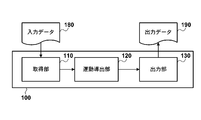
- the information processing apparatus 100 includes an acquisition unit 110, an exercise derivation unit 120, and an output unit 130.
- the acquisition unit 110 acquires input data 180 indicating the upper jaw model and the lower jaw model of the patient X, respectively.
- the input data 180 can be three-dimensional data.
- Various methods can be used as a three-dimensional data acquisition method.
- the information processing apparatus according to the present embodiment may include a photographing unit (not shown). When the imaging unit images the upper jaw and lower jaw of the patient, the acquisition unit 110 can acquire three-dimensional data indicating the upper jaw model and the lower jaw model, respectively.
- This imaging means may be able to directly capture a 3D image.
- 3M ESPE C.I. O. S chair side oral scanner
- There are similar products from other companies such as DICO Corporation, 3D System Japan, Nikon, Konica Minolta, Image Instruments, Exocad.
- the 3D photo of the face is also important, and you can use Image Instruments software.
- this photographing means may photograph a two-dimensional image. In this case, the two-dimensional image photographed by the photographing means is converted into three-dimensional data by a known method. This conversion may be performed by conversion means (not shown) included in the information processing apparatus according to the present embodiment.
- this conversion may be performed by a conversion device independent of the information processing apparatus according to the present embodiment.
- a conversion device independent of the information processing apparatus according to the present embodiment.
- this two-dimensional image for example, an X-ray photograph, a cephalo, a dental CT, a dentition panoramic photograph, an optical scanning (this is an apparatus (currently a 3-shape apparatus) having an accuracy of 14 microns). Can be used, but is not limited thereto. Any two-dimensional image that can be converted into three-dimensional data representing the upper jaw model and the lower jaw model is sufficient.
- the acquisition unit 110 may acquire the above-described two-dimensional data or three-dimensional data from the outside.
- the user may input the above-described two-dimensional data or three-dimensional data to the acquisition unit 110.
- the acquisition unit 110 may acquire the above-described two-dimensional data or three-dimensional data by receiving it from an independent device.
- the above-described two-dimensional data or three-dimensional data may be received from a remote device through a communication line.
- the remote device may be an image capturing device or a computer provided in a dental clinic.
- the upper jaw model and the lower jaw model acquired by the acquisition unit 110 may be represented by parameters.
- This parameter may be a parameter indicating the structure of at least one of the upper jaw and the lower jaw of the patient X individual.
- parameters used in Hobo S, Takayama H: Oral Rehabilitation clinical determination of Occlusion, 1997. Quintessence Publishing Co, Inc. can be used as this parameter.
- the acquisition unit 110 may calculate such parameters from the above-described two-dimensional data or three-dimensional data.
- the motion deriving unit 120 derives an eccentric motion between the upper jaw model and the lower jaw model using the three-dimensional data indicating the upper jaw model and the lower jaw model acquired by the acquisition unit 110, respectively.
- the eccentric motion derived by the motion deriving unit 120 may be an eccentric motion according to a standard cusp inclination angle. From the electronic measurement and kinematic analysis, it is known that the factor of molar separation is composed of the condyle path, the incisal path, and the cusp inclination angle. It has been found that the cusp tilt angle has little variation among individuals. Therefore, it can be said that the eccentric motion according to the standard cusp inclination angle is a standard (ideal) eccentric motion with little variation among individuals.
- Eccentric movement is a general term for the forward, lateral, and backward movements of the mandibular dental arch with respect to the maxillary bone, particularly the maxilla.
- the eccentric movement includes movement backward, laterally or forward from the intercuspal position, and particularly includes forward sliding movement and lateral sliding movement.
- the cusp fitting position refers to the position when the upper and lower teeth are fitted with the maximum contact area.
- Side movement is classified into working side movement and non-working side movement.
- the reason for using the cusp inclination angle is to discover the three elements of condylar tract, incisor tract, and cusp inclination angle, as shown above, in order to reproduce the amount of molar distraction associated with the birth of Takayama's theoretical formula. is there.
- the inclination angle of the cusp has very little variation and is about four times as reliable as the condylar path with blur and the incisal path with variation. That is, the inclination angle of the cusp is considered to be the expansion angle of the tooth.
- the shape of the condyle path, anterior teeth, and molars can be reproduced from the theoretical formula of mandibular movement, and the amount of molar separation can be reproduced by reproducing the anterior teeth and molars separately. Furthermore, since the functions of the incisor guidance plate and the bowl-shaped table can be reproduced, the angular form of the teeth (the cusp inclination angle and the incisal path angle) can be reproduced. Proven in occlusal color atlases and in vivo in vitro clinical findings in English books.
- the eccentric motion may be derived by using another method, for example, taking jaw motion by an axiograph, the check bite method, the Gotzic arch method, or the like.
- the following theoretical formula (1) is referred to as an ITH mandibular movement theoretical formula.
- Theoretical formula (1) is important as an indispensable condition for the development of virtual articulator software, including the new theoretical formula described above in the claims.
- the jaw movement with three axes and six degrees of freedom is expressed as translational movement in the (X, Y, Z) axis direction and rotational movement ( ⁇ , ⁇ , ⁇ ) around the origin. can do.
- Theoretical formula (1) is a theoretical formula representing the mandibular movement. Below, Formula (1) is demonstrated.
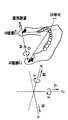
- a coordinate system fixed to the upper jaw is set with the front-rear direction as the X axis (front +), the left-right direction as the Y axis (right +), and the up-down direction as the Z axis (lower +).
- the displacement of an arbitrary point of the lower jaw in the three-dimensional space can be expressed by six movements of a three-dimensional sliding translation and a three-dimensional rotation.
- the mandibular movement is roughly divided into two movements, the forward movement and the lateral movement, and is classified into four in total, from the so-called proper central position to the movement in the front area and the movement in the rear area.
- the intersection of the intercondylar axis and the median plane is the origin
- the condylar center on the working side before the movement is the origin.
- Side motion includes right side motion and left side motion. Since these motions are symmetrical on the median plane, the right side motion is analyzed.
- the rotation angle in the XY plane is ⁇ (rad)
- the rotation angle in the YZ plane is ⁇ (rad)
- the rotation angle with the intercondylar axis as the rotation axis is ⁇ (rad). .
- the front-rear direction is the X axis
- the left-right direction is the Y-axis
- the up-down direction is the Z-axis.
- the front, right, and bottom are the positive directions, respectively. That is, the XY plane is a horizontal plane, the YZ plane is a frontal plane, and the ZX plane is a sagittal plane.
- one point of the lower jaw is the origin O of the motion coordinate system, and the coordinate axes (x, y, z) of the motion coordinate system are parallel to the coordinate axes (X, Y, Z) of the reference coordinate system.
- the three-dimensional displacement of the origin O after performing the motion including the translational motion and the rotational motion of the lower jaw is defined as ( ⁇ Ox, ⁇ Oy, ⁇ Oz).
- ⁇ is the radian display of the angle that the y-axis of the movement coordinate system makes with the Y-axis in the XY plane after the mandibular movement (the clockwise direction when viewed from the front is positive).
- ⁇ is a radians display of the angle that the y axis makes with the Y axis in the YZ plane (the clockwise direction when viewed from the front is positive).
- ⁇ be the radian display of the angle at which the zx plane rotates around the y-axis after the rotations ⁇ and ⁇ (the clockwise direction as viewed from the right is positive). The above definition is shown in FIG.
- the forward movement theoretical formula (1-1) representing the movement of the jaw in front of the center position occlusion or the cusp fitting position (forward movement region), and the posterior position of the cusp fitting position
- the backward movement theory formula (1-2) representing the movement of the jaw in the backward movement area
- jaw movements in the forward movement area and the backward movement area can be derived. That is, according to the forward movement theory formula (1-1), from the upper jaw model and lower jaw model of the patient X or parameters representing them, the jaw movement actually performed by the patient X in the forward movement area, that is, the central occlusion or the cusp It can be derived that the lower dental arch is moving forward from the fitting position (second calculation method).
- the jaw movement actually performed by the patient X in the backward movement region that is, the central occlusion or It can be derived that the lower dental arch is moving backward from the intercuspal position (first calculation method).
- the intersection M between the intercondylar axis and the median plane is the origin of the motion coordinate system. Further, in the lateral motion type, the condylar center C, C ′ on the working side is set as the origin.
- the forward motion in the anterior region is a hinge rotational motion that rotates about the intercondylar axis as a rotational axis and a positive parallel motion in the X-axis and Z-axis directions.
- ⁇ is as follows when the direction of opening the mouth is set to +.
- tan ⁇ cl ⁇ Zcl / ⁇ Xcl
- ⁇ l tan ⁇ cl ⁇ ⁇ l + ( ⁇ Xwl ⁇ tan ⁇ cl ⁇ Zwl) / Lc
- tan ⁇ il ⁇ Zil / ⁇ Yil Than
- ⁇ hl ( ⁇ l / Ai) ⁇ ((Ci ⁇ tan ⁇ cl + Ai + Lc ⁇ tanBe) ⁇ tan ⁇ il ⁇ (Lc / 2) ⁇ tan ⁇ cl)
- ⁇ Ywl (Lc ⁇ ⁇ l + ⁇ X
- ⁇ Xmp -1.558592329
- ⁇ Zmp 1.928362829
- 51.05324 ⁇ hl ⁇ 0.0221825621
- ⁇ Xmw 0.4052117727
- the motion deriving unit 120 can derive the eccentric motion including the Bennett motion according to the Bennett motion reproduction theoretical formula.
- the horizontal reference plane is the Axis plane. This can be applied to other planes. If the horizontal reference plane is changed, all angles in the sagittal plane and the X and Z coordinates are affected. For each angle in the sagittal plane, it is sufficient to subtract only the angle ⁇ formed with the axis plane.
- a conversion method for the X coordinate and the Z coordinate is described below.
- FIG. 11 shows the intersection of the Axis plane and the other plane.
- the condyle (C) is set to the origin of the Axis plane and the other plane, and the angle formed by ⁇ is set to ⁇ .
- the X and Z coordinates of the molar (M), incisor (I), and saddle (G) on the axis plane are (40, 40), (80, 40), and (120, 60), respectively, the axis plane
- the angle between the straight line CM and the straight line CM was found to be 45 °, and the angle made with the straight line CIG was found to be 26.5 °. From this, the X and Z coordinates on the other plane are obtained as follows.
- X ′ M 40 ⁇ 2 ⁇ cos (45 + ⁇ )
- Z ′ M 40 ⁇ 2 ⁇ sin (45 + ⁇ )
- X ′ I 40 ⁇ 5 ⁇ cos (26.5 + ⁇ )
- Z ′ I 40 ⁇ 5 ⁇ cos (26.5 + ⁇ )
- X ′ G 60 ⁇ 5 ⁇ cos (26.5 + ⁇ )
- X ′ G 60 ⁇ 5 ⁇ sin (26.5 + ⁇ )
- FIG. 7 shows the saddle-like and condylar displacements as seen from the sagittal plane.
- C1 is a position before movement of the condyle
- G1 is a position before movement of the saddle shape
- G2 is a point moved from G1 by ⁇ 7.1 mm in the X-axis direction and by ⁇ 7.1 mm in the Z-axis direction.
- the condyle moved from C1 by -7.8 mm in the X-axis direction and by -6.2 mm in the Z-axis direction (this point is referred to as C2).
- Coordinates (X'c1, Z'c1) and (X'g1, Z'g1) in other planes are obtained from the application of the ITH mandibular movement theory formula to other planes.
- X′c2, Z′c2, X′g2, and Z′g2 are obtained as follows.
- X ′ C2 X ′ C1 ⁇ 10 ⁇ cos (40 ⁇ )
- Z ′ C2 Z ′ C1 ⁇ 10 ⁇ sin (40 ⁇ )
- X ′ G2 X ′ G1 ⁇ 10 ⁇ cos (45 ⁇ )
- Z ′ G2 Z ′ G1 ⁇ 10 ⁇ sin (45 ⁇ )
- the numerical values obtained from this are as follows.
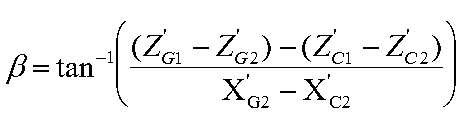
- FIG. 12 shows the condylar and saddle-like displacements as seen from the sagittal plane.
- G′1 is an intersection of lines drawn from G2 parallel to the Z axis and from C2 parallel to the X axis.
- G′2 is a point moved from G′1 by the same amount as the Z component from G1 to G2. From this, ⁇ is obtained as follows.
- ITH mandibular movement theory formula In applying ITH mandibular movement theory to other planes, it must be calculated once considering all angles such as sagittal angle and Bennett angle. The calculation results when this is not considered and when it is considered are described below.
- the X and Z coordinates in the condylar, incisor, and saddle-shaped planes are as shown above. (The coordinate value of the Y coordinate is unchanged even if the reference plane changes.) The sagittal plane angle is converted back to the axis plane for comparison.
- the X and Z coordinates change, and the Y coordinate does not change, so all values such as the sagittal plane, frontal plane, horizontal plane angle, and Bennett angle in each plane change.
- the sagittal plane angle ( ⁇ cp, ⁇ ip, ⁇ gp, ⁇ cl), frontal plane angle ( ⁇ il), and Bennett angle (Be) must be calculated with values appropriate for each plane. I must. The values so far were values on the axis plane. In order to utilize the ITH mandibular movement theory for other planes, the following calculations must be made and the respective values must be used.
- the sagittal plane angle ( ⁇ ′) on the other plane may be obtained by adding the angle ⁇ formed by the axis plane and the plane to the sagittal plane angle ( ⁇ ) of the axis plane.
- the Bennett angle will be described separately.
- the values of Condition 1 and Condition 2 are as follows.
- the positional relationship between the twin hobby articulator's incisal pole and saddle-shaped table is reproduced 40mm forward and 20mm downward vertically from the lower incisor, and the forward distance from the center of the condylar path is 120 It is a millimeter.
- the distance between the faces is set to 80 mm, so it is necessary to reproduce the middle of 40 mm in the articulator.
- the twin stage method that divides the model for the procedure of dividing the anterior and posterior teeth into two parts is the upper and lower teeth by pindex Since the height of the division is insufficient, the nurse has slid the upper bow frame of the articulator 20 mm upward. There is no problem in the calculation of the theory of motion. That is, it is manufactured as an articulator that standardizes the position of the condyle center point to 80 mm from the incisal path. Next, since the front reference point 43 mm reproduces the incisal edge of the maxillary right middle incisor, the maxillary occlusal plane is reproduced below 2.15 °.
- the occlusal plane is generally based on the lower dental arch, it is necessary to consider an angular difference of 3 mm on the overbite and overjet.
- the maxillary central incisor is 3 mm from the mandibular central incisor (corresponding to a theoretical condyle movement distance of 3 mm).
- the angle at the front of 83 mm is 2.07 °.
- the difference of 2 ° in the front is the virtual occlusal plane, the value of 45 ° subtracting 2 ° from the result of the paper of Angle Class I crowd that the incision road is not affected by the occlusal plane from the result of 47 ° on the Frankfurt plane. It becomes the angle in.
- the difference between the saddle shape and the condylar tract angle is calculated by calculating the misalignment angle of the articulator of the 120 mm upper arch about 10 mm virtual movement is roughly the angle of the Frankfurt plane with respect to the Axis plane (7.35). )) Is moved 10 millimeters on the condylar path angle (40 °) of the upper arch frame as it is, and is moved substantially in parallel. In other words, we decided to perform arithmetic on the occlusal plane reproduced as another standard. Similarly, the standard occlusal plane (see Table 8-5 of occlusion studies P.194) that is generally used has almost no effect on the incisal tract angle.
- the angle of the mandibular movement theory of Takayama is about 2 ° below the front reference point 3mm, and the angle to the Frankfurt plane from the calculation of the virtual occlusal plane is not affected by the occlusal plane. However, if it is 47 °, it can be reproduced as a value 45 ° reduced by 2 °.
- the ridge and the articulator arch are reversed 180 °, so the incisal tract angle is slid to the ridge angle and moved 120 mm on the condylar tract for the same distance.
- the difference between the condyle angle of 40 ° and the saddle angle of 45 ° is 5 ° (Macoris is clinically the difference between the condyle angle and the incisor angle is 5 °. Standardized to be reproduced without any influence of the occlusal plane even if the angles with respect to all the reference planes are traced to a twin hobby / zero hobby articulator, etc. ing. Moreover, the same result is obtained even if the same virtual movement is performed at 5.3 ° in the previous case. Furthermore, in general clinical practice, the range of guidance of the articulator exceeds 10 mm, and the entire jaw dentition is adjusted while guiding the teeth.
- the above-mentioned 2.1 °, approximately 2 ° is subtracted from the incisal road angle to obtain the incisal road angle at the Frankfurt plane.
- the angle below the forward reference point 3 mm below the altitude of the mandibular movement theory of the alpine is about 2 °
- the angle to the Frankfurt plane from the calculation of the virtual occlusal plane is not affected by the occlusal plane. If the road angle is 47 °, it can be reproduced as 45 ° reduced by 2 °.
- the incisal tract angle is 45 ° when the saddle angle is 45 °
- the condylar tract angle is 40 °
- the anterior reference point is 43 mm.
- the articulator is determined to be defined as 45 °.
- the late Dr. Takayama also stated that a physical difference of about 1 ° is fuzzy and corresponds to ambiguity. In other words, this is the angle that is reproduced on the twin hobby articulator.
- the current incision angle 45 ° is specified. However, this is the reason why it has a good clinical growth effect.
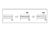
- the upper and lower tooth rows viewed from the sagittal plane are represented by rectangles for the sake of simplicity.
- a sprint having a width of 1.5 mm is put on the upper and lower teeth, and the hatched portion is scraped.
- the coordinates after the movement of the incisor and condyle when the second molar is raised 1.5 mm are as follows.
- the jaw movement actually performed by the patient X can be derived. it can.
- the motion deriving unit 120 can derive the eccentric motion according to the theoretical formula of the virtual articulator reproduction and the theoretical formula of the process of regenerating the internal jaw.
- POSTUROGRAFIA equipment suggested clues to solve these problems.
- POSTUGRAFIA diagnoses the relevance of multiple elements that support human balance, and also considers Retinianas, sensory factors, eye movement elements Propioceptivas, Oculomotrices, etc.
- the output unit 130 outputs information indicating the eccentric motion derived by the motion deriving unit 120 as output data 190.
- Various methods can be adopted as the output method of the output unit 130.
- the output unit 130 can output a moving image indicating the eccentric motion between the upper jaw and the lower jaw.
- the output unit 130 may output a moving image indicating a forward motion or a lateral motion while contacting the teeth.
- the motion in the forward motion region may be shown, or the motion in the backward motion region may be shown.
- the information output by the output unit 130 is not limited to a moving image, and a still image according to the eccentric motion derived by the motion deriving unit 120 may be output. Further, the image generated by the output unit 130 may be a two-dimensional image or a three-dimensional image.
- the output unit 130 can output image data by various methods. For example, the image output unit 130 can display image data via a display (not shown). The image output unit 130 may store image data in a storage medium via an input / output device (not shown). Furthermore, when the acquisition unit 110 acquires data from an external device, the image output unit 130 may transmit the image data to the external device.
- the information output from the output unit 130 may be a parameter indicating the nature of the eccentric motion derived by the motion deriving unit 120.
- parameters used in Hobo S, Takayama H: Oral Rehabilitation clinical determination of Occlusion, 1997. Quintessence Publishing Co, Inc. can be used as this parameter.
- the motion deriving unit 120 may derive a parameter indicating the jaw motion actually performed by the patient X instead of deriving the jaw motion (eccentric motion) itself.
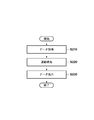
- FIG. 2 is a flowchart illustrating processing performed by the information processing apparatus 100.
- step S210 the acquisition unit 110 acquires the input data 180 as described above.
- step S220 the motion deriving unit 120 derives the eccentric motion between the upper jaw model and the lower jaw model as described above.
- step S230 the output unit 130 outputs output data 190 indicating the eccentric motion derived by the motion deriving unit 120.
- the motion deriving unit 120 derives the eccentric motion between the upper jaw and the lower jaw using the upper jaw model and the lower jaw model of the patient X.
- the upper jaw model and lower jaw model of patient X it is not necessary to use the upper jaw model and lower jaw model of patient X as they are.
- a user such as a dentist can also perform operations such as deformation on the upper jaw model and the lower jaw model. This operation includes, for example, changing the tooth shape and moving each tooth.
- the upper jaw model and the lower jaw model after the operation is performed by the user may be input to the information processing apparatus 100 as the input data 180.
- the acquisition unit 110 may correct the upper jaw model and the lower jaw model indicated by the acquired input data 180 in response to an instruction from the user.
- the information processing apparatus 101 according to the second embodiment can compare the eccentric movement between the upper jaw and the lower jaw with an arbitrary jaw movement of the patient.
- An information processing apparatus according to the present embodiment is shown in FIG. 1B. Similar to the information processing apparatus 100 according to the first embodiment, the information processing apparatus 101 according to the present embodiment includes an acquisition unit 110, an exercise derivation unit 120, and an output unit 130.
- the acquisition unit 110 and the motion deriving unit 120 according to the present embodiment operate in the same manner as in the first embodiment.
- the output unit 130 operates in the same manner as in the first embodiment except that the comparison result of the comparison unit 150 is output. For this reason, description about the acquisition part 110, the exercise
- the information processing apparatus 101 may include the reproducing unit 140.
- the reproducing unit 140 can reproduce and reproduce the eccentric motion between the upper jaw and the lower jaw of the patient X using the upper jaw three-dimensional model and the lower jaw three-dimensional model acquired by the acquisition unit 110.
- the construction and reproduction of jaw movement can be performed by various methods.
- the playback unit 140 may acquire a moving image obtained by imaging the jaw movement of the patient X via the acquisition unit 110. By analyzing this moving image, the actual jaw movement of the patient X can be derived.
- the jaw movement of the patient X can be reproduced by moving the upper jaw three-dimensional model and the lower jaw three-dimensional model in accordance with the derived jaw movement.
- the eccentric motion reproduced / reproduced by the reproducing unit 140 may be a standard motion (standard motion) according to a standard cusp inclination angle.
- the reproduction unit 140 can reproduce and reproduce the standard movement between the upper jaw and the lower jaw by applying a standard cusp inclination angle to the above-described forward motion theory formula and backward motion theory formula. it can.
- the cusp inclination angles of different cusp inclined surfaces can be applied, and thus the movement in the forward movement area or the movement in the backward movement area can be calculated.
- different cusp tilt angles can be applied when deriving forward motion and when deriving lateral motion.
- different cusp inclination angles can be applied to the working side and the non-working side in the lateral movement.
- the working side refers to the side that is chewed by the back teeth of the molar portion, and the cusp inclined surface of the tooth slides on the working side.
- the side opposite to the working side is referred to as the non-working side.
- the fixed dental arch side can also be called the working side.
- the moving side of the opposite condylar path is called the non-working side, and it can be said that the lower dental arch is moving from the non-working side to the working side.
- the applied cusp angle does not have to be the same for all teeth (all molars), and a different cusp angle unique to each tooth can be applied.
- diagnosis consisting of evidence-based dentistry, it is important to take into account the average factor. With the backing of this scientific basis, the ITH mandibular movement theory formula can derive the jaw movement.
- the applied cusp angle can be determined based on, for example, an average value.
- an average value of the cusp inclination angle for a plurality of people can be used.
- an average value for each patient attribute can also be used.
- the inclination angle of the sagittal plane in the forward movement of the first molar is 43 °
- the inclination angle of the frontal surface on the working side in the lateral movement is 25 °
- the inclination angle of the non-working frontal surface in lateral movement may be 34 °.
- the inclination angle of the sagittal plane in the forward movement of the second molar is 43 °
- the inclination angle of the frontal surface on the working side in the lateral movement is 25 °
- the inclination angle of the frontal surface on the non-working side in the lateral movement is It can be 35 °.
- the inclination angle of the sagittal plane in the forward movement of the upper second molar can be 47 °
- the inclination angle of the sagittal plane in the lateral movement can be 40 °.
- the angle of the occlusal surface of one tooth can also be calculated as a pinpoint angle from the ITH theoretical formula.
- the eccentric motion reproduced by the reproducing unit 140 is compared with the eccentric motion derived by the motion deriving unit 120, the eccentric motion of the jaw of the patient X corresponding to the standard eccentric motion derived by the motion deriving unit 120 is reproduced. It is preferable to reproduce. That is, the eccentric motion derived by the motion deriving unit 120 and the eccentric motion reproduced by the reproducing unit 140 are preferably the same type of motion.
- the same type of motion can be, for example, motion in substantially the same direction, or motion in substantially the same region.
- the motion deriving unit 120 derives the motion in the forward motion region
- the playback unit 140 also reproduces the motion in the forward motion region.
- the reproducing unit 120 also reproduces and reproduces the lateral motion.
- the reproducing unit 140 may acquire an instruction for movement between the upper jaw and the lower jaw from a user such as a dentist.
- the user can give any instruction that indicates the patient's jaw movement.
- the reproducing unit 140 may display the upper jaw three-dimensional model and the lower jaw three-dimensional model acquired by the acquisition unit 110 to the user.
- the user can freely move the three-dimensional model of the upper jaw and the lower jaw while looking at the displayed three-dimensional model.
- the user can reproduce the eccentric motion between the upper jaw and the lower jaw of the patient X.
- the angle of the cusp inclined surface of each tooth can be set using the ITH mandibular movement theory. In other words, a better tempo-cervical environment can be reproduced by setting the cusp inclination angle for various jaw movements.
- the angle of the occlusal surface of one tooth can also be calculated as a pinpoint angle from the ITH theoretical formula.
- the information processing apparatus 101 further includes a comparison unit 150.
- the comparison unit 150 can compare the eccentric motion derived by the motion deriving unit 120 with the standard motion between the upper jaw and the lower jaw.
- the standard exercise may be an eccentric exercise preset by the user, for example.
- an eccentric motion reproduced / reproduced by the reproducing unit 140 may be used as the reference motion. That is, the comparison unit 150 may compare the eccentric motion derived by the motion deriving unit 120 and the eccentric motion reproduced / reproduced by the reproduction unit 140.
- the comparison unit 150 compares the eccentric motion derived by the motion deriving unit 120 with the eccentric motion reproduced / reproduced by the reproduction unit 140 will be described.
- the comparison unit 150 compares the eccentric motion derived by the motion deriving unit 120 with a preset eccentric motion.
- the comparison can be done by various methods. For example, the movement distances of the exercises may be compared, and the directions of the exercises may be compared. In this case, it is good also as a comparison result whether exercise
- the comparison unit 150 compares the eccentric motion derived by the motion deriving unit 120 with the eccentric motion set in advance or reproduced / reproduced by the reproduction unit 140 for each of the forward motion region and the backward motion region. It is preferable. Further, the comparing unit 150 compares the eccentric motion derived by the motion deriving unit 120 with the eccentric motion set in advance or reproduced / reproduced by the reproducing unit 140 for each of the forward motion and the lateral motion. Is preferred.
- the state of contact with the inclined surfaces of the upper and lower jaws can be determined by deleting or constructing the contact site of each tooth covered when the lower dental arch itself moves according to the theoretical formula. You can also compare exercises based on procedures. For example, it is determined whether or not each tooth is in contact with each of the eccentric motion derived by the motion deriving unit 120 and the eccentric motion reproduced by the reproducing unit 140. Teeth come in contact with and move away with movement. Therefore, the order in which the teeth come in contact, the order in which the teeth move away, or both may be determined. If this order matches between the eccentric motion derived by the motion deriving unit 120 and the eccentric motion reproduced and reproduced by the playback unit 140, information indicating that the order matches can be output. . If the order is different, information indicating that the order is different may be output, and information indicating which tooth is different in order may be output.
- the evaluation of the contact state of the teeth as described above can also be performed by using the ITH mandibular movement theoretical formula shown in the first embodiment.
- the reproduction unit 140 may compare movements using a well-known comparison unit for jaw movements.
- the comparison unit 150 may cause the output unit 130 to output both the eccentric motion derived by the motion deriving unit 120 and the eccentric motion reproduced by the reproduction unit 140. In this case, the user can compare both eccentric motions.
- the comparison unit 150 uses the parameter derived by the motion deriving unit 120 and the reference value. May be compared.
- This reference value may be determined in advance based on an average purpose. In other words, an average value of parameters indicating jaw movement obtained from clinically measured jaw movement data for a plurality of persons can be used as the reference value.
- the reference value is preferably a parameter indicating jaw movement according to a reference (average) cusp inclination angle.
- the reference value may be a value determined in advance by the user as a parameter indicating ideal exercise.
- the reference value may be a value set corresponding to the patient's attributes (gender, age, etc.).
- the reference value may be an average value of parameters indicating jaw movement for each patient attribute (gender, age, etc.).
- the acquisition unit 110 may acquire patient attributes as part of the input data 180, and the comparison unit 150 may acquire a reference value corresponding to the patient attributes acquired by the acquisition unit 110.
- the comparison unit 150 acquires this reference value.
- This reference value may be stored in the reproduction unit 140, for example. That is, the reproducing unit 140 may output a parameter indicating the average jaw movement to the comparison unit 150 instead of reproducing the average jaw movement. But the comparison part 150 may acquire this reference value from a user.
- the comparison unit 150 outputs a comparison result between the parameter derived by the motion deriving unit 120 and the reference value.
- the comparison unit 150 may output the difference between the parameter derived by the motion deriving unit 120 and the reference value.
- the comparison unit 150 may compare the difference between the parameter derived by the motion deriving unit 120 and the reference value with a predetermined threshold value. In this case, the comparison unit 150 may output information indicating whether the difference is larger than a predetermined threshold value or smaller than the predetermined threshold value, that is, whether there is almost no difference.
- the comparing unit 150 may compare each parameter with a corresponding reference value.
- the comparison unit 150 may output information indicating which parameter is deviated from the reference value. Whether or not a parameter deviates from the reference value can be determined by comparing the difference between the parameter and the reference value with a predetermined threshold value.
- the comparison unit 150 preferably compares the parameter derived by the motion deriving unit 120 with the reference value for each of the forward motion region and the backward motion region. Furthermore, it is preferable that the comparison unit 150 compares the parameter derived by the motion deriving unit 120 with the reference value for each of the forward motion and the lateral motion. Further, different reference values may be set for the forward motion area and the backward motion area, or different reference values may be set for the forward motion and the lateral motion. Furthermore, in the lateral movement, parameters indicating jaw movement may be obtained independently for the working side and the non-working side. In this case, different reference values may be set for the working side and the non-working side, and each parameter may be compared with the corresponding reference value.
- 7D leads from the identification of the cause and the prevention method to the treatment method, and predicts the result.
- 8D is a measure for transmitting the result to a sensory receptor that is the patient's own five senses based on the prediction.
- the diagnostic policy for treatment is taken in and the treatment policy is positioned.
- the five-dimensional function that reproduces the temporal change of the eccentric motion in the past, the present, and the future, and how the situation progressed in the past to the present.
- Such a function can be realized by the ITH comprehensive plan maxillofacial motion theoretical formula as shown above or by a program including this theoretical formula.
- FIG. 3 shows a computer 500 according to the present embodiment.
- the computer 500 includes a CPU 510, a RAM 520, a ROM 530, a storage device 540, an I / F (network interface) 550, an input device 560, and an output device 570.
- the computer 500 may include other elements not shown.
- the computer 500 according to the present embodiment may be a home personal computer, a television that displays a television image, or a tablet computer such as iPad (registered trademark). It may be a server.
- the CPU 510 controls the operation of the entire computer 500.
- the CPU 510 can operate according to a program stored in the RAM 520 or the ROM 530.
- the RAM 520 can temporarily store data and programs.
- the ROM 530 is a nonvolatile memory, and can store a program necessary for operating the computer 500, for example.
- the storage device 540 may be a device that stores data and programs. Further, the storage device 540 may be a device that reads stored data and programs.
- the storage device 540 includes, for example, a hard disk, a CD drive, a DVD drive, and the like.
- the I / F 550 is an interface for connecting the computer 500 according to the present embodiment to the network 580.
- the computer 500 according to this embodiment can access the network 580 via the I / F 550.
- the computer 500 according to the present embodiment can transmit and receive data to and from other devices via the I / F 550 and the network 580.
- the input device 560 is a device for giving instructions to the computer 500 by the user.
- the input device 560 includes, for example, a keyboard and a mouse.
- the output device 570 is a device for the computer 500 to present information to the user.
- the output device 570 includes a display and a printer.
- the functions of the above-described embodiments may be expressed by a computer program and the computer program may be executed by the computer 500.
- this computer program is loaded into the RAM 520 via the storage device 540 or the I / F 550.
- a computer program stored in a storage medium such as a CD-ROM can be installed in a storage device 540 that is a hard disk via a storage device 540 that is a CD-ROM drive.
- the computer program on the network 580 can be installed in the storage device 540 that is a hard disk via the I / F 550.
- the computer program on the storage device 540 that is a hard disk can be loaded into the RAM 520.
- the CPU 510 can control the computer 500 according to the computer program loaded into the RAM 520.
Landscapes
- Health & Medical Sciences (AREA)
- Oral & Maxillofacial Surgery (AREA)
- Life Sciences & Earth Sciences (AREA)
- Dentistry (AREA)
- Epidemiology (AREA)
- Animal Behavior & Ethology (AREA)
- General Health & Medical Sciences (AREA)
- Public Health (AREA)
- Veterinary Medicine (AREA)
- Engineering & Computer Science (AREA)
- General Engineering & Computer Science (AREA)
- Physics & Mathematics (AREA)
- Theoretical Computer Science (AREA)
- Computer Hardware Design (AREA)
- Evolutionary Computation (AREA)
- Geometry (AREA)
- General Physics & Mathematics (AREA)
- Biomedical Technology (AREA)
- Biophysics (AREA)
- Dental Tools And Instruments Or Auxiliary Dental Instruments (AREA)
- Dental Prosthetics (AREA)
- Measurement Of The Respiration, Hearing Ability, Form, And Blood Characteristics Of Living Organisms (AREA)
Abstract
Description
患者の上顎及び下顎を表す三次元モデルを取得する取得手段と、
前記取得手段により取得された前記上顎を表す三次元モデルと前記取得手段により取得された前記下顎を表す三次元モデルとの間の偏心運動を導出する導出手段と、
を備え、
前記導出手段は、咬頭嵌合位よりも後方の前記偏心運動を導出することを特徴とする。
1.歯科治療の眞の診断となる基準は、全世界どこにも存在していない。
2.総合治療手段の真髄であるCAD・CAM機器には、情報伝達ソフト遺伝子の欠落がある。
3.エビデンス・ベースド・デンティストリー(眞の診断)とアルゴリズム(個人情報の調和)のいずれを選択するのか、両者合い見回ることにより、医療の場との頂点と基盤とを構築する。
4.個人情報を活用することは重要であるが、本来あるべき真理となるCADとして認識されるのであろうか。本発明者は永久歯の段階で将来の展望を予測してきて20数年間になる。
5.科学的な総合企画理論式「ITH下顎運動理論式」を活用して、歯科医師が誠の決断を下すための、治療のための結果決断から診断のためになる方法論を、本発明は全世界に提供する。
ΔX=-B×δ-C×Θ+ΔOx
ΔY= C×γ+A×δ+ΔOy
ΔZ= A×Θ-B×γ+ΔOz
[前方運動理論式(1-1)]
ΔX= B×δ-C×Θ+ΔOx
ΔY= C×γ+A×δ+ΔOy
ΔZ= A×Θ+B×γ+ΔOz
Ωcp:前方運動において顆頭間軸中点の運動軌跡が矢状面内で水平基準面となす傾斜角(左右の矢状前方顆路傾斜角の平均)
Λcp:平均前方顆路長(√((ΔXcp,ave)2+(ΔZzp,ave)2):三平方)
Δcl:側方顆路長(√(ΔXcl2+ΔYcl2+ΔZcl2))
ΔXcp,ave:左右顆頭中心の前方変位の平均(顆頭間軸中点の前方変位)
ΔZcp,ave:左右顆頭中心の下方変位の平均(顆頭間軸中点の下方変位)
ΔXwl:作業側顆頭中心の前方変位
ΔYwl:作業側顆頭中心の側方変位(ただし右側方運動のときは右を正、左側方運動のときは左を正)
ΔZwl:作業側顆頭中心の下方変位
ΔXil:切歯点の前方変位
ΔYil:切歯点の側方変位(ただし右側方運動のときは右を正、左側方運動のときは左を正)
ΔZil:切歯点の下方変位
Ωcp=tan-1(ΔZcp,ave/ΔXcp,ave):前方運動において顆頭間軸中点の運動軌跡が矢状面内で水平基準面となす傾斜角(左右の矢状前方顆路傾斜角の平均)
Ωcl=tan-1(ΔZcl/ΔXcl):側方運動において非作業側の顆路が矢状面内で水平基準面となす傾斜角(矢状側方顆路傾斜角)
Be=tan-1(ΔYcl/ΔXcl):側方運動において非作業側の顆路が水平面内で矢状面となす傾斜角(ベネット角、または水平側方顆路角)
Ωip=tan-1(ΔZip/ΔXip):前方運動において切歯路が矢状面内で水平基準面となす傾斜角(矢状前方切歯路傾斜角)
Ωil=tan-1(ΔZil/ΔXil):側方運動において切歯路が矢状面内で水平基準面となす傾斜角(矢状側方切歯路傾斜角)
Φil=tan-1(ΔZil/ΔYil):側方運動において切歯路が前頭面内で水平基準面となす傾斜角(前頭側方切歯路傾斜角)
Ψil=tan-1(ΔYil/ΔXil):側方運動において切歯路が水平面内で矢状面となす角(水平側方切歯路角、またはゴツィック・アーチ角)
Θhp:前方運動における顆頭間軸(y軸)の回りの回転角のラジアン表示:前方運動におけるΘ(前方蝶番回転角)
Θhl:側方運動における顆頭間軸(y軸)の回りの回転角のラジアン表示:側方運動におけるΘ(側方蝶番回転角)
δl:側方運動における作業側顆頭中心を通り顆頭間軸と非作業側顆路とを含む面に垂直な軸の回りの回転角の水平面投影のラジアン表示:側方運動におけるδ(水平側方回転角)
γl:側方運動における作業側顆頭中心を通り顆頭間軸と非作業側顆路とを含む面に垂直な軸の回りの回転角の前頭面投影のラジアン表示:側方運動におけるγ(前頭側方回転角)
Lc:左右の顆頭中心C,C’間の距離:顆頭間軸C-C’の長さ(顆頭間距離)
(Ai,Bi,Ci):切歯点の運動座標系における3次元座標
を表す。また、前方運動式においては顆頭間軸と正中面との交点Mを運動座標系の原点とする。さらに、側方運動式においては作業側の顆頭中心C,C’を原点とする。これらの点については図4に示されている。
前方領域(前方運動理論式)での前方運動は顆頭間軸を回転軸としてその周りに回転する蝶番回転運動とX軸,Z軸方向にプラスの平行移動の運動である。前方運動では、左右の変位はないとみなすためΔY=0とおいて解析を進める。よって基本式においてδ=0,γ=0,δOy=0と置くことと同値である。また、Θは口が開く方向を+と設定すると、以下のようになる。
ΔX=-C×Θhp+ΔOx
ΔY=0
ΔZ= A×Θhp+ΔOz
ΔX= cosΩcp×Λcp-C×Θhp
ΔZ= sinΩcp×Λcp+A×Θhp
tanΩip=ΔZip/ΔXip
よりΘhpを求めると、
Θhp=((tanΩip-tanΩcp)×cosΩcp×Λcp)/(Ci×tanΩip+Ai)
と求まる。
側方運動は作業側の顆頭中心を中心としたX-Y平面の回転運動、Y-Z平面の回転運動と蝶番回転運動の3次元の回転運動と、顆頭の3次元の滑走平行移動(ΔXwl,ΔYwl,ΔZwl)の運動であり、下記のように表せる。
ΔX= B×δl -C×Θhl +ΔXwl
ΔY= C×γl +A×δl +ΔYwl
ΔZ= A×Θhl +B×γl +ΔZwl
δl=(ΔXcl-ΔXwl)/Lc=(Λcl×cosΩcl)/Lc
γl=(ΔZcl-ΔZwl)/Lc
となり、
tanΩcl=ΔZcl/ΔXcl
より、
γl=tanΩcl×δl+(ΔXwl×tanΩcl-ΔZwl)/Lc
また、
tanΦil=ΔZil/ΔYil
より、
Θhl=(δl/Ai)×((Ci×tanΩcl+Ai+Lc×tanBe)×tanΦil-(Lc/2)×tanΩcl)
が求まり、他に
ΔYwl=(Lc×δl+ΔXwl)×tanBe
が得られる。(ΔXwl,ΔZwlは測定により求める。測定できない場合は0として計算する。)
ΔΔX=-A×((δl2+Θh2)/2)-C×δlγl/2
ΔΔY= B×((δl2+γl2)/2)+A×γlΘh-C×δlΘh
ΔΔZ=-C×((γl2+Θh2)/2)-A×δlγl/2
ΔX=-B×δ-C×Θ+ΔOx
ΔY= C×γ-A×δ+ΔOy
ΔZ= A×Θ+B×γ+ΔOz
後方運動理論式(1-2)からも、前方運動を表す式(1-2-1)と、側方運動(右側方運動及び左側方運動)を表す式(1-2-2)とを導くことができる。
後方領域の前方運動は前方運動理論式の運動と比べると、蝶番回転運動は同じで口が開く方向が+と設定してあるが、滑走平行移動についてはX軸は-、Z軸は+の方向に動くので以下のようになる。
ΔX=-cosΩcp×Λcp-C×Θhp
ΔZ= sinΩcp×Λcp+A×Θhp
Θhp=((tanΩip-tanΩcp)×cosΩcp×Λcp)/(Ai-Ci×tanΩip)
後方運動は前方領域の運動と比べると、X-Y平面内での回転δが逆方向に回転する。そのため、Y軸に平行な滑走平行移動ΔYwlも前方運動理論式のそれとは逆の方向に移動すると考える。他の滑走平行移動の2つと回転の2つの動きは前方運動理論式と同じであるから前方運動理論式の式においてδl→-δl、ΔYwl→-ΔYwlに変換すればよい。よって以下のようになる。(前方領域と同じようにδl、γl、2次微小項も求めた。)
ΔY= C×γl -A×δl +ΔYwl
ΔZ= A×Θhl+B×γl +ΔZwl
δl=(ΔXcl-ΔXwl)/Lc=(Λcl×cosΩcl)/Lc
γl=tanΩcl×δl-(ΔXwl×tanΩcl+ΔZwl)/Lc
Θhl=(δl/Ai)×((Ci×tanΩcl-Ai-Lc×tanBe)×tanΦil-(Lc/2)×tanΩcl)
ΔYwl=-(Lc×δl+ΔXwl)×tanBe
ΔΔX=-A×((δl2+Θh2)/2)+C×δlγl/2
ΔΔY= B×((δl2+γl2)/2)+A×γlΘh+C×δlΘh
ΔΔZ=-C×((γl2+Θh2)/2)+A×δlγl/2
ΔX=-Bδ-CΘ
ΔZ=Cγ-Aδ+ΔYwl
ΔZ=Bγ+AΘ
Θhp=-9.244262507×10⁻³
ΔXmp=-1.558592329
ΔZmp=1.928362829
Ωmp=51.05324
Θhl=-0.0221825621
ΔXmw=0.4052117727
ΔYmw=-0.3822412627
ΔZmw=-0.3127691477
ΔXmnw=-0.5589696418
ΔYmnw=-0.3822412627
ΔZmnw=0.836297517
Φmw=29.69135211
Φmnw=51.00212093
この算出法は以下のように、まずアキシス平面上で非作業側の顆頭の変位を算出し、それを他平面から見た座標に変換し、高山の理論式を用いてBe角を算出する。図5及び図6は、この算出方法を示す。まず基準となるアキシス平面で高山の理論式から非作業側の顆頭の座標を求める。
ΔYwl=ΔXwl×tanBe=Lc×δl×tanBe
ΔZwl=Lc×γ
より、
ΔXwl=2.29
ΔYwl=0.61
ΔZwl=1.92
が得られる(アキシス平面でのBe角は15°)。座標と図6からX軸とOAのなす角が約40°と求められ、各平面でのx’、Be角を求める式が以下のようになった。
x’=OAcos(40+α)
Be=tan-1(ΔYwl/x’)

咬合器には様々な基準平面を用いたものがあり、また、咬合器において樋状傾斜角度と顆路傾斜角度の差をマコーリス(McHorris)は、5°という値が臨床的に良いと報告している。これについて仮想の咬合器を想定して顆頭と樋状か移動した際の変位量を以下のようにして調べる。

X’M=40√2×cos(45+α)
Z’M=40√2×sin(45+α)
X’I=40√5×cos(26.5+α)
Z’I=40√5×cos(26.5+α)
X’G=60√5×cos(26.5+α)
X’G=60√5×sin(26.5+α)

X’C2=X’C1-10×cos(40-α)
Z’C2=Z’C1-10×sin(40-α)
X’G2=X’G1-10×cos(45-α)
Z’G2=Z’G1-10×sin(45-α)
これより求まった数値は以下のような結果である。


ITH下顎運動理論式を他平面に用いるにあたって、矢状面の角度、ベネット角など、あらゆる角度について一度考慮して計算しなければならない。これを考慮しなかった場合と考慮した場合の計算結果を以下に記す。なお、顆頭、切歯、樋状の各平面でのX,Z座標は、上に示した通りである。(Y座標は基準平面が変わっても座標の数値は不変である。)また、矢状面角度は比較のためにアキシス平面に変換し直した。


アングル1級叢生の抜歯、非抜歯症例からの論文からも述べられているように、仮にフランクフルト平面に対してのU1―L1の角度47°は、実際どのように関係しているかを以下に列挙していく。
顎内症の歯牙の誘導については第2臼歯を1.5mm高くすると切歯は3mm前方に移動し、臼歯は3mm下方に移動する。これについて、第2臼歯を高くしたことによる下顎への(誘導の)影響について調べる。これにより、顎内症患者について第2臼歯を高くする方法で治療するときに何mm高くすればよいか目安がわかるようになる。以下の方法で理論式を導いた。
θ=tan-1(Z/40)=tan-1(1.5/40)=2.14°
と求まった。
X’=X×cosθ-Z×sinθ+3
Z’=X×sinθ+Z×cosθ+1.5

実施例1において運動導出部120は、患者Xの上顎モデル及び下顎モデルを用いて、上顎と下顎との間の偏心運動を導出した。しかしながら、患者Xの上顎モデル及び下顎モデルをそのまま用いる必要はない。例えば歯科医師のようなユーザは、上顎モデル及び下顎モデルに対して、変形などの操作を加えることもできる。この操作には、例えば歯の形状を変えること、及びそれぞれの歯を移動させることが含まれる。
運動導出部120が顎運動そのものを導出するのではなく、患者Xが実際に行っている顎運動を示すパラメータを導出する場合、比較部150は、運動導出部120が導出したパラメータと、基準値とを比較してもよい。この基準値は、平均的な趣旨に基づいて予め決定されていてもよい。すなわち、臨床的に測定された複数人についての顎運動データから求められる、顎運動を示すパラメータの平均値を、この基準値として用いることができる。特にこの基準値は、基準的(平均的)な咬頭傾斜角に従う顎運動を示すパラメータであることが好ましい。もっともこの基準値は、理想的な運動を示すパラメータとして予めユーザによって決定された値であってもよい。
Claims (10)
- 患者の上顎及び下顎を表す三次元モデルを取得する取得手段と、
前記取得手段により取得された前記上顎を表す三次元モデルと前記取得手段により取得された前記下顎を表す三次元モデルとの間の偏心運動を導出する導出手段と、
を備え、
前記導出手段は、咬頭嵌合位よりも後方の前記偏心運動を導出することを特徴とする情報処理装置。 - 前記導出手段は、第1の計算方法を用いて咬頭嵌合位よりも後方の前記偏心運動を導出し、前記第1の計算方法とは異なる第2の計算方法を用いて咬頭嵌合位よりも前方の前記偏心運動を導出することを特徴とする、請求項1に記載の情報処理装置。
- 前記導出手段により導出された偏心運動と、予め設定された運動とを比較する比較手段をさらに備えることを特徴とする、請求項1に記載の情報処理装置。
- 咬頭嵌合位よりも後方の前記偏心運動は、下式
ΔX=-B×δ-C×Θ+ΔOx
ΔY= C×γ-A×δ+ΔOy
ΔZ= A×Θ+B×γ+ΔOz
(上式において、(ΔOx,ΔOy,ΔOz)は下顎の一点を運動座標系(x,y,z)の原点Oとする場合の下顎運動後の原点Oの三次元変位であり、δは該下顎運動後に運動座標系のy軸がX-Y面内でY軸となす角のラジアン表示であり、γは該下顎運動後にy軸がY-Z面内でY軸となす角のラジアン表示γであり、Θは回転δ及びγが行われたあとz-x面がy軸の周りに回転する角のラジアン表示であり、(ΔX,ΔY,ΔZ)は下顎上の座標(A,B,C)にある点の三次元変位である)
に従って導出されることを特徴とする、請求項1乃至3の何れか1項に記載の情報処理装置。 - 前記導出手段は、ベネット運動の再現理論式に従ってベネット運動を含む前記偏心運動を導出することを特徴とする、請求項1乃至4の何れか1項に記載の情報処理装置。
- 前記導出手段は、バーチャル咬合器再現の理論式及び顎内障の再現過程の理論式に従って前記偏心運動を導出することを特徴とする、請求項1乃至5の何れか1項に記載の情報処理装置。
- 過去・現在・未来の前記偏心運動の経時的変化を再現する5次元の機能と、過去において状況がどのように進行して現在に至ったのか原因を特定して現在から将来への予防方法を診断する6次元の機能と、前記原因の特定及び前記予防方法に従って治療方法を提示し該治療方法による結果の予測を行う7次元の機能と、該結果の予測に従って患者自身の五感である感覚受容器への伝達方法を提示する8次元の機能と、を実現することを特徴とする、請求項1乃至6の何れか1項に記載の情報処理装置。
- 情報処理装置が行う情報処理方法であって、
患者の上顎及び下顎を表す三次元モデルを取得する取得工程と、
前記取得工程で取得された前記上顎を表す三次元モデルと前記取得工程で取得された前記下顎を表す三次元モデルとの間の偏心運動を導出する導出工程と、
を含み、
前記導出工程では、咬頭嵌合位よりも後方の前記偏心運動を導出することを特徴とする情報処理方法。 - コンピュータを、請求項1乃至7の何れか1項に記載の情報処理装置が有する各手段として機能させるためのプログラム。
- ITH総合企画顎顔面運動理論式を包括することを特徴とする、請求項9に記載のプログラム。
Priority Applications (3)
| Application Number | Priority Date | Filing Date | Title |
|---|---|---|---|
| KR1020137006047A KR101482167B1 (ko) | 2010-08-10 | 2011-07-27 | 정보 처리 장치, 정보 처리 방법 및 기록 매체 |
| EP11816218.9A EP2604220A4 (en) | 2010-08-10 | 2011-07-27 | INFORMATION PROCESSING DEVICE, INFORMATION PROCESSING PROCESS AND PROGRAM |
| US13/763,049 US20130151208A1 (en) | 2010-08-10 | 2013-02-08 | Information processing apparatus, information processing method, and program |
Applications Claiming Priority (4)
| Application Number | Priority Date | Filing Date | Title |
|---|---|---|---|
| JP2010-179639 | 2010-08-10 | ||
| JP2010179639 | 2010-08-10 | ||
| JP2011-060242 | 2011-03-18 | ||
| JP2011060242A JP5676325B2 (ja) | 2010-08-10 | 2011-03-18 | 情報処理装置、情報処理方法、及びプログラム |
Related Child Applications (1)
| Application Number | Title | Priority Date | Filing Date |
|---|---|---|---|
| US13/763,049 Continuation US20130151208A1 (en) | 2010-08-10 | 2013-02-08 | Information processing apparatus, information processing method, and program |
Publications (1)
| Publication Number | Publication Date |
|---|---|
| WO2012020548A1 true WO2012020548A1 (ja) | 2012-02-16 |
Family
ID=45567524
Family Applications (1)
| Application Number | Title | Priority Date | Filing Date |
|---|---|---|---|
| PCT/JP2011/004252 WO2012020548A1 (ja) | 2010-08-10 | 2011-07-27 | 情報処理装置、情報処理方法、及びプログラム |
Country Status (5)
| Country | Link |
|---|---|
| US (1) | US20130151208A1 (ja) |
| EP (1) | EP2604220A4 (ja) |
| JP (1) | JP5676325B2 (ja) |
| KR (1) | KR101482167B1 (ja) |
| WO (1) | WO2012020548A1 (ja) |
Cited By (3)
| Publication number | Priority date | Publication date | Assignee | Title |
|---|---|---|---|---|
| CN102626348A (zh) * | 2012-04-19 | 2012-08-08 | 大连理工大学 | 一种仿下颌运动机器人 |
| WO2016013359A1 (ja) * | 2014-07-22 | 2016-01-28 | 有限会社 メディコム | コンピュータ、コンピュータで実行される方法、及びコンピュータプログラム、並びにフェイスボウ |
| US20210106403A1 (en) * | 2019-10-15 | 2021-04-15 | Dommar LLC | Apparatus and methods for orthodontic treatment planning |
Families Citing this family (16)
| Publication number | Priority date | Publication date | Assignee | Title |
|---|---|---|---|---|
| US20130204600A1 (en) * | 2012-02-06 | 2013-08-08 | Tarun Mehra | Virtual articulator |
| CN104869940B (zh) | 2012-10-18 | 2017-11-07 | 3形状股份有限公司 | 多个咬合配置 |
| DK2908767T3 (en) * | 2012-10-18 | 2019-03-25 | 3Shape As | SYSTEM AND PROCEDURE FOR DESIGNING A DENTAL COMPONENT |
| US9737257B2 (en) | 2015-01-30 | 2017-08-22 | 3M Innovative Properties Company | Estimating and predicting tooth wear using intra-oral 3D scans |
| KR101802917B1 (ko) * | 2016-05-04 | 2017-11-29 | 주식회사 메디트 | 치아 움직임 추적 장치 및 그 방법 |
| MX2019002375A (es) | 2016-08-31 | 2019-09-05 | Lucas Kelly | Sistema y metodo para producir soluciones dentales incorporando un paquete de guia. |
| JP6285002B1 (ja) * | 2016-11-30 | 2018-02-28 | 益弘 古川 | 顎関節症等歯科疾患治療のためのシステム及びプログラム |
| WO2018107293A1 (en) * | 2016-12-16 | 2018-06-21 | Cumulus Dental Incorporated | Method and system for creating a customizable dental chart |
| CN108113780B (zh) * | 2018-02-06 | 2020-11-10 | 北京大学口腔医学院 | 用于下颌骨髁假体制作的下颌骨髁运动轨迹测量方法 |
| CA3131694A1 (en) | 2019-03-26 | 2020-10-01 | Kjeld A. AAMODT | Methods and systems for orthodontic treatment planning |
| US11000349B2 (en) * | 2019-06-05 | 2021-05-11 | Dentsply Sirona Inc. | Method, system and computer readable storage media for determining articulation parameters |
| CN111476905B (zh) * | 2020-04-04 | 2023-11-21 | 哈尔滨理工大学 | 一种基于增强现实的机器人辅助牙体预备仿真系统 |
| US20220023006A1 (en) * | 2020-07-22 | 2022-01-27 | Clearcorrect Operating, Llc | Mandibular repositioning appliances and methods of manufacturing the same |
| WO2022075698A2 (ko) * | 2020-10-06 | 2022-04-14 | 이우형 | 상하악 치열의 악궁 형태 및 교합 양상을 분류한 빅데이터 클라우드를 기반으로 한 악궁 형태, 교합양상을 분석할 수 있고, 해부학적 이상적인 위치에 상하악 치열이 병합될 수 있는 시스템 |
| WO2023009732A1 (en) * | 2021-07-28 | 2023-02-02 | Visionx, Llc | Computer-implemented method and system for tooth setup |
| WO2023069837A1 (en) * | 2021-10-18 | 2023-04-27 | CVSTOM Co. | Methods and systems for orthodontic treatment planning with virtual jaw articulator |
Citations (7)
| Publication number | Priority date | Publication date | Assignee | Title |
|---|---|---|---|---|
| JP2004136072A (ja) * | 2002-08-22 | 2004-05-13 | Hidefumi Ito | 歯科用咬合器 |
| JP2007037687A (ja) | 2005-08-02 | 2007-02-15 | Hidefumi Ito | 歯科診療支援方法及びシステム |
| WO2008149221A1 (en) * | 2007-06-08 | 2008-12-11 | Align Technology, Inc. | Treatment planning and progress tracking systems and methods |
| JP2010506692A (ja) | 2006-10-20 | 2010-03-04 | スリーエム イノベイティブ プロパティズ カンパニー | デジタル歯科矯正治療計画 |
| JP2010524529A (ja) * | 2007-04-18 | 2010-07-22 | マテリアライズ・デンタル・ナムローゼ・フエンノートシャップ | 顔面解析を用いた特注歯セットアップのコンピュータ支援作成 |
| JP2010179639A (ja) | 2009-02-09 | 2010-08-19 | Akiyama International Kk | オフセット印刷機の版万力装置 |
| JP2011060242A (ja) | 2009-09-14 | 2011-03-24 | Ricoh Co Ltd | プログラムダウンロードシステム、プログラムダウンロード方法、画像形成装置、プログラム配信サーバおよびダウンロードプログラム |
Family Cites Families (15)
| Publication number | Priority date | Publication date | Assignee | Title |
|---|---|---|---|---|
| JPH09238963A (ja) * | 1996-03-07 | 1997-09-16 | Nikon Corp | 顎運動のシミュレーション方法 |
| AUPO280996A0 (en) * | 1996-10-04 | 1996-10-31 | Dentech Investments Pty Ltd | Creation and utilization of 3D teeth models |
| US6450807B1 (en) * | 1997-06-20 | 2002-09-17 | Align Technology, Inc. | System and method for positioning teeth |
| US6152731A (en) * | 1997-09-22 | 2000-11-28 | 3M Innovative Properties Company | Methods for use in dental articulation |
| US20090148486A1 (en) * | 2005-04-28 | 2009-06-11 | Helen Lu | Compositions and methods for treating pulp inflammations caused by infection or trauma |
| KR100854634B1 (ko) * | 2006-11-29 | 2008-08-27 | 강릉대학교산학협력단 | 3차원 역공학 기술을 이용한 치아 이동 자동측정 방법 |
| WO2009011345A1 (ja) * | 2007-07-17 | 2009-01-22 | Motonori Munehiro | 下顎位決定方法、下顎位決定装置、プログラムおよび咬合器 |
| JP5390377B2 (ja) * | 2008-03-21 | 2014-01-15 | 淳 高橋 | 三次元デジタル拡大鏡手術支援システム |
| US8199988B2 (en) * | 2008-05-16 | 2012-06-12 | Geodigm Corporation | Method and apparatus for combining 3D dental scans with other 3D data sets |
| US20100183523A1 (en) * | 2009-01-22 | 2010-07-22 | Wagner Richard E | Dental composition and method |
| US8896592B2 (en) * | 2009-08-21 | 2014-11-25 | Align Technology, Inc. | Digital dental modeling |
| US20110247214A1 (en) * | 2010-04-08 | 2011-10-13 | Specialty Appliance Works, Inc. | Methods for forming progressive aligners |
| US20110318709A1 (en) * | 2010-06-25 | 2011-12-29 | Takeshi Moriyama | Artificial tooth |
| EP3348229B1 (en) * | 2011-11-15 | 2020-03-11 | Trispera Dental Inc. | Method and system for acquiring data from an individual for preparing a 3d model |
| US20130204600A1 (en) * | 2012-02-06 | 2013-08-08 | Tarun Mehra | Virtual articulator |
-
2011
- 2011-03-18 JP JP2011060242A patent/JP5676325B2/ja not_active Expired - Fee Related
- 2011-07-27 KR KR1020137006047A patent/KR101482167B1/ko active Active
- 2011-07-27 WO PCT/JP2011/004252 patent/WO2012020548A1/ja active Application Filing
- 2011-07-27 EP EP11816218.9A patent/EP2604220A4/en not_active Withdrawn
-
2013
- 2013-02-08 US US13/763,049 patent/US20130151208A1/en not_active Abandoned
Patent Citations (7)
| Publication number | Priority date | Publication date | Assignee | Title |
|---|---|---|---|---|
| JP2004136072A (ja) * | 2002-08-22 | 2004-05-13 | Hidefumi Ito | 歯科用咬合器 |
| JP2007037687A (ja) | 2005-08-02 | 2007-02-15 | Hidefumi Ito | 歯科診療支援方法及びシステム |
| JP2010506692A (ja) | 2006-10-20 | 2010-03-04 | スリーエム イノベイティブ プロパティズ カンパニー | デジタル歯科矯正治療計画 |
| JP2010524529A (ja) * | 2007-04-18 | 2010-07-22 | マテリアライズ・デンタル・ナムローゼ・フエンノートシャップ | 顔面解析を用いた特注歯セットアップのコンピュータ支援作成 |
| WO2008149221A1 (en) * | 2007-06-08 | 2008-12-11 | Align Technology, Inc. | Treatment planning and progress tracking systems and methods |
| JP2010179639A (ja) | 2009-02-09 | 2010-08-19 | Akiyama International Kk | オフセット印刷機の版万力装置 |
| JP2011060242A (ja) | 2009-09-14 | 2011-03-24 | Ricoh Co Ltd | プログラムダウンロードシステム、プログラムダウンロード方法、画像形成装置、プログラム配信サーバおよびダウンロードプログラム |
Non-Patent Citations (7)
| Title |
|---|
| "Science of Occlusion", 1995, QUITESSENCE PUBLISHING CO., INC. |
| HIDEFUMI ITO; TOSHIO TAKAYAMA, SCIENCE OF OCCLUSION, vol. 24, no. 1, 2004, pages 81 |
| HOBO S; TAKAYAMA H: "Oral Rehabilitation clinical determination of Occlusion", 1997, QUINTESSENCE PUBLISHING CO., INC. |
| HOBO S; TAKAYAMA H: "Oral Rehabilitation clinical determination of Occlusion", 1997, QUITESSENCE PUBLISHING CO., INC. |
| MICHIO HAGA ET AL., TOSHIO TAKAYAMA, KOGOGAKU, 1ST EDITION, 10 January 1995 (1995-01-10), pages 564 - 566, XP008171754 * |
| See also references of EP2604220A4 * |
| TAKAYOSHI KAWAZOE: "Clinical Evidence and Prosthodontics", JOURNAL OF PROSTHETIC DENTISTRY, vol. 46, 2002, pages 476 |
Cited By (5)
| Publication number | Priority date | Publication date | Assignee | Title |
|---|---|---|---|---|
| CN102626348A (zh) * | 2012-04-19 | 2012-08-08 | 大连理工大学 | 一种仿下颌运动机器人 |
| WO2016013359A1 (ja) * | 2014-07-22 | 2016-01-28 | 有限会社 メディコム | コンピュータ、コンピュータで実行される方法、及びコンピュータプログラム、並びにフェイスボウ |
| JP2016022228A (ja) * | 2014-07-22 | 2016-02-08 | 高橋 淳 | コンピュータ、コンピュータで実行される方法、及びコンピュータプログラム、並びにフェイスボウ |
| US20210106403A1 (en) * | 2019-10-15 | 2021-04-15 | Dommar LLC | Apparatus and methods for orthodontic treatment planning |
| US11793605B2 (en) * | 2019-10-15 | 2023-10-24 | 3D Smile Usa, Inc. | Apparatus and methods for orthodontic treatment planning |
Also Published As
| Publication number | Publication date |
|---|---|
| JP2012055680A (ja) | 2012-03-22 |
| JP5676325B2 (ja) | 2015-02-25 |
| EP2604220A1 (en) | 2013-06-19 |
| US20130151208A1 (en) | 2013-06-13 |
| EP2604220A4 (en) | 2015-08-12 |
| KR20130041323A (ko) | 2013-04-24 |
| KR101482167B1 (ko) | 2015-01-14 |
Similar Documents
| Publication | Publication Date | Title |
|---|---|---|
| JP5676325B2 (ja) | 情報処理装置、情報処理方法、及びプログラム | |
| US20250040874A1 (en) | Three Dimensional Imaging of the Motion of Teeth and Jaws | |
| US11633265B2 (en) | Dynamic virtual articulator for simulating occlusion of teeth | |
| US11772331B2 (en) | System and method for producing dental solutions incorporating a guidance package | |
| RU2567604C2 (ru) | Динамический виртуальный артикулятор | |
| EP2408394B1 (en) | System for planning, visualization and optimization of dental restorations | |
| KR101590330B1 (ko) | 형상 정보를 얻기 위한 방법 | |
| CN106137414B (zh) | 确定目标牙列布局的方法和系统 | |
| CN114126535B (zh) | 正畸与牙科处理规划中的虚拟关节运动 | |
| WO2012140021A2 (en) | Modeling and manufacturing orthodontic appliances | |
| PL235136B1 (pl) | Sposób rejestracji ruchu i geometrii stawu skroniowo-żuchwowego | |
| JP2022509164A (ja) | 修正された顎間関係における患者の下顎及び上顎のアーチのモデルをアニメーション化する方法 | |
| KR20220005874A (ko) | 환자 맞춤형 어버트먼트 디자인 방법 및 그 장치 | |
| CN119136726A (zh) | 监测咬合变化的方法 | |
| Patel et al. | Surgical planning: 2D to 3D | |
| JP2004129890A (ja) | 歯科用人工物製作時において人工歯列弓の最前方点を決定する装置 | |
| US20240382287A1 (en) | Systems and methods for generating and scoring teeth aligner setups using computer-based digital dental models | |
| Alghauli et al. | Clinical eHealth | |
| Lin et al. | Virtual Articulators | |
| EP3216010A1 (en) | Three dimensional imaging of the motion of teeth and jaws | |
| HK1243298A1 (zh) | 用於建模患者下颌运动学的方法和系统 | |
| HK1243298B (en) | Method and system for modeling the mandibular kinematics of a patient |
Legal Events
| Date | Code | Title | Description |
|---|---|---|---|
| 121 | Ep: the epo has been informed by wipo that ep was designated in this application |
Ref document number: 11816218 Country of ref document: EP Kind code of ref document: A1 |
|
| NENP | Non-entry into the national phase |
Ref country code: DE |
|
| ENP | Entry into the national phase |
Ref document number: 20137006047 Country of ref document: KR Kind code of ref document: A |
|
| REEP | Request for entry into the european phase |
Ref document number: 2011816218 Country of ref document: EP |
|
| WWE | Wipo information: entry into national phase |
Ref document number: 2011816218 Country of ref document: EP |