以下に、本発明の実施例1に係る情報処理装置について説明する。本実施例によれば、情報処理装置上で顎運動を再現することができる。本実施例に係る情報処理装置は、バーチャル咬合器の機能を有するCAD・CAMシステムでありうる。従来技術において、咬合器の機能を情報処理装置上で再現するバーチャル咬合器は存在した。しかしながら、咬合器の機能自体だけで再現できる患者の顎運動は限られている。したがって、従来技術のバーチャル咬合器では、患者の顎運動を高い精度で再現し、診断の資料として利用することはできなかった。したがって、既存のバーチャル咬合器(CAD・CAM)で咬合状態を再現することは、歯科医療の診断資料としては不十分であった。
Hereinafter, the information processing apparatus according to the first embodiment of the present invention will be described. According to the present embodiment, jaw movement can be reproduced on the information processing apparatus. The information processing apparatus according to the present embodiment may be a CAD / CAM system having a virtual articulator function. In the prior art, there has been a virtual articulator that reproduces the function of the articulator on an information processing device. However, the patient's jaw movement that can be reproduced only by the function of the articulator is limited. Therefore, the virtual articulator of the prior art cannot reproduce the patient's jaw movement with high accuracy and use it as diagnostic data. Therefore, reproducing the occlusal state with an existing virtual articulator (CAD / CAM) is insufficient as a diagnostic material for dentistry.
バーチャル咬合器は、各社様々な咬合平面を基準として製作をしている。そのために各個人情報をスキャンニング、CT等から、2D、3Dに変換しながら物理シュミレーションを活用して、チェック・バイト、ゴシックアーチ、パントグラフ(例えば、アキシオ・グラフ等)を採得して顆路角、切歯路角を定めて補綴、矯正、義歯等を製作するのが現状のバーチャル・咬合器である。今回のITH下顎運動理論式は、企画化された請求項にあるベネット運動の理論式、各種咬合平面における角度等を表にまとめてある。そこで、各種咬合平面における顆路角、切歯路角、樋状角度、ベネット角を設定してある。また、高山の下顎運動理論式の条件1である、臼歯部の再現において偏心運動の後方歯牙の前方の移動を基準値に沿って製作することで、顎内障を発現してしまった。その経緯から、後方運動の再現が重要であると仮定して今回のITH下顎運動理論式が完成できたのである。さらに、顎内障の再現過程から理論式を導出した。これら、全て、個人情報と平均値的な診断としてのエビデンスとの比較をすることで、顎顔面運動の再現が可能となる。また、咬合平面から、高山の理論式は、アキシス平面を基準として数値化されている。また、前方基準点も理論式に取り込まれる数値である。アキシス平面の黄金分割比から、70ミリとしたときの前方基準点を43ミリに定めている。各個人によって、顔面の高さ、つまり、咬合高径は、異なるので、例えば80ミリと計測されれば、前方の高さは、算出できる。つまり、各個人情報を2D、3Dに置換すれば、個人のバーチャル咬合器が再現できることになる。これも、同様なことであって今回の理論式の平均値との比較で過去、現在、未来の展望を見定めることで、結果が判断されて治療方針が決定される総合企画診断プロセスと言える。このプロセスを図9に示す。
The virtual articulator is manufactured based on various occlusal planes of each company. For this purpose, each personal information is converted from scanning, CT, etc. to 2D, 3D, using physical simulation, and check bytes, Gothic arches, pantographs (eg, axio graphs, etc.) are obtained. The current virtual / articulator is used to manufacture prosthetics, orthodontic teeth, dentures, etc. by setting the road angle and the incisor road angle. This ITH mandibular movement theory formula is a table of Bennett movement theoretical formulas, angles in various occlusal planes, etc. in the planned claims. Therefore, the condyle path angle, incisor path angle, saddle-shaped angle, and Bennett angle in various occlusal planes are set. In addition, in the reproduction of the molar part, which is condition 1 of Takayama's mandibular movement theory formula, the movement of the posterior teeth of the eccentric movement was produced along the reference value in accordance with the reference value, and the internal jaw disorder was developed. From this background, the theoretical formula for ITH mandibular movement was completed, assuming that reproduction of backward movement is important. In addition, a theoretical formula was derived from the process of reproducing internal jaw disorders. All of these, by comparing personal information with evidence as an average diagnosis, it is possible to reproduce the maxillofacial movement. From the occlusal plane, Takayama's theoretical formula is quantified based on the Axis plane. The forward reference point is also a numerical value that is taken into the theoretical formula. From the golden section ratio of the Axis plane, the front reference point is set to 43 mm when it is 70 mm. The height of the face, that is, the occlusal height varies depending on the individual, and therefore the front height can be calculated if it is measured as 80 mm, for example. That is, if each personal information is replaced with 2D and 3D, a personal virtual articulator can be reproduced. This is also the same, and it can be said that it is a comprehensive planning diagnosis process in which the result is judged and the treatment policy is determined by determining the past, present, and future prospects by comparing with the average value of this theoretical formula. This process is illustrated in FIG.
従来の咬合器を用いた歯科診療においては、歯牙又は義歯は非常に審美的に作製され、患者に提供されることが求められた。特に健康保険適用外の材料を使用して作成される補綴物に関しては審美的であることが要求される。しかしながらこれらの歯牙又は義歯は、技工士による調整、例えばリマウントによる試行錯誤が必要であった。それにも関わらず口腔内に装着する際には歯科医師によって口腔内の調整が施工せざるを得ないことが、常であった。一方で本実施例に従って作製された歯牙又は義歯は、正確に口腔内に装着されうる。なぜなら、本実施例に係る情報処理装置は、患者の3軸6自由度の上下顎運動をより高い精度で再現することができ、さらに個々の歯牙の形態を考慮して顎運動を再現しうるからである。条件2の前歯部の数値を基準化すれば、審美的であって機能的な要素も包括されている。ただし、限界は、あるものの、その際に、顎矯正をすることから、動的、保定後の矯正完了後に最終の審美性を見極められる。さらには、義歯に必要なあらゆる材質に順ずる人工歯も製作が可能であり、個々人に適合させうる歯冠の形態も同様に製作可能である。ここでは通念として用いられる「審美的」との語を用いたが、これは醜いものを改善することを意味し、本来は、美しく綺麗になることを意味する「美容的」との語を用いるべきであることを付記する。
In dental practice using a conventional articulator, it was required that teeth or dentures be made very aesthetically and provided to patients. In particular, prosthetics made using materials not covered by health insurance are required to be aesthetic. However, these teeth or dentures require adjustment by a technician, for example, trial and error by remounting. In spite of this, when it was installed in the oral cavity, the oral cavity had to be adjusted by the dentist. On the other hand, the tooth or denture made according to the present embodiment can be accurately placed in the oral cavity. This is because the information processing apparatus according to the present embodiment can reproduce the patient's three-axis and six-degree-of-freedom mandibular movement with higher accuracy, and can reproduce the jaw movement in consideration of individual tooth forms. Because. If the value of the front tooth part of Condition 2 is standardized, aesthetic and functional elements are included. However, although there is a limit, since the jaw correction is performed at that time, the final aesthetics can be determined after completion of correction after dynamic and retention. Furthermore, artificial teeth conforming to all materials necessary for dentures can be manufactured, and a crown shape that can be adapted to an individual can be manufactured in the same manner. Here, the term “aesthetic” is used as a general rule, but this means improving the ugly things, and originally using the term “beauty”, which means beautiful and beautiful. Note that it should be.
すなわち、
1.歯科治療の眞の診断となる基準は、全世界どこにも存在していない。
2.総合治療手段の真髄であるCAD・CAM機器には、情報伝達ソフト遺伝子の欠落がある。
3.エビデンス・ベースド・デンティストリー(眞の診断)とアルゴリズム(個人情報の調和)のいずれを選択するのか、両者合い見回ることにより、医療の場との頂点と基盤とを構築する。
4.個人情報を活用することは重要であるが、本来あるべき真理となるCADとして認識されるのであろうか。本発明者は永久歯の段階で将来の展望を予測してきて20数年間になる。
5.科学的な総合企画理論式「ITH下顎運動理論式」を活用して、歯科医師が誠の決断を下すための、治療のための結果決断から診断のためになる方法論を、本発明は全世界に提供する。
That is,
1. There is no standard anywhere in the world for diagnosing dental sputum.
2. The CAD / CAM device, which is the essence of comprehensive treatment, has a lack of information transmission software genes.
3. By scrutinizing whether to choose between evidence-based dentistry (diagnosis of acupuncture) or algorithm (harmony of personal information), we will build the top and foundation of the medical field.
4). It is important to use personal information, but will it be recognized as CAD that is the truth that should be? The present inventor has predicted the future prospects at the permanent tooth stage, and it has been 20 years.
5. The present invention is a method that makes use of scientific comprehensive planning theory formula “ITH mandibular movement theory formula” to make diagnosis from the result decision for treatment for the dentist to make a sincere decision. To provide.
本実施例に係る情報処理装置は特に、顎運動プログラムを用いて、顎運動を再現しうる。例えば本実施例に係る情報処理装置は、顎運動プログラムが組み込まれたCADでありうる。本実施例に係る顎運動プログラムは、20年以上に亘って収集された臨床成績を解析した結果をもとにして、本発明者によって開発された。本実施例に係る顎運動プログラムは、理論式(方程式)の形で表現しうる。この理論式(ITH下顎運動理論式)は、高山下顎運動理論式(Hobo S, Takayama H: Oral Rehabilitation clinical determination of Occlusion, 1997. Quintessence Publishing Co, Inc., 咬合学, クインテッセンス社, 1995.)を再評価することにより構築された。また、このITH下顎運動理論式は、顎後方運動及び顎内障の発現過程を理論的に示す。
In particular, the information processing apparatus according to the present embodiment can reproduce jaw movement using a jaw movement program. For example, the information processing apparatus according to the present embodiment may be a CAD in which a jaw movement program is incorporated. The jaw movement program according to the present example was developed by the present inventor based on the result of analyzing clinical results collected over 20 years. The jaw movement program according to the present embodiment can be expressed in the form of a theoretical formula (equation). This theoretical formula (ITH mandibular movement theoretical formula) is derived from the Takayama mandibular movement theoretical formula (Hobo S, Takayama H: Oral Rehabilitation clinical determination of Occlusion, 1997. Quintessence Publishing Co, Inc. Built by reevaluation. In addition, this ITH mandibular movement theory formula theoretically shows the process of posterior jaw movement and internal jaw injury.
具体的には本発明者は、高山の下顎運動理論式における誤りを発見し、さらに後方運動領域における理論式を発見した。以下に修正点と修正理論式を提示していく。(1)Table.11 樋型調節性切歯指導板の側翼角の理論式から、水平側方切歯路角の投影角と実角を再現する算出式が存在しなかった。(2)Table.12 蝶番回転角の算出式の前方顆路角(誤Ωil→正Ωcp)と顆頭間距離(誤Lc、正 1/2Lc)代入に誤りが懸念された。(3)Table.13 咬頭路傾斜の算出式の蝶番回転角(誤Θtmp→正Θthp)が方程式に誤って代入されていることが発見された。(4)Table.17 樋状テーブルの切歯指導板にガイドされた咬合器の上顎フレームの蝶番回転角の算出式の顆路角(誤りΩcp→正Ωcl)が方程式に誤って代入されていることが発見された。
Specifically, the present inventor found an error in the alpine mandibular movement theory, and further discovered a theory in the backward movement region. The correction points and correction theory are presented below. (1) From the theoretical formula of the side wing angle of Table.11 vertical adjustable incisor guidance plate, there was no calculation formula to reproduce the projection angle and actual angle of the horizontal side incisor road angle. (2) There was a concern about errors in substitution of the anterior condylar path angle (error Ωil → positive Ωcp) and intercondylar distance (error Lc, positive ½Lc) in Table. (3) It was discovered that the hinge rotation angle (error Θtmp → positive Θthp) in Table. (4) The condyle path angle (error Ωcp → positive Ωcl) in the calculation formula of the hinge angle of the upper jaw frame of the articulator guided by the incisor guidance plate of Table. It was discovered.
過去20年間にわたる臨床成績結果が功を奏していたのは、高山が計算式を導出する前の膨大な資料と作図とから咬合器の寸法値と顎頭頚部の平均値を算出した結果に誤りが無かったためであった。ITH多次元構想理論式原案によって、高山の顎内障発現過程による作図を活用して問題を解消できた。また、ツインホビー咬合器による後方運動分析によって、いわゆる早期接触部位が、後方運動にとって重要性であることが確認できた。顆路以外のどこかで衝立のごとく保持しているという推論から、後方運動の要因が後方歯牙に起因することを発見した。こうして、多次元構想によるエビデンス・ベースド・デンティストリーを確立した。ここでは、ITH下顎運動理論式の有効性とバーチャル咬合器の実現可能性を示す。各個人の評価ポイントとする数値を計測することで、各個人のいわゆるバーチャル咬合器の再現も可能であり、平均値としての評価と比較できる。また、データ管理のもとで多次元構想が実現できる。
The results of the clinical results over the past 20 years have been successful because the results of calculating the size of the articulator and the average value of the temporomandibular neck from an enormous amount of data and drawings before Takayama derived the calculation formula are incorrect. It was because there was no. The draft of the ITH multi-dimensional concept theoretical formula has solved the problem by utilizing the drawing process of Takayama's internal jaw injuries. Moreover, it was confirmed that the so-called early contact portion is important for backward motion by backward motion analysis using a twin hobby articulator. From the reasoning that it was held like a screen somewhere other than the condylar path, we discovered that the factor of posterior movement was due to the posterior tooth. In this way, an evidence-based dentistry based on a multidimensional concept was established. Here, the effectiveness of the ITH mandibular movement theory and the feasibility of a virtual articulator are shown. By measuring the numerical value as the evaluation point of each individual, it is possible to reproduce the so-called virtual articulator of each individual, and it can be compared with the evaluation as an average value. In addition, a multidimensional concept can be realized under data management.
本実施例において例として用いられる顎運動プログラムは、個人の顔の大きさや顎の形状・長さなどの個人に特有のパラメータにしたがって、個人にとって最も快適な咬合が行える平均的な顎運動を再現しうる。再現された平均的な顎運動と患者との比較を、実際に患者の歯牙の形状・顎の矯正等を行うことなく、この顎運動プログラムは、歯科医師に患者の状態を診断しうる情報を提供できる。言い換えれば、この顎運動プログラムは、患者の総合的な診断を支援しうる。また、本実施例に係る情報処理装置は、空間軸及び時間軸を含む、4次元の診断資料を提供しうる。すなわち本実施例に係る情報処理装置は、患者の顎の3次元画像を提供するのに加え、時間軸に沿った3軸6自由度の上下顎運動を再現して提供しうる。平均的な顎運動、臨床エビデンス、及び快適な咬合の関係について、例えば川添尭彬氏は、「臨床エビデンスと歯科補綴学」(補綴誌、第46巻、476頁、2002年)において、次のように述べている。「可能な限り適切な臨床エビデンス(平均値的なデータ)を用いながら、個性的な個々の患者において、害のない適切な臨床診断を行うには、平均値的な臨床エビデンスに加えて医師の深遠なフィロソフィーや経験、さらに、医療資源、患者の嗜好等への配慮をも統合する高次の医療判断技術が含まれている。
The jaw movement program used as an example in this example reproduces the average jaw movement that allows the most comfortable occlusion for an individual according to individual parameters such as individual face size and jaw shape / length. Yes. Compared with the average jaw movement reproduced and the patient, this jaw movement program provides the dentist with information that can diagnose the patient's condition without actually correcting the patient's tooth shape and jaw. Can be provided. In other words, this jaw movement program can support a comprehensive diagnosis of the patient. Further, the information processing apparatus according to the present embodiment can provide four-dimensional diagnostic material including a space axis and a time axis. That is, the information processing apparatus according to the present embodiment can reproduce and provide a three-axis and six-degree-of-freedom mandibular movement along the time axis in addition to providing a three-dimensional image of the patient's jaw. Regarding the relationship between average jaw movement, clinical evidence, and comfortable occlusion, for example, Satoshi Kawazoe, in “Clinical Evidence and Dental Prosthesis” (Prosthetics, 46, 476, 2002) As stated. “In order to make a harmless and appropriate clinical diagnosis in an individual patient, using the best possible clinical evidence (average data), in addition to the average clinical evidence, It includes advanced medical judgment technology that integrates profound philosophy and experience, as well as considerations for medical resources, patient preferences, and the like.
本実施例によれば、3軸6自由度の顎関節運動が再現できる。また、歯牙咬頭傾斜角と咬頭路斜面の状態と接触状態変化を再現できる。本実施例によれば、人体(個体も)の顎運動自体をPC内で再現できる。(既存の技術は、顎運動を患者の外部で再現する咬合器の動きをPC内で再現したもので、咬合器の動き自体には再現する限界が存在する。)また、以下に示すように、ITH顎運動理論が発見された。これらの特徴は、ITH下顎運動理論式が完成したことと、バーチャルで上顎、下顎歯列を再現する技術を応用することによって実現可能となる。本実施例によれば、PC内で、人体の顎運動の再現と合わせて咬合理論、診断理論などの顎運動を加えることで診断材料を歯科医師が受け取れる。(従来では、咬合器を使用して診断するための技術と知識が技術者に必要とされた。)
According to the present embodiment, the temporomandibular joint motion with three axes and six degrees of freedom can be reproduced. Moreover, the state of the tooth cusp inclination angle, the state of the cusp road slope, and the contact state change can be reproduced. According to the present embodiment, the jaw movement itself of a human body (including an individual) can be reproduced in the PC. (Existing technology reproduces the movement of the articulator that reproduces the jaw movement outside the patient in the PC, and there is a limit to reproduce the movement of the articulator itself.) ITH jaw movement theory was discovered. These characteristics can be realized by completing the theoretical formula of ITH mandibular movement and applying a technique for virtually reproducing the maxillary and mandibular dentition. According to the present embodiment, a dentist can receive diagnostic materials by applying jaw movements such as occlusion theory and diagnostic theory together with reproduction of human jaw movements in a PC. (Traditionally, technicians needed skill and knowledge to diagnose using an articulator.)
ITH下顎運動理論式は、3次元CT等による表記された寸法値を導出することで、各歯牙の咬頭傾斜面の形状を精確に作成可能である。つまり、各歯牙メーカーから販売されている人工歯を標準であるかの判定もできる。その違いをも精査できる特徴を兼ね備えている。
The ITH mandibular movement theory formula can accurately create the shape of the inclined surface of the cusp of each tooth by deriving the dimension value expressed by 3D CT or the like. In other words, it is possible to determine whether the artificial teeth sold by each tooth manufacturer are standard. It also has the feature that can scrutinize the difference.
以下に本実施例に係る情報処理装置について説明するが、用いられうる情報処理装置は以下で説明するものに限られない。例えば、患者の3軸6自由度の上下顎運動をより高い精度で再現すること、本実施例に係る顎運動プログラム(CAD)を用いること、などの以下に説明する特徴を、既存のバーチャル咬合器の可動特性に合わせて適用してもよい。アキシス平面を基準とする計算からすべてのバーチャル咬合器に連動可能である。
The information processing apparatus according to the present embodiment will be described below, but the information processing apparatus that can be used is not limited to the one described below. For example, the features described below, such as reproducing the patient's 3-axis 6-degree-of-freedom mandibular movement with higher accuracy, and using the jaw movement program (CAD) according to the present embodiment, the existing virtual occlusion You may apply according to the movable characteristic of a vessel. All virtual articulators can be linked from the calculation based on the Axis plane.
また上述のような、3軸6自由度の顎運動を数値化して4次元までのシミュレーションを行うシステムは、歯牙咬頭傾斜角を再現することにより、上下歯牙の斜面の形状と接触状態の差異及び変化を構築できるシステムと、統合することもできる。例えばAutodesk(SoftImage)、3-Shape、カボデンタルシステム、セレック、プロセラ、セルコン、エンジェルクラウン、インセラム、ウワルセラム、エベレスト、Image Instruments、他日本のメーカーなどが販売している物理シミュレーションシステムと統合することができる。また、本実施例に係る情報処理装置は例えばサーバであってもよく、クライアント装置と通信回線で接続されうる。この場合、クライアント装置は、MRA、MAI、CT、スキャニングされた視覚映像等によって得られた画像を、本実施例に係る情報処理装置に送信することができる。また、本実施例に係る情報処理装置は、クライアント装置から送信された画像を用いて後述のような処理を行い、処理結果をクライアント装置に送信することもできる。
In addition, the system for simulating the jaw movement with three axes and six degrees of freedom as described above and performing the simulation up to four dimensions reproduces the inclination angle of the upper and lower teeth and the contact state by reproducing the inclination angle of the teeth. It can also be integrated with systems that can build change. For example, integration with physical simulation systems sold by Autodesk (SoftImage), 3-Shape, Cabodental System, Celec, Procera, Cercon, Angel Crown, Inselum, Uwalserum, Everest, Image Instruments, and other Japanese manufacturers it can. Further, the information processing apparatus according to the present embodiment may be a server, for example, and may be connected to the client apparatus via a communication line. In this case, the client apparatus can transmit an image obtained by MRA, MAI, CT, scanned visual images, and the like to the information processing apparatus according to the present embodiment. Further, the information processing apparatus according to the present embodiment can perform processing as described below using an image transmitted from the client device, and can transmit a processing result to the client device.
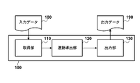
ここで図1Aを参照して、本実施例に係る情報処理装置100について詳しく説明する。本実施例に係る情報処理装置100は、取得部110と、運動導出部120と、出力部130とを備える。
Here, the information processing apparatus 100 according to the present embodiment will be described in detail with reference to FIG. 1A. The information processing apparatus 100 according to the present embodiment includes an acquisition unit 110, an exercise derivation unit 120, and an output unit 130.
取得部110は、患者Xの上顎モデル及び下顎モデルをそれぞれ示す入力データ180を取得する。入力データ180は、三次元データでありうる。三次元データの取得方法としては、様々な方法を用いることができる。例えば、本実施例に係る情報処理装置が撮影手段(不図示)を備えてもよい。この撮影手段が患者の上顎及び下顎を撮影することにより、取得部110は、上顎モデル及び下顎モデルをそれぞれ示す三次元データを取得することができる。
The acquisition unit 110 acquires input data 180 indicating the upper jaw model and the lower jaw model of the patient X, respectively. The input data 180 can be three-dimensional data. Various methods can be used as a three-dimensional data acquisition method. For example, the information processing apparatus according to the present embodiment may include a photographing unit (not shown). When the imaging unit images the upper jaw and lower jaw of the patient, the acquisition unit 110 can acquire three-dimensional data indicating the upper jaw model and the lower jaw model, respectively.
この撮影手段は、直接三次元画像を撮影できてもよい。例えば、3M ESPEのC.O.S(チェアーサイド・オーラル・スキャナー)などを用いることができる。DICO(株)、スリーディ・システム・ジャパン、ニコン、コニカ・ミノルタ、Image Instruments、Exocadなど、他社製品機器も同様なものがある。顔面の3D写真も重要であって、Image Instrumentsのソフトも活用できる。一方でこの撮影手段は、二次元画像を撮影してもよい。この場合、撮影手段によって撮影された二次元画像は、周知の方法によって、三次元データへと変換される。この変換は、本実施例に係る情報処理装置が有する変換手段(不図示)が行ってもよい。またこの変換は、本実施例に係る情報処理装置とは独立の変換装置が行ってもよい。この二次元画像としては例えば、X線写真、セファロ、歯科用CT、歯列パノラマ写真、光学スキャンニング(これは現在14ミクロンの精度を有している装置(3-shapeの機器)などを用いることができる)などを用いることができるが、これらには限定されない。上顎モデル及び下顎モデルをそれぞれ示す三次元データへと変換されうる二次元画像であれば十分である。
This imaging means may be able to directly capture a 3D image. For example, 3M ESPE C.I. O. S (chair side oral scanner) or the like can be used. There are similar products from other companies such as DICO Corporation, 3D System Japan, Nikon, Konica Minolta, Image Instruments, Exocad. The 3D photo of the face is also important, and you can use Image Instruments software. On the other hand, this photographing means may photograph a two-dimensional image. In this case, the two-dimensional image photographed by the photographing means is converted into three-dimensional data by a known method. This conversion may be performed by conversion means (not shown) included in the information processing apparatus according to the present embodiment. Further, this conversion may be performed by a conversion device independent of the information processing apparatus according to the present embodiment. As this two-dimensional image, for example, an X-ray photograph, a cephalo, a dental CT, a dentition panoramic photograph, an optical scanning (this is an apparatus (currently a 3-shape apparatus) having an accuracy of 14 microns). Can be used, but is not limited thereto. Any two-dimensional image that can be converted into three-dimensional data representing the upper jaw model and the lower jaw model is sufficient.
取得部110は、上述の二次元データ又は三次元データを外部から取得してもよい。例えば、ユーザが、上述の二次元データ又は三次元データを取得部110へと入力してもよい。また取得部110は、上述の二次元データ又は三次元データを独立の装置から受信することにより取得してもよい。例えば、遠隔装置から、通信回線を通して、上述の二次元データ又は三次元データを受信してもよい。この遠隔装置とは、画像撮影機器であってもよいし、歯科医院に備えられたコンピュータであってもよい。
The acquisition unit 110 may acquire the above-described two-dimensional data or three-dimensional data from the outside. For example, the user may input the above-described two-dimensional data or three-dimensional data to the acquisition unit 110. The acquisition unit 110 may acquire the above-described two-dimensional data or three-dimensional data by receiving it from an independent device. For example, the above-described two-dimensional data or three-dimensional data may be received from a remote device through a communication line. The remote device may be an image capturing device or a computer provided in a dental clinic.
さらに、取得部110が取得する上顎モデル及び下顎モデルは、パラメータによって表されていてもよい。このパラメータは、患者X個人の上顎と下顎との少なくとも一方の構造を示すパラメータでありうる。例えば、Hobo S, Takayama H: Oral Rehabilitation clinical determination of Occlusion, 1997. Quintessence Publishing Co, Inc. で使用されているパラメータを、このパラメータとして用いることができる。取得部110は、上述の二次元データ又は三次元データから、このようなパラメータを算出してもよい。
Further, the upper jaw model and the lower jaw model acquired by the acquisition unit 110 may be represented by parameters. This parameter may be a parameter indicating the structure of at least one of the upper jaw and the lower jaw of the patient X individual. For example, parameters used in Hobo S, Takayama H: Oral Rehabilitation clinical determination of Occlusion, 1997. Quintessence Publishing Co, Inc. can be used as this parameter. The acquisition unit 110 may calculate such parameters from the above-described two-dimensional data or three-dimensional data.
運動導出部120は、取得部110が取得した上顎モデル及び下顎モデルをそれぞれ示す三次元データを用いて、上顎モデルと下顎モデルとの間の偏心運動を導出する。本実施例において運動導出部120が導出する偏心運動は、基準的な咬頭傾斜角に従う偏心運動であるかもしれない。電子的計測と運動学的解析から、臼歯離開の要因は、顆路・切歯路・咬頭傾斜角の3つから構成されていることが分かっている。咬頭傾斜角は、個人間でのばらつきが少ないことが分かっている。したがって、基準的な咬頭傾斜角に従う偏心運動は、個人間でばらつきの少ない、基準的な(理想的な)偏心運動であるといえる。上顎と下顎とが適正に咬合している場合、こうして導出された偏心運動において上顎と下顎とは正しく接触するものと考えられる。したがってこうして導出された偏心運動は、歯科医師に対する有益な診療情報となりうる。偏心運動とは、顎頭頚部の特に上顎骨体に対する、下顎歯列弓の前方、側方、後方への運動の総称である。ここで偏心運動には、咬頭嵌合位より後方、側方、あるいは前方への運動を含み、特に前方滑走運動及び側方滑走運動を含む。咬頭嵌合位とは、最大接触面積で上下歯牙が嵌合している際の位置を指す。側方運動は、作業側運動と非作業側運動に分類される。これは、1本ずつの上下歯牙の狭義的にも同様な運動としても表現される。顎機能時に使用される、咬頭嵌合位より後方、側方、あるいは前方へ変位した咬合位を偏心咬合位という。解剖学的には、咬頭頂から裂溝部あるいは頬舌側の辺縁隆線に至る咬頭斜面の傾きを咬頭傾斜といい、これと歯の長軸に垂直な平面とがなす角を咬頭傾斜角という。咬頭傾斜角を用いる理由としては、高山の理論式の誕生にまつわる臼歯離開量を再現するために、上梓しているように、顆路・切歯路・咬頭傾斜角の3要素を発見したことがある。このうち咬頭傾斜角は非常にバラツキが少なく、ブレのある顆路やバラツキのある切歯路に比べ約4倍の信頼度がある。つまり、咬頭傾斜角は歯牙の展開角度と考えられる。下顎運動理論式から顆路・前歯・臼歯の形態の再現が可能であって、前歯と臼歯を別個に再現することで臼歯離開量も再現できる。さらに、切歯指導板及び樋状テーブルの機能を再現しうるため、歯牙の角度的形態(咬頭傾斜角及び切歯路角)を再現することができる。咬合学カラーアトラス、及び英語版の著書のインビボ・インビトロの臨床知見において立証されている。
The motion deriving unit 120 derives an eccentric motion between the upper jaw model and the lower jaw model using the three-dimensional data indicating the upper jaw model and the lower jaw model acquired by the acquisition unit 110, respectively. In this embodiment, the eccentric motion derived by the motion deriving unit 120 may be an eccentric motion according to a standard cusp inclination angle. From the electronic measurement and kinematic analysis, it is known that the factor of molar separation is composed of the condyle path, the incisal path, and the cusp inclination angle. It has been found that the cusp tilt angle has little variation among individuals. Therefore, it can be said that the eccentric motion according to the standard cusp inclination angle is a standard (ideal) eccentric motion with little variation among individuals. When the upper jaw and the lower jaw are properly occluded, it is considered that the upper jaw and the lower jaw are in proper contact with each other in the eccentric motion thus derived. Therefore, the eccentric motion thus derived can be useful medical information for the dentist. Eccentric movement is a general term for the forward, lateral, and backward movements of the mandibular dental arch with respect to the maxillary bone, particularly the maxilla. Here, the eccentric movement includes movement backward, laterally or forward from the intercuspal position, and particularly includes forward sliding movement and lateral sliding movement. The cusp fitting position refers to the position when the upper and lower teeth are fitted with the maximum contact area. Side movement is classified into working side movement and non-working side movement. This is expressed as a similar movement of the upper and lower teeth one by one. An occlusal position displaced backward, laterally, or forward from the intercuspal position used during jaw function is called an eccentric occlusal position. Anatomically, the inclination of the cusp slope from the tip of the cusp to the fissure or the ridge of the cheek tongue is called the cusp inclination, and the angle between this and the plane perpendicular to the long axis of the tooth is the cusp inclination angle That's it. The reason for using the cusp inclination angle is to discover the three elements of condylar tract, incisor tract, and cusp inclination angle, as shown above, in order to reproduce the amount of molar distraction associated with the birth of Takayama's theoretical formula. is there. Of these, the inclination angle of the cusp has very little variation and is about four times as reliable as the condylar path with blur and the incisal path with variation. That is, the inclination angle of the cusp is considered to be the expansion angle of the tooth. The shape of the condyle path, anterior teeth, and molars can be reproduced from the theoretical formula of mandibular movement, and the amount of molar separation can be reproduced by reproducing the anterior teeth and molars separately. Furthermore, since the functions of the incisor guidance plate and the bowl-shaped table can be reproduced, the angular form of the teeth (the cusp inclination angle and the incisal path angle) can be reproduced. Proven in occlusal color atlases and in vivo in vitro clinical findings in English books.
偏心運動を導出するための方法として、本実施例においては以下の理論式(1)を用いる。もちろん、他の手法、例えばアキシオグラフによる顎運動の採得、チェックバイト法、ゴツィック・アーチ法など、を用いて偏心運動を導出してもよい。本願において、以下の理論式(1)をITH下顎運動理論式と呼ぶ。ITH下顎運動理論式を用いることにより、3軸6自由度の顎運動を表現することができる。理論式(1)は、請求項に記載の上記説明した内容の新理論式も含めて、バーチャル咬合器ソフトの開発に必須な条件として大事である。以下で図4を用いて説明するように、3軸6自由度の顎運動は、(X,Y,Z)軸方向の並進運動、及び原点周りの回転運動(γ,δ,θ)として表現することができる。
As a method for deriving the eccentric motion, the following theoretical formula (1) is used in this embodiment. Of course, the eccentric motion may be derived by using another method, for example, taking jaw motion by an axiograph, the check bite method, the Gotzic arch method, or the like. In the present application, the following theoretical formula (1) is referred to as an ITH mandibular movement theoretical formula. By using the ITH mandibular movement theory formula, it is possible to express jaw movement with 3 axes and 6 degrees of freedom. Theoretical formula (1) is important as an indispensable condition for the development of virtual articulator software, including the new theoretical formula described above in the claims. As will be described below with reference to FIG. 4, the jaw movement with three axes and six degrees of freedom is expressed as translational movement in the (X, Y, Z) axis direction and rotational movement (γ, δ, θ) around the origin. can do.
本来、下顎は上記にある6つの移動である回転と滑走平行移動が同時に起こり、移動経路を解析するのは難しい。しかし、今解析の目的は、移動経路ではなく移動前後の変位が目的である。また、物体の位置の変位は動きの順序に全く影響を受けないので、6つの移動を独立に考えても問題はない。よって、今回は回転運動→滑走平行移動の順に考える。以上より運動の基本式は以下のようになる。(A,B,Cはそれぞれ移動前のX,Y,Z成分、ΔOx,ΔOy,ΔOzはそれぞれ滑走平行移動のX,Y,Z成分である。)
Originally, the lower jaw has the above six movements of rotation and sliding parallel movement at the same time, and it is difficult to analyze the movement path. However, the purpose of this analysis is not the movement path but the displacement before and after movement. Further, since the displacement of the position of the object is not affected at all by the order of movement, there is no problem even if the six movements are considered independently. Therefore, this time, consider the order of rotational motion → sliding parallel movement. From the above, the basic equation of motion is as follows. (A, B, and C are the X, Y, and Z components before movement, and ΔOx, ΔOy, and ΔOz are the X, Y, and Z components of the sliding translation, respectively.)
[ITH下顎運動理論式(1)]
ΔX=-B×δ-C×Θ+ΔOx
ΔY= C×γ+A×δ+ΔOy
ΔZ= A×Θ-B×γ+ΔOz
[ITH mandibular movement theory (1)]
ΔX = −B × δ−C × Θ + ΔOx
ΔY = C × γ + A × δ + ΔOy
ΔZ = A × Θ−B × γ + ΔOz
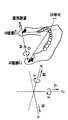
理論式(1)は、下顎の運動を表す理論式である。以下に、式(1)について説明する。下顎運動を解析するためにまず上顎に固定した座標系を前後方向をX軸(前+)、左右方向をY軸(右+)、上下方向をZ軸(下+)と設定する。3次元空間内の下顎の任意の点の変位は3次元の滑走平行移動と3次元の回転の6つの移動で表すことができる。
Theoretical formula (1) is a theoretical formula representing the mandibular movement. Below, Formula (1) is demonstrated. In order to analyze the mandibular movement, first, a coordinate system fixed to the upper jaw is set with the front-rear direction as the X axis (front +), the left-right direction as the Y axis (right +), and the up-down direction as the Z axis (lower +). The displacement of an arbitrary point of the lower jaw in the three-dimensional space can be expressed by six movements of a three-dimensional sliding translation and a three-dimensional rotation.
下顎の運動は前方運動と側方運動の大きく2つの運動に分けられ、所謂、適正な中心位から前方領域の運動と後方領域の運動の計4つに分類される。前方運動では顆頭間軸と正中面との交点を原点に、側方運動においては運動前の作業側の顆頭中心を原点とする。なお、側方運動は右側方運動と左側方運動があるが、これらは正中面で対称な運動をするので、右側方運動について解析する。X-Y平面内での回転角をδ(rad)、Y-Z平面内での回転角をγ(rad)、顆頭間軸を回転軸とした回転の回転角をθ(rad)とする。
The mandibular movement is roughly divided into two movements, the forward movement and the lateral movement, and is classified into four in total, from the so-called proper central position to the movement in the front area and the movement in the rear area. In the anterior movement, the intersection of the intercondylar axis and the median plane is the origin, and in the lateral movement, the condylar center on the working side before the movement is the origin. Side motion includes right side motion and left side motion. Since these motions are symmetrical on the median plane, the right side motion is analyzed. The rotation angle in the XY plane is δ (rad), the rotation angle in the YZ plane is γ (rad), and the rotation angle with the intercondylar axis as the rotation axis is θ (rad). .
このように、式(1)では、上顎に固定した基準座標系が用いられる。この座標系においては、前後方向がX軸、左右方向がY軸、上下方向がZ軸である。それぞれ、前、右、下を正方向とする。すなわち、X-Y面は水平面であり、Y-Z面は前頭面であり、Z-X面は矢状面である。
Thus, in the equation (1), a reference coordinate system fixed to the upper jaw is used. In this coordinate system, the front-rear direction is the X axis, the left-right direction is the Y-axis, and the up-down direction is the Z-axis. The front, right, and bottom are the positive directions, respectively. That is, the XY plane is a horizontal plane, the YZ plane is a frontal plane, and the ZX plane is a sagittal plane.
また、下顎の一点を運動座標系の原点Oとし、運動座標系の座標軸(x,y,z)は基準座標系の座標軸(X,Y,Z)に平行であるものとする。そして、下顎の並進運動及び回転運動を含む運動を行った後の原点Oの三次元変位を、(ΔOx,ΔOy,ΔOz)とする。また、下顎運動後の、運動座標系のy軸がX-Y面内でY軸となす角のラジアン表示(前から見て時計回りの向きを正)をδとする。同様に、y軸がY-Z面内でY軸となす角のラジアン表示(前から見て時計回りの向きを正)をγとする。さらに、回転δ及びγが行われたあとz-x面がy軸の周りに回転する角のラジアン表示(右からみて時計回りの向きを正)をΘとする。以上の定義については図4に示されている。
Also, it is assumed that one point of the lower jaw is the origin O of the motion coordinate system, and the coordinate axes (x, y, z) of the motion coordinate system are parallel to the coordinate axes (X, Y, Z) of the reference coordinate system. Then, the three-dimensional displacement of the origin O after performing the motion including the translational motion and the rotational motion of the lower jaw is defined as (ΔOx, ΔOy, ΔOz). Further, δ is the radian display of the angle that the y-axis of the movement coordinate system makes with the Y-axis in the XY plane after the mandibular movement (the clockwise direction when viewed from the front is positive). Similarly, γ is a radians display of the angle that the y axis makes with the Y axis in the YZ plane (the clockwise direction when viewed from the front is positive). Further, let Θ be the radian display of the angle at which the zx plane rotates around the y-axis after the rotations δ and γ (the clockwise direction as viewed from the right is positive). The above definition is shown in FIG.
この場合に、運動座標系の位置(A,B,C)にある下顎上の任意の一点の基準座標系に対する三次元変位が、理論式(1)を用いて、(ΔX,ΔY,ΔZ)で表される。
In this case, the three-dimensional displacement with respect to the reference coordinate system at an arbitrary point on the lower jaw at the position (A, B, C) of the motion coordinate system is expressed by (ΔX, ΔY, ΔZ) using the theoretical formula (1). It is represented by
この式はA,B,C,δ,γ,Θ,ΔOx,ΔOy,ΔOzの全てについて符号を考えなければならない煩雑さがあるが、前方領域や後方領域、前方運動や側方運動の全てを含めた、滑走平行移動と回転運動の6つの移動の全ての動きについてこの式で解析をする事ができ、以下に挙げる式の基となっている。
Although this expression has the complexity of having to consider signs for all of A, B, C, δ, γ, Θ, ΔOx, ΔOy, and ΔOz, all of the forward region, the backward region, the forward motion, and the lateral motion All of the six movements, including the sliding parallel movement and the rotational movement, can be analyzed using this formula, which is the basis of the following formula.
理論式(1)に基づいて、中心位咬合又は咬頭嵌合位よりも前方(前方運動領域)の顎の運動を表す前方運動理論式(1-1)と、咬頭嵌合位よりも後方(後方運動領域)の顎の運動を表す後方運動理論式(1-2)とが得られる。これら異なるそれぞれの式に従って、前方運動領域及び後方運動領域における顎運動を導出することができる。すなわち、前方運動理論式(1-1)に従って、患者Xの上顎モデル及び下顎モデル、又はこれらを表すパラメータから、前方運動領域における患者Xが実際に行っている顎運動、すなわち中心位咬合又は咬頭嵌合位から下顎歯列弓が前方に移動している様、を導出することができる(第2の計算方法)。同様に、後方運動理論式(1-2)に従って、患者Xの上顎モデル及び下顎モデル、又はこれらを表すパラメータから、後方運動領域における患者Xが実際に行っている顎運動、すなわち中心位咬合又は咬頭嵌合位から下顎歯列弓が後方に移動している様、を導出することができる(第1の計算方法)。
Based on the theoretical formula (1), the forward movement theoretical formula (1-1) representing the movement of the jaw in front of the center position occlusion or the cusp fitting position (forward movement region), and the posterior position of the cusp fitting position ( The backward movement theory formula (1-2) representing the movement of the jaw in the backward movement area) is obtained. According to each of these different equations, jaw movements in the forward movement area and the backward movement area can be derived. That is, according to the forward movement theory formula (1-1), from the upper jaw model and lower jaw model of the patient X or parameters representing them, the jaw movement actually performed by the patient X in the forward movement area, that is, the central occlusion or the cusp It can be derived that the lower dental arch is moving forward from the fitting position (second calculation method). Similarly, according to the backward movement theory formula (1-2), from the upper jaw model and lower jaw model of the patient X or parameters representing them, the jaw movement actually performed by the patient X in the backward movement region, that is, the central occlusion or It can be derived that the lower dental arch is moving backward from the intercuspal position (first calculation method).
まず、前方運動理論式(1-1)(高山の運動理論式)について説明する。計算を簡単にするためにA,B,Cは移動前のX座標、Y座標、Z座標のそれぞれの絶対値、δ,γ,Θは回転角の大きさとして、この6つについてはすべて正の値を代入すればよいように符号を調整した式が以下の(1-1)式である。
[前方運動理論式(1-1)]
ΔX= B×δ-C×Θ+ΔOx
ΔY= C×γ+A×δ+ΔOy
ΔZ= A×Θ+B×γ+ΔOz
First, the forward motion theory formula (1-1) (Takayama's motion theory formula) will be described. To simplify the calculation, A, B, and C are the absolute values of the X coordinate, Y coordinate, and Z coordinate before the movement, and δ, γ, and Θ are the magnitudes of the rotation angles. The following equation (1-1) is obtained by adjusting the sign so as to substitute the value of.
[Theoretical formula for forward motion (1-1)]
ΔX = B × δ−C × Θ + ΔOx
ΔY = C × γ + A × δ + ΔOy
ΔZ = A × Θ + B × γ + ΔOz
前方運動理論式(1-1)からは、前方運動を表す式(1-1-1)と、側方運動(右側方運動及び左側方運動)を表す式(1-1-2)とを導くことができる。以下の式において、
Ωcp:前方運動において顆頭間軸中点の運動軌跡が矢状面内で水平基準面となす傾斜角(左右の矢状前方顆路傾斜角の平均)
Λcp:平均前方顆路長(√((ΔXcp,ave)2+(ΔZzp,ave)2):三平方)
Δcl:側方顆路長(√(ΔXcl2+ΔYcl2+ΔZcl2))
ΔXcp,ave:左右顆頭中心の前方変位の平均(顆頭間軸中点の前方変位)
ΔZcp,ave:左右顆頭中心の下方変位の平均(顆頭間軸中点の下方変位)
ΔXwl:作業側顆頭中心の前方変位
ΔYwl:作業側顆頭中心の側方変位(ただし右側方運動のときは右を正、左側方運動のときは左を正)
ΔZwl:作業側顆頭中心の下方変位
ΔXil:切歯点の前方変位
ΔYil:切歯点の側方変位(ただし右側方運動のときは右を正、左側方運動のときは左を正)
ΔZil:切歯点の下方変位
Ωcp=tan-1(ΔZcp,ave/ΔXcp,ave):前方運動において顆頭間軸中点の運動軌跡が矢状面内で水平基準面となす傾斜角(左右の矢状前方顆路傾斜角の平均)
Ωcl=tan-1(ΔZcl/ΔXcl):側方運動において非作業側の顆路が矢状面内で水平基準面となす傾斜角(矢状側方顆路傾斜角)
Be=tan-1(ΔYcl/ΔXcl):側方運動において非作業側の顆路が水平面内で矢状面となす傾斜角(ベネット角、または水平側方顆路角)
Ωip=tan-1(ΔZip/ΔXip):前方運動において切歯路が矢状面内で水平基準面となす傾斜角(矢状前方切歯路傾斜角)
Ωil=tan-1(ΔZil/ΔXil):側方運動において切歯路が矢状面内で水平基準面となす傾斜角(矢状側方切歯路傾斜角)
Φil=tan-1(ΔZil/ΔYil):側方運動において切歯路が前頭面内で水平基準面となす傾斜角(前頭側方切歯路傾斜角)
Ψil=tan-1(ΔYil/ΔXil):側方運動において切歯路が水平面内で矢状面となす角(水平側方切歯路角、またはゴツィック・アーチ角)
Θhp:前方運動における顆頭間軸(y軸)の回りの回転角のラジアン表示:前方運動におけるΘ(前方蝶番回転角)
Θhl:側方運動における顆頭間軸(y軸)の回りの回転角のラジアン表示:側方運動におけるΘ(側方蝶番回転角)
δl:側方運動における作業側顆頭中心を通り顆頭間軸と非作業側顆路とを含む面に垂直な軸の回りの回転角の水平面投影のラジアン表示:側方運動におけるδ(水平側方回転角)
γl:側方運動における作業側顆頭中心を通り顆頭間軸と非作業側顆路とを含む面に垂直な軸の回りの回転角の前頭面投影のラジアン表示:側方運動におけるγ(前頭側方回転角)
Lc:左右の顆頭中心C,C’間の距離:顆頭間軸C-C’の長さ(顆頭間距離)
(Ai,Bi,Ci):切歯点の運動座標系における3次元座標
を表す。また、前方運動式においては顆頭間軸と正中面との交点Mを運動座標系の原点とする。さらに、側方運動式においては作業側の顆頭中心C,C’を原点とする。これらの点については図4に示されている。
From the forward motion theory formula (1-1), the formula (1-1-1) representing forward motion and the formula (1-1-2) representing side motion (right side motion and left side motion) are obtained. Can lead. In the following formula:
Ωcp: Inclination angle between the trajectory of the intercondylar axis midpoint in the anterior motion and the horizontal reference plane in the sagittal plane (average of right and left sagittal anterior condylar tilt angles)
Λcp: mean anterior condylar path length (√ ((ΔXcp, ave) 2 + (ΔZzp, ave) 2 ): three squares)
Δcl: lateral condyle path length (√ (ΔXcl 2 + ΔYcl 2 + ΔZcl 2 ))
ΔXcp, ave: average of anterior displacement at the center of the left and right condyles (anterior displacement of midpoint between condylar axes)
ΔZcp, ave: Average of the downward displacement of the center of the left and right condyles (downward displacement of the midpoint of the intercondylar axis)
ΔXwl: Anterior displacement at the center of the condyle on the working side ΔYwl: Lateral displacement at the center of the condyle on the working side (However, the right is positive for rightward movement and the left is positive for leftward movement)
ΔZwl: Downward displacement of the working side condyle center ΔXil: Anterior displacement of the incisor point ΔYil: Lateral displacement of the incisor point (however, the right is positive for rightward movement and the left is positive for leftward movement)
ΔZil: Downward displacement of the incisor point Ωcp = tan -1 (ΔZcp, ave / ΔXcp, ave): Inclination angle (left and right) of the motion trajectory of the midpoint of the intercondylar axis with the horizontal reference plane in the anterior motion Mean sagittal anterior condylar inclination angle)
Ωcl = tan −1 (ΔZcl / ΔXcl): Inclination angle between the non-working condyle path and the horizontal reference plane in the sagittal plane during lateral movement (sagittal lateral condylar path inclination angle)
Be = tan −1 (ΔYcl / ΔXcl): Inclination angle (Bennet angle or horizontal lateral condylar tract angle) that the non-working condylar tract forms a sagittal plane in the horizontal plane in lateral movement
Ωip = tan -1 (ΔZip / ΔXip): Inclination angle that the incisal path makes with the horizontal reference plane in the sagittal plane during forward movement (sagittal forward incision path inclination angle)
Ωil = tan −1 (ΔZil / ΔXil): Inclination angle that the incisal path makes with the horizontal reference plane in the sagittal plane during lateral movement (sagittal side incision angle)
Φil = tan -1 (ΔZil / ΔYil): Inclination angle between the incisal tract and the horizontal reference plane in the frontal plane in lateral movement (frontal side incision tract inclination angle)
Ψil = tan −1 (ΔYil / ΔXil): Angle that the incisal tract forms with the sagittal plane in the horizontal plane in the lateral movement (horizontal lateral incision tract angle or Gotick arch angle)
Θhp: Radian display of rotation angle around the intercondylar axis (y-axis) in anterior movement: Θ (anterior hinge rotation angle) in anterior movement
Θhl: Radian display of rotation angle around intercondylar axis (y-axis) in lateral movement: Θ (lateral hinge rotation angle) in lateral movement
δl: Radian display of horizontal projection of rotation angle about the axis perpendicular to the plane including the intercondylar axis and the non-working condyle path through the center of the condyle in the lateral movement: δ in the lateral movement (horizontal Side rotation angle)
γl: Radian representation of frontal projection of rotation angle around an axis perpendicular to the plane including the intercondylar axis and the non-working condyle path through the center of the working side condyle in lateral movement: γ ( Frontal side rotation angle)
Lc: distance between left and right condyle centers C and C ′: length of intercondylar axis CC ′ (intercondylar distance)
(Ai, Bi, Ci): Represents the three-dimensional coordinates in the motion coordinate system of the incisor point. In the anterior motion equation, the intersection M between the intercondylar axis and the median plane is the origin of the motion coordinate system. Further, in the lateral motion type, the condylar center C, C ′ on the working side is set as the origin. These points are illustrated in FIG.
[前方運動における前方運動式(1-1-1)]
前方領域(前方運動理論式)での前方運動は顆頭間軸を回転軸としてその周りに回転する蝶番回転運動とX軸,Z軸方向にプラスの平行移動の運動である。前方運動では、左右の変位はないとみなすためΔY=0とおいて解析を進める。よって基本式においてδ=0,γ=0,δOy=0と置くことと同値である。また、Θは口が開く方向を+と設定すると、以下のようになる。
ΔX=-C×Θhp+ΔOx
ΔY=0
ΔZ= A×Θhp+ΔOz
[Forward motion formula in forward motion (1-1-1)]
The forward motion in the anterior region (the forward motion theory formula) is a hinge rotational motion that rotates about the intercondylar axis as a rotational axis and a positive parallel motion in the X-axis and Z-axis directions. In the forward motion, since it is considered that there is no left / right displacement, the analysis is advanced with ΔY = 0. Therefore, it is equivalent to placing δ = 0, γ = 0, and δOy = 0 in the basic formula. Θ is as follows when the direction of opening the mouth is set to +.
ΔX = −C × Θhp + ΔOx
ΔY = 0
ΔZ = A × Θhp + ΔOz
滑走平行移動のΔOx,ΔOzは顆頭の平行移動のX,Y成分であるから、ΔOx=cosΩcp×Λcp,ΔOz=sinΩcp×Λcpとなる。(Λcp:顆路長)よって、前方運動の式は以下のようになる。
ΔX= cosΩcp×Λcp-C×Θhp
ΔZ= sinΩcp×Λcp+A×Θhp
Since ΔOx and ΔOz of the sliding translation are the X and Y components of the translation of the condyle, ΔOx = cosΩcp × Λcp and ΔOz = sinΩcp × Λcp. (Λcp: condyle path length) Therefore, the equation of anterior motion is as follows.
ΔX = cosΩcp × Λcp−C × Θhp
ΔZ = sinΩcp × Λcp + A × Θhp
また、
tanΩip=ΔZip/ΔXip
よりΘhpを求めると、
Θhp=((tanΩip-tanΩcp)×cosΩcp×Λcp)/(Ci×tanΩip+Ai)
と求まる。
Also,
tanΩip = ΔZip / ΔXip
From Θhp,
Θhp = ((tanΩip−tanΩcp) × cosΩcp × Λcp) / (Ci × tanΩip + Ai)
It is obtained.
[前方運動における側方運動式(1-1-2)]
側方運動は作業側の顆頭中心を中心としたX-Y平面の回転運動、Y-Z平面の回転運動と蝶番回転運動の3次元の回転運動と、顆頭の3次元の滑走平行移動(ΔXwl,ΔYwl,ΔZwl)の運動であり、下記のように表せる。
ΔX= B×δl -C×Θhl +ΔXwl
ΔY= C×γl +A×δl +ΔYwl
ΔZ= A×Θhl +B×γl +ΔZwl
[Side motion formula for forward motion (1-1-2)]
Lateral movements are rotational movements on the XY plane around the condylar center on the working side, three-dimensional rotational movements of the YZ plane and hinges, and three-dimensional sliding translation of the condyles. It is a motion of (ΔXwl, ΔYwl, ΔZwl) and can be expressed as follows.
ΔX = B × δl −C × Θhl + ΔXwl
ΔY = C × γl + A × δl + ΔYwl
ΔZ = A × Θhl + B × γl + ΔZwl
この式に作業側、非作業側の顆頭中心の座標を代入してδl,γlについて解くと、
δl=(ΔXcl-ΔXwl)/Lc=(Λcl×cosΩcl)/Lc
γl=(ΔZcl-ΔZwl)/Lc
となり、
tanΩcl=ΔZcl/ΔXcl
より、
γl=tanΩcl×δl+(ΔXwl×tanΩcl-ΔZwl)/Lc
また、
tanΦil=ΔZil/ΔYil
より、
Θhl=(δl/Ai)×((Ci×tanΩcl+Ai+Lc×tanBe)×tanΦil-(Lc/2)×tanΩcl)
が求まり、他に
ΔYwl=(Lc×δl+ΔXwl)×tanBe
が得られる。(ΔXwl,ΔZwlは測定により求める。測定できない場合は0として計算する。)
Substituting the coordinates of the condylar center on the working side and the non-working side into this equation and solving for δl and γl,
δl = (ΔXcl−ΔXwl) / Lc = (Λcl × cosΩcl) / Lc
γl = (ΔZcl−ΔZwl) / Lc
And
tanΩcl = ΔZcl / ΔXcl
Than,
γl = tanΩcl × δl + (ΔXwl × tanΩcl−ΔZwl) / Lc
Also,
tanΦil = ΔZil / ΔYil
Than,
Θhl = (δl / Ai) × ((Ci × tanΩcl + Ai + Lc × tanBe) × tanΦil− (Lc / 2) × tanΩcl)
And ΔYwl = (Lc × δl + ΔXwl) × tanBe
Is obtained. (ΔXwl and ΔZwl are obtained by measurement. If measurement is not possible, 0 is calculated.)
以上の式は1次近似を用いた近似式であるため、10-1mmまでは信頼できる値として求められる。さらに精度を上げるための2次微小の項は以下のようであり、これを1次近似の式に加えることで10-3mmまで求められるようになる。
ΔΔX=-A×((δl2+Θh2)/2)-C×δlγl/2
ΔΔY= B×((δl2+γl2)/2)+A×γlΘh-C×δlΘh
ΔΔZ=-C×((γl2+Θh2)/2)-A×δlγl/2
Since the above equation is an approximation equation using a first-order approximation, a value up to 10 −1 mm is obtained as a reliable value. The second-order minute term for further improving the accuracy is as follows. By adding this to the first-order approximation formula, it becomes possible to obtain up to 10 −3 mm.
ΔΔX = −A × ((δl 2 + Θh 2 ) / 2) −C × δlγl / 2
ΔΔY = B × ((δl 2 + γl 2 ) / 2) + A × γlΘh−C × δlΘh
ΔΔZ = −C × ((γl 2 + Θh 2 ) / 2) −A × δlγl / 2
次に、後方運動理論式(1-2)について説明する。高山が発表した下顎運動の理論式は適正な中心位から前方の領域に移動する運動のみについて書かれているが、ITH下顎運動理論式は適正な中心位から後方の領域も含めた運動に対して解析が行うことができ、下顎が後方に移動する際に必要となる臼歯の傾斜角度を求められるようになった。以下に詳細を記す。
Next, the backward motion theory formula (1-2) will be described. The theoretical formula for mandibular movement published by Takayama is written only for the movement from the proper center position to the front area, but the ITH mandibular movement theory formula is for the movement including the rear area from the proper center position. Analysis, and the inclination angle of the molars required for the lower jaw to move backward can be obtained. Details are described below.
[後方運動理論式(1-2)]
ΔX=-B×δ-C×Θ+ΔOx
ΔY= C×γ-A×δ+ΔOy
ΔZ= A×Θ+B×γ+ΔOz
後方運動理論式(1-2)からも、前方運動を表す式(1-2-1)と、側方運動(右側方運動及び左側方運動)を表す式(1-2-2)とを導くことができる。
[Backward movement theory (1-2)]
ΔX = −B × δ−C × Θ + ΔOx
ΔY = C × γ−A × δ + ΔOy
ΔZ = A × Θ + B × γ + ΔOz
From the backward motion theory formula (1-2), the formula (1-2-1) representing the forward motion and the formula (1-2-2) representing the lateral motion (right side motion and left side motion) are also obtained. Can lead.
[後方運動における前方運動式(1-2-1)]
後方領域の前方運動は前方運動理論式の運動と比べると、蝶番回転運動は同じで口が開く方向が+と設定してあるが、滑走平行移動についてはX軸は-、Z軸は+の方向に動くので以下のようになる。
ΔX=-cosΩcp×Λcp-C×Θhp
ΔZ= sinΩcp×Λcp+A×Θhp
Θhp=((tanΩip-tanΩcp)×cosΩcp×Λcp)/(Ai-Ci×tanΩip)
[Forward motion formula in backward motion (1-2-1)]
The forward motion in the rear region is the same as the hinge rotational motion and the mouth opening direction is set to + compared to the motion of the forward motion theory formula, but for sliding translation, the X axis is-and the Z axis is + Since it moves in the direction, it becomes as follows.
ΔX = −cosΩcp × Λcp−C × Θhp
ΔZ = sinΩcp × Λcp + A × Θhp
Θhp = ((tanΩip−tanΩcp) × cosΩcp × Λcp) / (Ai−Ci × tanΩip)
[後方運動における側方運動式(1-2-2)]
後方運動は前方領域の運動と比べると、X-Y平面内での回転δが逆方向に回転する。そのため、Y軸に平行な滑走平行移動ΔYwlも前方運動理論式のそれとは逆の方向に移動すると考える。他の滑走平行移動の2つと回転の2つの動きは前方運動理論式と同じであるから前方運動理論式の式においてδl→-δl、ΔYwl→-ΔYwlに変換すればよい。よって以下のようになる。(前方領域と同じようにδl、γl、2次微小項も求めた。)
[Side motion formula in backward motion (1-2-2)]
Compared with the movement in the front area, the backward movement rotates the rotation δ in the XY plane in the opposite direction. Therefore, it is considered that the sliding translation ΔYwl parallel to the Y axis also moves in the direction opposite to that of the forward motion theoretical formula. Since the two other sliding parallel movements and the two movements of rotation are the same as the forward motion theoretical formula, the forward motion theoretical formula may be converted into δl → −δl and ΔYwl → −ΔYwl. Therefore, it becomes as follows. (Δl, γl, and secondary minute terms were also obtained in the same manner as the front region.)
ΔX=-B×δl -C×Θhl+ΔXwl
ΔY= C×γl -A×δl +ΔYwl
ΔZ= A×Θhl+B×γl +ΔZwl
δl=(ΔXcl-ΔXwl)/Lc=(Λcl×cosΩcl)/Lc
γl=tanΩcl×δl-(ΔXwl×tanΩcl+ΔZwl)/Lc
Θhl=(δl/Ai)×((Ci×tanΩcl-Ai-Lc×tanBe)×tanΦil-(Lc/2)×tanΩcl)
ΔYwl=-(Lc×δl+ΔXwl)×tanBe
ΔΔX=-A×((δl2+Θh2)/2)+C×δlγl/2
ΔΔY= B×((δl2+γl2)/2)+A×γlΘh+C×δlΘh
ΔΔZ=-C×((γl2+Θh2)/2)+A×δlγl/2
ΔX = −B × δl −C × Θhl + ΔXwl
ΔY = C × γl -A × δl + ΔYwl
ΔZ = A × Θhl + B × γl + ΔZwl
δl = (ΔXcl−ΔXwl) / Lc = (Λcl × cosΩcl) / Lc
γl = tanΩcl × δl− (ΔXwl × tanΩcl + ΔZwl) / Lc
Θhl = (δl / Ai) × ((Ci × tanΩcl−Ai−Lc × tanBe) × tanΦil− (Lc / 2) × tanΩcl)
ΔYwl = − (Lc × δl + ΔXwl) × tanBe
ΔΔX = −A × ((δl 2 + Θh 2 ) / 2) + C × δlγl / 2
ΔΔY = B × ((δl 2 + γl 2 ) / 2) + A × γlΘh + C × δlΘh
ΔΔZ = −C × ((γl 2 + Θh 2 ) / 2) + A × δlγl / 2
後方運動理論式より算出した第1臼歯の変位・傾斜度は以下のようになる。
ΔX=-Bδ-CΘ
ΔZ=Cγ-Aδ+ΔYwl
ΔZ=Bγ+AΘ
Θhp=-9.244262507×10⁻³
ΔXmp=-1.558592329
ΔZmp=1.928362829
Ωmp=51.05324
Θhl=-0.0221825621
ΔXmw=0.4052117727
ΔYmw=-0.3822412627
ΔZmw=-0.3127691477
ΔXmnw=-0.5589696418
ΔYmnw=-0.3822412627
ΔZmnw=0.836297517
Φmw=29.69135211
Φmnw=51.00212093
The displacement / inclination degree of the first molar calculated from the backward motion theory is as follows.
ΔX = −Bδ−CΘ
ΔZ = Cγ−Aδ + ΔYwl
ΔZ = Bγ + AΘ
Θhp = −9.244262507 × 10 -3
ΔXmp = -1.558592329
ΔZmp = 1.928362829
Ωmp = 51.05324
Θhl = −0.0221825621
ΔXmw = 0.4052117727
ΔYmw = -0.3822412627
ΔZmw = -0.3127691477
ΔXmnw = −0.5589696418
ΔYmnw = −0.3822412627
ΔZmnw = 0.836297517
Φmw = 29.69135211
Φmnw = 51.00212093
[ベネット角算出について]
この算出法は以下のように、まずアキシス平面上で非作業側の顆頭の変位を算出し、それを他平面から見た座標に変換し、高山の理論式を用いてBe角を算出する。図5及び図6は、この算出方法を示す。まず基準となるアキシス平面で高山の理論式から非作業側の顆頭の座標を求める。
[About Bennett angle calculation]
In this calculation method, first, the displacement of the condyle on the non-working side is calculated on the Axis plane, converted into coordinates viewed from other planes, and the Be angle is calculated using Takayama's theoretical formula. . 5 and 6 show this calculation method. First, the coordinates of the condyle on the non-working side are obtained from the theoretical formula of Takayama on the reference axis plane.
ΔXwl=Lc×δl
ΔYwl=ΔXwl×tanBe=Lc×δl×tanBe
ΔZwl=Lc×γ
より、
ΔXwl=2.29
ΔYwl=0.61
ΔZwl=1.92
が得られる(アキシス平面でのBe角は15°)。座標と図6からX軸とOAのなす角が約40°と求められ、各平面でのx’、Be角を求める式が以下のようになった。
x’=OAcos(40+α)
Be=tan-1(ΔYwl/x’)
ΔXwl = Lc × δl
ΔYwl = ΔXwl × tanBe = Lc × δl × tanBe
ΔZwl = Lc × γ
Than,
ΔXwl = 2.29
ΔYwl = 0.61
ΔZwl = 1.92
(Be angle in the Axis plane is 15 °). From the coordinates and FIG. 6, the angle formed by the X axis and OA was found to be about 40 °, and the equations for obtaining the x ′ and Be angles in each plane were as follows.
x ′ = OAcos (40 + α)
Be = tan −1 (ΔYwl / x ′)
これより各平面の値は以下のようになった。
As a result, the values for each plane were as follows.
以上示したように、運動導出部120はベネット運動の再現理論式に従って、ベネット運動を含む偏心運動を導出することができる。
As described above, the motion deriving unit 120 can derive the eccentric motion including the Bennett motion according to the Bennett motion reproduction theoretical formula.
[各基準咬合平面に対する顆路と樋状の傾斜に対する角度の違いについて]
咬合器には様々な基準平面を用いたものがあり、また、咬合器において樋状傾斜角度と顆路傾斜角度の差をマコーリス(McHorris)は、5°という値が臨床的に良いと報告している。これについて仮想の咬合器を想定して顆頭と樋状か移動した際の変位量を以下のようにして調べる。
[Difference in angle for condylar path and saddle-shaped inclination with respect to each reference occlusal plane]
There are various articulators using various reference planes, and McHorris reports that the value of 5 ° is clinically good for the difference between the angle of inclination and condylar inclination in the articulator. ing. Assuming a virtual articulator, the amount of displacement when moving from the condylar head to the saddle shape is examined as follows.
この側翼角を求めるには、アキシス平面での側翼角の値から、アキシス平面での顆頭を原点とした樋状の位置を算出し、その値を各平面の座標に変換し、側翼角を高山の理論式に用いて算出した。高山の理論式から演算された臼歯部の側翼角と、臼歯部の咬頭路傾斜角は実際の条件1とは異なっている。これが、後方運動の条件となる。(条件3・4)
In order to obtain this side wing angle, from the side wing angle value on the Axis plane, calculate the saddle-shaped position with the condyle on the Axis plane as the origin, convert that value to the coordinates of each plane, and calculate the side wing angle. Calculated using Takayama's theoretical formula. The side wing angle of the molar part calculated from Takayama's theoretical formula and the cusp tract inclination angle of the molar part are different from the actual condition 1. This is a condition for backward movement. (Conditions 3 and 4)
以上に示したITH下顎運動理論式は水平基準面をアキシス平面としていた。これを他平面に応用できるようにする。水平基準面が変わると、矢状面での全ての角度とX座標とZ座標に影響が生じる。矢状面での各角度においてはアキシス平面となす角αだけ引けばよい。X座標とZ座標についての変換法を以下に記す。
In the above ITH mandibular movement theory, the horizontal reference plane is the Axis plane. This can be applied to other planes. If the horizontal reference plane is changed, all angles in the sagittal plane and the X and Z coordinates are affected. For each angle in the sagittal plane, it is sufficient to subtract only the angle α formed with the axis plane. A conversion method for the X coordinate and the Z coordinate is described below.
図11は、アキシス平面と他平面の交わりを示す。図11のように顆頭(C)をアキシス平面と他平面の原点、なす角をαと設定する。アキシス平面上での臼歯(M)、切歯(I)、樋状(G)のX,Z座標はそれぞれ(40,40)、(80,40)、(120,60)であるのでアキシス平面と直線CMとのなす角は45°、直線CIGとのなす角は26.5°と求められた。これより他平面上でのX,Z座標は以下のように求められる。
X’M=40√2×cos(45+α)
Z’M=40√2×sin(45+α)
X’I=40√5×cos(26.5+α)
Z’I=40√5×cos(26.5+α)
X’G=60√5×cos(26.5+α)
X’G=60√5×sin(26.5+α)
FIG. 11 shows the intersection of the Axis plane and the other plane. As shown in FIG. 11, the condyle (C) is set to the origin of the Axis plane and the other plane, and the angle formed by α is set to α. Since the X and Z coordinates of the molar (M), incisor (I), and saddle (G) on the axis plane are (40, 40), (80, 40), and (120, 60), respectively, the axis plane The angle between the straight line CM and the straight line CM was found to be 45 °, and the angle made with the straight line CIG was found to be 26.5 °. From this, the X and Z coordinates on the other plane are obtained as follows.
X ′ M = 40√2 × cos (45 + α)
Z ′ M = 40√2 × sin (45 + α)
X ′ I = 40√5 × cos (26.5 + α)
Z ′ I = 40√5 × cos (26.5 + α)
X ′ G = 60√5 × cos (26.5 + α)
X ′ G = 60√5 × sin (26.5 + α)
これより他平面の座標は以下のようになった。
The coordinates of other planes are as follows.
今回はまず移動前後のアキシス平面での座標から他平面の座標にそれぞれ変換して顆路と樋状の変位を調べる。図7は、矢状面から見た樋状、顆頭の変位を示す。
[This time, first, the coordinates on the Axis plane before and after the movement are converted to the coordinates on the other plane, respectively, and the condylar path and saddle-shaped displacement are examined. FIG. 7 shows the saddle-like and condylar displacements as seen from the sagittal plane.
図7のように下顎の切歯を原点、アキシス平面と他平面との交線が切歯点上にくるように設定した。C1は顆頭の移動前の位置、G1は樋状の移動前の位置であり、G1からX軸方向に-7.1mm、Z軸方向に-7.1mmだけ移動した点をG2とすると、顆頭はC1からX軸方向に-7.8mm、Z軸方向に-6.2mmだけ移動した(この点をC2とする)。ITH下顎運動理論式の他平面への応用より他平面での座標(X’c1 , Z’c1)、(X’g1 , Z’g1)は求まっている。また、X’c2、Z’c2、X’g2、Z’g2は以下のように求まる。
X’C2=X’C1-10×cos(40-α)
Z’C2=Z’C1-10×sin(40-α)
X’G2=X’G1-10×cos(45-α)
Z’G2=Z’G1-10×sin(45-α)
これより求まった数値は以下のような結果である。
As shown in FIG. 7, the incisor of the lower jaw was set to the origin, and the line of intersection between the axis plane and the other plane was set on the incisor point. C1 is a position before movement of the condyle, G1 is a position before movement of the saddle shape, and G2 is a point moved from G1 by −7.1 mm in the X-axis direction and by −7.1 mm in the Z-axis direction. The condyle moved from C1 by -7.8 mm in the X-axis direction and by -6.2 mm in the Z-axis direction (this point is referred to as C2). Coordinates (X'c1, Z'c1) and (X'g1, Z'g1) in other planes are obtained from the application of the ITH mandibular movement theory formula to other planes. X′c2, Z′c2, X′g2, and Z′g2 are obtained as follows.
X ′ C2 = X ′ C1 −10 × cos (40−α)
Z ′ C2 = Z ′ C1 −10 × sin (40−α)
X ′ G2 = X ′ G1 −10 × cos (45−α)
Z ′ G2 = Z ′ G1 −10 × sin (45−α)
The numerical values obtained from this are as follows.
これらからX’2-X’1、Z’2-Z’1の計算をすることで各基準平面での変位が求まり、以下のようになった。
From these, by calculating X ′ 2 -X ′ 1 and Z ′ 2 -Z ′ 1 , the displacement in each reference plane was obtained, and the results were as follows.
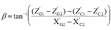
これから下図の各平面のβについて求める。図12は、矢状面から見た顆頭、樋状の変位を示す。図12において、G’1はG2からZ軸に平行に、C2からX軸に平行に引いた線の交点である。G’2はG1からG2のZ成分と同じだけG’1から移動した点である。これよりβは以下のようにして求められる。
From this, β of each plane in the following figure is obtained. FIG. 12 shows the condylar and saddle-like displacements as seen from the sagittal plane. In FIG. 12, G′1 is an intersection of lines drawn from G2 parallel to the Z axis and from C2 parallel to the X axis. G′2 is a point moved from G′1 by the same amount as the Z component from G1 to G2. From this, β is obtained as follows.
他平面についても同様に以下のようになる。
The same applies to the other planes.
これより各平面で求まったβは以下のようになった。
From this, β found in each plane is as follows.
[ITH下顎運動理論式を他平面に応用するにあたって]
ITH下顎運動理論式を他平面に用いるにあたって、矢状面の角度、ベネット角など、あらゆる角度について一度考慮して計算しなければならない。これを考慮しなかった場合と考慮した場合の計算結果を以下に記す。なお、顆頭、切歯、樋状の各平面でのX,Z座標は、上に示した通りである。(Y座標は基準平面が変わっても座標の数値は不変である。)また、矢状面角度は比較のためにアキシス平面に変換し直した。
[In applying ITH mandibular movement theory to other planes]
When the ITH mandibular movement theory formula is used for other planes, it must be calculated once considering all angles such as sagittal angle and Bennett angle. The calculation results when this is not considered and when it is considered are described below. The X and Z coordinates in the condylar, incisor, and saddle-shaped planes are as shown above. (The coordinate value of the Y coordinate is unchanged even if the reference plane changes.) The sagittal plane angle is converted back to the axis plane for comparison.
平面が変わるとX,Z座標が変化し、Y座標は変化しないので各平面においての矢状面、前頭面、水平面角度、ベネット角など全ての値が変わる。各平面でITH下顎運動理論式を計算するにあたって、矢状面角度(Ωcp、Ωip、Ωgp、Ωcl)、前頭面角度(Φil)、ベネット角(Be)について各平面に合った数値で計算しなければならない。これまでの値はアキシス平面での値であった。他平面にもITH下顎運動理論式を活用するには以下の計算をし、それぞれの値を使わなければならない。
When the plane changes, the X and Z coordinates change, and the Y coordinate does not change, so all values such as the sagittal plane, frontal plane, horizontal plane angle, and Bennett angle in each plane change. When calculating the ITH mandibular movement theory formula on each plane, the sagittal plane angle (Ωcp, Ωip, Ωgp, Ωcl), frontal plane angle (Φil), and Bennett angle (Be) must be calculated with values appropriate for each plane. I must. The values so far were values on the axis plane. In order to utilize the ITH mandibular movement theory for other planes, the following calculations must be made and the respective values must be used.
矢状面角度について、他平面での矢状面角度(Ω’)は、アキシス平面の矢状面角度(Ω)にアキシス平面とその平面がなす角αを足せばよい。前頭面角度について、前頭面側方切歯路傾斜度Φilを他平面に合った値に変換するには、まずアキシス平面での側方運動をした後の切歯の座標を求め、その値を他平面の座標に変換しΔZil、ΔYilを求め、その値から各平面でのΦilを求める。ベネット角については別に述べる。また、条件1、条件2の値は以下の通りである。
Regarding the sagittal plane angle, the sagittal plane angle (Ω ′) on the other plane may be obtained by adding the angle α formed by the axis plane and the plane to the sagittal plane angle (Ω) of the axis plane. To convert the frontal surface side incisor slope Φil to a value suitable for other planes, first determine the coordinates of the incisor after lateral movement on the Axis plane. Convert to the coordinates of other planes to obtain ΔZil and ΔYil, and obtain Φil in each plane from these values. The Bennett angle will be described separately. The values of Condition 1 and Condition 2 are as follows.
[アングル1級叢生の抜歯]
アングル1級叢生の抜歯、非抜歯症例からの論文からも述べられているように、仮にフランクフルト平面に対してのU1―L1の角度47°は、実際どのように関係しているかを以下に列挙していく。
[Tooth extraction for Angle Class 1 crowds]
As described in the papers on extraction and non-extraction cases of Angle Class 1 crowding, the following is a list of how the angle 47 ° of U1-L1 with respect to the Frankfurt plane is actually related: I will do it.
ツインホビー咬合器のインサイザルポール・樋状テーブルの位置関係は、下顎切歯から40ミリ前方、垂直に20ミリ下方に再現されていて、顆路中心部から、垂線をおろした前方距離が120ミリである。高山の下顎運動理論式では、顔面間距離を80ミリに設定しているから、40ミリの中間を咬合器に再現する必要がある。実際のツインホビー咬合器の上弓と下弓の高さが、80ミリとすると前歯部・臼歯部を2分割にする手技のために模型を分割にするツインステージ法は、ピンデックスによる上下歯牙分割の高さが、足りない事から保母は、咬合器の上弓フレームを20ミリ上方にスライドさせている。運動理論式の計算には、問題が生じていない。つまり、顆路中心点の位置を切歯路から80ミリに規格した咬合器として製作されている。次に、前方基準点43ミリは、上顎右側中切歯の切端を再現しているので、2.15°下方に上顎咬合平面が再現される。但し、咬合平面は一般的に下顎歯列弓を基準としているので、オーバーバイト、オーバージェット平均3ミリの角度差も考慮する必要がある。上顎中切歯が下顎中切歯より3ミリ(理論式の顆路移動距離3ミリにも相当している。)前方は、83ミリのさいにおける角度が、2.07°である。前での本来の咬合平面として再現される下顎中切歯では、2.15°であるから、ほぼ約2.1°=(2°)の違いがある。つまり、切歯路部における角度は仮想咬合平面を7.37-2.07(2.15)=5.3°(5.22°)に算術された値になる。所謂、この値が、仮想咬合平面とすれば、各水平基準平面と言われている数値と約2°の値が後述する結果に対し、重要なポイントになっていく。
The positional relationship between the twin hobby articulator's incisal pole and saddle-shaped table is reproduced 40mm forward and 20mm downward vertically from the lower incisor, and the forward distance from the center of the condylar path is 120 It is a millimeter. In Takayama's theory of mandibular movement, the distance between the faces is set to 80 mm, so it is necessary to reproduce the middle of 40 mm in the articulator. If the height of the upper and lower arches of an actual twin hobby articulator is 80 mm, the twin stage method that divides the model for the procedure of dividing the anterior and posterior teeth into two parts is the upper and lower teeth by pindex Since the height of the division is insufficient, the nurse has slid the upper bow frame of the articulator 20 mm upward. There is no problem in the calculation of the theory of motion. That is, it is manufactured as an articulator that standardizes the position of the condyle center point to 80 mm from the incisal path. Next, since the front reference point 43 mm reproduces the incisal edge of the maxillary right middle incisor, the maxillary occlusal plane is reproduced below 2.15 °. However, since the occlusal plane is generally based on the lower dental arch, it is necessary to consider an angular difference of 3 mm on the overbite and overjet. The maxillary central incisor is 3 mm from the mandibular central incisor (corresponding to a theoretical condyle movement distance of 3 mm). The angle at the front of 83 mm is 2.07 °. In the mandibular central incisor reproduced as the original original occlusal plane, since it is 2.15 °, there is a difference of approximately 2.1 ° = (2 °). In other words, the angle at the incisal path is an arithmetic value of 7.37−2.07 (2.15) = 5.3 ° (5.22 °) on the virtual occlusal plane. If this value is a virtual occlusal plane, a numerical value referred to as each horizontal reference plane and a value of about 2 ° are important points with respect to the results to be described later.
前項のExt郡においてフランクフルト平面に対しての切歯路角度は、46.85°=47°の範囲になっている。前での2°の差は、切歯路上で、フランクフルト平面で47°という結果から咬合平面の影響を受けないというアングルI級叢生の論文の結果から、2°減ずる数値45°が仮想咬合平面における角度になる。上記表の角度を見ると矛盾しているようであるがアングルI級のデータから実際の切歯路角度は、咬合平面の影響を受けないとことから、咬合器の角度の算術角度に誤りは、ないもののアキシス平面における高山の理論式からの数値計算を考慮すればなんら根拠が無いと判断される。さらに、咬合器の機種が変動しても咬合器上弓フレームのズレは、限りなくゼロに近い。マコーリスが論文で提唱している顆路角度と、切路角度の差5°は、臨床的に違和感の無いと言われる所以であろう。各種咬合平面の数値は、すべて、アキシス平面の数値と同様な結果をもたらすといえる。
In the Ext county in the previous section, the incision angle with respect to the Frankfurt plane is in the range of 46.85 ° = 47 °. The difference of 2 ° in the front is the virtual occlusal plane, the value of 45 ° subtracting 2 ° from the result of the paper of Angle Class I crowd that the incision road is not affected by the occlusal plane from the result of 47 ° on the Frankfurt plane. It becomes the angle in. The angle in the above table seems to be contradictory, but the actual incision angle is not affected by the occlusal plane from the data of angle class I, so the error in the arithmetic angle of the articulator angle is However, if we consider numerical calculations from Takayama's theoretical formula on the Axis plane, it is judged that there is no basis. Furthermore, even if the type of the articulator varies, the deviation of the upper bow frame of the articulator is almost zero. The 5 ° difference between the condylar angle proposed by Macauris in the paper and the incision angle may be said to be clinically uncomfortable. It can be said that all the values of the various occlusal planes give the same results as those of the axis plane.
次に、樋状、顆路角との差を120ミリ上弓の咬合器そのもののズレ角度の計算から約10ミリ仮想移動は、おおよそ、アキシス平面に対してフランクフルト平面との角度(7.35°)を、そのまま上弓フレームの顆路角上(40°)を同様に10ミリ移動していることになり、ほぼ平行に移動している。つまり、他の基準として再現される咬合平面についても算術する事にした。同様に、一般的に用いられている基準咬合平面(咬合学P.194 表8-5を参照)でも切歯路角には、ほとんど影響していないという結果になった。高山の下顎運動理論式の前方基準点3ミリ下方における角度が、約2°であること、仮想咬合平面の計算からフランクフルト平面に対する角度は、咬合平面の影響を受けないことで、切歯路角度が、47°であれば2°減じた値45°として再現できる。同様に、顆路角斜面において、樋状と咬合器上弓を180°逆転されて誘導されているので、切歯路角度を樋状角にスライドさせて、顆路上を同距離120ミリ移動していけば、顆路角度40°と樋状角度45°の差が5°である事は(マコーリスは臨床的に顆路角と切歯路角と差が、5°である事に臨床的に違和感のない咬合顎位と報告している)、全ての基準平面に対する角度をツインホビー・ゼロホビー咬合器等にトレースしても咬合平面の影響を一切受けずに再現される用に規格している。また、前での、5.3°であれ同様な仮想移動をしても同じ結果をもたらす。さらに、一般臨床では咬合器の誘導範囲は、10ミリを超えて歯牙を誘導しながら全顎歯列の調整をしている。しかも、切歯路角における角度は、咬合平面の影響を受けないと言う結果から、切歯路角において、上述の2.1°、おおよそ2°を減じてフランクフルト平面時の切歯路角として再評価できる。つまり、高山の下顎運動理論式の前方基準点3ミリ下方における角度が、約2°であること、仮想咬合平面の計算からフランクフルト平面に対する角度は、咬合平面の影響を受けないことで、切歯路角度が、47°であれば2°減じた値45°として再現できる。
Next, the difference between the saddle shape and the condylar tract angle is calculated by calculating the misalignment angle of the articulator of the 120 mm upper arch about 10 mm virtual movement is roughly the angle of the Frankfurt plane with respect to the Axis plane (7.35). )) Is moved 10 millimeters on the condylar path angle (40 °) of the upper arch frame as it is, and is moved substantially in parallel. In other words, we decided to perform arithmetic on the occlusal plane reproduced as another standard. Similarly, the standard occlusal plane (see Table 8-5 of occlusion studies P.194) that is generally used has almost no effect on the incisal tract angle. The angle of the mandibular movement theory of Takayama is about 2 ° below the front reference point 3mm, and the angle to the Frankfurt plane from the calculation of the virtual occlusal plane is not affected by the occlusal plane. However, if it is 47 °, it can be reproduced as a value 45 ° reduced by 2 °. Similarly, on the slope of the condylar tract, the ridge and the articulator arch are reversed 180 °, so the incisal tract angle is slid to the ridge angle and moved 120 mm on the condylar tract for the same distance. Therefore, the difference between the condyle angle of 40 ° and the saddle angle of 45 ° is 5 ° (Macoris is clinically the difference between the condyle angle and the incisor angle is 5 °. Standardized to be reproduced without any influence of the occlusal plane even if the angles with respect to all the reference planes are traced to a twin hobby / zero hobby articulator, etc. ing. Moreover, the same result is obtained even if the same virtual movement is performed at 5.3 ° in the previous case. Furthermore, in general clinical practice, the range of guidance of the articulator exceeds 10 mm, and the entire jaw dentition is adjusted while guiding the teeth. Moreover, from the result that the angle at the incisal road angle is not affected by the occlusal plane, the above-mentioned 2.1 °, approximately 2 °, is subtracted from the incisal road angle to obtain the incisal road angle at the Frankfurt plane. Can be re-evaluated. In other words, the angle below the forward reference point 3 mm below the altitude of the mandibular movement theory of the alpine is about 2 °, and the angle to the Frankfurt plane from the calculation of the virtual occlusal plane is not affected by the occlusal plane. If the road angle is 47 °, it can be reproduced as 45 ° reduced by 2 °.
高山の下顎運動理論式において明確に切歯路角度が45°であることを記述していない。つまり、下顎運動理論式から矢状面内における各々の基準数値を計算した値は、樋状切歯路角度46°(45°)、切歯路角度44°(43°+2°=45°)上顎前歯が3ミリ下方に修正されているため、顆路角度40.5°(40°)である(咬合学クインテンセンス出版者アペンデックスより演算した結果で、カッコ内の数値が、咬合器上の数値である)。高山の下顎運動理論頭頚部基本術式からの演算では、樋状角が、45°、顆路角度が、40°の際の切歯路角度は、43°であるが、前方基準点43ミリの3ミリを補正することで、45°に規定されるように咬合器が定められている。また、故高山博士は、物理学的に1°位の差は、ファジーであって曖昧さに相当すると発言していた。つまり、これこそツインホビー咬合器上で再現される角度となり、著者の20年以上の下顎運動理論式から導入されたツインホビー咬合器を用いることで、今回の切歯路角度45°を特定しても、良い臨床成積の効果をもたらしている所以であろう。
In Takayama's mandibular movement theory, it is not clearly stated that the incision angle is 45 °. That is, the values obtained by calculating the respective reference numerical values in the sagittal plane from the mandibular movement theory formula are the saddle-shaped incision angle 46 ° (45 °) and the incision angle 44 ° (43 ° + 2 ° = 45 °). Since the maxillary anterior teeth have been corrected downward by 3 mm, the condylar tract angle is 40.5 ° (40 °). (The results in parentheses are calculated by the occlusion quintensence publisher Appendex. (The above number) The altitude of mandibular movement theory from the head and neck basic technique, the incisal tract angle is 45 ° when the saddle angle is 45 °, the condylar tract angle is 40 °, but the anterior reference point is 43 mm. By correcting 3 mm, the articulator is determined to be defined as 45 °. The late Dr. Takayama also stated that a physical difference of about 1 ° is fuzzy and corresponds to ambiguity. In other words, this is the angle that is reproduced on the twin hobby articulator. By using the twin hobby articulator introduced from the author's mandibular movement theory formula for more than 20 years, the current incision angle 45 ° is specified. However, this is the reason why it has a good clinical growth effect.
上梓のことから、切歯路角は、高山の下顎運動理論式からの演算を基準にして、水平面に対する各基準咬合平面の影響を受けていない結果となった。Class I叢生のプリアジャステッド装置による治療は、四本の小臼歯の抜歯、非抜歯に関わらず骨格系に変化を認めないことを示していた。しかしながら、抜歯群では上下顎の中切歯歯軸傾斜度がそれぞれ治療によって舌側傾斜した。Miyakeらの報告では、上下顎中切歯歯軸は、動的治療によって抜歯群、非抜歯群ともに変化は認められなかった。Miyakeらの抜歯群のU1 to FHは、治療前111.7°と本研究の抜歯群の116.77°に比較して小さい値であった。下顎中切歯は、治療前に94.61°であったが90.03°と4.58°減少しcondylar incisal angleが90°に近似した。McHorrisによれば、condylar incisal angleは90°が機能的に最も安定していると述べている。上下顎前歯歯軸はそれぞれ減少したものの、U1-L1 to FH(切歯路角)は治療によって変化しなかった。しかし、保定期に治療前の平均値に比較して4.5°増加し46.9°を示した。これはMcHorrisが述べるように機能的な要因によって一定の値をとったものと考えられる。顆路角と切歯路角の差が5°であることで、切歯路角度と各基準咬合平面に相関性をもたらし、McHorrisのデータから臨床的にも合致することが、決定づけられた結果に遭遇することになった(伊藤のツインホビー咬合器を活用した診断方法を参照)。
As a result of the upper arm, the incisor road angle was not affected by each reference occlusal plane relative to the horizontal plane, based on the calculation from the altitude mandibular movement theory. Treatment with Class I crowded preadjusted device showed no change in the skeletal system, regardless of whether or not the four premolars were extracted. However, in the extraction group, the central incisor tooth inclination of the upper and lower jaws was lingually inclined by treatment. Miyake et al. Reported that the maxillary central incisor axis did not change in both the extracted and non-extracted groups due to dynamic treatment. U1 to FH of the extraction group of Miyake et al. Was a small value compared with 111.7 ° before treatment and 116.77 ° of the extraction group of this study. The mandibular central incisor was 94.61 ° before treatment, but decreased by 90.03 ° and 4.58 °, and condylar incisal angle approximated 90 °. According to McHorris, condylar incisal angle states that 90 ° is the most functionally stable. U1-L1 上下 to FH (incisal tract angle) did not change with treatment, although the upper and lower anterior teeth decreased. However, it increased by 4.5 ° compared with the average value before treatment during the maintenance period, showing 46.9 °. As McHorris states, this is thought to have taken a certain value due to functional factors. The difference between the condylar tract angle and the incisor tract angle is 5 °, and it has been determined that there is a correlation between the incisor tract angle and each reference occlusal plane, which is clinically consistent with McHorris data. (Refer to Ito's diagnostic method using a twin hobby articulator).
[顎内障の基本式について]
顎内症の歯牙の誘導については第2臼歯を1.5mm高くすると切歯は3mm前方に移動し、臼歯は3mm下方に移動する。これについて、第2臼歯を高くしたことによる下顎への(誘導の)影響について調べる。これにより、顎内症患者について第2臼歯を高くする方法で治療するときに何mm高くすればよいか目安がわかるようになる。以下の方法で理論式を導いた。
[About the basic formula of internal jaw disorders]
Regarding the induction of endodontics, when the second molar is raised 1.5 mm, the incisor moves 3 mm forward and the molar moves 3 mm downward. About this, it investigates about the influence (induction) on the lower jaw by making the 2nd molar high. As a result, it becomes possible to know a guideline for how many mm should be increased when treating a patient with endomaxillary disease by a method of raising the second molar. The theoretical formula was derived by the following method.
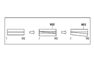
図8においては簡単の為に矢状面から見た上下の歯牙列を長方形で表した。802において上下の歯牙に幅1.5mmのスプリントを入れ、斜線部分を削ぎ取ったのが803である。802から803において下顎が第2臼歯を中心とした回転をし、切歯がもとの高さに戻る。臼歯-切歯間は40mmであるので803の切歯点において上下の歯牙のなす角θは
θ=tan-1(Z/40)=tan-1(1.5/40)=2.14°
と求まった。
In FIG. 8, the upper and lower tooth rows viewed from the sagittal plane are represented by rectangles for the sake of simplicity. In 802, a sprint having a width of 1.5 mm is put on the upper and lower teeth, and the hatched portion is scraped. From 802 to 803, the lower jaw rotates around the second molar, and the incisor returns to its original height. Since the distance between the molar and the incisor is 40 mm, the angle θ formed by the upper and lower teeth at the incision point 803 is θ = tan −1 (Z / 40) = tan −1 (1.5 / 40) = 2.14 °
I asked.
これより第2臼歯を原点とした下顎の任意の点(X,Z)のこの回転による移動後の座標(X’,Z’)は以下のようにして求められる。
また、第2臼歯を1.5mm高くすると切歯は3mm前方に移動するので、求める式は以下のようになる
X’=X×cosθ-Z×sinθ+3
Z’=X×sinθ+Z×cosθ+1.5
Thus, the coordinates (X ′, Z ′) after the movement of the arbitrary point (X, Z) of the lower jaw with the second molar as the origin can be obtained as follows.
Also, if the second molar is raised 1.5 mm, the incisor moves 3 mm forward, so the formula to be obtained is as follows: X ′ = X × cos θ−Z × sin θ + 3
Z ′ = X × sin θ + Z × cos θ + 1.5
これをもとにして、第2臼歯を1.5mm高くしたときの切歯と顆頭の移動後の座標を求めた結果は以下のようになる。
Based on this, the coordinates after the movement of the incisor and condyle when the second molar is raised 1.5 mm are as follows.
以上のように導出された式に対し、上述のように患者Xの上顎モデル及び下顎モデル、又はこれらを表すパラメータを適用することにより、患者Xが実際に行っている顎運動を導出することができる。例えば以上示したように、運動導出部120は、バーチャル咬合器再現の理論式及び顎内障の再現過程の理論式に従って偏心運動を導出することができる。POSTUROGRAFIAの機器類はこれらの問題を解決する糸口を示唆してくれた。POSTUGRAFIAは人間のバランスを支える複数の要素の関連性を診断したり、他にもRetinianas、感覚的な要因、眼球運動の要素 Propioceptivas、Oculomotrices等も考慮されている。人間がある一定の環境で自らの姿勢を維持する事が出来るのは、体の感覚受容器が外部の状況を察知するからであって、人間は外部の環境を理解する事が出来なければ姿勢を維持する事ができない。姿勢から眼球の運動Oculomotricidadは迷路前庭との関連性を見て、網膜の位置を決めたり、下半身では、頭部の前後・上下・左右の関係「exocaptore cefalicos」は、相互的に関連してきびす:足裏(踵:かかと)の位置等に関与している。
By applying the upper jaw model and lower jaw model of the patient X or parameters representing them to the expression derived as described above, the jaw movement actually performed by the patient X can be derived. it can. For example, as described above, the motion deriving unit 120 can derive the eccentric motion according to the theoretical formula of the virtual articulator reproduction and the theoretical formula of the process of regenerating the internal jaw. POSTUROGRAFIA equipment suggested clues to solve these problems. POSTUGRAFIA diagnoses the relevance of multiple elements that support human balance, and also considers Retinianas, sensory factors, eye movement elements Propioceptivas, Oculomotrices, etc. The reason why human beings can maintain their posture in a certain environment is because the sensory receptors of the body sense the external situation, and if humans cannot understand the external environment, posture Cannot be maintained. From the posture, the eye movement Oculomotricidad looks at the relationship with the labyrinth vestibule, determines the position of the retina, and in the lower body, the relationship between the front, back, top, bottom, left and right of the head "exocaptore cefalicos" is related to each other: Involved in the position of the sole (heel: heel).
出力部130は、運動導出部120が導出した偏心運動を示す情報を出力データ190として出力する。出力部130の出力方法としては、様々な方法を採用することができる。たとえば出力部130は、上顎と下顎との間の偏心運動を示す動画を出力しうる。特に出力部130は、歯を接触させながらの前方運動又は側方運動を示す動画を出力してもよい。出力部130が出力する動画においては、前方運動領域での運動が示されていてもよいし、後方運動領域での運動が示されていてもよい。
The output unit 130 outputs information indicating the eccentric motion derived by the motion deriving unit 120 as output data 190. Various methods can be adopted as the output method of the output unit 130. For example, the output unit 130 can output a moving image indicating the eccentric motion between the upper jaw and the lower jaw. In particular, the output unit 130 may output a moving image indicating a forward motion or a lateral motion while contacting the teeth. In the moving image output by the output unit 130, the motion in the forward motion region may be shown, or the motion in the backward motion region may be shown.
出力部130が出力する情報は動画に限られず、運動導出部120が導出した偏心運動に従う静止画像を出力してもよい。また、出力部130が生成する画像は、二次元画像でもよいし、三次元画像であってもよい。出力部130は、様々な方法で画像データを出力しうる。例えば画像出力部130は、ディスプレイ(不図示)を介して画像データを表示しうる。また画像出力部130は、入出力装置(不図示)を介して記憶媒体に画像データを格納してもよい。さらに、取得部110がデータを外部の装置から取得している場合には、画像出力部130は、この外部の装置に対して画像データを送信してもよい。
The information output by the output unit 130 is not limited to a moving image, and a still image according to the eccentric motion derived by the motion deriving unit 120 may be output. Further, the image generated by the output unit 130 may be a two-dimensional image or a three-dimensional image. The output unit 130 can output image data by various methods. For example, the image output unit 130 can display image data via a display (not shown). The image output unit 130 may store image data in a storage medium via an input / output device (not shown). Furthermore, when the acquisition unit 110 acquires data from an external device, the image output unit 130 may transmit the image data to the external device.
さらには、出力部130が出力する情報は、運動導出部120が導出した偏心運動の性質を示すパラメータであってもよい。例えば、Hobo S, Takayama H: Oral Rehabilitation clinical determination of Occlusion, 1997. Quintessence Publishing Co, Inc. で使用されているパラメータを、このパラメータとして用いることができる。この場合、運動導出部120は顎運動(偏心運動)そのものを導出するのではなく、患者Xが実際に行っている顎運動を示すパラメータを導出してもよい。
Furthermore, the information output from the output unit 130 may be a parameter indicating the nature of the eccentric motion derived by the motion deriving unit 120. For example, parameters used in Hobo S, Takayama H: Oral Rehabilitation clinical determination of Occlusion, 1997. Quintessence Publishing Co, Inc. can be used as this parameter. In this case, the motion deriving unit 120 may derive a parameter indicating the jaw motion actually performed by the patient X instead of deriving the jaw motion (eccentric motion) itself.
次に図2を参照して、本実施例に係る情報処理装置100が行う処理について説明する。図2は、情報処理装置100が行う処理を示すフローチャートである。
Next, processing performed by the information processing apparatus 100 according to the present embodiment will be described with reference to FIG. FIG. 2 is a flowchart illustrating processing performed by the information processing apparatus 100.
ステップS210において取得部110は、上述のように入力データ180を取得する。ステップS220において運動導出部120は、上述のように上顎モデルと下顎モデルとの間の偏心運動を導出する。ステップS230において出力部130は、運動導出部120が導出した偏心運動を示す出力データ190を出力する。
In step S210, the acquisition unit 110 acquires the input data 180 as described above. In step S220, the motion deriving unit 120 derives the eccentric motion between the upper jaw model and the lower jaw model as described above. In step S230, the output unit 130 outputs output data 190 indicating the eccentric motion derived by the motion deriving unit 120.
[実施例1の変形例]
実施例1において運動導出部120は、患者Xの上顎モデル及び下顎モデルを用いて、上顎と下顎との間の偏心運動を導出した。しかしながら、患者Xの上顎モデル及び下顎モデルをそのまま用いる必要はない。例えば歯科医師のようなユーザは、上顎モデル及び下顎モデルに対して、変形などの操作を加えることもできる。この操作には、例えば歯の形状を変えること、及びそれぞれの歯を移動させることが含まれる。
[Modification of Example 1]
In the first embodiment, the motion deriving unit 120 derives the eccentric motion between the upper jaw and the lower jaw using the upper jaw model and the lower jaw model of the patient X. However, it is not necessary to use the upper jaw model and lower jaw model of patient X as they are. For example, a user such as a dentist can also perform operations such as deformation on the upper jaw model and the lower jaw model. This operation includes, for example, changing the tooth shape and moving each tooth.
この場合、ユーザによって操作が加えられた後の上顎モデル及び下顎モデルが、入力データ180として情報処理装置100に入力されてもよい。また、取得部110が、ユーザからの指示を受けて、取得した入力データ180が示す上顎モデル及び下顎モデルを修正してもよい。
In this case, the upper jaw model and the lower jaw model after the operation is performed by the user may be input to the information processing apparatus 100 as the input data 180. In addition, the acquisition unit 110 may correct the upper jaw model and the lower jaw model indicated by the acquired input data 180 in response to an instruction from the user.
以下に、本発明の実施例2に係る情報処理装置について説明する。実施例2に係る情報処理装置101は、上顎と下顎との間の偏心運動と、患者の任意の顎運動とを比較することができる。本実施例に係る情報処理装置を、図1Bに示す。本実施例に係る情報処理装置101は実施例1に係る情報処理装置100と同様に、取得部110と、運動導出部120と、出力部130とを備える。本実施例に係る取得部110と運動導出部120とは、実施例1と同様に動作する。また出力部130は、比較部150の比較結果を出力する他は、実施例1と同様に動作する。このため、取得部110、運動導出部120、及び出力部130については説明を省略する。
Hereinafter, an information processing apparatus according to the second embodiment of the present invention will be described. The information processing apparatus 101 according to the second embodiment can compare the eccentric movement between the upper jaw and the lower jaw with an arbitrary jaw movement of the patient. An information processing apparatus according to the present embodiment is shown in FIG. 1B. Similar to the information processing apparatus 100 according to the first embodiment, the information processing apparatus 101 according to the present embodiment includes an acquisition unit 110, an exercise derivation unit 120, and an output unit 130. The acquisition unit 110 and the motion deriving unit 120 according to the present embodiment operate in the same manner as in the first embodiment. The output unit 130 operates in the same manner as in the first embodiment except that the comparison result of the comparison unit 150 is output. For this reason, description about the acquisition part 110, the exercise | movement derivation | leading-out part 120, and the output part 130 is abbreviate | omitted.
本発明の実施例2に係る情報処理装置101は、再生部140を有していてもよい。再生部140は、取得部110が取得した上顎の三次元モデルと下顎の三次元モデルとを用いて、患者Xの上顎と下顎との間の偏心運動を再生でき、再現もできる。顎運動の構築再生は、様々な方法によって行うことができる。例えば再生部140は、取得部110を介して、患者Xの顎運動を撮像することによって得られた動画像を取得してもよい。この動画像を解析することにより、患者Xの実際の顎運動を導出することができる。導出した顎運動に従って上顎の三次元モデルと下顎の三次元モデルとを動かすことにより、患者Xの顎運動を再生することができる。
The information processing apparatus 101 according to the second embodiment of the present invention may include the reproducing unit 140. The reproducing unit 140 can reproduce and reproduce the eccentric motion between the upper jaw and the lower jaw of the patient X using the upper jaw three-dimensional model and the lower jaw three-dimensional model acquired by the acquisition unit 110. The construction and reproduction of jaw movement can be performed by various methods. For example, the playback unit 140 may acquire a moving image obtained by imaging the jaw movement of the patient X via the acquisition unit 110. By analyzing this moving image, the actual jaw movement of the patient X can be derived. The jaw movement of the patient X can be reproduced by moving the upper jaw three-dimensional model and the lower jaw three-dimensional model in accordance with the derived jaw movement.
再生部140が再生・再現する偏心運動は、基準的な咬頭傾斜角に従う基準的な運動(基準運動)でありうる。例えば再生部140は、上述の前方運動理論式及び後方運動理論式に対して基準的な咬頭傾斜角を適用することにより、上顎と下顎との間の基準的な運動を再生・再現することができる。
The eccentric motion reproduced / reproduced by the reproducing unit 140 may be a standard motion (standard motion) according to a standard cusp inclination angle. For example, the reproduction unit 140 can reproduce and reproduce the standard movement between the upper jaw and the lower jaw by applying a standard cusp inclination angle to the above-described forward motion theory formula and backward motion theory formula. it can.
前方運動領域と後方運動領域とでは、異なる咬頭傾斜面の咬頭傾斜角を適用することができ、こうして前方運動領域における運動又は後方運動領域における運動を算出することができる。また、前方運動を導出する際と、側方運動を導出する際とで、異なる咬頭傾斜角を適用することができる。さらには、側方運動において作業側と非作業側とで、異なる咬頭傾斜角を適用することができる。ここで作業側とは、臼歯部の奥歯で咀嚼している側を指し、作業側においては歯牙の咬頭傾斜面が滑走している。また、作業側の反対側を、非作業側と呼ぶ。顆路を中心とする左右側のうち固定されている歯列弓側を作業側と呼ぶこともできる。この場合反対側の顆路の移動側を非作業側と呼び、下顎歯列弓が非作業側から作業側に移動しているという様に言うことができる。適用する咬頭傾斜角は全ての歯(全ての臼歯)について同一である必要はなく、それぞれの歯ごとに固有の異なる咬頭傾斜角を適用することもできる。エビデンス・ベースド・デンティストリーからなる診断においては、平均的な要素を踏まえていることが重要である。このような科学的な根拠の裏打ちをもって、ITH下顎運動理論式は顎運動を導出することができる。
In the forward movement area and the backward movement area, the cusp inclination angles of different cusp inclined surfaces can be applied, and thus the movement in the forward movement area or the movement in the backward movement area can be calculated. Also, different cusp tilt angles can be applied when deriving forward motion and when deriving lateral motion. Furthermore, different cusp inclination angles can be applied to the working side and the non-working side in the lateral movement. Here, the working side refers to the side that is chewed by the back teeth of the molar portion, and the cusp inclined surface of the tooth slides on the working side. The side opposite to the working side is referred to as the non-working side. Of the left and right sides centering on the condylar path, the fixed dental arch side can also be called the working side. In this case, the moving side of the opposite condylar path is called the non-working side, and it can be said that the lower dental arch is moving from the non-working side to the working side. The applied cusp angle does not have to be the same for all teeth (all molars), and a different cusp angle unique to each tooth can be applied. In diagnosis consisting of evidence-based dentistry, it is important to take into account the average factor. With the backing of this scientific basis, the ITH mandibular movement theory formula can derive the jaw movement.
適用する咬頭傾斜角は、例えば平均値的な趣旨に基づいて決定することができる。例えば、複数人についての咬頭傾斜角の平均値を用いることができる。もちろん、患者の属性(性別、年齢など)ごとの平均値を用いることもできる。
The applied cusp angle can be determined based on, for example, an average value. For example, the average value of the cusp inclination angle for a plurality of people can be used. Of course, an average value for each patient attribute (gender, age, etc.) can also be used.
適用できる咬頭傾斜角の一例を挙げると、例えば前方運動領域において、第一大臼歯の前方運動における矢状面の傾斜角は43°、側方運動における作業側の前頭面の傾斜角は25°、側方運動における非作業側の前頭面の傾斜角は34°でありうる。また、第二大臼歯の前方運動における矢状面の傾斜角は43°、側方運動における作業側の前頭面の傾斜角は25°、側方運動における非作業側の前頭面の傾斜角は35°でありうる。また、例えば後方運動領域において、上顎第二大臼歯の前方運動における矢状面の傾斜角は47°、側方運動における矢状面の傾斜角は40°でありうる。1歯の咬合面の形態もITH理論式からピンポイントに角度を算出できる。
As an example of applicable cusp inclination angle, for example, in the anterior movement region, the inclination angle of the sagittal plane in the forward movement of the first molar is 43 °, and the inclination angle of the frontal surface on the working side in the lateral movement is 25 °. The inclination angle of the non-working frontal surface in lateral movement may be 34 °. The inclination angle of the sagittal plane in the forward movement of the second molar is 43 °, the inclination angle of the frontal surface on the working side in the lateral movement is 25 °, and the inclination angle of the frontal surface on the non-working side in the lateral movement is It can be 35 °. For example, in the backward movement region, the inclination angle of the sagittal plane in the forward movement of the upper second molar can be 47 °, and the inclination angle of the sagittal plane in the lateral movement can be 40 °. The angle of the occlusal surface of one tooth can also be calculated as a pinpoint angle from the ITH theoretical formula.
再生部140が再生した偏心運動は、運動導出部120が導出した偏心運動と比較されるため、運動導出部120が導出した基準的な偏心運動に相当する、患者Xの顎の偏心運動を再生、再現することが好ましい。すなわち、運動導出部120が導出する偏心運動と、再生部140が再生する偏心運動とは、同種の運動であることが好ましい。同種の運動とは、例えば略同方向の運動でありうるし、略同領域での運動でありうる。たとえば、運動導出部120が前方運動領域での運動を導出するのならば、再生部140も前方運動領域での運動を再生することが好ましい。また、運動導出部120が側方運動を導出するのなら、再生部120も側方運動を再生、再現することが好ましい。
Since the eccentric motion reproduced by the reproducing unit 140 is compared with the eccentric motion derived by the motion deriving unit 120, the eccentric motion of the jaw of the patient X corresponding to the standard eccentric motion derived by the motion deriving unit 120 is reproduced. It is preferable to reproduce. That is, the eccentric motion derived by the motion deriving unit 120 and the eccentric motion reproduced by the reproducing unit 140 are preferably the same type of motion. The same type of motion can be, for example, motion in substantially the same direction, or motion in substantially the same region. For example, if the motion deriving unit 120 derives the motion in the forward motion region, it is preferable that the playback unit 140 also reproduces the motion in the forward motion region. In addition, if the motion deriving unit 120 derives the lateral motion, it is preferable that the reproducing unit 120 also reproduces and reproduces the lateral motion.
再生部140は、歯科医師のようなユーザから、上顎と下顎との間の運動に対する指示を取得してもよい。ユーザは、患者の顎運動を示す任意の指示を行うことができる。例えば再生部140は、取得部110が取得した上顎の三次元モデルと下顎の三次元モデルをユーザに対して表示してもよい。ユーザは表示された三次元モデルを見ながら、上顎と下顎との三次元モデルを自由に運動させることができる。こうしてユーザは、患者Xの上顎と下顎との間の偏心運動を再生することができる。ITH下顎運動理論式を用いて、各歯牙の咬頭傾斜面の角度を設定することができる。つまり、様々な顎運動に対しても、咬頭傾斜角度を設定することにより、より良い顎頭頚部の環境を再現できる。一方で以上のように再生された運動は、平均値的なデータに基づく基準的な運動における自由度を超越すると考えられる。これが、平均値が臨床エビデンスとなりうる所以である。1歯の咬合面の形態もITH理論式からピンポイントに角度を算出できる。
The reproducing unit 140 may acquire an instruction for movement between the upper jaw and the lower jaw from a user such as a dentist. The user can give any instruction that indicates the patient's jaw movement. For example, the reproducing unit 140 may display the upper jaw three-dimensional model and the lower jaw three-dimensional model acquired by the acquisition unit 110 to the user. The user can freely move the three-dimensional model of the upper jaw and the lower jaw while looking at the displayed three-dimensional model. Thus, the user can reproduce the eccentric motion between the upper jaw and the lower jaw of the patient X. The angle of the cusp inclined surface of each tooth can be set using the ITH mandibular movement theory. In other words, a better tempo-cervical environment can be reproduced by setting the cusp inclination angle for various jaw movements. On the other hand, it is considered that the motion reproduced as described above exceeds the degree of freedom in the standard motion based on the average value data. This is why the average value can be clinical evidence. The angle of the occlusal surface of one tooth can also be calculated as a pinpoint angle from the ITH theoretical formula.
実施例2に係る情報処理装置101は、比較部150をさらに備える。比較部150は、運動導出部120が導出した偏心運動と、上顎と下顎との間の基準的な運動とを比較することができる。この基準的な運動は、例えばユーザによって、予め設定された偏心運動であってもよい。情報処理装置101が再生部140を備える場合には、この基準的な運動として、再生部140が再生・再現した偏心運動を用いてもよい。すなわち比較部150は、運動導出部120が導出した偏心運動と、再生部140が再生・再現した偏心運動とを比較してもよい。以下、比較部150が、運動導出部120が導出した偏心運動と、再生部140が再生・再現した偏心運動とを比較する場合について説明する。しかしながら、比較部150が、運動導出部120が導出した偏心運動と、予め設定された偏心運動とを比較する場合についても同様である。比較は様々な方法によって行うことができる。例えば、運動の移動距離を比較しても良いし、運動の向きを比較しても良い。この場合、運動が一致するか否かを比較結果としてもよいし、運動がどの程度異なるかを比較結果としてもよい。特に比較部150は、前方運動領域と後方運動領域とのそれぞれについて、運動導出部120が導出した偏心運動と、予め設定された偏心運動又は再生部140が再生・再現した偏心運動とを比較することが好ましい。さらに比較部150は、前方運動と側方運動とのそれぞれについて、運動導出部120が導出した偏心運動と、予め設定された偏心運動又は再生部140が再生・再現した偏心運動とを比較することが好ましい。
The information processing apparatus 101 according to the second embodiment further includes a comparison unit 150. The comparison unit 150 can compare the eccentric motion derived by the motion deriving unit 120 with the standard motion between the upper jaw and the lower jaw. The standard exercise may be an eccentric exercise preset by the user, for example. When the information processing apparatus 101 includes the reproducing unit 140, an eccentric motion reproduced / reproduced by the reproducing unit 140 may be used as the reference motion. That is, the comparison unit 150 may compare the eccentric motion derived by the motion deriving unit 120 and the eccentric motion reproduced / reproduced by the reproduction unit 140. Hereinafter, a case where the comparison unit 150 compares the eccentric motion derived by the motion deriving unit 120 with the eccentric motion reproduced / reproduced by the reproduction unit 140 will be described. However, the same applies to the case where the comparison unit 150 compares the eccentric motion derived by the motion deriving unit 120 with a preset eccentric motion. The comparison can be done by various methods. For example, the movement distances of the exercises may be compared, and the directions of the exercises may be compared. In this case, it is good also as a comparison result whether exercise | movement corresponds, and it is good also as a comparison result how much exercise | movement differs. In particular, the comparison unit 150 compares the eccentric motion derived by the motion deriving unit 120 with the eccentric motion set in advance or reproduced / reproduced by the reproduction unit 140 for each of the forward motion region and the backward motion region. It is preferable. Further, the comparing unit 150 compares the eccentric motion derived by the motion deriving unit 120 with the eccentric motion set in advance or reproduced / reproduced by the reproducing unit 140 for each of the forward motion and the lateral motion. Is preferred.
さらには、上下顎1本ずつの傾斜面に対する接触の状況を、下顎歯列弓自体が理論式にのっとって運動する時の被蓋している1歯ずつの接触部位の削除、あるいは築成の手順に基づいて運動を比較することもできる。例えば、運動導出部120が導出した偏心運動と、再生部140が再生した偏心運動とのそれぞれについて、それぞれの歯が接触しているか否かを判断する。運動に伴って歯は接触したり離れたりする。そこで、歯が接触していく順序、歯が離れていく順序、あるいはこの双方を判断しても良い。運動導出部120が導出した偏心運動と、再生部140が再生し再現した偏心運動との間で、この順序が一致しているのなら、順序が一致していることを示す情報を出力しうる。また、この順序が異なっているのなら、順序が異なっていることを示す情報を出力しうるし、どの歯について順序が異なっているのかを示す情報を出力してもよい。
Furthermore, the state of contact with the inclined surfaces of the upper and lower jaws can be determined by deleting or constructing the contact site of each tooth covered when the lower dental arch itself moves according to the theoretical formula. You can also compare exercises based on procedures. For example, it is determined whether or not each tooth is in contact with each of the eccentric motion derived by the motion deriving unit 120 and the eccentric motion reproduced by the reproducing unit 140. Teeth come in contact with and move away with movement. Therefore, the order in which the teeth come in contact, the order in which the teeth move away, or both may be determined. If this order matches between the eccentric motion derived by the motion deriving unit 120 and the eccentric motion reproduced and reproduced by the playback unit 140, information indicating that the order matches can be output. . If the order is different, information indicating that the order is different may be output, and information indicating which tooth is different in order may be output.
上述のような歯の接触状態の評価は、実施例1に示したITH下顎運動理論式を利用することにより行うこともできる。また再生部140は、顎運動についての周知の比較手段を用いて、運動を比較してもよい。さらには比較部150は、運動導出部120が導出した偏心運動と、再生部140が再生した偏心運動との双方を、出力部130に出力させてもよい。この場合ユーザは、双方の偏心運動を比較することができる。
The evaluation of the contact state of the teeth as described above can also be performed by using the ITH mandibular movement theoretical formula shown in the first embodiment. Further, the reproduction unit 140 may compare movements using a well-known comparison unit for jaw movements. Furthermore, the comparison unit 150 may cause the output unit 130 to output both the eccentric motion derived by the motion deriving unit 120 and the eccentric motion reproduced by the reproduction unit 140. In this case, the user can compare both eccentric motions.
本実施例によれば、理論式に従う基準的な顎運動と、患者の顎運動とを、比較することができる。こうして、患者の顎運動と、基準的な顎運動との違いを判定することができる。本実施例によれば、各個人のデータからの情報と、エビデンスとしての平均値であらわされている基準値とを比較する事も可能である。また、平均値を基準値として用いることにより、各個人の本来あるべき正常な状況及び環境に、患者の歯牙を誘導するための評価情報を提供することができる。(参考文献:伊藤秀文、高山寿夫、噛み合わせの科学、第24巻、第1号、81頁、2004年)
According to this embodiment, it is possible to compare the standard jaw movement according to the theoretical formula and the patient's jaw movement. In this way, the difference between the patient's jaw movement and the standard jaw movement can be determined. According to the present embodiment, it is possible to compare information from each individual's data with a reference value represented by an average value as evidence. In addition, by using the average value as a reference value, it is possible to provide evaluation information for inducing the patient's teeth in the normal condition and environment that each person should have. (Reference: Hidefumi Ito, Toshio Takayama, Science of biting, Vol. 24, No. 1, p. 81, 2004)
[実施例2の変形例]
運動導出部120が顎運動そのものを導出するのではなく、患者Xが実際に行っている顎運動を示すパラメータを導出する場合、比較部150は、運動導出部120が導出したパラメータと、基準値とを比較してもよい。この基準値は、平均的な趣旨に基づいて予め決定されていてもよい。すなわち、臨床的に測定された複数人についての顎運動データから求められる、顎運動を示すパラメータの平均値を、この基準値として用いることができる。特にこの基準値は、基準的(平均的)な咬頭傾斜角に従う顎運動を示すパラメータであることが好ましい。もっともこの基準値は、理想的な運動を示すパラメータとして予めユーザによって決定された値であってもよい。
[Modification of Example 2]
When the motion deriving unit 120 does not derive the jaw motion itself but derives a parameter indicating the jaw motion actually performed by the patient X, the comparison unit 150 uses the parameter derived by the motion deriving unit 120 and the reference value. May be compared. This reference value may be determined in advance based on an average purpose. In other words, an average value of parameters indicating jaw movement obtained from clinically measured jaw movement data for a plurality of persons can be used as the reference value. In particular, the reference value is preferably a parameter indicating jaw movement according to a reference (average) cusp inclination angle. However, the reference value may be a value determined in advance by the user as a parameter indicating ideal exercise.
さらにはこの基準値は、患者の属性(性別、年齢など)に対応して設定された値であってもよい。例えばこの基準値は、患者の属性(性別、年齢など)ごとの、顎運動を示すパラメータの平均値であってもよい。この場合、取得部110は入力データ180の一部として患者の属性を取得してもよく、比較部150は取得部110が取得した患者の属性に対応する基準値を取得してもよい。
Furthermore, the reference value may be a value set corresponding to the patient's attributes (gender, age, etc.). For example, the reference value may be an average value of parameters indicating jaw movement for each patient attribute (gender, age, etc.). In this case, the acquisition unit 110 may acquire patient attributes as part of the input data 180, and the comparison unit 150 may acquire a reference value corresponding to the patient attributes acquired by the acquisition unit 110.
本変形例において比較部150は、この基準値を取得する。この基準値は、例えば再生部140に格納されていてもよい。すなわち再生部140は、平均的な顎運動を再生する代わりに、この平均的な顎運動を示すパラメータを比較部150に出力してもよい。もっとも比較部150は、この基準値をユーザから取得してもよい。
In the present modification, the comparison unit 150 acquires this reference value. This reference value may be stored in the reproduction unit 140, for example. That is, the reproducing unit 140 may output a parameter indicating the average jaw movement to the comparison unit 150 instead of reproducing the average jaw movement. But the comparison part 150 may acquire this reference value from a user.
そして比較部150は、運動導出部120が導出したパラメータと、基準値との比較結果を出力する。例えば比較部150は、運動導出部120が導出したパラメータと基準値との差を出力してもよい。また比較部150は、運動導出部120が導出したパラメータと基準値との差を、所定の閾値と比較してもよい。この場合比較部150は、この差が所定の閾値よりも大きいか、あるいは所定の閾値よりも小さいすなわち差がほとんどないか、を示す情報を出力してもよい。
Then, the comparison unit 150 outputs a comparison result between the parameter derived by the motion deriving unit 120 and the reference value. For example, the comparison unit 150 may output the difference between the parameter derived by the motion deriving unit 120 and the reference value. The comparison unit 150 may compare the difference between the parameter derived by the motion deriving unit 120 and the reference value with a predetermined threshold value. In this case, the comparison unit 150 may output information indicating whether the difference is larger than a predetermined threshold value or smaller than the predetermined threshold value, that is, whether there is almost no difference.
さらに比較部150は、運動導出部120が導出したパラメータが複数ある場合、それぞれのパラメータを対応する基準値と比較してもよい。この場合比較部150は、どのパラメータが基準値と乖離しているかを示す情報を出力してもよい。あるパラメータが基準値と乖離しているか否かは、パラメータと基準値との差を所定の閾値と比較することにより行うことができる。
Furthermore, when there are a plurality of parameters derived by the motion deriving unit 120, the comparing unit 150 may compare each parameter with a corresponding reference value. In this case, the comparison unit 150 may output information indicating which parameter is deviated from the reference value. Whether or not a parameter deviates from the reference value can be determined by comparing the difference between the parameter and the reference value with a predetermined threshold value.
実施例2と同様に比較部150は、前方運動領域と後方運動領域とのそれぞれについて、運動導出部120が導出したパラメータと基準値とを比較することが好ましい。さらに比較部150は、前方運動と側方運動とのそれぞれについて、運動導出部120が導出したパラメータと基準値とを比較することが好ましい。また、前方運動領域と後方運動領域とで異なる基準値が設定されていてもよいし、前方運動と側方運動とで異なる基準値が設定されていてもよい。さらには、側方運動において、作業側と非作業側とについて顎運動を示すパラメータが独立に求められてもよい。この場合、作業側と非作業側とについて異なる基準値が設定されていてもよく、それぞれのパラメータは対応する基準値と比較されてもよい。
As in the second embodiment, the comparison unit 150 preferably compares the parameter derived by the motion deriving unit 120 with the reference value for each of the forward motion region and the backward motion region. Furthermore, it is preferable that the comparison unit 150 compares the parameter derived by the motion deriving unit 120 with the reference value for each of the forward motion and the lateral motion. Further, different reference values may be set for the forward motion area and the backward motion area, or different reference values may be set for the forward motion and the lateral motion. Furthermore, in the lateral movement, parameters indicating jaw movement may be obtained independently for the working side and the non-working side. In this case, different reference values may be set for the working side and the non-working side, and each parameter may be compared with the corresponding reference value.
比較することにより、過去・現在・未来の治療の方針を定める対策を包括しうる。こうして、請求項の理論式を総合企画されたプログラムをあらゆる他社のシステム機器に連動できる。また、4Dからひとつずつ条件を加えることで次元の拡大を可能にできる情報処理装置、情報処理方法、及びプログラムが実現できる。多次元定義を図10に示す。すなわち、4Dの構想は、ITH顎運動理論式も基準にして各患者の個人データを解析して現在の咬合を再現する。5Dは、過去・現在・未来の経時的変化を再現し、機能性としての判断が総合的にできる。6Dは、現在の状況が過去においてどのような経過でもって進行しているかの原因を特定する事と、現在から将来(未来)の予防方法を適確に診断する。7Dは、原因の特定、予防方法から治療方法に至り、結果の予測をする。8Dは、その結果予測から、患者自身の五感である感覚受容器への伝達のための対策である。ここで、治療のための診断対策が取り入れられて治療方針が位置づけられる。3-Shapeの医療に使用されている機器が存在しているが、今回のものは、歯科の感覚受容器としての範疇である。
By comparing, it is possible to include measures that define past, present, and future treatment policies. In this way, the program that comprehensively plans the theoretical formula of claims can be linked to system devices of other companies. In addition, an information processing apparatus, an information processing method, and a program capable of expanding dimensions by adding conditions one by one from 4D can be realized. The multidimensional definition is shown in FIG. That is, the 4D concept reproduces the current occlusion by analyzing each patient's personal data based on the ITH jaw movement theory. 5D reproduces changes over time in the past, present, and future, and can comprehensively judge functionality. 6D identifies the cause of how the current situation is progressing in the past, and accurately diagnoses the preventive method from the present to the future (future). 7D leads from the identification of the cause and the prevention method to the treatment method, and predicts the result. 8D is a measure for transmitting the result to a sensory receptor that is the patient's own five senses based on the prediction. Here, the diagnostic policy for treatment is taken in and the treatment policy is positioned. There are devices used in 3-Shape's medicine, but this time is a category as a dental sensory receptor.
言い換えれば本実施例に記載の技術に従えば、過去・現在・未来の前記偏心運動の経時的変化を再現する5次元の機能と、過去において状況がどのように進行して現在に至ったのか原因を特定して現在から将来への予防方法を診断する6次元の機能と、前記原因の特定及び前記予防方法に従って治療方法を提示し該治療方法による結果の予測を行う7次元の機能と、該結果の予測に従って患者自身の五感である感覚受容器への伝達方法を提示する8次元の機能と、を実現しうる。このような機能は、上に示したようなITH総合企画顎顔面運動理論式によって、またはこの理論式を含むプログラムによって実現しうる。
In other words, according to the technique described in the present embodiment, the five-dimensional function that reproduces the temporal change of the eccentric motion in the past, the present, and the future, and how the situation progressed in the past to the present. A 6-dimensional function for identifying the cause and diagnosing a preventive method from the present to the future, a 7-dimensional function for identifying the cause and presenting a treatment method according to the preventive method, and predicting a result by the treatment method; According to the prediction of the result, it is possible to realize an eight-dimensional function that presents a transmission method to a sensory receptor that is the patient's own five senses. Such a function can be realized by the ITH comprehensive plan maxillofacial motion theoretical formula as shown above or by a program including this theoretical formula.
高山の下顎運動理論式の再評価をすることで、誤りを提示することができ後方運動の理論式を考察し、ITH下顎運動理論式を導出することができた。今後、一般歯科、矯正歯科分野等で、咬合器に上下顎歯列模型を装着して診断する方法と、顎頭頚部領域を含めたコンピュータによる画像システム(3D・4D)により、治療のための手順が分かりやすく説明できる。さらなるエビデンス・ベースド・メディスンの確立に貢献することになればと考える。近年の全世界各社のCAD・CAM機器は、スキャンニング等の精度は、工業界の寸法数値に限りなく近づいてきた。
By re-evaluating the theory of mandibular movement of Takayama, it was possible to present an error, to consider the theoretical formula of backward movement, and to derive the theoretical formula of ITH mandibular movement. In the future, in the field of general dentistry, orthodontic dentistry, etc., a method for diagnosis by attaching an upper and lower jaw dentition model to an articulator and a computerized image system (3D / 4D) including the maxillotemporal neck region will be used for treatment. Explain the procedure in an easy to understand manner. I hope to contribute to the establishment of further evidence-based medicine. In recent years, CAD / CAM devices of various companies all over the world have approached the accuracy of scanning and the like as much as possible in the industry.
最近世界各国でCAD・CAMの機械が工業製品から医療界に進出し、現在、企業の矛先は(歯科医と技工士に対して向けられているが)量産体制を見越した機器類に変貌している。某大手の補綴の製作工程をみても、一貫性のある治療方式を理解させようとしているように見えて、歯科医と技工士の匠に頼らざるを得ない。寸法精度はかなり良くなり、シロナ(モリタ販売)「DEREC AC」は、Biogenericと言う精確な測定原理に基づいて、個々の歯の状態を一瞬にして計量的分析から咬合面の形態を再現する(短波長青色LED)。他社のCAD・CAMである「3 Shape Dental System」、3Mの「COS(チェアサイド、オーラル、スキャナー)」も最新機器としての高精度管理は、抜群である。但し、一般歯科医が修復物の治療をしてしまった経緯は、説明どころか、診断すらもできていない。つまり、究極の診断がないのである。診断と治療は、一体性のある統合的概念であるべきである。
Recently, CAD / CAM machines have entered the medical field from industrial products in various countries around the world, and now the company's contradictions (although it is aimed at dentists and technicians) have been transformed into equipment that anticipates mass production. ing.某 Looking at the major prosthesis production process, it seems that they are trying to understand a consistent treatment system, and they have to rely on dentists and technicians. Dimensional accuracy is considerably improved, and Sirona (Morita sales) “DEREC AC” reproduces the shape of the occlusal surface from the quantitative analysis based on the precise measurement principle called “Biogeneric” by instantaneously analyzing the state of each tooth ( Short wavelength blue LED). The other companies' CAD / CAM “3 Shape DentalCOSystem” and 3M ’s “COS (Chairside, Oral, Scanner)” are also excellent in high-precision management as the latest equipment. However, the reason why the general dentist treated the restoration was not able to explain or even make a diagnosis. In short, there is no ultimate diagnosis. Diagnosis and treatment should be an integrated and integrated concept.
一般の歯科治療は、試行錯誤法に準じて執り行われているのが現状である。歯科医と患者は、エビデンスに則り同じレベルで対等な関係でなくてはいけない。科学的な根拠と数十年の臨床知見、患者の知識レベルの同意のもとで、診断と治療には一体性をもたせるべきである。
At present, general dental treatment is performed according to the trial and error method. The dentist and patient must be at the same level and in equal relations according to the evidence. Based on scientific evidence, decades of clinical knowledge, and agreement on the level of patient knowledge, diagnosis and treatment should be united.