WO2012017940A1 - 便器洗浄装置 - Google Patents
便器洗浄装置 Download PDFInfo
- Publication number
- WO2012017940A1 WO2012017940A1 PCT/JP2011/067429 JP2011067429W WO2012017940A1 WO 2012017940 A1 WO2012017940 A1 WO 2012017940A1 JP 2011067429 W JP2011067429 W JP 2011067429W WO 2012017940 A1 WO2012017940 A1 WO 2012017940A1
- Authority
- WO
- WIPO (PCT)
- Prior art keywords
- water
- jet
- rim
- water supply
- cleaning
- Prior art date
- Legal status (The legal status is an assumption and is not a legal conclusion. Google has not performed a legal analysis and makes no representation as to the accuracy of the status listed.)
- Ceased
Links
Images





Classifications
-
- E—FIXED CONSTRUCTIONS
- E03—WATER SUPPLY; SEWERAGE
- E03D—WATER-CLOSETS OR URINALS WITH FLUSHING DEVICES; FLUSHING VALVES THEREFOR
- E03D5/00—Special constructions of flushing devices, e.g. closed flushing system
- E03D5/10—Special constructions of flushing devices, e.g. closed flushing system operated electrically, e.g. by a photo-cell; also combined with devices for opening or closing shutters in the bowl outlet and/or with devices for raising/or lowering seat and cover and/or for swiveling the bowl
-
- E—FIXED CONSTRUCTIONS
- E03—WATER SUPPLY; SEWERAGE
- E03D—WATER-CLOSETS OR URINALS WITH FLUSHING DEVICES; FLUSHING VALVES THEREFOR
- E03D11/00—Other component parts of water-closets, e.g. noise-reducing means in the flushing system, flushing pipes mounted in the bowl, seals for the bowl outlet, devices preventing overflow of the bowl contents; devices forming a water seal in the bowl after flushing, devices eliminating obstructions in the bowl outlet or preventing backflow of water and excrements from the waterpipe
- E03D11/02—Water-closet bowls ; Bowls with a double odour seal optionally with provisions for a good siphonic action; siphons as part of the bowl
-
- E—FIXED CONSTRUCTIONS
- E03—WATER SUPPLY; SEWERAGE
- E03D—WATER-CLOSETS OR URINALS WITH FLUSHING DEVICES; FLUSHING VALVES THEREFOR
- E03D11/00—Other component parts of water-closets, e.g. noise-reducing means in the flushing system, flushing pipes mounted in the bowl, seals for the bowl outlet, devices preventing overflow of the bowl contents; devices forming a water seal in the bowl after flushing, devices eliminating obstructions in the bowl outlet or preventing backflow of water and excrements from the waterpipe
- E03D11/02—Water-closet bowls ; Bowls with a double odour seal optionally with provisions for a good siphonic action; siphons as part of the bowl
- E03D11/08—Bowls with means producing a flushing water swirl
-
- E—FIXED CONSTRUCTIONS
- E03—WATER SUPPLY; SEWERAGE
- E03D—WATER-CLOSETS OR URINALS WITH FLUSHING DEVICES; FLUSHING VALVES THEREFOR
- E03D2201/00—Details and methods of use for water closets and urinals not otherwise provided for
- E03D2201/30—Water injection in siphon for enhancing flushing
Definitions
- the present invention relates to a toilet bowl cleaning device.
- Patent Document 1 discloses a conventional toilet cleaning device. This toilet cleaning device supplies cleaning water to the toilet body.
- the toilet bowl body has a stool part, a rim water channel provided at the inner peripheral edge of the upper end of the stool part, a rim water outlet that discharges wash water along the rim water channel, and continuous downstream of the toilet bowl part. And a jet spout for discharging washing water toward the downstream side of the toilet drainage channel.
- the toilet bowl cleaning device has a valve unit.
- This valve unit has a rim on-off valve and a jet on-off valve.
- the upstream side of the rim on-off valve and the jet on-off valve communicates with a water supply source through a water supply path.
- the downstream side of the rim on-off valve communicates with the rim water spouting port via the rim-side water supply channel.
- the downstream side of the jet on / off valve communicates with the jet water spouting port via the jet side water supply passage.
- a pressure accumulator for storing wash water in a pressure accumulation state communicates with the water supply channel.
- the wash water flows into the tank, and the wash water can be stored in a pressure accumulation state by the hydrostatic pressure. Further, when the rim on-off valve or the jet on-off valve is opened, the accumulator flows out the wash water stored in the tank in a pressure-accumulated state and adds it to the wash water supplied from the water supply source. Wash water can be discharged from the water outlet.
- This toilet flushing device discharges flush water in the order of the rim spout, the jet spout, and the rim spout when flushing the flush water from the rim spout and the jet spout and performing toilet cleaning.
- the water stored in the accumulator tank in the pressure accumulation state was supplied from the water supply source. Add to wash water.
- cleaning apparatus discharges the whole quantity of the wash water stored in the pressure accumulation tank in the pressure accumulation state by the discharge of the wash water from the first rim spout.
- this toilet flushing device closes the rim on-off valve and the jet on-off valve before starting the discharge of the wash water from the jet spout, and again in the pressure accumulation state in the tank of the accumulator. Store wash water. Then, this toilet bowl washing
- Soil and the like can be discharged best from the road.
- this toilet bowl cleaning device since there is a time lag between the end of the water discharge from the first rim spout and the start of the water discharge from the jet spout, the water discharge from the jet spout At the time of starting, the water level of the wash water in the toilet bowl is lowered from the maximum water level. For this reason, this toilet bowl washing
- the present invention has been made in view of the above-described conventional situation, and provides a toilet cleaning device that is excellent in discharging performance of filth and the like and can perform toilet cleaning satisfactorily even with a small amount of cleaning water. This is a problem to be solved.
- the toilet bowl cleaning device of the present invention includes a toilet bowl portion, a rim water passage provided at an inner peripheral edge of the upper end opening of the toilet bowl portion, a rim water outlet for discharging washing water along the rim water passage, and the toilet bowl A toilet flushing device that supplies flush water to a toilet body having a toilet drainage channel provided continuously downstream of the unit and a jet spout for discharging flush water toward the downstream side of the toilet drainage channel.
- a water supply channel for supplying cleaning water to the rim water spouting port and the jet water spouting port;
- the water is first discharged from the rim water outlet and then the jet water outlet continuously.
- a water supply switching mechanism for switching the water supply destination so as to discharge the wash water from The cleaning water stored in the tank has a tank that communicates with the water supply channel and stores cleaning water, and the cleaning water discharged from the rim water spouting port and the jet water spouting port has a flow rate equal to or higher than a set value.
- a flow rate amplifying mechanism for discharging a part of the water from the rim water spouting port and the remaining part from the jet water spouting port.
- this toilet flushing device uses a rim spout and a jet spout to discharge the wash water from the rim spout while maintaining the flow rate of the wash water spouted from the rim water spout and the jet spout.
- the washing water can be continuously discharged. Therefore, it is possible to start discharging the cleaning water from the jet water outlet while the cleaning water level in the toilet bowl is at the highest water level by discharging the cleaning water from the rim water outlet.
- the washing water can be discharged from the jet spout while the potential energy of the washing water in the toilet bowl is maximized, the maximum potential energy of the cleaning water in the toilet bowl and the jet spout are discharged.
- the flow rate refers to the amount of water that passes per unit time.
- the toilet bowl cleaning device of the present invention is excellent in discharging performance of filth and the like, and can perform toilet bowl cleaning even with a small amount of cleaning water.
- the flow rate amplification mechanism of the present invention may be a pressure accumulator.
- This pressure accumulator has a tank whose volume is increased by the washing water flowing in from the water supply channel, and an elastic body which gives an elastic force in a direction of decreasing the volume of the tank.
- this pressure accumulator can store the wash water in a pressure-accumulated state while expanding the tank volume against the elastic force of the elastic body by the hydrostatic pressure of the wash water. it can.
- the pressure accumulator can add the cleaning water stored in the tank in a pressure accumulation state to the cleaning water flowing through the water supply channel.
- the pressure accumulator can amplify the flow rate of the cleaning water discharged from the rim water spouting port and the jet water spouting port with no power source to a set value or more.
- the flow rate amplification mechanism of the present invention may be composed of a tank and a pump. In this case, by driving the pump so that the flow rate becomes equal to or higher than the set value, the wash water stored in the tank flows out, and the flow rate of the wash water discharged from the rim water spouting port and jet water spout is amplified above the set value. can do.
- the initial flow rate of the wash water discharged from the jet water spouting port may be larger than the flow rate of the wash water discharged from the rim water discharge port.
- the wash water stored in the tank can be appropriately distributed to the rim water spouting port and the jet water spouting port and discharged. That is, the wash water discharged from the jet spout is used to discharge filth and the like from the toilet drainage channel by generating a siphon action in the toilet drainage channel due to the water force. For this reason, it is preferable that the washing water discharged from the jet water outlet spouts as vigorously as possible at the beginning of the water discharge.
- the wash water discharged from the rim spout is intended to wash the surface of the toilet bowl part evenly, and the surface of the toilet bowl part is weaker than the initial water flow of the wash water discharged from the jet spout. Can be washed evenly.
- the amount of the remaining wash water stored in the tank discharged from the jet outlet is larger than the amount of the wash water stored in the tank discharged from the rim outlet, and the jet The amount of cleaning water discharged from the water outlet can be larger than the amount of cleaning water discharged from the rim water outlet.
- the wash water stored in the tank can be appropriately distributed to the rim water spouting port and the jet water spouting port and discharged. That is, the wash water discharged from the jet outlet is used to discharge filth and the like from the toilet drainage channel by generating and continuing a siphon action in the toilet drainage channel. For this reason, it is preferable that the washing water discharged from the jet water outlet is as large as possible.
- the wash water discharged from the rim spout is intended to clean the surface of the toilet bowl part evenly, and even if the amount of the wash water discharged from the jet spout is less than the surface of the toilet bowl part It can be washed evenly.
- the water supply channel is composed of an upstream water supply channel communicating with a water supply source, and a jet-side water supply channel and a rim-side water supply channel formed by branching the downstream end of the upstream water supply channel,
- the flow rate amplifying mechanism can communicate with the jet side water supply channel.
- the water supply switching mechanism includes: a jet on / off valve that opens and closes the jet side water supply path; a rim on / off valve that opens and closes the rim side water supply path; and the jet on / off valve and the rim open / close valve that opens and closes.
- Control device to control The flow rate amplifying mechanism is communicated with the jet side water supply channel upstream of the jet on / off valve, and is provided in the jet side water supply channel upstream of the communication portion communicating with the flow rate amplifying mechanism.
- a flow rate adjusting valve that allows a large flow rate to the downstream side of the water supply channel and allows a small flow rate to the upstream side may be provided.
- the flow rate adjusting valve can reduce the flow rate of the cleaning water flowing out from the flow rate amplification mechanism when the cleaning water is discharged from the rim water spouting port rather than when the cleaning water is discharged from the jet water spouting port. Therefore, the initial flow rate of the cleaning water discharged from the jet spouting port is made larger than the flow rate of the cleaning water discharged from the rim spouting port, or the amount of the cleaning water discharged from the jet spouting port is discharged from the rim spouting port. Increasing the amount of water than the amount of water can be easily realized with a simple structure.
- the toilet bowl cleaning device 10 of the embodiment supplies cleaning water to the toilet bowl body 1.
- the toilet body 1 includes a toilet bowl 2, a rim water passage 3, a rim water discharge port 4A, a toilet drainage channel 6, and a jet water discharge port 7A.
- the toilet body 1 is provided with a rim water passage 3 in a shelf shape on the inner peripheral edge of the upper end opening of the toilet bowl 2.
- the rim water spouting port 4 ⁇ / b> A is opened at the front end surface of the rim nozzle 4.
- the rim nozzle 4 is disposed at the left rear corner of the toilet bowl 2 as viewed from the front end F side of the toilet bowl 2.
- the rim nozzle 4 is connected to the downstream end of the rim-side water supply pipe 5A that forms a part of the rim-side water supply path.
- the wash water discharged from the rim water spouting port 4 ⁇ / b> A flows down into the stool part 2 while turning around the upper edge of the stool part 2 along the rim water passage 3 in one direction. For this reason, when the wash water is discharged from the rim spout 4A, the level of the wash water in the stool part 2 rises while forming a swirling flow toward the center part in the stool part 2.
- the toilet body 1 is provided with a toilet drainage channel 6 continuously downstream of the toilet bowl 2.
- the toilet drainage channel 6 includes an ascending channel extending rearward and obliquely upward from the lower portion of the toilet bowl 2, and a descending channel bent from the upper end of the ascending channel and extending vertically downward. ing.
- the jet spout 7A is opened at the front end surface of the jet nozzle 7.
- the jet nozzle 7 is attached to the upstream lower end of the ascending flow path of the toilet drainage channel 6.
- the jet nozzle 7 is connected to a downstream end portion of a jet-side water supply pipe 8A that forms a part of the jet-side water supply path. Wash water discharged from the jet spout 7 ⁇ / b> A flows downstream of the toilet drainage channel 6 while filling the rising channel of the toilet drainage channel 6.
- the toilet bowl cleaning device 10 includes a valve unit 20 that is a water supply switching mechanism and a pressure accumulator 30 that is a flow rate amplification mechanism, as shown in FIGS. 1, 3, and 4.
- cleaning apparatus 10 are attached to the rear part of the toilet bowl main body 1, and the upper part and the side are covered with the upper cover 11C and the lower cover which is not shown in figure.
- the upper cover 11C is attached to the upper rear part of the toilet body 1, and pivotally supports the toilet seat 11A and the toilet lid 11B.
- the lower cover is attached to the rear side surface of the toilet body 1.
- the valve unit 20 includes an upstream channel 9B, a jet channel 8B formed by branching the downstream end of the upstream channel 9B, and a rim channel 5B.
- the upstream channel 9B extends in the vertical direction.
- the jet-side channel 8B extends in the horizontal direction from the upper end, which is the downstream end of the upstream-side channel 9B, then bends upward, and extends in the vertical direction via the jet on-off valve 21.
- the rim side channel 5B extends from the upper end, which is the downstream end of the upstream channel 9B, in the direction opposite to the portion extending in the horizontal direction of the jet side channel 8B, and then bends upward, thereby opening and closing the rim opening / closing valve. It extends in the vertical direction via 22.
- the upstream flow passage 9B has an upstream connecting portion 9C formed at the lower portion which is the upstream end.
- the upstream connecting portion 9C is connected to a water supply pipe 9A that communicates with a water supply source.
- the upstream water supply channel is configured by the upstream channel 9B, the upstream connecting portion 9C, and the water supply pipe 9A.
- the upstream flow path 9 ⁇ / b> B accommodates the strainer 25.
- the strainer 25 can be attached and detached from the lower end of the upstream flow path 9B.
- a check valve 26 is arranged at the upper end portion which is the downstream end. The check valve 26 allows the wash water to flow from the upstream side to the downstream side and can prevent the reverse flow.
- the jet side flow path 8B has a jet side connecting portion 8C formed at the upper part which is the downstream end.
- the jet side connecting portion 8C is connected to the jet side water supply pipe 8A.
- the jet side water supply path is configured by the jet side flow path 8B, the jet side connection portion 8C, and the jet side water supply pipe 8A.
- the water supply path which supplies washing water to the jet spout 7A is comprised by the upstream water supply path and the jet side water supply path.
- the jet-side flow path 8B is a portion extending in the horizontal direction from the upper end portion of the upstream flow path 9B, and houses the flow rate adjusting valve 23 on the upstream side from the bent portion C bent upward.
- the flow rate adjusting valve 23 is elastic in the direction in which the adjusting valve main body 23A contacts the valve seat 8D from the downstream side with the valve seat 8D provided by expanding the jet-side flow path 8B, and the adjusting valve main body 23A contacts the valve seat 8D.
- a coil spring 23C for applying a force.
- the adjustment valve main body 23A has a small hole 23B provided therethrough. When the cleaning water flows from the upstream side to the downstream side, the adjustment valve main body 23A is separated from the valve seat portion 8D.
- the flow rate adjustment valve 23 allows a flow of a large flow rate to the downstream side of the jet side water supply channel.
- the adjusting valve main body 23A is seated on the valve seat portion 8D, and the cleaning water flows only through the small hole 23B.
- the flow rate adjusting valve 23 allows a small flow rate to the upstream side of the jet side water supply channel.
- the jet-side flow path 8B forms a communicating portion 27 that communicates with the pressure accumulator 30 via the water supply / drain pipe 31 at the lower end of the bent portion C. Further, the jet-side flow path 8B forms a local cleaning water supply path S for supplying cleaning water to a local cleaning device (not shown) on the side surface of the bent portion C.
- the jet-side flow path 8B is downstream of the bent portion C, and is provided with a jet on-off valve 21 that opens and closes the jet-side water supply channel at the lower portion of the portion extending in the vertical direction.
- the jet on / off valve 21 includes a diaphragm-type first main valve 21A, a first valve seat 21B to which the first main valve 21A is attached and detached, a first back pressure chamber 21C formed behind the first main valve 21A, a first A first drain passage 21D that communicates the back pressure chamber 21C and the secondary side of the first main valve 21A, a first pilot valve 21E that opens and closes the first drain passage 21D, and a first pilot that drives the first pilot valve 21E to open and close A solenoid 21F is provided.
- the first main valve 21A has a first small hole 21G that communicates the first back pressure chamber 21C and the primary side of the first main valve 21A.
- the first solenoid 21F is driven based on an open / close signal transmitted from the control
- the jet on / off valve 21 configured in this way opens and closes the jet-side water supply channel as described below.
- the first solenoid 21F receives a valve opening signal from the control device 24, the first solenoid 21F is driven and the first pilot valve 21E opens the first drainage channel 21D.
- the wash water in the first back pressure chamber 21C is drained from the first drainage channel 21D to the secondary side of the first main valve 21A.
- the pressure of the washing water applied to the surface opposite to the surface of the first main valve 21A on the first back pressure chamber 21C side becomes higher, and the first main valve 21A separates from the first valve seat 21B.
- the jet on-off valve 21 is opened.
- the first solenoid 21F receives the valve closing signal from the control device 24, the first solenoid 21F is driven and the first pilot valve 21E closes the first drain passage 21D. Then, washing water flows into the first back pressure chamber 21C from the primary side of the first main valve 21A through the first small hole 21G. Thereby, the surface of the first main valve 21A on the first back pressure chamber 21C side is higher than the pressure of the washing water applied to the opposite surface, and the first main valve 21A is seated on the first valve seat 21B. Thus, the jet on-off valve 21 is closed.
- a jet side air release valve 28A is provided at the upper end of the jet side flow path 8B.
- the jet-side air release valve 28A is open to the atmosphere when washing water is not discharged from the jet water outlet 7A via the jet-side water supply channel, and opens downstream from the jet-side air release valve 28A to the atmosphere. .
- the rim side channel 5B has a rim side connecting portion 5C formed at the upper part which is the downstream end.
- the rim side connecting portion 5C is connected to the rim side water supply pipe 5A.
- the rim-side water supply path is configured by the rim-side flow path 5B, the rim-side connecting portion 5C, and the rim-side water supply pipe 5A.
- the upstream water supply channel and the rim-side water supply channel constitute a water supply channel that supplies cleaning water to the rim water spouting port 4A.
- the rim side channel 5B houses a lid member 29 in a portion extending in the horizontal direction from the upper end of the upstream channel 9B.
- the lid member 29 has a cylindrical shape with one end (the right side in FIG. 3) closed, and a plurality of openings 5D are provided on the side surface so that cleaning water flows from the inside to the outside. The washing water that has flowed out of the opening 5D flows into the rim-side channel 5B that extends in the vertical direction.
- the lid member 29 can be attached to and detached from the rim side channel 5B. For this reason, the lid member 29 can be removed from the rim-side flow path 5B, and the flow rate adjusting valve 23 can be stored in the jet-side flow path 8B or removed for maintenance.
- the rim side flow path 5B is provided with a rim opening / closing valve 22 for opening and closing the rim side water supply path at the lower part of the portion extending in the vertical direction.
- the rim on-off valve 22 includes a diaphragm-type second main valve 22A, a second valve seat 22B to which the second main valve 22A is attached and detached, a second back pressure chamber 22C formed behind the second main valve 22A, a second A second drain passage 22D that communicates the back pressure chamber 22C and the secondary side of the second main valve 22A, a second pilot valve 22E that opens and closes the second drain passage 22D, and a second pilot valve 22E that opens and closes the second pilot valve 22E.
- a solenoid 22F is provided.
- the second main valve 22A has a second small hole 22G that communicates the second back pressure chamber 22C and the primary side of the second main valve 22A.
- the second solenoid 22F is driven based on an open / close signal transmitted from the control device 24.
- the rim opening / closing valve 22 configured in this way opens and closes the rim-side water supply channel as described below.
- the second solenoid 22F receives the valve opening signal from the control device 24, the second solenoid 22F is driven and the second pilot valve 22E opens the second drainage channel 22D.
- the wash water in the second back pressure chamber 22C is drained from the second drainage channel 22D to the secondary side of the second main valve 22A.
- the pressure of the washing water applied to the surface opposite to the second back pressure chamber 22C side of the second main valve 22A becomes higher, and the second main valve 22A is separated from the second valve seat 22B and the rim.
- the on-off valve 22 is opened.
- the second solenoid 22F receives a valve closing signal from the control device 24, the second solenoid 22F is driven and the second pilot valve 22E closes the second drainage channel 22D. Then, washing water flows into the second back pressure chamber 22C from the primary side of the second main valve 22A through the second small hole 22G. Thereby, the surface of the second main valve 22A on the second back pressure chamber 22C side becomes higher than the pressure of the washing water applied to the opposite surface, and the second main valve 22A is seated on the second valve seat 22B. Then, the rim on-off valve 22 is closed.
- a rim-side air release valve 28B is provided at the upper end of the rim-side flow path 5B.
- the rim-side air release valve 28B is open to the atmosphere when the wash water is not discharged from the rim spout 4A via the rim-side water supply channel, and opens downstream from the rim-side air release valve 28B to the atmosphere. . This prevents the sewage on the secondary side from the rim atmosphere release valve 28 ⁇ / b> B from flowing back to the primary side from the rim opening / closing valve 22.
- the pressure accumulator 30 includes a partition wall 32 that reciprocates, and has a tank 33 that increases and decreases the volume by the reciprocation of the partition wall 32.
- the pressure accumulator 30 includes a coil spring 34 that applies an elastic force to the partition wall 32 in a direction that reduces the volume of the tank 33. For this reason, the tank 33 of the pressure accumulator 30 can store the wash water in a pressure-accumulated state while expanding the volume when the wash water flows in through the water supply / drain pipe 31.
- the toilet flushing apparatus 10 closes the jet on-off valve 21 and the rim on-off valve 22.
- the wash water flowing into the valve unit 20 from the water supply pipe 9A communicated with the water supply source is the upstream connecting portion 9C, the upstream flow path 9B, the portion extending in the horizontal direction of the jet side flow path 8B, the flow rate adjustment It flows into the tank 33 of the pressure accumulator 30 via the valve 23, the communication portion 27 formed in the bent portion C, and the water supply / drainage pipe 31.
- the partition wall 32 moves in the direction in which the volume of the tank 33 increases against the elastic force of the coil spring 34 by the washing water flowing into the tank 33.
- the wash water flowing into the valve unit 20 from the water supply pipe 9A communicating with the water supply source is directed to the rim-side flow path 5B via the upstream connection portion 9C and the upstream flow path 9B. Inflow.
- the wash water stored in the pressure accumulation state in the tank 33 of the pressure accumulator 30 is accumulated at a hydrostatic pressure, it is higher than the flow pressure of the wash water flowing into the valve unit 20 from the water supply source. For this reason, the wash water stored in the pressure accumulation state in the tank 33 of the pressure accumulator 30 is also supplied to the rim side through the horizontally extending portions of the water supply / drainage pipe 31, the flow rate adjusting valve 23, and the jet side flow path 8B.
- the wash water stored in the pressure accumulation state in the tank 33 of the pressure accumulator 30 is added to the wash water supplied from the water supply source in the upstream portion of the rim side flow path 5B.
- the washing water whose flow rate has been amplified flows from the rim water outlet 4A provided in the rim nozzle 4 to the rim water passage 3 via the rim side flow path 5B, the rim side connection portion 5C, and the rim side water supply pipe 5A. Water is discharged along.
- the wash water P1 stored in the pressure accumulation state in the tank 33 of the pressure accumulator 30 is added to the wash water R1 supplied from the water supply source as the wash water discharged from the rim water spouting port 4A. .
- the flow rate of the cleaning water discharged from the rim water spouting port 4A can be set to a set value or more. Accordingly, the cleaning water can be discharged from the rim water spouting port 4 ⁇ / b> A vigorously, and the cleaning water can flow to the end of the rim water passage 3. For this reason, the whole toilet bowl part 2 can be wash
- the wash water stored in the pressure accumulation state in the tank 33 of the pressure accumulator 30 flows into the rim-side flow path 5B through the small hole 23B of the flow rate adjustment valve 23, the wash water flowing out from the tank 33. This prevents the washing water from flowing out from the tank 33 at once. For this reason, only a part of the wash water stored in the pressure accumulation state in the tank 33 of the pressure accumulator 30 can be discharged from the rim spout 4A.
- the flow rate adjusting valve 23 can easily adjust the flow rate and amount of the cleaning water discharged from the rim water spouting port 4A with a simple structure.
- the control device 24 transmits a valve closing signal to the second solenoid 22F of the rim on-off valve 22 so that the rim on-off valve 22 is closed after a set time (T1) has elapsed since the toilet flushing switch was operated. To do. In this way, the rim on-off valve 22 is closed, and the bowl cleaning process is completed.
- the washing water flowing into the valve unit 20 from the water supply pipe 9A communicating with the water supply source is directed to the jet side flow path 8B via the upstream connection portion 9c and the upstream flow path 9B.
- the adjustment valve main body 23A of the flow rate adjustment valve 23 is separated from the valve seat portion 8D by the cleaning water flowing into the jet side flow path 8B.
- the flow rate adjusting valve 23 allows a flow of a large flow rate to the downstream side, so that the washing water flowing into the jet side flow path 8B from the water supply pipe 9A communicating with the water supply source does not reduce the flow rate. , Can flow into the downstream side of the jet-side flow path 8B.
- the wash water stored in the pressure accumulation state in the tank 33 of the pressure accumulator 30 is accumulated at a hydrostatic pressure, it is higher than the flow pressure of the wash water flowing into the valve unit 20 from the water supply source. For this reason, the wash water stored in the pressure accumulation state in the tank 33 of the pressure accumulator 30 also flows from the connecting portion 27 toward the jet-side flow path 8B via the water supply / drainage pipe 31. That is, the wash water stored in the pressure accumulation state in the tank 33 of the pressure accumulator 30 is added to the wash water supplied from the water supply source in the jet side flow path 8B downstream of the flow rate adjustment valve 23.
- the wash water whose flow rate has been amplified flows from the jet spout 7A provided in the jet nozzle 7 through the jet side flow path 8B, the jet side connection portion 8C, and the jet side water supply pipe 8A to the toilet drainage channel 6. Water is discharged along the ascending flow path.
- the tank 33 of the pressure accumulator 30 communicates with the jet side flow path 8B downstream from the flow rate adjustment valve 23 via the water supply / drain pipe 31, there is little resistance to the flow of the washing water, and the jet water outlet The flow path up to 7A is short. For this reason, the pressure loss of the washing water while flowing to the jet water spouting port 7A can be reduced. Therefore, the washing water added with the washing water stored in the pressure accumulation state in the tank 33 can be discharged from the jet spouting port 7A.
- the wash water P2 stored in the pressure accumulation state in the tank 33 of the pressure accumulator 30 is added to the wash water J discharged from the jet water outlet 7A. .
- the flow volume of the wash water discharged from the jet spout 7A can be made more than a set value. Thereby, wash water can be spouted vigorously from the jet spout 7A.
- the jet on / off valve 21 is opened immediately before the rim on / off valve 22 is closed (the bowl cleaning process is completed), the water discharged from the rim water spouting port 4A and the water from the jet water spouting port 7A are discharged. Wash water is continuously discharged. For this reason, the discharge of the wash water from the jet spout 7A can be started in a state where the level of the wash water in the toilet bowl 2 is at the highest level by the discharge of the wash water from the rim spout 4A.
- the washing water can be discharged from the jet spouting port 7A in a state where the positional energy of the washing water in the toilet bowl 2 is maximized, the maximum energy of the washing water in the toilet bowl 2 and the jet outlet Due to the synergistic effect with the water flow of the washing water discharged from 7A, a siphon action can be generated in the toilet drainage channel 6, and filth and the like can be discharged well from the toilet drainage channel 6 even with a small amount of washing water.
- the toilet bowl cleaning apparatus 10 of the embodiment is excellent in discharging performance of filth and the like, and can perform toilet bowl cleaning even with a small amount of washing water.
- the wash water P2 stored in the pressure-accumulated state in the tank 33 has a pressure loss in the case where water is discharged from the jet water discharge port 7A compared to the case where water is discharged from the rim water discharge port 4A during the bowl cleaning process. Less and more flow. For this reason, the initial flow rate at which the jet on-off valve 21 is opened, that is, the initial flow rate at which the cleaning water is discharged from the jet spout 7A is the flow rate of the cleaning water discharged from the rim spout 4A during the bowl cleaning process. More than. Thereafter, since the wash water stored in the pressure accumulation state in the tank 33 decreases with time, the flow rate of the wash water discharged from the jet spouting port 7A decreases.
- the toilet flushing apparatus 10 can appropriately distribute the wash water stored in the tank 33 in a pressure-accumulated state to the rim water spouting port 4A and the jet water spouting port 7A. That is, the wash water discharged from the jet spout 7A is used for generating a siphon action in the toilet drainage channel 6 by the water force and discharging filth and the like from the toilet drainage channel 6. For this reason, it is preferable that the washing water discharged from the jet water outlet 7A is discharged as vigorously as possible at the beginning of the water discharge.
- the wash water discharged from the rim spout 4A during the bowl washing process is intended to wash the surface of the toilet bowl 2 uniformly, and the initial water flow of the wash water discharged from the jet spout 7A. Even if it is weaker, the surface of the toilet bowl 2 can be washed evenly.
- the control device 24 transmits a valve closing signal to the first solenoid 21F of the jet on / off valve 21 so that the jet on / off valve 21 is closed after a set time (T2) has elapsed since the toilet flushing switch was operated. To do. In this way, the jet on-off valve 21 is closed, and the jet cleaning process is completed. In the jet cleaning step, all of the cleaning water stored in the tank 33 in a pressure accumulation state is discharged from the jet water discharge port 7A.
- the amount of cleaning water discharged from the jet spout 7A in the jet cleaning step is larger than the amount of cleaning water discharged from the rim spout 4A in the bowl cleaning step.
- cleaning apparatus 10 can distribute and distribute the wash water stored in the tank 33 in the pressure accumulation state appropriately to the rim spout 4A and the jet spout 7A. That is, the wash water discharged from the jet spout 7 ⁇ / b> A is used for generating and continuing siphon action in the toilet drainage channel 6 to discharge filth and the like from the toilet drainage channel 6. For this reason, it is preferable that the washing water discharged from the jet water outlet 7A has as much water as possible.
- the wash water discharged from the rim spout 4A during the bowl washing step is intended to wash the surface of the toilet bowl 2 evenly, and is more than the amount of wash water discharged from the jet spout 7A. At least, the surface of the toilet bowl 2 can be washed evenly.
- the wash water is not stored in the tank 33 of the pressure accumulator 30. For this reason, when the rim on-off valve 22 is opened, only the cleaning water flowing into the valve unit 20 from the water supply pipe 9A communicating with the water supply source is the upstream connection portion 9C, the upstream flow path 9B, and the rim side flow path 5B. Water is discharged along the rim water passage 3 from the rim water outlet 4A provided in the rim nozzle 4 via the rim side connecting portion 5C and the rim side water supply pipe 5A.
- the wash water discharged from the rim water spouting port 4A is only the wash water R2 supplied from the water supply source, and is stored in the toilet bowl 2 to form a water seal.
- the control device 24 transmits a valve closing signal to the second solenoid 22F of the rim on-off valve 22 so that the rim on-off valve 22 opens after a set time (T3) has elapsed since the toilet flushing switch was operated. To do. In this way, the rim on-off valve 22 is closed, and the water covering step is completed.
- the toilet bowl cleaning device 10 When the water covering process is completed, the toilet bowl cleaning device 10 is in a state in which the jet on-off valve 21 and the rim on-off valve 22 are closed as shown in FIG. For this reason, the toilet bowl washing
- FIG. 1
- the flow rate adjustment valve 23 is provided in the jet side water supply channel, but the flow rate adjustment valve 23 may not be provided.
- the pressure accumulator 30 may be communicated with the upstream water supply passages 9A, 9B, 9C through the on-off valve 40.
- the opening / closing valve 40 is opened / closed in accordance with the timing for opening / closing the rim opening / closing valve 22 during the bowl cleaning process and the timing for opening / closing the jet opening / closing valve 21 during the jet cleaning process.
- the water discharge from the rim water spouting port 4A and the water discharge from the jet water spouting port 7A are continuously performed while the flow rate of the water discharged from the rim water discharging port 4A and the jet water discharging port 7A is equal to or higher than the set value. Can be done.
- the pressure accumulator 30 may be communicated with the upstream water supply channels 9A, 9B, 9C via water supply / drainage tubes 50A, 50B having a pipe diameter different from that of the flow path switching valve 50.
- the washing water stored in the pressure accumulator 30 in a pressure accumulation state flows out from the water supply / drainage pipe 50A having a smaller pipe diameter in the pot washing process.
- the cleaning water stored in the pressure accumulator 30 in the pressure accumulation state flows out from the water supply / drainage pipe 50B having the larger pipe diameter.
- the pressure accumulator 30 may be communicated with the jet-side flow path 8B via a flow path switching valve 51.
- the flow path switching valve 51 is switched in accordance with the timing for opening and closing the rim on-off valve 22 during the bowl cleaning process and the timing for opening and closing the jet on-off valve 21 during the jet cleaning process.
- the wash water stored in the pressure accumulator 30 in a pressure-accumulated state is added to the wash water discharged from the rim spout 4A or the jet spout 7A.
- the water discharge from the rim water spouting port 4A and the water discharge from the jet water spouting port 7A are continuously performed while the flow rate of the water discharged from the rim water discharging port 4A and the jet water discharging port 7A is equal to or higher than the set value. Can be done.
- the pressure accumulator 30 is employed as the flow rate amplifying mechanism.
- the flow rate amplifying mechanism may be composed of a tank and a pump.
- the tank 35 and the pump 36 may be provided in series in order from the upstream side of the jet-side water supply channels 8A, 8B, 8C.
- the upstream water supply channels 9A, 9B, and 9C have an on-off valve 41
- the upstream water supply channels 9A, 9B, and 9C are the rim-side water supply channels 5A, 5B, and 5C and the jet-side water supply channels 8A, 8B, and 8C.
- a flow path switching valve 52 is provided at a portion branching off.
- the toilet bowl cleaning device 200 includes a bypass passage 70 that communicates with the jet-side water supply passages 8A, 8B, and 8C on the downstream side of the pump 36 and the rim-side water supply passages 5A, 5B, and 5C.
- the bypass passage 70 is provided with an on-off valve 42 and a check valve 60.
- the check valve 60 allows the wash water to flow from the jet-side water supply channels 8A, 8B, 8C to the rim-side water supply channels 5A, 5B, 5C, and prevents the reverse flow.
- the flow path switching valve 52 is switched to supply the cleaning water supplied from the water supply source to the rim water discharging port 4A. Then, the on-off valve 42 is opened, and the pump 36 is driven to supply a part of the cleaning water stored in the tank 35 to the rim water spouting port 4 ⁇ / b> A via the bypass channel 70.
- the on-off valve 42 is closed and the pump 36 is driven so that the remaining cleaning water stored in the tank 35 is supplied to the jet water spouting port 7A. Supply. At this time, the pump 36 is driven so that the flow rate of the cleaning water discharged from the rim water spouting port 4A and the jet water spouting port 7A is equal to or higher than a set value.
- This toilet flushing device 210 also has an on-off valve 41 in the upstream water supply channels 9A, 9B, and 9C, the upstream water supply channels 9A, 9B, and 9C are the rim-side water supply channels 5A, 5B, and 5C and the jet-side water supply channels 8A, 8B, and 8C.
- a flow path switching valve 52 is provided at a portion branching off.
- the toilet bowl cleaning device 210 includes a jet-side water supply path 8A, 8B, 8C and a rim-side water supply path 5A which are downstream of the portion where the downstream end of the amplification flow path 37 joins the jet-side water supply paths 8A, 8B, 8C.
- a bypass passage 70 communicating with 5B and 5C is provided.
- the bypass passage 70 is provided with an on-off valve 42 and a check valve 60.
- the check valve 60 allows the wash water to flow from the jet-side water supply channels 8A, 8B, 8C to the rim-side water supply channels 5A, 5B, 5C, and prevents the reverse flow.
- the flow path switching valve 52 is switched to supply the cleaning water supplied from the water supply source to the rim water discharging port 4A. Then, the on-off valve 42 is opened, and the pump 36 is driven to supply a part of the cleaning water stored in the tank 35 to the rim water spouting port 4 ⁇ / b> A via the bypass channel 70. Further, in the jet cleaning process, when the cleaning water is discharged from the jet water outlet 7A, the flow path switching valve 52 is switched to supply the cleaning water supplied from the water supply source to the jet water outlet 7A, and the on-off valve 42 is set.
- the valve is closed and the pump 36 is driven to supply the remaining wash water stored in the tank 35 to the jet water outlet 7A. At this time, the pump 36 is driven so that the flow rate of the cleaning water discharged from the rim water spouting port 4A and the jet water spouting port 7A is equal to or higher than a set value.
- the present invention can be used for flush toilets.
- Jet side connection part 9A, 9B, 9C: Upstream water supply channel (9A: Water supply pipe, 9B: Upstream channel, 9C: Upstream connecting portion) 5A, 5B, 5C, 8A, 8B, 8C, 9A, 9B, 9C ... water supply channel 10, 100, 110, 120, 200, 210 ... toilet flushing device 20 ... valve unit (water supply switching mechanism) DESCRIPTION OF SYMBOLS 21 ... Jet on-off valve 22 ... Rim on-off valve 23 ... Flow control valve 24 ... Control device 30 ... Accumulator (flow rate amplification mechanism) 33 ... Tank 35, 36 ... Flow rate amplification mechanism (35 ... Tank, 36 ... Pump)
Landscapes
- Engineering & Computer Science (AREA)
- Health & Medical Sciences (AREA)
- Life Sciences & Earth Sciences (AREA)
- Hydrology & Water Resources (AREA)
- Public Health (AREA)
- Water Supply & Treatment (AREA)
- Aviation & Aerospace Engineering (AREA)
- Sanitary Device For Flush Toilet (AREA)
Abstract
汚物等の排出性能に優れ、少ない洗浄水量であっても便器洗浄を良好に行うことができる便器洗浄装置を提供する。 便器洗浄装置(10)は、リム吐水口(4A)及びジェット吐水口(7A)を有する便器本体(1)に洗浄水を供給する。便器洗浄装置(10)は、リム吐水口(4A)及びジェット吐水口(7A)へ洗浄水を供給する給水路と、リム吐水口(4A)及びジェット吐水口(7A)から洗浄水を吐水して便器洗浄を行う際、先ずリム吐水口(4A)から洗浄水を吐水し、その後に連続してジェット吐水口(7A)から洗浄水を吐水するように給水先を切り替える弁ユニット(20)と、リム吐水口(4A)及びジェット吐水口(7A)から吐水する洗浄水の流量が設定値以上になるように、タンク(33)内に貯留した洗浄水の一部をリム吐水口(4A)から吐水し、残部をジェット吐水口(7A)から吐水する蓄圧器(30)とを備えている。
Description
本発明は便器洗浄装置に関する。
特許文献1には従来の便器洗浄装置が開示されている。この便器洗浄装置は便器本体に洗浄水を供給する。便器本体は、便鉢部、この便鉢部の上端部の内周縁に設けられたリム通水路、このリム通水路に沿って洗浄水を吐水するリム吐水口、便鉢部の下流側に連続して設けられた便器排水路、及びこの便器排水路の下流側に向けて洗浄水を吐水するジェット吐水口を有している。
便器洗浄装置は弁ユニットを有している。この弁ユニットはリム用開閉弁及びジェット用開閉弁を有している。リム用開閉弁及びジェット用開閉弁の上流側は給水路を介して給水源に連通している。リム用開閉弁の下流側はリム側給水路を介してリム吐水口に連通している。ジェット用開閉弁の下流側はジェット側給水路を介してジェット吐水口に連通している。給水路には洗浄水を蓄圧状態で貯留する蓄圧器が連通している。蓄圧器は、リム用開閉弁及びジェット用開閉弁を閉弁すると、洗浄水がタンク内に流入し、静水圧によって洗浄水を蓄圧状態で貯留することができる。また、蓄圧器は、リム用開閉弁又はジェット用開閉弁が開弁すると、タンクに蓄圧状態で貯留した洗浄水を流出して給水源から供給された洗浄水に付加し、リム吐水口又はジェット吐水口から洗浄水を吐水することができる。
この便器洗浄装置は、リム吐水口及びジェット吐水口から洗浄水を吐水して便器洗浄を行う際、リム吐水口、ジェット吐水口、リム吐水口の順に洗浄水を吐水する。この際、最初のリム吐水口からの洗浄水の吐水、及びジェット吐水口からの洗浄水の吐水の際には、蓄圧器のタンク内に蓄圧状態で貯留した洗浄水を給水源から供給された洗浄水に付加する。また、この便器洗浄装置は、最初のリム吐水口からの洗浄水の吐水によって蓄圧器のタンク内に蓄圧状態で貯留した洗浄水の全量を流出する。このため、この便器洗浄装置は、ジェット吐水口からの洗浄水の吐水を開始する前に、リム用開閉弁及びジェット用開閉弁を閉弁して、再度、蓄圧器のタンク内に蓄圧状態で洗浄水を貯留する。その後、この便器洗浄装置は、ジェット用開閉弁を開弁してジェット吐水口から洗浄水を吐水する。このように、この便器洗浄装置は、リム吐水口から勢いよく洗浄水を吐水して便鉢部を万遍なく洗浄し、ジェット吐水口から勢いよく洗浄水を吐水して便器排水路から汚物等を排出することができる。
しかし、特許文献1に開示された便器洗浄装置では、最初のリム吐水口からの洗浄水の吐水の終了と、ジェット吐水口からの洗浄水の吐水の開始との間にタイムラグが生じてしまう。便器洗浄において、最初のリム吐水口からの洗浄水の吐水によって便鉢部内の洗浄水の水位が最高水位に上昇した状態で、ジェット吐水口からの洗浄水の吐水を開始することが好ましい。つまり、便鉢部内の洗浄水の水位が最高水位になることで最大になった便鉢部内の洗浄水の位置エネルギーと、ジェット吐水口から吐水する洗浄水の水勢との相乗効果により、便器排水路から汚物等を最も良好に排出することができる。この便器洗浄装置では、最初のリム吐水口からの洗浄水の吐水の終了と、ジェット吐水口からの洗浄水の吐水の開始との間にタイムラグが生じるため、ジェット吐水口からの洗浄水の吐水を開始する時点では、便鉢部内の洗浄水の水位が最高水位よりも低下してしまう。このため、この便器洗浄装置は、便鉢部内の洗浄水の位置エネルギーを最大に利用することができず、汚物等の排出性能が劣るおそれがある。特に、節水のために洗浄水量を減少した場合には、顕著に汚物等の排出性能が劣るおそれがある。
本発明は、上記従来の実情に鑑みてなされたものであって、汚物等の排出性能に優れ、少ない洗浄水量であっても便器洗浄を良好に行うことができる便器洗浄装置を提供することを解決すべき課題としている。
本発明の便器洗浄装置は、便鉢部、この便鉢部の上端開口部の内周縁に設けられたリム通水路、このリム通水路に沿って洗浄水を吐水するリム吐水口、前記便鉢部の下流側に連続して設けられた便器排水路、及びこの便器排水路の下流側に向けて洗浄水を吐水するジェット吐水口を有する便器本体に洗浄水を供給する便器洗浄装置であって、
前記リム吐水口及び前記ジェット吐水口へ洗浄水を供給する給水路と、
この給水路に設けられ、前記リム吐水口及び前記ジェット吐水口から洗浄水を吐水して便器洗浄を行う際、先ず前記リム吐水口から洗浄水を吐水し、その後に連続して前記ジェット吐水口から洗浄水を吐水するように給水先を切り替える給水切替機構と、
前記給水路に連通して洗浄水を貯留するタンクを有し、前記リム吐水口及び前記ジェット吐水口から吐水する洗浄水の流量が設定値以上になるように、前記タンク内に貯留した洗浄水の一部を前記リム吐水口から吐水し、残部を前記ジェット吐水口から吐水する流量増幅機構とを備えていることを特徴とする。
前記リム吐水口及び前記ジェット吐水口へ洗浄水を供給する給水路と、
この給水路に設けられ、前記リム吐水口及び前記ジェット吐水口から洗浄水を吐水して便器洗浄を行う際、先ず前記リム吐水口から洗浄水を吐水し、その後に連続して前記ジェット吐水口から洗浄水を吐水するように給水先を切り替える給水切替機構と、
前記給水路に連通して洗浄水を貯留するタンクを有し、前記リム吐水口及び前記ジェット吐水口から吐水する洗浄水の流量が設定値以上になるように、前記タンク内に貯留した洗浄水の一部を前記リム吐水口から吐水し、残部を前記ジェット吐水口から吐水する流量増幅機構とを備えていることを特徴とする。
この便器洗浄装置では、流量が設定値以上になるようにタンクに貯留した洗浄水をリム吐水口とジェット吐水口とに分配して吐水する。このため、この便器洗浄装置は、便器洗浄を行う際、リム等水口及びジェット吐水口から吐水する洗浄水の流量を設定値以上にしつつ、リム吐水口からの洗浄水の吐水とジェット吐水口からの洗浄水の吐水とを連続して行うことができる。よって、リム吐水口からの洗浄水の吐水によって便鉢部内の洗浄水の水位が最高水位にある状態でジェット吐水口から洗浄水の吐水を開始することができる。つまり、便鉢部内の洗浄水の位置エネルギーが最大になった状態でジェット吐水口から洗浄水を吐水することができるため、便鉢部内の洗浄水の最大の位置エネルギーとジェット吐水口から吐水される洗浄水の水勢との相乗効果により、少ない洗浄水でも便器排水路から汚物等を良好に排出することができる。なお、流量とは単位時間当たりに通過する水量をいう。
したがって、本発明の便器洗浄装置は、汚物等の排出性能に優れ、少ない洗浄水であっても便器洗浄を良好に行うことができる。
本発明における好ましい実施の形態を説明する。
本発明の流量増幅機構は蓄圧器であるとよい。この蓄圧器は、給水路から流入した洗浄水により容積を拡大するタンクと、タンクの容積を減少させる方向に弾性力を付与する弾性体とを有している。この蓄圧器は、下流側の給水路が閉鎖されると、洗浄水の静水圧により、弾性体の弾性力に抗してタンクの容積を拡大しつつ、洗浄水を蓄圧状態で貯留することができる。蓄圧器は、下流側の給水路が開放されると、タンク内に蓄圧状態で貯留した洗浄水を給水路を流れる洗浄水に付加することができる。このように、蓄圧器は、無電源でリム吐水口及びジェット吐水口から吐水する洗浄水の流量を設定値以上に増幅することができる。
また、本発明の流量増幅機構はタンクとポンプとから構成されていてもよい。この場合、流量が設定値以上になるようにポンプを駆動することにより、タンクに貯留された洗浄水を流出し、リム吐水口及びジェット吐水口から吐水する洗浄水の流量を設定値以上に増幅することができる。
本発明において、前記ジェット吐水口から吐水する洗浄水の当初の流量は、前記リム吐水口から吐水する洗浄水の流量よりも多くし得る。この場合、タンクに貯留した洗浄水をリム吐水口とジェット吐水口とに適切に分配して吐水することができる。つまり、ジェット吐水口から吐水する洗浄水は、その水勢により便器排水路内にサイホン作用を発生させる等して便器排水路から汚物等を排出するために利用される。このため、ジェット吐水口から吐水する洗浄水は、吐水を開始した当初にできる限り勢いよく吐水することが好ましい。一方、リム吐水口から吐水する洗浄水は、便鉢部の表面を万遍なく洗浄することが目的であり、ジェット吐水口から吐水する洗浄水の当初の水勢より弱くても便鉢部の表面を万遍なく洗浄することができる。
また、前記リム吐水口から吐水する前記タンク内に貯留した一部の洗浄水の水量よりも前記ジェット吐水口から吐水する前記タンク内に貯留した残部の洗浄水の水量を多くして、前記ジェット吐水口から吐水する洗浄水の水量が前記リム吐水口から吐水する洗浄水の水量よりも多くし得る。この場合、タンクに貯留した洗浄水をリム吐水口とジェット吐水口とに適切に分配して吐水することができる。つまり、ジェット吐水口から吐水する洗浄水は、便器排水路内にサイホン作用を発生・継続させる等して便器排水路から汚物等を排出するために利用される。このため、ジェット吐水口から吐水する洗浄水はできる限り多い水量であることが好ましい。一方、リム吐水口から吐水する洗浄水は、便鉢部の表面を万遍なく洗浄することが目的であり、ジェット吐水口から吐水する洗浄水の水量よりも少なくても便鉢部の表面を万遍なく洗浄することができる。
また、前記給水路は、給水源に連通する上流側給水路と、この上流側給水路の下流端を分岐して形成したジェット側給水路及びリム側給水路とから構成されており、
前記流量増幅機構はジェット側給水路に連通し得る。
前記流量増幅機構はジェット側給水路に連通し得る。
この場合、流量増幅機構からジェット吐水口までの流路が短いため、その間を流れる洗浄水の圧力損失を少なくすることができる。このため、この便器洗浄装置は流量増幅機構から流出した洗浄水をジェット吐水口から勢いよく吐水することができる。よって、便器排水路から汚物等を良好に排出することができる。
また、前記給水切替機構は、前記ジェット側給水路を開閉するジェット用開閉弁と、前記リム側給水路を開閉するリム用開閉弁と、前記ジェット用開閉弁及び前記リム用開閉弁の開閉を制御する制御装置とを有しており、
前記ジェット用開閉弁よりも上流側の前記ジェット側給水路に前記流量増幅機構を連通し、この流量増幅機構を連通した連通部よりも上流側の前記ジェット側給水路に設けられ、前記ジェット側給水路の下流側への大流量の流れを許容し、上流側への小流量の流れを許容する流量調整弁を備え得る。
前記ジェット用開閉弁よりも上流側の前記ジェット側給水路に前記流量増幅機構を連通し、この流量増幅機構を連通した連通部よりも上流側の前記ジェット側給水路に設けられ、前記ジェット側給水路の下流側への大流量の流れを許容し、上流側への小流量の流れを許容する流量調整弁を備え得る。
この場合、流量調整弁により、流量増幅機構から流出する洗浄水の流量をジェット吐水口から洗浄水を吐水する際よりもリム吐水口から洗浄水を吐水する際に少なくすることができる。このため、ジェット吐水口から吐水する洗浄水の当初の流量をリム吐水口から吐水する洗浄水の流量よりも多くしたり、ジェット吐水口から吐水する洗浄水の水量をリム吐水口から吐水する洗浄水の水量よりも多くしたりすることが簡易な構造で容易に実現することができる。
次に、本発明の便器洗浄装置を具体化した実施例を図面を参照しつつ説明する。
<実施例>
実施例の便器洗浄装置10は、図1及び図2に示すように、便器本体1に洗浄水を供給する。便器本体1は、便鉢部2、リム通水路3、リム吐水口4A、便器排水路6、及びジェット吐水口7Aを有している。
実施例の便器洗浄装置10は、図1及び図2に示すように、便器本体1に洗浄水を供給する。便器本体1は、便鉢部2、リム通水路3、リム吐水口4A、便器排水路6、及びジェット吐水口7Aを有している。
便器本体1は、リム通水路3を便鉢部2の上端開口部の内周縁に棚状に設けている。リム吐水口4Aはリムノズル4の先端面に開口している。リムノズル4は、便鉢部2の前端F側から見て便鉢部2の左側後方のコーナー部に配置されている。リムノズル4はリム側給水路の一部を形成するリム側給水管5Aの下流端部に連結されている。リム吐水口4Aから吐水された洗浄水は、リム通水路3に沿って便鉢部2の上端周縁を一方向に旋回しつつ、便鉢部2内に流下する。このため、リム吐水口4Aから洗浄水が吐水されると、便鉢部2内の中心部に向かって旋回流を形成しつつ、便鉢部2内の洗浄水の水位が上昇する。
便器本体1は便鉢部2の下流側に連続して便器排水路6を設けている。便器排水路6は、便鉢部2の下部から後方かつ斜め上方に向けて延びる上昇流路と、この上昇流路の上端部から屈曲して垂直下方に向けて延びる下降流路とから構成されている。
ジェット吐水口7Aはジェットノズル7の先端面に開口している。ジェットノズル7は便器排水路6の上昇流路の上流下端部に取り付けられている。ジェットノズル7はジェット側給水路の一部を形成するジェット側給水管8Aの下流端部に連結されている。ジェット吐水口7Aから吐水された洗浄水は、便器排水路6の上昇流路を充満しつつ、便器排水路6の下流側に流れる。
便器洗浄装置10は、図1、図3、及び図4に示すように、給水切替機構である弁ユニット20と、流量増幅機構である蓄圧器30とを備えている。便器洗浄装置10である弁ユニット20と蓄圧器30とは、便器本体1の後部に取り付けられており、上方及び側方を上カバー11C及び図示しない下カバーによって覆われている。上カバー11Cは、便器本体1の後方上部に取り付けられ、便座11A及び便蓋11Bを回動自在に軸支している。下カバーは便器本体1の後方側面に取り付けられている。
弁ユニット20は、図3及び図4に示すように、上流側流路9B、及びこの上流側流路9Bの下流端を分岐して形成したジェット側流路8Bとリム側流路5Bとを有している。上流側流路9Bは上下方向に延びている。ジェット側流路8Bは、上流側流路9Bの下流端である上端部から水平方向に延びてから上方に向けて屈曲し、ジェット用開閉弁21を介して上下方向に延びている。リム側流路5Bは、上流側流路9Bの下流端である上端部からジェット側流路8Bの水平方向に延びた部分の反対方向に延びてから上方に向けて屈曲し、リム用開閉弁22を介して上下方向に延びている。
上流側流路9Bは上流端である下部に形成した上流側連結部9Cを有している。上流側連結部9Cは給水源に連通した給水管9Aに連結している。このように、上流側給水路は、上流側流路9B、上流側連結部9C及び給水管9Aによって構成されている。上流側流路9Bはストレーナー25を収納している。このストレーナー25は上流側流路9Bの下端部から着脱することができる。上流側流路9Bは下流端である上端部に逆止弁26を配置している。逆止弁26は、上流側から下流側へ洗浄水が流れることを許容し、その逆の流れを防止することができる。
ジェット側流路8Bは下流端である上部に形成したジェット側連結部8Cを有している。ジェット側連結部8Cはジェット側給水管8Aに連結している。このように、ジェット側給水路は、ジェット側流路8B、ジェット側連結部8C及びジェット側給水管8Aによって構成されている。また、上流側給水路及びジェット側給水路によって、ジェット吐水口7Aへ洗浄水を供給する給水路を構成している。
ジェット側流路8Bは、上流側流路9Bの上端部から水平方向に延びた部分であって、上方に向けて屈曲した屈曲部Cより上流側に流量調整弁23を収納している。流量調整弁23は、ジェット側流路8Bを拡径して設けた弁座部8Dに下流側から当接する調整弁本体23Aと、この調整弁本体23Aを弁座部8Dに当接する方向に弾性力を付与するコイルばね23Cとを有している。調整弁本体23Aは小孔23Bを貫設している。このように構成された流量調整弁23は、上流側から下流側へ洗浄水が流れる際、調整弁本体23Aが弁座部8Dから離座する。このため、流量調整弁23はジェット側給水路の下流側への大流量の流れを許容する。一方、この流量調整弁23は、下流側から上流側に洗浄水が流れる際、調整弁本体23Aが弁座部8Dに着座し、小孔23Bのみに洗浄水が流通する。このため、流量調整弁23はジェット側給水路の上流側への小流量の流れを許容する。
ジェット側流路8Bは屈曲部Cの下端部に給排水管31を介して蓄圧器30を連通する連通部27を形成している。また、ジェット側流路8Bは屈曲部Cの側面部に図示しない局部洗浄装置に洗浄水を供給する局部洗浄用給水路Sを形成している。
ジェット側流路8Bは、屈曲部Cの下流側であり、上下方向に延びた部分の下部にジェット側給水路を開閉するジェット用開閉弁21を設けている。ジェット用開閉弁21は、ダイアフラム式の第1主弁21A、第1主弁21Aが離着する第1弁座21B、第1主弁21Aの背後に形成された第1背圧室21C、第1背圧室21Cと第1主弁21Aの二次側とを連通する第1排水路21D、第1排水路21Dを開閉する第1パイロット弁21E、第1パイロット弁21Eを開閉駆動する第1ソレノイド21Fを有している。第1主弁21Aは第1背圧室21Cと第1主弁21Aの一次側とを連通する第1小孔21Gを貫設している。第1ソレノイド21Fは制御装置24から送信される開閉信号に基づいて駆動する。
このように構成されたジェット用開閉弁21は、以下に説明するようにジェット側給水路を開閉する。第1ソレノイド21Fが制御装置24からの開弁信号を受信すると、第1ソレノイド21Fが駆動して第1パイロット弁21Eが第1排水路21Dを開放する。すると、第1背圧室21C内の洗浄水が第1排水路21Dから第1主弁21Aの2次側に排水される。これにより、第1主弁21Aの第1背圧室21C側の面よりもその反対側の面にかかる洗浄水の圧力が高くなり、第1主弁21Aが第1弁座21Bから離座してジェット用開閉弁21が開弁する。一方、第1ソレノイド21Fが制御装置24からの閉弁信号を受信すると、第1ソレノイド21Fが駆動して第1パイロット弁21Eが第1排水路21Dを閉鎖する。すると、第1主弁21Aの一次側から第1小孔21Gを介して第1背圧室21C内に洗浄水が流入する。これにより、第1主弁21Aの第1背圧室21C側の面の方がその反対側の面にかかる洗浄水の圧力よりも高くなり、第1主弁21Aが第1弁座21Bに着座して、ジェット用開閉弁21は閉弁する。
ジェット側流路8Bの上端部にはジェット側大気開放弁28Aが設けられている。ジェット側大気開放弁28Aは、ジェット側給水路を介してジェット吐水口7Aから洗浄水を吐水していない時には大気開放状態になり、ジェット側大気開放弁28Aより下流側を大気に開放している。これにより、ジェット用大気開放弁28Aより二次側の汚水がジェット用開閉弁21より一次側に逆流することを防止している。
リム側流路5Bは下流端である上部に形成したリム側連結部5Cを有している。リム側連結部5Cはリム側給水管5Aに連結している。このように、リム側給水路は、リム側流路5B、リム側連結部5C及びリム側給水管5Aによって構成されている。また、上流側給水路及びリム側給水路によって、リム吐水口4Aへ洗浄水を供給する給水路を構成している。
リム側流路5Bは、上流側流路9Bの上端部から水平方向に延びた部分に蓋部材29を収納している。蓋部材29は、一方の端部(図3における右側)が閉鎖された筒形状であり、内側から外側に洗浄水が流通するように側面に複数の開口部5Dが設けられている。開口部5Dから流出した洗浄水は上下方向に延びたリム側流路5Bへ流入する。蓋部材29はリム側流路5Bに対して着脱可能である。このため、蓋部材29をリム側流路5Bから取り外し、流量調整弁23をジェット側流路8Bに収納したり、メンテナンスのために取り外したりすることができる。
リム側流路5Bは、上下方向に延びた部分の下部にリム側給水路を開閉するリム用開閉弁22を設けている。リム用開閉弁22は、ダイアフラム式の第2主弁22A、第2主弁22Aが離着する第2弁座22B、第2主弁22Aの背後に形成された第2背圧室22C、第2背圧室22Cと第2主弁22Aの二次側とを連通する第2排水路22D、第2排水路22Dを開閉する第2パイロット弁22E、第2パイロット弁22Eを開閉駆動する第2ソレノイド22Fを有している。第2主弁22Aは第2背圧室22Cと第2主弁22Aの一次側とを連通する第2小孔22Gを貫設している。第2ソレノイド22Fは制御装置24から送信される開閉信号に基づいて駆動する。
このように構成されたリム用開閉弁22は、以下に説明するようにリム側給水路を開閉する。第2ソレノイド22Fが制御装置24からの開弁信号を受信すると、第2ソレノイド22Fが駆動して第2パイロット弁22Eが第2排水路22Dを開放する。すると、第2背圧室22C内の洗浄水が第2排水路22Dから第2主弁22Aの2次側に排水される。これにより、第2主弁22Aの第2背圧室22C側よりもその反対側の面にかかる洗浄水の圧力が高くなり、第2主弁22Aが第2弁座22Bから離座してリム用開閉弁22が開弁する。一方、第2ソレノイド22Fが制御装置24からの閉弁信号を受信すると、第2ソレノイド22Fが駆動して第2パイロット弁22Eが第2排水路22Dを閉鎖する。すると、第2主弁22Aの一次側から第2小孔22Gを介して第2背圧室22C内に洗浄水が流入する。これにより、第2主弁22Aの第2背圧室22C側の面の方がその反対側の面にかかる洗浄水の圧力よりも高くなり、第2主弁22Aが第2弁座22Bに着座して、リム用開閉弁22は閉弁する。
リム側流路5Bの上端部にはリム側大気開放弁28Bが設けられている。リム側大気開放弁28Bは、リム側給水路を介してリム吐水口4Aから洗浄水を吐水していない時には大気開放状態になり、リム側大気開放弁28Bより下流側を大気に開放している。これにより、リム用大気開放弁28Bより二次側の汚水がリム用開閉弁22より一次側に逆流することを防止している。
蓄圧器30は、図5~図9に示すように、往復移動する隔壁32を収納し、この隔壁32の往復移動によって容積を増減するタンク33を有している。蓄圧器30は、タンク33の容積を減少させる方向に隔壁32に対して弾性力を付与するコイルばね34を有している。このため、蓄圧器30のタンク33は、給排水管31を介して洗浄水が流入すると容積を拡大しつつ、洗浄水を蓄圧状態で貯留することができる。
次に、この便器洗浄装置10が便器本体1に洗浄水を供給して行う便器洗浄について説明する。
[蓄圧器への蓄水工程]
便器洗浄装置10は、図5に示すように、ジェット用開閉弁21及びリム用開閉弁22を閉弁する。この状態では、給水源に連通した給水管9Aから弁ユニット20に流入する洗浄水は、上流側連結部9C、上流側流路9B、ジェット側流路8Bの水平方向に延びた部分、流量調整弁23、屈曲部Cに形成された連通部27、及び給排水管31を経由して蓄圧器30のタンク33内に流入する。タンク33内に流入した洗浄水によって、コイルばね34の弾性力に抗してタンク33の容積が増加する方向に隔壁32が移動する。
便器洗浄装置10は、図5に示すように、ジェット用開閉弁21及びリム用開閉弁22を閉弁する。この状態では、給水源に連通した給水管9Aから弁ユニット20に流入する洗浄水は、上流側連結部9C、上流側流路9B、ジェット側流路8Bの水平方向に延びた部分、流量調整弁23、屈曲部Cに形成された連通部27、及び給排水管31を経由して蓄圧器30のタンク33内に流入する。タンク33内に流入した洗浄水によって、コイルばね34の弾性力に抗してタンク33の容積が増加する方向に隔壁32が移動する。
[便器洗浄待機状態]
タンク33内に洗浄水が流入を開始して所定時間を経過すると、便器洗浄装置10は、図6に示すように、タンク33内には静水圧と同じ圧力の蓄圧状態で洗浄水が貯留される。この状態が便器洗浄の待機状態になる。
タンク33内に洗浄水が流入を開始して所定時間を経過すると、便器洗浄装置10は、図6に示すように、タンク33内には静水圧と同じ圧力の蓄圧状態で洗浄水が貯留される。この状態が便器洗浄の待機状態になる。
[鉢洗浄工程]
図示しない便器洗浄スイッチが操作されると、制御装置24がリム用開閉弁22の第2ソレノイド22Fに対して開弁信号を発信し、図7に示すように、リム用開閉弁22が開弁する。この際、ジェット用開閉弁21は閉弁した状態のままである。
図示しない便器洗浄スイッチが操作されると、制御装置24がリム用開閉弁22の第2ソレノイド22Fに対して開弁信号を発信し、図7に示すように、リム用開閉弁22が開弁する。この際、ジェット用開閉弁21は閉弁した状態のままである。
リム用開閉弁22が開弁すると、給水源に連通した給水管9Aから弁ユニット20に流入する洗浄水は、上流側連結部9C及び上流側流路9Bを介してリム側流路5Bへ向けて流入する。また、蓄圧器30のタンク33内に蓄圧状態で貯留された洗浄水は、静水圧で蓄圧されているため、給水源から弁ユニット20に流入する洗浄水の流動圧よりも高い。このため、蓄圧器30のタンク33内に蓄圧状態で貯留した洗浄水も給排水管31、流量調整弁23の小孔23B、及びジェット側流路8Bの水平方向に延びた部分を介してリム側流路5Bへ向けて流入する。つまり、リム側流路5Bの上流部で、給水源から供給された洗浄水に蓄圧器30のタンク33内に蓄圧状態で貯留した洗浄水が付加される。このようにして、流量を増幅した洗浄水が、リム側流路5B、リム側連結部5C、及びリム側給水管5Aを介してリムノズル4に設けられたリム吐水口4Aからリム通水路3に沿って吐水される。
リム吐水口4Aから吐水される洗浄水は、図10に示すように、給水源から供給される洗浄水R1に蓄圧器30のタンク33内に蓄圧状態で貯留された洗浄水P1が付加される。このため、給水源から供給される洗浄水R1の流量が少なくても、リム吐水口4Aから吐水する洗浄水の流量を設定値以上にすることができる。これにより、リム吐水口4Aから洗浄水を勢いよく吐水することができ、リム通水路3の終端まで洗浄水を流すことができる。このため、便鉢部2の全体を万遍なく洗浄することができる。また、便鉢部2内の洗浄水の水位を上昇させることができる。
また、蓄圧器30のタンク33内に蓄圧状態で貯留された洗浄水は、流量調整弁23の小孔23Bを介してリム側流路5Bに流入しているため、タンク33から流出する洗浄水の流量を抑え、タンク33から洗浄水が一気に流出してしまうことを防止している。このため、蓄圧器30のタンク33内に蓄圧状態で貯留された洗浄水の一部だけをリム吐水口4Aから吐水することができる。このように、流量調整弁23によって、リム吐水口4Aから吐水される洗浄水の流量や水量の調整を簡易な構造で容易に行うことができる。
便器洗浄スイッチが操作されてから設定時間(T1)を経過後にリム用開閉弁22が閉弁するように、制御装置24がリム用開閉弁22の第2ソレノイド22Fに対して閉弁信号を発信する。このようにして、リム用開閉弁22が閉弁し、鉢洗浄工程が終了する。
[ジェット洗浄(汚物等排出)工程]
便器洗浄スイッチが操作されてから設定時間(T1)が経過する直前に制御装置24がジェット用開閉弁21の第1ソレノイド21Fに対して開弁信号を発信し、図8に示すように、ジェット用開閉弁21が開弁する。
便器洗浄スイッチが操作されてから設定時間(T1)が経過する直前に制御装置24がジェット用開閉弁21の第1ソレノイド21Fに対して開弁信号を発信し、図8に示すように、ジェット用開閉弁21が開弁する。
ジェット用開閉弁21が開弁すると、給水源に連通した給水管9Aから弁ユニット20に流入する洗浄水は、上流側連結部9c及び上流側流路9Bを介してジェット側流路8Bへ向けて流入する。ジェット側流路8Bに流入した洗浄水によって、流量調整弁23の調整弁本体23Aが弁座部8Dから離座する。このように、流量調整弁23は、下流側への大流量の流れを許容するため、給水源に連通した給水管9Aからジェット側流路8Bに流入した洗浄水は、流量を減少させることなく、ジェット側流路8Bの下流側に流入させることができる。
また、蓄圧器30のタンク33内に蓄圧状態で貯留された洗浄水は、静水圧で蓄圧されているため、給水源から弁ユニット20に流入する洗浄水の流動圧よりも高い。このため、蓄圧器30のタンク33内に蓄圧状態で貯留した洗浄水も給排水管31を介して連結部27からジェット側流路8Bへ向けて流入する。つまり、流量調整弁23より下流側のジェット側流路8Bで、給水源から供給された洗浄水に蓄圧器30のタンク33内に蓄圧状態で貯留した洗浄水が付加される。このようにして、流量を増幅した洗浄水が、ジェット側流路8B、ジェット側連結部8C、及びジェット側給水管8Aを介してジェットノズル7に設けられたジェット吐水口7Aから便器排水路6の上昇流路に沿って吐水される。
蓄圧器30のタンク33が給排水管31を介して、流量調整弁23より下流側のジェット側流路8Bに連通しているため、洗浄水の流れに抵抗となるものが少なく、かつジェット吐水口7Aまでの流路が短い。このため、ジェット吐水口7Aまで流れる間の洗浄水の圧力損失を少なくすることができる。よって、タンク33に蓄圧状態で貯留した洗浄水を付加した洗浄水をジェット吐水口7Aから勢いよく吐水することができる。
ジェット吐水口7Aから吐水される洗浄水は、図10に示すように、給水源から供給される洗浄水Jに蓄圧器30のタンク33内に蓄圧状態で貯留された洗浄水P2が付加される。このため、給水源から供給される洗浄水Jの流量が少なくても、ジェット吐水口7Aから吐水する洗浄水の流量を設定値以上にすることができる。これにより、ジェット吐水口7Aから洗浄水を勢いよく吐水することができる。
また、リム用開閉弁22が閉弁(鉢洗浄工程が終了)する直前にジェット用開閉弁21を開弁しているため、リム吐水口4Aからの洗浄水の吐水とジェット吐水口7Aからの洗浄水の吐水とが連続している。このため、リム吐水口4Aからの洗浄水の吐水によって便鉢部2内の洗浄水の水位が最高水位にある状態でジェット吐水口7Aから洗浄水の吐水を開始することができる。つまり、便鉢部2内の洗浄水の位置エネルギーが最大になった状態でジェット吐水口7Aから洗浄水を吐水することができるため、便鉢部2内の洗浄水の最大エネルギーとジェット吐水口7Aから吐水される洗浄水の水勢との相乗効果により、便器排水路6内にサイホン作用を発生させ、少ない洗浄水でも便器排水路6から汚物等を良好に排出することができる。
したがって、実施例の便器洗浄装置10は、汚物等の排出性能に優れ、少ない洗浄水であっても便器洗浄を良好に行うことができる。
また、タンク33内に蓄圧状態で貯留された洗浄水P2は、鉢洗浄工程の際にリム吐水口4Aから吐水される場合に比べ、ジェット吐水口7Aから吐水される場合の方が圧力損失が少なく、流量が多い。このため、ジェット用開閉弁21が開弁した当初、つまり、ジェット吐水口7Aから洗浄水が吐水される当初の流量は、鉢洗浄工程の際にリム吐水口4Aから吐水される洗浄水の流量よりも多い。その後、タンク33内の蓄圧状態で貯留された洗浄水は時間の経過とともに減少するため、ジェット吐水口7Aから吐水される洗浄水の流量は減少する。
このように、便器洗浄装置10は、タンク33内に蓄圧状態で貯留した洗浄水をリム吐水口4Aとジェット吐水口7Aとに適切に分配して吐水することができる。つまり、ジェット吐水口7Aから吐水する洗浄水は、その水勢により便器排水路6内にサイホン作用を発生させて便器排水路6から汚物等を排出するために利用される。このため、ジェット吐水口7Aから吐水する洗浄水は、吐水を開始した当初にできる限り勢いよく吐水することが好ましい。一方、鉢洗浄工程の際にリム吐水口4Aから吐水する洗浄水は、便鉢部2の表面を万遍なく洗浄することが目的であり、ジェット吐水口7Aから吐水する洗浄水の当初の水勢より弱くても便鉢部2の表面を万遍なく洗浄することができる。
便器洗浄スイッチが操作されてから設定時間(T2)を経過後にジェット用開閉弁21が閉弁するように、制御装置24がジェット用開閉弁21の第1ソレノイド21Fに対して閉弁信号を発信する。このようにして、ジェット用開閉弁21が閉弁し、ジェット洗浄工程が終了する。ジェット洗浄工程において、タンク33内に蓄圧状態で貯留した洗浄水は、全てジェット吐水口7Aから吐水される。
ジェット洗浄工程においてジェット吐水口7Aから吐水する洗浄水の水量は、鉢洗浄工程においてリム吐水口4Aから吐水する洗浄水の水量よりも多い。このように、便器洗浄装置10は、タンク33内に蓄圧状態で貯留した洗浄水をリム吐水口4Aとジェット吐水口7Aとに適切に分配して吐水することができる。つまり、ジェット吐水口7Aから吐水する洗浄水は、便器排水路6内にサイホン作用を発生・継続させて便器排水路6から汚物等を排出するために利用される。このため、ジェット吐水口7Aから吐水する洗浄水はできる限り多い水量であることが好ましい。一方、鉢洗浄工程の際にリム吐水口4Aから吐水する洗浄水は、便鉢部2の表面を万遍なく洗浄することが目的であり、ジェット吐水口7Aから吐水する洗浄水の水量よりも少なくても便鉢部2の表面を万遍なく洗浄することができる。
[覆水工程]
便器洗浄スイッチが操作されてから設定時間(T2)が経過する直前に制御装置24がリム用開閉弁22の第2ソレノイド22Fに対して開弁信号を発信し、図9に示すように、リム用開閉弁22が開弁する。
便器洗浄スイッチが操作されてから設定時間(T2)が経過する直前に制御装置24がリム用開閉弁22の第2ソレノイド22Fに対して開弁信号を発信し、図9に示すように、リム用開閉弁22が開弁する。
リム用開閉弁22が開弁した時点では、蓄圧器30のタンク33内には洗浄水が貯留されていない。このため、リム用開閉弁22が開弁すると、給水源に連通した給水管9Aから弁ユニット20に流入する洗浄水のみが、上流側連結部9C、上流側流路9B、リム側流路5B、リム側連結部5C、及びリム側給水管5Aを介してリムノズル4に設けられたリム吐水口4Aからリム通水路3に沿って吐水される。
リム吐水口4Aから吐水される洗浄水は、図10に示すように、給水源から供給される洗浄水R2のみであり、便鉢部2内に貯留されて水封が形成される。便器洗浄スイッチが操作されてから設定時間(T3)を経過後にリム用開閉弁22が開弁するように、制御装置24がリム用開閉弁22の第2ソレノイド22Fに対して閉弁信号を発信する。このようにして、リム用開閉弁22が閉弁し、覆水工程が終了する。
覆水工程が終了すると、便器洗浄装置10は、図5に示すように、ジェット用開閉弁21及びリム用開閉弁22が閉弁した状態になる。このため、便器洗浄装置10は、蓄圧器30への蓄水工程を経由して、便器洗浄待機状態に復帰する。
本発明は上記記述及び図面によって説明した実施例に限定されるものではなく、例えば次のような実施例も本発明の技術的範囲に含まれる。
(1)実施例では、ジェット側給水路に流量調整弁23を設けていたが、流量調整弁23を設けなくてもよい。
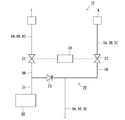
この場合、図11(A)に示すように、上流側給水路9A、9B、9Cに開閉弁40を介して蓄圧器30を連通するとよい。この便器洗浄装置100では、鉢洗浄工程の際にリム用開閉弁22を開閉するタイミング及びジェット洗浄工程の際にジェット用開閉弁21を開閉するタイミングに合わせて、開閉弁40を開閉する。これにより、リム吐水口4A及びジェット吐水口7Aから吐水する洗浄水の流量を設定値以上にしつつ、リム吐水口4Aからの洗浄水の吐水とジェット吐水口7Aからの洗浄水の吐水とを連続して行うことができる。
また、図11(B)に示すように、上流側給水路9A、9B、9Cに流路切替弁50と管径が相違する給排水管50A、50Bを介して蓄圧器30を連通するとよい。この便器洗浄装置110では、流路切替弁50を切り替えることにより、鉢洗浄工程の際に管径が小さい方の給排水管50Aから蓄圧器30に蓄圧状態で貯留された洗浄水が流出する。一方、ジェット洗浄工程の際に管径が大きい方の給排水管50Bから蓄圧器30に蓄圧状態で貯留された洗浄水が流出する。これにより、ジェット洗浄工程の際にジェット吐水口7Aから吐水する洗浄水の当初の流量を鉢洗浄工程の際にリム吐水口4Aから吐水する洗浄水の流量よりも多くすることができる。
また、図11(C)に示すように、ジェット側流路8Bに流路切替弁51を介して蓄圧器30を連通するとよい。この便器洗浄装置120では、鉢洗浄工程の際にリム用開閉弁22を開閉するタイミング及びジェット洗浄工程の際にジェット用開閉弁21を開閉するタイミングに合わせて、流路切替弁51を切り替えて、蓄圧器30に蓄圧状態で貯留された洗浄水をリム吐水口4A又はジェット吐水口7Aから吐水する洗浄水に付加する。これにより、リム吐水口4A及びジェット吐水口7Aから吐水する洗浄水の流量を設定値以上にしつつ、リム吐水口4Aからの洗浄水の吐水とジェット吐水口7Aからの洗浄水の吐水とを連続して行うことができる。
(2)実施例では、流量増幅機構として蓄圧器30を採用していたが、流量増幅機構はタンクとポンプとから構成してもよい。
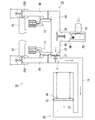
この場合、図12(A)に示すように、タンク35及びポンプ36をジェット側給水路8A、8B、8Cの上流側から順に直列的に設けるとよい。この便器洗浄装置200は、上流側給水路9A、9B、9Cに開閉弁41、上流側給水路9A、9B、9Cがリム側給水路5A、5B、5Cとジェット側給水路8A、8B、8Cとに分岐する部分に流路切替弁52を設けている。また、この便器洗浄装置200は、ポンプ36の下流側のジェット側給水路8A、8B、8Cとリム側給水路5A、5B、5Cと連通するパイパス流路70を設けている。バイパス流路70は開閉弁42と逆止弁60とを設けている。逆止弁60は、ジェット側給水路8A、8B、8Cからリム側給水路5A、5B、5Cへ洗浄水が流れることを許容し、その逆の流れを阻止する。
この便器洗浄装置200では、鉢洗浄工程において、リム吐水口4Aから洗浄水を吐水する際、流路切替弁52を切り替えて、給水源から供給される洗浄水をリム吐水口4Aに供給するとともに、開閉弁42を開弁し、かつポンプ36を駆動してタンク35に貯留された一部の洗浄水をバイパス流路70を介してリム吐水口4Aに供給する。また、ジェット洗浄工程において、ジェット吐水口7Aから洗浄水を吐水する際、開閉弁42を閉弁し、かつポンプ36を駆動してタンク35に貯留された残部の洗浄水をジェット吐水口7Aに供給する。この際、ポンプ36はリム吐水口4A及びジェット吐水口7Aから吐水する洗浄水の流量を設定値以上になるように駆動する。
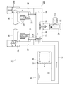
また、図12(B)に示すように、上流側から順にタンク35及びポンプ36の順に配置された増幅流路37をジェット側給水路8A、8B、8Cに並列的に設けるとよい。この便器洗浄装置210も、上流側給水路9A、9B、9Cに開閉弁41、上流側給水路9A、9B、9Cがリム側給水路5A、5B、5Cとジェット側給水路8A、8B、8Cとに分岐する部分に流路切替弁52を設けている。また、この便器洗浄装置210は、増幅流路37の下流端がジェット側給水路8A、8B、8Cに合流する部分よりも下流側のジェット側給水路8A、8B、8Cとリム側給水路5A、5B、5Cと連通するパイパス流路70を設けている。バイパス流路70は開閉弁42と逆止弁60とを設けている。逆止弁60は、ジェット側給水路8A、8B、8Cからリム側給水路5A、5B、5Cへ洗浄水が流れることを許容し、その逆の流れを阻止する。
この便器洗浄装置210では、鉢洗浄工程において、リム吐水口4Aから洗浄水を吐水する際、流路切替弁52を切り替えて、給水源から供給される洗浄水をリム吐水口4Aに供給するとともに、開閉弁42を開弁し、かつポンプ36を駆動してタンク35に貯留された一部の洗浄水をバイパス流路70を介してリム吐水口4Aに供給する。また、ジェット洗浄工程において、ジェット吐水口7Aから洗浄水を吐水する際、流路切替弁52を切り替えて、給水源から供給される洗浄水をジェット吐水口7Aに供給するとともに、開閉弁42を閉弁し、かつポンプ36を駆動してタンク35に貯留された残部の洗浄水をジェット吐水口7Aに供給する。この際、ポンプ36はリム吐水口4A及びジェット吐水口7Aから吐水する洗浄水の流量を設定値以上になるように駆動する。
本発明は水洗式便器に利用可能である。
1…便器本体
2…便鉢部
3…リム通水路
4A…リム吐水口
6…便器排水路
7A…ジェット吐水口
5A、5B、5C…リム側給水路(5A…リム側給水管、5B…リム側流路、5C…リム側連結部)
8A、8B、8C…ジェット側給水路(8A…ジェット側給水管、8B…ジェット側流路、8C…ジェット側連結部)
9A、9B、9C…上流側給水路(9A…給水管、9B…上流側流路、9C…上流側連結部)
5A、5B、5C、8A、8B、8C、9A、9B、9C…給水路
10、100、110、120、200、210…便器洗浄装置
20…弁ユニット(給水切替機構)
21…ジェット用開閉弁
22…リム用開閉弁
23…流量調整弁
24…制御装置
30…蓄圧器(流量増幅機構)
33…タンク
35、36…流量増幅機構(35…タンク、36…ポンプ)
2…便鉢部
3…リム通水路
4A…リム吐水口
6…便器排水路
7A…ジェット吐水口
5A、5B、5C…リム側給水路(5A…リム側給水管、5B…リム側流路、5C…リム側連結部)
8A、8B、8C…ジェット側給水路(8A…ジェット側給水管、8B…ジェット側流路、8C…ジェット側連結部)
9A、9B、9C…上流側給水路(9A…給水管、9B…上流側流路、9C…上流側連結部)
5A、5B、5C、8A、8B、8C、9A、9B、9C…給水路
10、100、110、120、200、210…便器洗浄装置
20…弁ユニット(給水切替機構)
21…ジェット用開閉弁
22…リム用開閉弁
23…流量調整弁
24…制御装置
30…蓄圧器(流量増幅機構)
33…タンク
35、36…流量増幅機構(35…タンク、36…ポンプ)
Claims (5)
- 便鉢部、この便鉢部の上端開口部の内周縁に設けられたリム通水路、このリム通水路に沿って洗浄水を吐水するリム吐水口、前記便鉢部の下流側に連続して設けられた便器排水路、及びこの便器排水路の下流側に向けて洗浄水を吐水するジェット吐水口を有する便器本体に洗浄水を供給する便器洗浄装置であって、
前記リム吐水口及び前記ジェット吐水口へ洗浄水を供給する給水路と、
この給水路に設けられ、前記リム吐水口及び前記ジェット吐水口から洗浄水を吐水して便器洗浄を行う際、先ず前記リム吐水口から洗浄水を吐水し、その後に連続して前記ジェット吐水口から洗浄水を吐水するように給水先を切り替える給水切替機構と、
前記給水路に連通して洗浄水を貯留するタンクを有し、前記リム吐水口及び前記ジェット吐水口から吐水する洗浄水の流量が設定値以上になるように、前記タンク内に貯留した洗浄水の一部を前記リム吐水口から吐水し、残部を前記ジェット吐水口から吐水する流量増幅機構とを備えていることを特徴とする便器洗浄装置。 - 前記ジェット吐水口から吐水する洗浄水の当初の流量は、前記リム吐水口から吐水する洗浄水の流量よりも多いことを特徴とする請求項1記載の便器洗浄装置。
- 前記リム吐水口から吐水する前記タンク内に貯留した一部の洗浄水の水量よりも前記ジェット吐水口から吐水する前記タンク内に貯留した残部の洗浄水の水量を多くして、前記ジェット吐水口から吐水する洗浄水の水量が前記リム吐水口から吐水する洗浄水の水量よりも多いことを特徴とする請求項1又は2記載の便器洗浄装置。
- 前記給水路は、給水源に連通する上流側給水路と、この上流側給水路の下流端を分岐して形成したジェット側給水路及びリム側給水路とから構成されており、
前記流量増幅機構はジェット側給水路に連通していることを特徴とする請求項1又は2記載の便器洗浄装置。 - 前記給水切替機構は、前記ジェット側給水路を開閉するジェット用開閉弁と、前記リム側給水路を開閉するリム用開閉弁と、前記ジェット用開閉弁及び前記リム用開閉弁の開閉を制御する制御装置とを有しており、
前記ジェット用開閉弁よりも上流側の前記ジェット側給水路に前記流量増幅機構を連通し、この流量増幅機構を連通した連通部よりも上流側の前記ジェット側給水路に設けられ、前記ジェット側給水路の下流側への大流量の流れを許容し、上流側への小流量の流れを許容する流量調整弁を備えていることを特徴とする請求項4記載の便器洗浄装置。
Priority Applications (1)
| Application Number | Priority Date | Filing Date | Title |
|---|---|---|---|
| CN201180027188.3A CN102918215B (zh) | 2010-08-06 | 2011-07-29 | 便器冲洗装置 |
Applications Claiming Priority (2)
| Application Number | Priority Date | Filing Date | Title |
|---|---|---|---|
| JP2010-176903 | 2010-08-06 | ||
| JP2010176903A JP5700483B2 (ja) | 2010-08-06 | 2010-08-06 | 便器洗浄装置 |
Publications (1)
| Publication Number | Publication Date |
|---|---|
| WO2012017940A1 true WO2012017940A1 (ja) | 2012-02-09 |
Family
ID=45559441
Family Applications (1)
| Application Number | Title | Priority Date | Filing Date |
|---|---|---|---|
| PCT/JP2011/067429 Ceased WO2012017940A1 (ja) | 2010-08-06 | 2011-07-29 | 便器洗浄装置 |
Country Status (4)
| Country | Link |
|---|---|
| JP (1) | JP5700483B2 (ja) |
| CN (1) | CN102918215B (ja) |
| TW (1) | TWI542764B (ja) |
| WO (1) | WO2012017940A1 (ja) |
Families Citing this family (9)
| Publication number | Priority date | Publication date | Assignee | Title |
|---|---|---|---|---|
| JP5936226B2 (ja) * | 2012-03-09 | 2016-06-22 | 株式会社Lixil | 便器洗浄装置 |
| JP6854084B2 (ja) * | 2016-02-29 | 2021-04-07 | 株式会社Lixil | 蓄圧装置 |
| JP6831060B2 (ja) * | 2016-05-31 | 2021-02-17 | 株式会社Lixil | 便器装置 |
| JP7129005B2 (ja) * | 2018-09-28 | 2022-09-01 | Toto株式会社 | 水洗大便器 |
| US11111658B2 (en) * | 2018-09-28 | 2021-09-07 | Toto Ltd. | Flush toilet |
| EP4148197A1 (en) | 2019-10-10 | 2023-03-15 | SDB IP Holdings, LLC | Toilet fixture clog prevention and cleanout |
| KR102331094B1 (ko) * | 2020-09-28 | 2021-12-01 | 김창호 | 위생도기용 급수장치 |
| JP7213855B2 (ja) * | 2020-09-29 | 2023-01-27 | 株式会社Lixil | 便器装置 |
| KR20260049569A (ko) * | 2023-08-10 | 2026-04-14 | 가부시키가이샤 리쿠시루 | 변기 장치 |
Citations (6)
| Publication number | Priority date | Publication date | Assignee | Title |
|---|---|---|---|---|
| JPH02256730A (ja) * | 1989-03-30 | 1990-10-17 | Toto Ltd | 大便器の洗浄給水装置 |
| JP2003213773A (ja) * | 2002-01-24 | 2003-07-30 | Toto Ltd | 便器装置 |
| JP2005120742A (ja) * | 2003-10-17 | 2005-05-12 | Inax Corp | 蓄圧装置及び便器洗浄装置 |
| JP2007247282A (ja) * | 2006-03-16 | 2007-09-27 | Inax Corp | 便器洗浄装置 |
| JP2008156937A (ja) * | 2006-12-25 | 2008-07-10 | Inax Corp | 便器洗浄装置 |
| JP2009256888A (ja) * | 2008-04-14 | 2009-11-05 | Inax Corp | 蓄圧装置及び便器洗浄装置 |
Family Cites Families (4)
| Publication number | Priority date | Publication date | Assignee | Title |
|---|---|---|---|---|
| JP4110853B2 (ja) * | 2002-06-21 | 2008-07-02 | Toto株式会社 | 便器装置 |
| CN2777077Y (zh) * | 2004-12-15 | 2006-05-03 | 郑守东 | 一种带蓄能储水器的马桶供水装置 |
| JP5361250B2 (ja) * | 2008-05-29 | 2013-12-04 | 株式会社Lixil | 洋風水洗式便器 |
| CN201502099U (zh) * | 2009-09-25 | 2010-06-09 | 刘庆利 | 充气式节水马桶 |
-
2010
- 2010-08-06 JP JP2010176903A patent/JP5700483B2/ja not_active Expired - Fee Related
-
2011
- 2011-07-29 CN CN201180027188.3A patent/CN102918215B/zh not_active Expired - Fee Related
- 2011-07-29 WO PCT/JP2011/067429 patent/WO2012017940A1/ja not_active Ceased
- 2011-08-05 TW TW100127901A patent/TWI542764B/zh not_active IP Right Cessation
Patent Citations (6)
| Publication number | Priority date | Publication date | Assignee | Title |
|---|---|---|---|---|
| JPH02256730A (ja) * | 1989-03-30 | 1990-10-17 | Toto Ltd | 大便器の洗浄給水装置 |
| JP2003213773A (ja) * | 2002-01-24 | 2003-07-30 | Toto Ltd | 便器装置 |
| JP2005120742A (ja) * | 2003-10-17 | 2005-05-12 | Inax Corp | 蓄圧装置及び便器洗浄装置 |
| JP2007247282A (ja) * | 2006-03-16 | 2007-09-27 | Inax Corp | 便器洗浄装置 |
| JP2008156937A (ja) * | 2006-12-25 | 2008-07-10 | Inax Corp | 便器洗浄装置 |
| JP2009256888A (ja) * | 2008-04-14 | 2009-11-05 | Inax Corp | 蓄圧装置及び便器洗浄装置 |
Also Published As
| Publication number | Publication date |
|---|---|
| JP5700483B2 (ja) | 2015-04-15 |
| CN102918215B (zh) | 2015-05-20 |
| CN102918215A (zh) | 2013-02-06 |
| TWI542764B (zh) | 2016-07-21 |
| JP2012036622A (ja) | 2012-02-23 |
| TW201215747A (en) | 2012-04-16 |
Similar Documents
| Publication | Publication Date | Title |
|---|---|---|
| JP5700483B2 (ja) | 便器洗浄装置 | |
| JP6766119B2 (ja) | サイフォン式水洗トイレ便器において使用するための水洗弁 | |
| HK1205543A1 (en) | Flush toilet | |
| JP5569853B2 (ja) | 水洗便器のタンク構造 | |
| US20130291297A1 (en) | Toilet flushing device and flush toilet | |
| JP2005264469A (ja) | 水洗便器 | |
| JP4793019B2 (ja) | 便器洗浄装置及び洗浄方法 | |
| JP6168646B2 (ja) | 便器洗浄装置 | |
| US20080120770A1 (en) | Water-conserving toilet using timer-controlled valve | |
| JP2007146655A (ja) | 水洗便器 | |
| JP5299832B2 (ja) | 水洗大便器 | |
| JP6029725B2 (ja) | 便器洗浄装置 | |
| JP5815242B2 (ja) | 便器洗浄装置 | |
| JP4305359B2 (ja) | 便器装置 | |
| JP2002327479A (ja) | 水洗便器 | |
| JP2005120742A (ja) | 蓄圧装置及び便器洗浄装置 | |
| WO2013145999A1 (ja) | 便器洗浄装置 | |
| JP2013147828A (ja) | 便器洗浄装置及び水洗式便器 | |
| JP2019065492A (ja) | 水道直圧式水洗大便器 | |
| JP4793614B2 (ja) | 床上排水サイフォン式水洗便器 | |
| JP4281519B2 (ja) | 便器洗浄装置 | |
| JP2007255069A (ja) | 便器設備及び便器洗浄方法 | |
| JP2002364056A (ja) | 水洗式便器 | |
| JP6432142B2 (ja) | 水洗大便器 | |
| JP2011214277A (ja) | 水洗大便器 |
Legal Events
| Date | Code | Title | Description |
|---|---|---|---|
| WWE | Wipo information: entry into national phase |
Ref document number: 201180027188.3 Country of ref document: CN |
|
| 121 | Ep: the epo has been informed by wipo that ep was designated in this application |
Ref document number: 11814566 Country of ref document: EP Kind code of ref document: A1 |
|
| NENP | Non-entry into the national phase |
Ref country code: DE |
|
| 122 | Ep: pct application non-entry in european phase |
Ref document number: 11814566 Country of ref document: EP Kind code of ref document: A1 |