WO2012017917A1 - ダンパ装置 - Google Patents
ダンパ装置 Download PDFInfo
- Publication number
- WO2012017917A1 WO2012017917A1 PCT/JP2011/067280 JP2011067280W WO2012017917A1 WO 2012017917 A1 WO2012017917 A1 WO 2012017917A1 JP 2011067280 W JP2011067280 W JP 2011067280W WO 2012017917 A1 WO2012017917 A1 WO 2012017917A1
- Authority
- WO
- WIPO (PCT)
- Prior art keywords
- spline
- shaft
- inner spline
- plate
- inner peripheral
- Prior art date
Links
Images


Classifications
-
- F—MECHANICAL ENGINEERING; LIGHTING; HEATING; WEAPONS; BLASTING
- F16—ENGINEERING ELEMENTS AND UNITS; GENERAL MEASURES FOR PRODUCING AND MAINTAINING EFFECTIVE FUNCTIONING OF MACHINES OR INSTALLATIONS; THERMAL INSULATION IN GENERAL
- F16F—SPRINGS; SHOCK-ABSORBERS; MEANS FOR DAMPING VIBRATION
- F16F15/00—Suppression of vibrations in systems; Means or arrangements for avoiding or reducing out-of-balance forces, e.g. due to motion
- F16F15/10—Suppression of vibrations in rotating systems by making use of members moving with the system
- F16F15/12—Suppression of vibrations in rotating systems by making use of members moving with the system using elastic members or friction-damping members, e.g. between a rotating shaft and a gyratory mass mounted thereon
- F16F15/131—Suppression of vibrations in rotating systems by making use of members moving with the system using elastic members or friction-damping members, e.g. between a rotating shaft and a gyratory mass mounted thereon the rotating system comprising two or more gyratory masses
- F16F15/139—Suppression of vibrations in rotating systems by making use of members moving with the system using elastic members or friction-damping members, e.g. between a rotating shaft and a gyratory mass mounted thereon the rotating system comprising two or more gyratory masses characterised by friction-damping means
- F16F15/1395—Suppression of vibrations in rotating systems by making use of members moving with the system using elastic members or friction-damping members, e.g. between a rotating shaft and a gyratory mass mounted thereon the rotating system comprising two or more gyratory masses characterised by friction-damping means characterised by main friction means acting radially outside the circumferential lines of action of the elastic members
-
- F—MECHANICAL ENGINEERING; LIGHTING; HEATING; WEAPONS; BLASTING
- F16—ENGINEERING ELEMENTS AND UNITS; GENERAL MEASURES FOR PRODUCING AND MAINTAINING EFFECTIVE FUNCTIONING OF MACHINES OR INSTALLATIONS; THERMAL INSULATION IN GENERAL
- F16F—SPRINGS; SHOCK-ABSORBERS; MEANS FOR DAMPING VIBRATION
- F16F15/00—Suppression of vibrations in systems; Means or arrangements for avoiding or reducing out-of-balance forces, e.g. due to motion
- F16F15/30—Flywheels
- F16F15/315—Flywheels characterised by their supporting arrangement, e.g. mountings, cages, securing inertia member to shaft
- F16F15/3153—Securing inertia members to the shafts
-
- B—PERFORMING OPERATIONS; TRANSPORTING
- B60—VEHICLES IN GENERAL
- B60K—ARRANGEMENT OR MOUNTING OF PROPULSION UNITS OR OF TRANSMISSIONS IN VEHICLES; ARRANGEMENT OR MOUNTING OF PLURAL DIVERSE PRIME-MOVERS IN VEHICLES; AUXILIARY DRIVES FOR VEHICLES; INSTRUMENTATION OR DASHBOARDS FOR VEHICLES; ARRANGEMENTS IN CONNECTION WITH COOLING, AIR INTAKE, GAS EXHAUST OR FUEL SUPPLY OF PROPULSION UNITS IN VEHICLES
- B60K6/00—Arrangement or mounting of plural diverse prime-movers for mutual or common propulsion, e.g. hybrid propulsion systems comprising electric motors and internal combustion engines ; Control systems therefor, i.e. systems controlling two or more prime movers, or controlling one of these prime movers and any of the transmission, drive or drive units Informative references: mechanical gearings with secondary electric drive F16H3/72; arrangements for handling mechanical energy structurally associated with the dynamo-electric machine H02K7/00; machines comprising structurally interrelated motor and generator parts H02K51/00; dynamo-electric machines not otherwise provided for in H02K see H02K99/00
- B60K6/20—Arrangement or mounting of plural diverse prime-movers for mutual or common propulsion, e.g. hybrid propulsion systems comprising electric motors and internal combustion engines ; Control systems therefor, i.e. systems controlling two or more prime movers, or controlling one of these prime movers and any of the transmission, drive or drive units Informative references: mechanical gearings with secondary electric drive F16H3/72; arrangements for handling mechanical energy structurally associated with the dynamo-electric machine H02K7/00; machines comprising structurally interrelated motor and generator parts H02K51/00; dynamo-electric machines not otherwise provided for in H02K see H02K99/00 the prime-movers consisting of electric motors and internal combustion engines, e.g. HEVs
- B60K6/42—Arrangement or mounting of plural diverse prime-movers for mutual or common propulsion, e.g. hybrid propulsion systems comprising electric motors and internal combustion engines ; Control systems therefor, i.e. systems controlling two or more prime movers, or controlling one of these prime movers and any of the transmission, drive or drive units Informative references: mechanical gearings with secondary electric drive F16H3/72; arrangements for handling mechanical energy structurally associated with the dynamo-electric machine H02K7/00; machines comprising structurally interrelated motor and generator parts H02K51/00; dynamo-electric machines not otherwise provided for in H02K see H02K99/00 the prime-movers consisting of electric motors and internal combustion engines, e.g. HEVs characterised by the architecture of the hybrid electric vehicle
- B60K6/44—Series-parallel type
- B60K6/445—Differential gearing distribution type
-
- B—PERFORMING OPERATIONS; TRANSPORTING
- B60—VEHICLES IN GENERAL
- B60Y—INDEXING SCHEME RELATING TO ASPECTS CROSS-CUTTING VEHICLE TECHNOLOGY
- B60Y2400/00—Special features of vehicle units
- B60Y2400/48—Vibration dampers, e.g. dual mass flywheels
-
- F—MECHANICAL ENGINEERING; LIGHTING; HEATING; WEAPONS; BLASTING
- F16—ENGINEERING ELEMENTS AND UNITS; GENERAL MEASURES FOR PRODUCING AND MAINTAINING EFFECTIVE FUNCTIONING OF MACHINES OR INSTALLATIONS; THERMAL INSULATION IN GENERAL
- F16D—COUPLINGS FOR TRANSMITTING ROTATION; CLUTCHES; BRAKES
- F16D1/00—Couplings for rigidly connecting two coaxial shafts or other movable machine elements
- F16D1/10—Quick-acting couplings in which the parts are connected by simply bringing them together axially
- F16D2001/103—Quick-acting couplings in which the parts are connected by simply bringing them together axially the torque is transmitted via splined connections
-
- F—MECHANICAL ENGINEERING; LIGHTING; HEATING; WEAPONS; BLASTING
- F16—ENGINEERING ELEMENTS AND UNITS; GENERAL MEASURES FOR PRODUCING AND MAINTAINING EFFECTIVE FUNCTIONING OF MACHINES OR INSTALLATIONS; THERMAL INSULATION IN GENERAL
- F16D—COUPLINGS FOR TRANSMITTING ROTATION; CLUTCHES; BRAKES
- F16D3/00—Yielding couplings, i.e. with means permitting movement between the connected parts during the drive
- F16D3/02—Yielding couplings, i.e. with means permitting movement between the connected parts during the drive adapted to specific functions
- F16D3/14—Yielding couplings, i.e. with means permitting movement between the connected parts during the drive adapted to specific functions combined with a friction coupling for damping vibration or absorbing shock
-
- Y—GENERAL TAGGING OF NEW TECHNOLOGICAL DEVELOPMENTS; GENERAL TAGGING OF CROSS-SECTIONAL TECHNOLOGIES SPANNING OVER SEVERAL SECTIONS OF THE IPC; TECHNICAL SUBJECTS COVERED BY FORMER USPC CROSS-REFERENCE ART COLLECTIONS [XRACs] AND DIGESTS
- Y02—TECHNOLOGIES OR APPLICATIONS FOR MITIGATION OR ADAPTATION AGAINST CLIMATE CHANGE
- Y02T—CLIMATE CHANGE MITIGATION TECHNOLOGIES RELATED TO TRANSPORTATION
- Y02T10/00—Road transport of goods or passengers
- Y02T10/60—Other road transportation technologies with climate change mitigation effect
- Y02T10/62—Hybrid vehicles
-
- Y—GENERAL TAGGING OF NEW TECHNOLOGICAL DEVELOPMENTS; GENERAL TAGGING OF CROSS-SECTIONAL TECHNOLOGIES SPANNING OVER SEVERAL SECTIONS OF THE IPC; TECHNICAL SUBJECTS COVERED BY FORMER USPC CROSS-REFERENCE ART COLLECTIONS [XRACs] AND DIGESTS
- Y10—TECHNICAL SUBJECTS COVERED BY FORMER USPC
- Y10T—TECHNICAL SUBJECTS COVERED BY FORMER US CLASSIFICATION
- Y10T74/00—Machine element or mechanism
- Y10T74/21—Elements
- Y10T74/2121—Flywheel, motion smoothing-type
Definitions
- the present invention is based on the priority claim of Japanese Patent Application: Japanese Patent Application No. 2010-177924 (filed on Aug. 6, 2010), the entire contents of which are incorporated herein by reference. Shall.
- the present invention relates to a damper device that absorbs fluctuating torque between two shafts, and more particularly, to a damper device that connects inertia bodies.
- the damper device is disposed, for example, on a power transmission path between the engine and the transmission, and absorbs (suppresses) a fluctuation torque due to the engine and the transmission.
- the damper device has a damper part that absorbs fluctuating torque by spring force, a hysteresis part that absorbs (suppresses) fluctuating torque by hysteresis torque due to friction, etc., and when the torsion of the rotating shaft cannot be absorbed by the damper part or hysteresis part And a limiter portion that causes slippage.
- gear rattling noise is generated in the transmission due to engine vibration.
- a transmission input shaft is connected to an electric motor (may be a generator motor) via a planetary gear mechanism in a power transmission device mounted on a hybrid vehicle using an engine and an electric motor as power sources.
- an electric motor may be a generator motor
- the occurrence of gear rattling noise in the transmission due to engine vibration is significant.
- an inertial body is connected to a damper device on a power transmission path between an engine and a transmission.
- Patent Document 1 discloses a hybrid drive device damper that transmits while suppressing fluctuating torque generated by a first power source and a second power source, and is a first that is rotationally driven by the first power source.
- a limiter mechanism that interrupts transmission of power from the first rotating member to the second rotating member when a fluctuation torque between the first rotating member and the second rotating member reaches a predetermined value; and the first rotating member Or the thing provided with the inertial body formed in the 2nd rotation member is disclosed.
- FIG. 1 discloses a hybrid drive device damper that transmits while suppressing fluctuating torque generated by a first power source and a second power source, and is a first that is rotationally driven by the first power source.
- the second rotating member is connected to the carrier shaft of the planetary gear mechanism, and the inner periphery of the inertial body is spline-coupled to the carrier shaft, so that the relative rotation with respect to the carrier shaft is impossible. It can move in the direction.
- a rubber or resin elastic body is provided between the inertia body and the second rotating member and in the axial gap between the inertia body and the carrier shaft to close up the play in the axial direction of the inertia body.
- Patent Document 1 Note that the entire disclosure of Patent Document 1 is incorporated herein by reference. The following analysis is given by the present invention.
- the structure shown in FIG. 7 of Patent Document 1 is a structure in which the inertial body and the carrier shaft are spline-coupled, and play occurs at the spline-coupled portion. There is a possibility that vibration is generated due to the play, and rattling noise is generated at the spline coupling portion or the gear portion of the planetary gear mechanism.
- a first object of the present invention is to provide a damper device that can eliminate rattling at a spline coupling portion between an inertial body and a shaft.
- a second object of the present invention is to provide a damper device that can stably maintain the axial positioning function of the inertial body.
- a first shaft that outputs rotational power of a power source
- a second shaft that transmits rotational power to a gear mechanism and has an outer spline
- rotational power of the first shaft Is transmitted
- a second rotating member that is spline-engaged with the outer spline
- a damper that absorbs variable torque between the first rotating member and the second rotating member
- the outer An inertial body having an inner spline engaged with the spline and having a substantially annular shape, and a tooth portion of one of the outer spline and the inner spline in the circumferential direction of the inertial body. Is pressed against the tooth portion of the other spline of the outer spline and the inner spline.
- the inertial body is separated from the first inner spline by a predetermined distance with respect to the first inner spline engaged with the outer spline as the inner spline and the axial direction of the second shaft.
- the inertial body is separated from the first inner spline by a predetermined distance with respect to the first inner spline engaged with the outer spline as the inner spline and the axial direction of the second shaft.
- a second inner spline that is press-fitted into the outer spline at a position where the tooth portion of the second inner spline is pressed against the tooth portion of the outer spline in the circumferential direction of the inertial body. It is preferred that
- the inertial body extends from the annular portion toward the inner periphery, and has a first plate having the first inner spline at an inner peripheral end, and an inner periphery from the annular portion. And a second plate having the second inner spline at the inner peripheral end, and a rivet for connecting the first plate and the second plate.
- At least one of the first plate and the second plate is formed of a plate member and has a plurality of slits.
- the inertial body is constituted by one member, and has a first inner peripheral extending portion and a second inner peripheral extending portion extending from the inner peripheral end of the annular portion, It is preferable that the first inner peripheral extending portion has the first inner spline at an inner peripheral end portion, and the second inner peripheral extending portion has the second inner spline at an inner peripheral end portion.
- the inertia body has a slit extending in a radial direction between circumferential directions of the first inner peripheral extending portion and the second inner peripheral extending portion.
- At least one of the first inner peripheral extending portion and the second inner peripheral extending portion has a plurality of second slits extending in the radial direction. .
- the second inner spline is arranged closer to a tip end side of the second shaft than the first inner spline.
- the second shaft has a step side wall portion at an end on the back side of the outer spline, and one of the first inner spline and the second inner spline is the step side wall. It is preferable that the other of the first inner spline and the second inner spline is in pressure contact with the second rotating member.
- the second shaft has a stepped side wall portion at an end on the back side of the outer spline, and one of the first inner spline and the second inner spline, A metal elastic body that is disposed between the stepped side wall portion and urges the one inner spline toward the second rotating member, and includes the first inner spline and the second inner spline.
- the other inner spline is preferably in pressure contact with the second rotating member.
- the second shaft has a stepped side wall portion at an end on the back side of the outer spline, and one of the first inner spline and the second inner spline, A metal elastic body arranged between the second rotating member and urging the one inner spline toward the stepped side wall portion, and includes the first inner spline and the second inner spline.
- the other inner spline is preferably in pressure contact with the step side wall.
- the teeth of one spline of the outer spline of the second shaft and the inner spline of the inertial body are set so as to tighten the teeth of the other spline from both sides in the circumferential direction.
- rattling of the inertial body in the circumferential direction with respect to the second shaft is suppressed, and generation of rattling noise and the like in the gear mechanism can be suppressed.
- the inertial body is sandwiched between the stepped side wall portion of the second shaft and the second rotating member, the axial backlash of the inertial body with respect to the second shaft is prevented. It is suppressed and the inertial body can be positioned.
- rotational power is supplied to the first shaft (1a in FIGS. 1 and 2) that outputs the rotational power of the power source (1 in FIG. 1) and the gear mechanism (4 in FIG. 1).
- a second shaft (29 in FIGS. 1 and 2) having an outer spline (29a in FIG. 2) and a first rotating member (20 and 21 in FIG. 2) to which the rotational power of the first shaft is transmitted.
- a second rotating member (28 in FIG. 2) that is spline-engaged with the outer spline, and a damper portion (3a in FIG. 2) that absorbs variable torque between the first rotating member and the second rotating member. )
- an inertial body (30 in FIG.
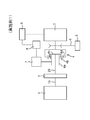
- FIG. 1 is a schematic diagram schematically illustrating a configuration of a hybrid drive device having a damper device according to a first embodiment of the present invention.
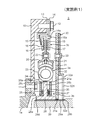
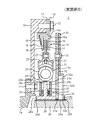
- FIG. 2 is a partial radial cross-sectional view schematically illustrating the configuration of the damper device according to the first embodiment of the invention.
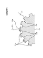
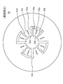
- FIG. 3 is a plan view seen from the axial direction schematically showing the configuration of the inertial body in the damper device according to Embodiment 1 of the present invention.
- FIG. 4 is a schematic diagram illustrating an engagement state between the inertial body and the shaft in the damper device according to the first embodiment of the present invention.
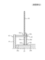
- FIG. 5 is a partial radial cross-sectional view showing a state in the middle of assembling the inertial body to the shaft in the damper device according to the first embodiment of the present invention.
- the hybrid drive device is disposed between an engine 1 as a first power source, an electric motor 2 as a second power source, and between the engine 1 and the electric motor 2.
- a damper device 3 that suppresses the fluctuation torque between them, a planetary gear mechanism 4 disposed between the electric motor 2 and the damper device 3, a speed reduction mechanism 5 that transmits power to drive wheels (not shown),
- the belt 6 that connects the ring gear 4 d of the planetary gear mechanism 4 and the speed reduction mechanism 5, the power generation motor 7 that is connected to the sun gear 4 a of the planetary gear mechanism 4, and the power generation motor 7 and the electric motor 2 via the inverter 8 are electrically connected.
- a battery 9 connected to.
- the shaft 1 a serving as the output shaft of the engine 1 is connected to the carrier 4 c of the planetary gear mechanism 4 via the damper device 3 and the shaft 29.
- a pinion gear 4b is rotatably held on the carrier 4c.
- the pinion gear 4b is arranged so that the outer periphery of the sun gear 4a can revolve, and meshes with the sun gear 4a and the ring gear 4d.
- the rotating shaft of the generator motor 7 is connected to the sun gear 4 a of the planetary gear mechanism 4, and is for charging the battery 9 with electric energy generated by driving the engine 1.
- the rotating shaft of the electric motor 2 is connected to the ring gear 4d.
- the rotational power of the engine 1 is transmitted to the carrier 4c of the planetary gear mechanism 4 via the damper device 3 and the shaft 29, and the entire carrier 4c is the shaft 1a of the engine 1.
- the ring gear 4d rotates, and power is transmitted to the speed reduction mechanism 5 via the belt 6 to drive drive wheels (not shown).
- the sun gear 4 a also rotates and is generated by the generator motor 7, and the battery 9 is charged.
- the ring gear 4 d rotates and power is transmitted to the speed reduction mechanism 5 via the belt 6.
- the carrier 4c itself rotates only without changing its position, the power of the electric motor 2 is not transmitted to the engine 1 side.
- the hybrid drive device can also drive both the engine 1 and the electric motor 2 to transmit power to the speed reduction mechanism 5.
- Such switching of the power source switching between driving and non-driving of the electric motor 2 is switched by an electronic control device (not shown) by various signals such as the vehicle speed and the accelerator opening.
- the damper device 3 in the hybrid drive device has a torsional buffering function, a damper portion 3 a that absorbs a varying torque between the shaft 1 a and the shaft 29 by a spring force (elastic force), friction, and the like.
- the hysteresis portion 3b that absorbs (suppresses) the fluctuation torque between the shaft 1a and the shaft 29 by the hysteresis torque due to the above, and the fluctuation torque between the shaft 1a and the shaft 29 cannot be absorbed by the damper portion 3a or the hysteresis portion 3b.
- a limiter portion 3c that sometimes causes slipping.
- the damper portion 3a is disposed in parallel with the hysteresis portion 3b on the power transmission path.
- the limiter unit 3c is disposed in series with the damper unit 3a and the hysteresis unit 3b on the power transmission path.
- the damper device 3 is combined with the damper portion 3a and the hysteresis portion 3b in consideration of assembling properties to form an integral unit (assembly).
- the damper device 3 includes, as main components, a flywheel 10, bolts 11 and 12, a support plate 13, a cover plate 14, a disc spring 15, a pressure plate 16, a lining plate 17, and a friction material 18. , 19, side plates 20, 21, rivets 22, coil springs 23, sheet members 24, thrust members 25 and 26, disc springs 27, hub members 28, shafts 29, and inertial bodies 30. Have.
- the flywheel 10 is an annular plate member fastened to the shaft 1a of the engine (1 in FIG. 1) with bolts 11.
- the flywheel 10 has a cylindrical portion that protrudes toward the planetary gear mechanism (4 in FIG. 1) side (right side in FIG. 2) at the outer peripheral portion, and the support plate 13 and the cover plate 14 are bolts in the cylindrical portion. 12 is fastened and fixed.
- the flywheel 10 rotates integrally with the shaft 1a, the support plate 13, and the cover plate 14.
- the bolt 11 is a member for fastening and fixing the flywheel 10 to the shaft 1a of the engine (1 in FIG. 1).
- the bolt 12 is a member for fastening and fixing the support plate 13 and the cover plate 14 to the flywheel 10.
- the support plate 13 is an annular plate member disposed between the flywheel 10 and the cover plate 14, and is a constituent member of the limiter portion 3c.
- the support plate 13 is fastened to the flywheel 10 by bolts 12 together with the cover plate 14 at the outer peripheral portion.
- the support plate 13 is separated from the cover plate 14 at the inner peripheral portion, and supports the outer peripheral end of the disc spring 15.
- the cover plate 14 is an annular member disposed on the planetary gear mechanism (4 in FIG. 1) side (right side in FIG. 2) of the support plate 13, and is a constituent member of the limiter portion 3c.
- the cover plate 14 is fastened and fixed to the flywheel 10 by bolts 12 together with the support plate 13 at the outer peripheral portion.
- the cover plate 14 is separated from the support plate 13 at the inner peripheral portion.
- the cover plate 14 has a hole portion 14a for engaging (stopping) the pressure plate 16 so as not to rotate and to move in the axial direction.
- the convex portion 16a of the pressure plate 16 is inserted into the hole portion 14a.
- the cover plate 14 is slidably pressed against the friction material 19 at the inner peripheral portion.
- the disc spring 15 is an annular disc-shaped spring disposed between the support plate 13 and the pressure plate 16, and is a constituent member of the limiter portion 3c.
- the disc spring 15 is supported by the support plate 13 at the outer peripheral end.
- the disc spring 15 is in contact with the pressure plate 16 at the inner peripheral end, and biases the pressure plate 16 toward the friction material 18 side.
- the pressure plate 16 is an annular member disposed between the disc spring 15 and the friction material 18 and is a constituent member of the limiter portion 3c.
- the pressure plate 16 has a convex portion 16a for engaging (stopping) the cover plate 14 so as not to rotate and to move in the axial direction.
- the convex portion 16 a is inserted into the hole portion 14 a of the cover plate 14.
- the pressure plate 16 is urged toward the friction material 18 by the disc spring 15 and is slidably pressed against the friction material 18.
- the lining plate 17 is an annular member disposed between the friction materials 18 and 19 between the cover plate 14 and the pressure plate 16, and is a constituent member of the limiter portion 3c.
- the lining plate 17 is sandwiched between the side plate 20 and the side plate 21 at the inner peripheral portion, and is fixed by caulking with the side plate 20 and the side plate 21 by a plurality of rivets 22.
- the friction material 18 and 19 is being fixed to the lining plate 17 by the rivet, the adhesive agent, etc. in the outer peripheral part.
- the lining plate 17 rotates integrally with the friction materials 18 and 19 and the side plates 20 and 21.
- the friction material 18 is a constituent member of the limiter portion 3 c and is disposed between the lining plate 17 and the pressure plate 16.
- the friction material 18 is fixed to the lining plate 17 by rivets, an adhesive or the like.
- the friction material 18 is slidably pressed against the pressure plate 16.
- a material containing rubber, resin, fiber (short fiber, long fiber), particles for adjusting the friction coefficient ⁇ , and the like can be used.
- the friction material 19 is a constituent member of the limiter portion 3 c and is disposed between the lining plate 17 and the cover plate 14.
- the friction material 19 is fixed to the lining plate 17 by rivets, an adhesive or the like.
- the friction material 19 is slidably pressed against the cover plate 14.
- a material containing rubber, resin, fiber (short fiber, long fiber), particles for adjusting the friction coefficient ⁇ , and the like can be used.
- the side plate 20 is an annular member disposed on the engine (1 in FIG. 1) side (left side in FIG. 2) of the flange portion 28b of the hub member 28, and is a constituent member of the damper portion 3a and the hysteresis portion 3b. .
- the side plate 20 is caulked and fixed integrally with the lining plate 17 and the side plate 21 by a plurality of rivets 22 in the vicinity of the outer peripheral end portion.
- the side plate 20 has a window portion 20a for accommodating the coil spring 23 and the sheet member 24 at the damper portion 3a at the intermediate portion, and a circumferential end surface of the window portion 20a can be brought into contact with and separated from the sheet member 24. Touching.
- the side plate 20 is prevented from rotating by the thrust member 25 at the inner peripheral end portion, and is rotatably supported by the hub member 28 (hub portion 28a) via the thrust member 25.
- the side plate 20 rotates integrally with the lining plate 17, the friction materials 18 and 19, and the side plate 21.
- the side plate 21 is an annular member disposed on the planetary gear mechanism (4 in FIG. 1) side (right side in FIG. 2) of the flange portion 28b of the hub member 28, and is a constituent member of the damper portion 3a and the hysteresis portion 3b. It is.
- the side plate 21 is caulked and fixed integrally with the lining plate 17 and the side plate 20 by a plurality of rivets 22 in the vicinity of the outer peripheral end portion.
- the side plate 21 has a window portion 21 a for accommodating the coil spring 23 and the sheet member 24 at the damper portion 3 a in the intermediate portion, and the circumferential end surface of the window portion 21 a is capable of coming into contact with and separating from the sheet member 24. Touching.
- the side plate 21 supports the disc spring 27 at the hysteresis portion 3b on the inner peripheral side from the damper portion 3a.
- the side plate 21 is prevented from rotating by the thrust member 26 at the inner peripheral end portion, and is rotatably supported by the hub member 28 (hub portion 28a) via the thrust member 26.
- the side plate 21 rotates integrally with the lining plate 17, the friction materials 18 and 19, and the side plate 20.
- the rivet 22 is a member for caulking and fixing the lining plate 17, the side plate 20, and the side plate 21 together.
- the coil spring 23 is a component part of the damper portion 3a, and is accommodated in the window portions 20a, 21a, and 28c formed on the side plates 20 and 21 and the hub member 28 (flange portion 28b), and seats disposed at both ends. It is in contact with the member 24.
- the coil spring 23 contracts when the side plates 20 and 21 and the hub member 28 rotate relative to each other, and absorbs a shock due to a rotational difference between the side plates 20 and 21 and the hub member 28.
- the coil spring 23 can be a straight shape or a straight spring that is bent and assembled, but an arc spring bent along the circumferential direction can be used in order to realize a wide twist.
- the sheet member 24 is a component part of the damper portion 3a, and is accommodated in the side plates 20, 21 and the window portions 20a, 21a, 28c formed in the hub member 28 (flange portion 28b).
- the sheet member 24 is disposed at both ends in the contraction direction of the coil spring 23, and is disposed between the circumferential end surfaces of the window portions 20 a, 21 a, and 28 c and the end portion of the coil spring 23. Resin can be used for the sheet member 24 in order to reduce wear of the coil spring 23.
- the thrust member 25 is a component part of the hysteresis portion 3 b and is an annular member disposed between the side plate 20 and the hub member 28.
- the thrust member 25 is disposed between the side plate 20 and the flange portion 28b in the axial direction, and is slidably pressed against the flange portion 28b.
- the thrust member 25 is secured to the side plate 20 so as to be axially movable with respect to the side plate 20.
- the thrust member 25 is also interposed between the side plate 20 and the hub portion 28a in the radial direction, and serves as a sliding bearing (bush) for rotatably supporting the side plate 20 on the hub portion 28a.
- the thrust member 26 is a component part of the hysteresis part 3 b and is an annular member disposed between the side plate 21 and the hub member 28.
- the thrust member 26 is disposed between the disc spring 27 and the flange portion 28b in the axial direction.
- the thrust member 26 is urged toward the flange portion 28b by the disc spring 27 and is slidably pressed against the flange portion 28b. .
- the thrust member 26 is secured to the side plate 21 so as to be axially movable with respect to the side plate 21.
- the thrust member 26 is also interposed between the side plate 21 and the hub portion 28a in the radial direction, and serves as a sliding bearing (bush) for supporting the side plate 21 on the hub portion 28a so as to be relatively rotatable.
- the disc spring 27 is a component of the hysteresis portion 3b, and is a disc-shaped and annular spring that is disposed between the thrust member 26 and the side plate 21 and biases the thrust member 26 toward the flange portion 28b.
- the hub member 28 is a member that outputs rotational power from the damper portion 3a and the hysteresis portion 3b toward the shaft 29, and is a constituent member of the damper portion 3a and the hysteresis portion 3b.
- the hub member 28 has a flange portion 28b extending from a predetermined portion on the outer periphery of the hub portion 28a.
- the hub portion 28a has an inner spline 28d that is spline-engaged with the outer spline 29a of the shaft 29 on the inner peripheral surface.
- the hub portion 28 a supports the side plate 20 rotatably on the outer periphery via the thrust member 25, and supports the side plate 21 rotatably via the thrust member 26.
- the hub portion 28a regulates the axial movement of the plate 31 in the inertial body 30 at the end face on the planetary gear mechanism (4 in FIG. 1) side (right side in FIG. 2) in the axial direction.
- the flange part 28b has a window part 28c for accommodating the coil spring 23 and the sheet member 24 at the outer damper part 3a.
- the circumferential end surface of the window portion 28c is in contact with the sheet member 24 so as to be able to contact and separate.
- the flange portion 28b is slidably held by the thrust members 25 and 26 on the axial surface of the hysteresis portion 3b on the inner peripheral side of the damper portion 3a.
- the shaft 29 is a member for transmitting the rotational power from the engine (1 in FIG. 1) to the carrier (4c in FIG. 1) of the planetary gear mechanism (4 in FIG. 1) via the damper device (3 in FIG. 1). It is.
- the shaft 29 has an outer spline 29a formed on the outer peripheral surface in the vicinity of the end of the engine (1 in FIG. 1) side (left side in FIG. 2).
- a hub member 28 and an inertial body 30 are disposed on the outer periphery of the outer splan 29a.
- the outer spline 29a is in spline engagement with the inner spline 28d of the hub member 28.
- the outer spline 29 a is spline-engaged with the inner spline 31 a of the plate 31 and the inner spline 32 b of the plate 32 in the inertial body 30.
- the teeth of the outer splan 29a are tightened (sandwiched) by the inner spline 31a and the inner spline 32b from both sides in the circumferential direction (see FIG. 4).
- a stepped side wall portion 29b is provided at the end of the outer side plan 29a on the back side (right side in FIG. 2).
- the stepped side wall portion 29b is a side wall surface of the stepped portion whose diameter is increased at the end of the outer spur 29a.
- the step side wall portion 29b restricts the movement of the plate 32 in the inertial body 30 in the axial direction.
- the inertial body 30 has a substantially annular shape for suppressing the occurrence of rattling noise of the gear (4a, 4b, 4d in FIG. 1) in the planetary gear mechanism (4 in FIG. 1) due to vibration of the engine (1 in FIG. 1). It is a member.
- the inertia body 30 is attached to a shaft 29 connected to a carrier (4c in FIG. 1) in the planetary gear mechanism (4 in FIG. 1).
- the inertial body 30 has a function of suppressing rattling in the circumferential direction and the axial direction with respect to the shaft 29.
- the inertia body 30 is an assembly of the plate 31, the plate 32, and the rivet 33.
- the plate 31 is an annular flat plate member.
- the plate 31 is disposed closer to the side plate 21 than the plate 32.
- the plate 31 is in contact with the plate 32 at the outer peripheral portion, and is connected to the plate 32 by a plurality of rivets 33.
- the plate 31 is separated from the plate 32 (step inner peripheral extending portion 32a) at the inner peripheral portion.
- the plate 31 has an inner spline 31a formed at the inner peripheral end.
- the inner spline 31 a is in spline engagement with the outer spline 29 a of the shaft 29.
- the teeth of the inner spline 31a are set so as to be out of phase with the teeth of the inner spline 32b of the plate 32 when the inertial body 30 is not assembled to the shaft 29 (see FIG. 3).
- the outer spline 29a is set so as to be in pressure contact with the surface on one side in the circumferential direction of the teeth (see FIG. 4). That is, in a state where the inertial body 30 is assembled to the shaft 29, the teeth of the inner spline 31a and the teeth of the inner spline 32b are sandwiched from both sides in the circumferential direction of the teeth of the outer spline 29a. Thereby, the play of the circumferential direction with respect to the shaft 29 of the inertial body 30 is suppressed.
- the plate 31 has a correction hole 31b at a predetermined position away from the plate 32 (the step inner peripheral extending portion 32a).
- the correction hole 31b is used to insert the protrusion 42 of the correction jig 40 used to correct the phase shift of the teeth between the inner splines 31a and 32b when the inertial body 30 is assembled to the shaft 29.
- Through-holes see FIG. 5
- the correction hole 31b has a phase difference with the correction hole 32c of the plate 32 in accordance with the tooth phase shift between the inner splines 31a and 32b.
- a deviation is set (see FIG. 3).
- the plate 31 (including the inner spline 31a) is in pressure contact with the axial end surface of the hub portion 28a of the hub member 28.
- the plate 31 may be formed with a slit similar to the slit 32d in order to facilitate elastic deformation in the twisting direction (circumferential direction) and the axial direction.
- the plate 32 is an annular plate member having a step at an intermediate portion.
- the plate 32 can form a plate member by press molding.
- the plate 32 is arranged closer to the planetary gear mechanism (4 in FIG. 1) side (left side in FIG. 2) than the plate 31.
- the plate 32 is in contact with the plate 31 at the outer peripheral portion, and is connected to the plate 31 by a plurality of rivets 33.
- the plate 32 has a step at an intermediate portion and a step inner peripheral extending portion 32a separated from the plate 31 at an inner peripheral portion.
- the step inner peripheral extending portion 32a has an inner spline 32b formed at the inner peripheral end.
- the inner spline 32 b is in spline engagement with the outer spline 29 a of the shaft 29.
- the teeth of the inner spline 32b are set so as to be out of phase with the teeth of the inner spline 31a of the plate 31 when the inertial body 30 is not assembled to the shaft 29 (see FIG. 3).
- the outer spline 29a is set so as to be in pressure contact with the other surface in the circumferential direction of the teeth (see FIG. 4). That is, in a state where the inertial body 30 is assembled to the shaft 29, the teeth of the inner spline 32b and the teeth of the inner spline 31a are sandwiched from both sides in the circumferential direction of the teeth of the outer spline 29a.
- the step inner peripheral extension portion 32a has a correction hole portion 32c at a predetermined position.
- the correction hole 32c is used to insert the protrusion 42 of the correction jig 40 used to correct the tooth phase shift between the inner splines 31a and 32b when the inertial body 30 is assembled to the shaft 29.
- Through-holes see FIG. 5.
- the correction hole portion 32c has a phase difference with the correction hole portion 31b of the plate 31 according to the phase shift of the teeth between the inner splines 31a and 32b.
- a deviation is set (see FIG. 3).
- a plurality of slits 32 d for facilitating elastic deformation in the twisting direction (circumferential direction) and the axial direction are formed in the step inner circumferential extending portion 32 a.
- the step inner circumferential extension portion 32a is in pressure contact with the step side wall portion 29b so as to press the step side wall portion 29b of the shaft 29 at the inner spline 32b. That is, the inner spline 32b of the step inner peripheral extending portion 32a presses the step side wall portion 29b, so that the plate 31 (including the inner spline 31a) is pressed against the axial end surface of the hub portion 28a.
- the distance between the inner peripheral end of the step inner peripheral extending portion 32 a and the plate 31 is not that the inertial body 30 is assembled to the shaft 29 than the distance in the state where the inertial body 30 is assembled to the shaft 29.
- the state distance is set to be larger.
- the rivet 33 is a member for caulking and fixing the plate 31 and the plate 32 together.
- the correction hole 40 is inserted into the correction hole portion 31 b and the correction hole portion 32 c of the inertial body 30 in a single stage of the inertial body 30.
- the plate 31 and the plate 32 are relatively elastically deformed in the twisting direction (circumferential direction).
- the positions of the teeth of the inner splines 31a and 32b, which are relatively out of phase, coincide with each other when viewed from the axial direction, and the inertial body 30 is slid along the teeth of the outer spline 29a of the shaft 29 to the shaft 29 Can be installed.
- the correction jig 40 has a plurality of protrusions 42 on one surface of the pedestal portion 41.
- the pedestal 41 abuts against the tip of the shaft 29 and pushes out only the inertia body 30 when the inertia body 30 is attached to the shaft 29.
- the correction jig 40 is automatically removed. Thereby, an assembling property improves.
- the inertial body 30 is configured such that the phases of the inner splines 31a and 32b are shifted, so that the teeth of the inner spline 31a and the teeth of the inner spline 32b are in the circumferential direction of the teeth of the outer spline 29a. Since it is inserted from both sides, the rattling of the inertial body 30 with respect to the shaft 29 in the circumferential direction is suppressed, and the occurrence of rattling noise and the like in the gear mechanism can be suppressed.
- the inner spline 32b of the step inner peripheral extending portion 32a in the inertia body 30 presses the step side wall portion 29b of the shaft 29, and the inner spline 31a of the plate 31 is pressed against the axial end surface of the hub portion 28a, thereby inertia.
- the backlash in the axial direction of the body 30 with respect to the shaft 29 is suppressed, and the inertial body 30 can be positioned.
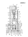
- FIG. 6 is a partial radial cross-sectional view schematically showing the configuration of the damper device according to the second embodiment of the present invention.
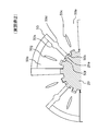
- FIG. 7 is the top view seen from the axial direction which showed typically the structure of the inertia body in the damper apparatus which concerns on Example 2 of this invention.
- FIG. 8 is a schematic diagram illustrating an engagement state between the inertial body and the shaft in the damper device according to the second embodiment of the present invention.
- FIG. 9 is a radial partial cross-sectional view illustrating a state in the middle of assembling the inertial body to the shaft in the damper device according to the second embodiment of the present invention.
- Example 2 is a modification of Example 1, and the inertial body 50 is configured by one member.
- the configuration other than the inertial body 50 is the same as that of the first embodiment.
- the inertial body 50 is an annular plate for suppressing generation of rattling noise of the gear (4a, 4b, 4d in FIG. 1) in the planetary gear mechanism (4 in FIG. 1) due to vibration of the engine (1 in FIG. 1). It is a member.
- the inertial body 50 is attached to a shaft 29 connected to a carrier (4c in FIG. 1) in the planetary gear mechanism (4 in FIG. 1).
- the inertial body 50 has a function of suppressing rattling in the circumferential direction and the axial direction with respect to the shaft 29.
- the inertial body 50 can be formed by pressing a single plate member.
- the inertia body 50 is disposed between the hub portion 28 a of the hub member 28 and the stepped side wall portion 29 b of the shaft 29.
- the inertial body 50 has a plurality of slits 50i formed from the inner peripheral end portion to the intermediate portion.
- the inertial body 50 includes a plurality of inner peripheral extending portions 50a extending from the inner peripheral end of the annular portion, and a plurality of step inner peripheral extending portions 50e.
- the inner peripheral extending part 50a is on the same plane as the annular part.
- the step inner circumferential extending portion 50e is formed with a step so as to be displaced in the axial direction from the annular portion.
- the slit 50i is a space formed between the inner peripheral extending part 50a and the step inner peripheral extending part 50e in the circumferential direction.
- the inner peripheral extending portions 50a and the step inner peripheral extending portions 50e are alternately arranged in the circumferential direction.
- the inner peripheral extension 50a has an inner spline 50b at the inner peripheral end.
- the inner spline 50 b is in spline engagement with the outer spline 29 a of the shaft 29.
- the step inner peripheral extending portion 50e has an inner spline 50f formed at the inner peripheral end.
- the inner spline 50f is in spline engagement with the outer spline 29a of the shaft 29.
- the teeth of the inner spline 50b are set so as to be out of phase with the teeth of the inner spline 50f when the inertial body 50 is not assembled to the shaft 29, and the inertial body 50 is assembled to the shaft 29.
- the outer spline 29a is set so as to be in pressure contact with one surface in the circumferential direction of the teeth (see FIG. 8). That is, in a state where the inertial body 50 is assembled to the shaft 29, the teeth of the inner spline 50b and the teeth of the inner spline 50f are inserted into the predetermined teeth of the outer spline 29a (the slits 50i having the recesses 50d and 50h). Insert the teeth from both sides in the circumferential direction. Thereby, the play of the inertial body 50 with respect to the shaft 29 in the circumferential direction is suppressed.
- the inner peripheral extending portion 50a has a correction concave portion 50d on one side wall surface in the circumferential direction.
- the step inner circumferential extending portion 50e has a correcting recess 50h on a circumferential wall surface facing the correcting recess 50d.
- the correction recesses 50d and 50h insert the protrusions 42 of the correction jig 40 that are used to correct the tooth phase shift between the inner splines 50b and 50f. (Refer to FIG. 9).
- the step inner peripheral extending portion 50e is set so that the correction concave portion 50h approaches the correction concave portion 50d when the inertial body 50 is not assembled to the shaft 29.
- a slit 50c for facilitating elastic deformation is formed in the inner peripheral extending portion 50a.
- a slit 50g for facilitating elastic deformation in the twist direction (circumferential direction) and the axial direction is formed in the inner circumferential extending portion 50e of the step.
- the inertia body 50 is in pressure contact with the axial end surface of the hub portion 28a of the hub member 28 at an inner peripheral extending portion 50a (including the inner spline 50b), and the shaft is formed at the inner spline 50f of the step inner peripheral extending portion 50e.
- the 29 stepped side wall portions 29b are pressed against the stepped side wall portions 29b so as to press. That is, the inner spline 50f of the step inner peripheral extension portion 50e presses the step side wall portion 29b, so that the inner peripheral extension portion 50a (including the inner spline 50b) is pressed against the axial end surface of the hub portion 28a.
- the axial distance between the inner peripheral end of the step inner peripheral extending portion 50e and the inner peripheral extending portion 50a is greater than the distance in the state where the inertia body 50 is assembled to the shaft 29. It is set so that the distance in a state where it is not assembled to is larger.
- the protrusion 42 of the correction jig 40 is inserted between the correction recesses 50d and 50f of the inertial body 50 at the stage of the inertial body 50 as a single unit.
- the circumferential extending portion 50a and the step inner circumferential extending portion 50e are relatively elastically deformed in the twisting direction (circumferential direction). Thereby, the positions of the teeth of the inner splines 50 b and 50 f that are relatively out of phase become normal positions, and the inertial body 50 can be slid along the teeth of the outer splines 29 a of the shaft 29 and attached to the shaft 29. it can.
- the correction jig 40 has a plurality of protrusions 42 on one surface of the pedestal portion 41.
- the pedestal 41 abuts against the tip of the shaft 29 and pushes out only the inertial body 50 when the inertial body 50 is mounted on the shaft 29.
- the correction jig 40 is automatically removed. Thereby, an assembling property improves.
- the same effects as those of the first embodiment can be obtained, and the inertial body 50 is formed by one member, so that the cost of the apparatus can be reduced.
- FIG. 10 is a partial radial cross-sectional view schematically showing the configuration of the damper device according to the third embodiment of the present invention.
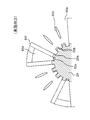
- FIG. 11 is the top view seen from the axial direction which showed typically the structure of the inertia body in the damper apparatus which concerns on Example 3 of this invention.
- FIG. 12 is a schematic diagram illustrating an engagement state between the inertial body and the shaft in the damper device according to the third embodiment of the present invention.
- the third embodiment is a modification of the first embodiment.
- the inner splines 60b and 60e are not shifted in phase, but the teeth of the inner splines 60e are press-fitted between the teeth of the outer splines 29a of the shaft 29.
- the teeth of the inner spline 60e are configured to be in pressure contact with the teeth of the outer spline 29a on both sides in the circumferential direction. In other words, the teeth of the inner spline 60e are fastened by the teeth of the outer spline 29a from both sides in the circumferential direction.
- the inertial body 60 is composed of a single member.
- the configuration other than the inertia body 60 is the same as that of the first embodiment.
- Inertial body 60 is an annular plate for suppressing the occurrence of rattling noise of gears (4a, 4b, 4d in FIG. 1) in planetary gear mechanism (4 in FIG. 1) due to vibration of engine (1 in FIG. 1). It is a member.
- the inertia body 60 is attached to the shaft 29 connected to the carrier (4c in FIG. 1) in the planetary gear mechanism (4 in FIG. 1).
- the inertia body 60 has a function of suppressing rattling in the circumferential direction and the axial direction with respect to the shaft 29.
- the inertial body 60 can be formed by pressing a single plate member.
- the inertia body 60 is disposed between the hub portion 28 a of the hub member 28 and the stepped side wall portion 29 b of the shaft 29.
- the inertial body 60 has a plurality of slits 60f formed from an inner peripheral end portion to an intermediate portion.
- the inertia body 60 has a plurality of inner peripheral extending portions 60a extending from the inner peripheral end of the annular portion, and a plurality of step inner peripheral extending portions 60d.
- the inner peripheral extending portion 60a is on the same plane as the annular portion.
- the step inner circumferential extending portion 60d is formed with a step so as to be displaced in the axial direction from the annular portion.
- the slit 60f is a space formed between the inner peripheral extending portion 60a and the step inner peripheral extending portion 60d in the circumferential direction.
- the inner peripheral extending portions 60a and the step inner peripheral extending portions 60d are alternately arranged in the circumferential direction.
- the circumferential width of the inner peripheral extending portion 60a is set larger than the circumferential width of the step inner peripheral extending portion 60d.
- the inner peripheral extension 60a has an inner spline 60b at the inner peripheral end.
- the inner spline 60 b is in spline engagement with the outer spline 29 a of the shaft 29.
- the step inner circumferential extending portion 60d has an inner spline 60e formed at the inner circumferential end.
- the inner spline 60e is press-fitted into the outer spline 29a of the shaft 29.
- the teeth of the inner spline 60e act so as to separate the teeth of the outer splines 29a on both sides in the circumferential direction in the circumferential direction, and are in pressure contact with the teeth of the outer splines 29a on both sides in the circumferential direction (see FIG. 12). Thereby, the play of the inertial body 60 with respect to the shaft 29 in the circumferential direction is suppressed.
- the inner spline 60e does not need to be out of phase with the inner spline 60b.
- the number of teeth of the inner spline 60e is smaller than the number of teeth of the inner spline 60b from the viewpoint of assembling to the shaft 29.
- a slit 60c is formed in the inner peripheral extending portion 60a.
- the slit is not formed in the step inner circumferential extending portion 60d in the drawing, a slit may be formed.
- the inertia body 60 is in pressure contact with the step side wall portion 29b of the shaft 29 at the inner spline 60b of the inner peripheral extending portion 60a, and the hub portion of the hub member 28 at the step inner peripheral extending portion 60d (including the inner spline 60e).
- the end surface 28a is pressed against the stepped side wall 29b so as to press the end face in the axial direction. That is, the step inner peripheral extending portion 60d (including the inner spline 60e) presses the end surface in the axial direction of the hub portion 28a, so that the inner spline 60b of the inner peripheral extending portion 60a comes into pressure contact with the step side wall portion 29b.
- the axial distance between the inner peripheral end of the step inner peripheral extending portion 60d and the inner peripheral extending portion 60a is greater than the distance in the state where the inertia body 60 is assembled to the shaft 29. It is set so that the distance in a state where it is not assembled to is larger.
- the step inner circumferential extending portion 60d (including the inner spline 60e) presses the axial end surface of the hub portion 28a so that the inner spline 60b of the inner peripheral extending portion 60a is stepped on the side wall.
- the inner spline 60e of the step inner peripheral extending portion 60d presses the step side wall portion 29b so that the inner peripheral extending portion 60a (including the inner spline 60b) is connected to the shaft of the hub portion 28a. You may make it press-contact to the end surface of a direction.
- the shaft 29 is first inserted into the inner periphery of the inner peripheral extending portion 60a, and then the shaft 29 is inserted into the inner periphery of the step inner peripheral extending portion 60d. It is preferable to assemble. By doing so, workability is improved.
- the teeth of the inner spline 60e are press-fitted between the teeth of the outer spline 29a of the shaft 29, and the teeth of the inner spline 60e are pressed into contact with the teeth of the outer splines 29a on both sides in the circumferential direction.
- rattling of the inertial body 60 in the circumferential direction with respect to the shaft 29 is suppressed, and generation of rattling noise and the like in the gear mechanism can be suppressed.
- step inner circumferential extending portion 60d of the inertia body 60 presses the end surface in the axial direction of the hub portion 28a, and the inner peripheral extending portion 60a is pressed against the step side wall portion 29b of the shaft 29, whereby the inertia body 60 is pressed against the shaft 29. Shaking in the axial direction is suppressed and the inertial body 60 can be positioned.
- FIG. 13 is a partial radial cross-sectional view schematically showing the configuration of a damper device according to Embodiment 4 of the present invention.
- FIG. 14 is the top view seen from the axial direction which showed typically the structure of the inertia body in the damper apparatus which concerns on Example 4 of this invention.
- FIG. 15 is a schematic diagram illustrating an engagement state between the inertial body and the shaft in the damper device according to the fourth embodiment of the present invention.
- Example 4 is a modified example of Example 3, and the inertial body 70 is composed of a plurality of members.
- the configuration other than the inertial body 70 is the same as that of the third embodiment.
- the inertia body 70 is an annular member for suppressing the occurrence of rattling noise of the gears (4a, 4b, 4d in FIG. 1) in the planetary gear mechanism (4 in FIG. 1) due to the vibration of the engine (1 in FIG. 1). It is.
- the inertia body 70 is attached to the shaft 29 connected to the carrier (4c in FIG. 1) in the planetary gear mechanism (4 in FIG. 1).
- the inertia body 70 has a function of suppressing rattling in the circumferential direction and the axial direction with respect to the shaft 29.
- the inertia body 70 is an assembly of the plate 71, the plate 72, and the rivet 73.
- the plate 71 is an annular flat plate member.
- the plate 71 is arranged closer to the planetary gear mechanism (4 in FIG. 1) side (left side in FIG. 13) than the plate 72.
- the plate 71 is in contact with the plate 72 at the outer peripheral portion and is connected to the plate 72 by a plurality of rivets 73.
- the plate 71 is separated from the plate 72 (step inner peripheral extending portion 72a) at the inner peripheral portion.
- the plate 71 has an inner spline 71a formed at the inner peripheral end.
- the inner spline 71a is in spline engagement with the outer spline 29a of the shaft 29.
- the inner spline 71 a is in pressure contact with the stepped side wall portion 29 b of the shaft 29.
- the plate 72 is an annular plate member having a plurality of step inner peripheral extending portions 72a on the inner peripheral portion.
- the plate 72 can be formed by pressing a plate member.
- the plate 72 is disposed closer to the side plate 21 than the plate 71.
- the plate 72 is in contact with the plate 71 at the outer peripheral portion, and is connected to the plate 71 by a plurality of rivets 73.
- the plate 72 has a step at the inner peripheral portion and a step inner peripheral extending portion 72 a that is separated from the plate 71.
- An inner spline 72b is formed at the inner peripheral end of the step inner peripheral extending portion 72a.
- the inner spline 72b is press-fitted to the outer spline 29a of the shaft 29.
- the teeth of the inner spline 72b act so that the teeth of the outer spline 29a on both sides in the circumferential direction are spaced apart in the circumferential direction (in other words, act so as to be tightened on the teeth of the outer spline 29a). It is in pressure contact with the teeth of 29a (see FIG. 15). Thereby, the play of the inertial body 70 with respect to the shaft 29 in the circumferential direction is suppressed.
- the inner spline 72b does not need to be out of phase with the inner spline 71a.
- the number of teeth of the inner spline 72b is smaller than the number of teeth of the inner spline 71a from the viewpoint of assembling to the shaft 29.
- the step inner peripheral extending portion 72a (including the inner spline 72b) is in pressure contact with the axial end surface of the hub portion 28a so as to press the axial end surface of the hub portion 28a of the hub member 28. That is, the step inner circumferential extension portion 72 a (including the inner spline 72 b) presses the axial end surface of the hub portion 28 a, so that the plate 71 is pressed against the step side wall portion 29 b of the shaft 29. Thereby, the backlash of the inertial body 70 with respect to the shaft 29 in the axial direction is suppressed, and the inertial body 70 can be positioned.
- the distance between the inner peripheral end of the step inner peripheral extending portion 72 a and the plate 71 is such that the inertia body 70 is not assembled to the shaft 29 than the distance when the inertia body 70 is assembled to the shaft 29.
- the state distance is set to be larger.
- the slit is not formed in drawing at the level difference inner periphery extension part 72a of the plate 72, you may form a slit.
- the rivet 73 is a member for caulking and fixing the plate 71 and the plate 72 together.
- the step inner peripheral extension portion 72a (including the inner spline 72b) presses the end surface in the axial direction of the hub portion 28a to press the plate 71 against the step side wall portion 29b.
- the inner spline 72b of the step inner peripheral extending portion 72a presses the step side wall portion 29b so that the plate 71 (including the inner spline 71a) is pressed against the axial end surface of the hub portion 28a.
- the inertial body 70 is assembled by first inserting the shaft 29 into the inner periphery of the plate 71 and then inserting the shaft 29 into the inner periphery of the step inner peripheral extension portion 72a. It is preferable. By doing so, workability is improved.
- Example 4 the same effect as Example 3 is achieved.
- FIG. 16 is a radial partial cross-sectional view schematically showing a configuration of a damper device according to Embodiment 5 of the present invention.
- the fifth embodiment is a modification of the first embodiment, and the step side wall 29b of the shaft 29 is not pressed by the inner spline 32b of the step inner peripheral extending portion 32a of the inertia body 30;
- a disc spring 80 is provided between the circumferentially extending portion 32 a and the stepped side wall portion 29 b of the shaft 29.
- Other configurations are the same as those of the first embodiment.
- the disc spring 80 is an annular and disc-shaped elastic member.
- the disc spring 80 is desirably made of metal from the viewpoint of durability.
- the disc spring 80 is spline-engaged (rotated) with the outer spline 29a of the shaft 29 at the inner peripheral end.
- the disc spring 80 is supported by the step side wall portion 29b of the shaft 29 at the inner peripheral end portion, and biases the step inner peripheral extending portion 32a of the inertia body 30 toward the hub member 28 at the outer peripheral end portion.
- the configuration in which the disc spring 80 is disposed between the inertia body 30 and the stepped side wall portion 29b of the shaft 29 as in the fifth embodiment can also be applied to the second to fourth embodiments.
- the same effects as in the first embodiment can be obtained, and the hysteresis generated when the inertial body 30 is pre-compressed in the axial direction at the time of assembly can be reduced.
- FIG. 17 is a partial radial cross-sectional view schematically showing the configuration of the damper device according to Embodiment 6 of the present invention.
- Example 6 is a modification of Example 5, and a disc spring 81 is provided between the plate 31 of the inertial body 30 and the axial end of the hub portion 28a of the hub member 28.
- Other configurations are the same as those of the first embodiment.
- the disc spring 81 is an annular and disc-shaped elastic member.
- the disc spring 81 is desirably made of metal from the viewpoint of durability.
- the disc spring 81 is spline-engaged (rotated) with the outer spline 29a of the shaft 29 at the inner peripheral end.
- the disc spring 81 is supported at the axial end of the hub portion 28a of the hub member 28 at the inner peripheral end, and the planetary gear mechanism (4 in FIG. 1) holds the plate 31 of the inertial body 30 at the outer peripheral end. ) Side (right side in FIG. 17).
- Example 6 the same effect as Example 5 is exhibited.
Landscapes
- Engineering & Computer Science (AREA)
- General Engineering & Computer Science (AREA)
- Physics & Mathematics (AREA)
- Acoustics & Sound (AREA)
- Aviation & Aerospace Engineering (AREA)
- Mechanical Engineering (AREA)
- Mechanical Operated Clutches (AREA)
- Hybrid Electric Vehicles (AREA)
Abstract
慣性体とシャフトとのスプライン結合部分でのガタつきをなくすことができるダンパ装置を提供すること。動力源の回転動力を出力する第1シャフトと、歯車機構に回転動力を伝達するとともに外スプラインを有する第2シャフトと、第1シャフトの回転動力が伝達される第1回転部材と、外スプラインとスプライン係合する第2回転部材と、第1回転部材と第2回転部材との間の変動トルクを吸収するダンパ部と、外スプラインとスプライン係合する内スプラインを有するとともに略環状をなす環状部分を有する慣性体と、を備え、慣性体の周方向において、内スプラインの歯の部分は、外スプラインの歯の部分に圧接される。
Description
[関連出願の記載]
本発明は、日本国特許出願:特願2010-177924号(2010年8月6日出願)の優先権主張に基づくものであり、同出願の全記載内容は引用をもって本書に組み込み記載されているものとする。
本発明は、2つのシャフト間の変動トルクを吸収するダンパ装置に関し、特に、慣性体を連結したダンパ装置に関する。
本発明は、日本国特許出願:特願2010-177924号(2010年8月6日出願)の優先権主張に基づくものであり、同出願の全記載内容は引用をもって本書に組み込み記載されているものとする。
本発明は、2つのシャフト間の変動トルクを吸収するダンパ装置に関し、特に、慣性体を連結したダンパ装置に関する。
ダンパ装置は、例えば、エンジンと変速機との間の動力伝達経路上に配設され、エンジンと変速機による変動トルクを吸収(抑制)する。ダンパ装置は、バネ力によって変動トルクを吸収するダンパ部と、摩擦等によるヒステリシストルクによって変動トルクを吸収(抑制)するヒステリシス部と、回転軸の捩れがダンパ部やヒステリシス部で吸収できなくなったときにすべりを生ずるリミッタ部と、を有するものがある。このようなダンパ装置を有する動力伝達装置では、エンジンの振動により、変速機においてギヤの歯打ち音が発生する。特に、エンジンと電動モータを動力源とするハイブリッド車両に搭載された動力伝達装置において変速機入力軸が遊星歯車機構を介して電動モータ(発電モータの場合もあり)と連結されている場合には、エンジンの振動による変速機におけるギヤの歯打ち音の発生が顕著である。このような歯打ち音の発生を抑制するために、エンジンと変速機との間の動力伝達経路上に、ダンパ装置に慣性体を連結したものがある。
例えば、特許文献1には、第1の動力源及び第2の動力源によって生じる変動トルクを抑制しながら伝達するハイブリッド駆動装置用ダンパであって、前記第1の動力源により回転駆動する第1回転部材と、前記第2の動力源に遊星歯車機構を介して連結される第2回転部材と、前記第1回転部材と第2回転部材との間の変動トルクを抑制するトーション部材と、前記第1回転部材と前記第2回転部材との間の変動トルクが所定値に達すると前記第1回転部材から前記第2回転部材への動力の伝達を遮断するリミッタ機構と、前記第1回転部材あるいは第2回転部材に形成された慣性体と、を備えたものが開示されている。特許文献1の図7では、第2回転部材は遊星歯車機構のキャリヤ軸に連結されており、慣性体の内周はキャリヤ軸とスプライン結合されており、キャリヤ軸に対して相対回転不能且つ軸方向に移動可能である。また、慣性体と第2回転部材との間及び慣性体とキャリヤ軸の軸方向隙間には、慣性体の軸方向のガタを詰めるためのゴムあるいは樹脂製の弾性体が設けられている。
なお、上記特許文献1の全開示内容はその引用をもって本書に繰込み記載する。以下の分析は、本発明によって与えられたものである。
特許文献1の図7の構造では、慣性体とキャリヤ軸とがスプライン結合される構造であり、スプライン結合部分でガタが発生する。このガタによる影響で振動が発生し、このスプライン結合部分又は遊星歯車機構の歯車の部位で歯打ち音が発生するおそれがあった。
特許文献1の図7の構造では、慣性体とキャリヤ軸とがスプライン結合される構造であり、スプライン結合部分でガタが発生する。このガタによる影響で振動が発生し、このスプライン結合部分又は遊星歯車機構の歯車の部位で歯打ち音が発生するおそれがあった。
また、特許文献1の図7の構造では、慣性体の軸方向のガタを詰めるために用いられる弾性体はゴムあるいは樹脂よりなるので、熱等による劣化により軸方向のガタを詰める位置決め機能が損なわれるおそれがあった。また、慣性体と弾性体とは別の部材のためコスト面での課題もあった。
本発明の第1の課題は、慣性体とシャフトとのスプライン結合部分でのガタつきをなくすことができるダンパ装置を提供することである。
本発明の第2の課題は、慣性体の軸方向の位置決め機能を安定して維持できるダンパ装置を提供することである。
本発明の一視点においては、ダンパ装置において、動力源の回転動力を出力する第1シャフトと、歯車機構に回転動力を伝達するとともに外スプラインを有する第2シャフトと、前記第1シャフトの回転動力が伝達される第1回転部材と、前記外スプラインとスプライン係合する第2回転部材と、前記第1回転部材と前記第2回転部材との間の変動トルクを吸収するダンパ部と、前記外スプラインとスプライン係合する内スプラインを有するとともに略環状をなす環状部分を有する慣性体と、を備え、前記慣性体の周方向において、前記外スプライン及び前記内スプラインのうち一方のスプラインの歯の部分は、前記外スプライン及び前記内スプラインのうち他方のスプラインの歯の部分に圧接されることを特徴とする。
本発明の前記ダンパ装置において、前記慣性体は、前記内スプラインとして、前記外スプラインとスプライン係合する第1内スプラインと、前記第2シャフトの軸方向に関して、前記第1内スプラインから所定距離離れた位置で前記外スプラインとスプライン係合する第2内スプラインと、を有し、前記第1内スプラインの歯は、前記第2内スプラインの歯に対して位相がずれており、前記外スプラインの歯の部分は、前記慣性体の周方向において、前記第1内スプラインの歯の部分と前記第2内スプラインの歯の部分に圧接されることが好ましい。
本発明の前記ダンパ装置において、前記慣性体は、前記内スプラインとして、前記外スプラインとスプライン係合する第1内スプラインと、前記第2シャフトの軸方向に関して、前記第1内スプラインから所定距離離れた位置で前記外スプラインに圧入嵌合される第2内スプラインと、を有し、前記第2内スプラインの歯の部分は、前記慣性体の周方向において、前記外スプラインの歯の部分に圧接されることが好ましい。
本発明の前記ダンパ装置において、前記慣性体は、前記環状部分から内周に向かって延在するとともに、内周端部に前記第1内スプラインを有する第1プレートと、前記環状部分から内周に向かって延在するとともに、内周端部に前記第2内スプラインを有する第2プレートと、前記第1プレートと前記第2プレートとを連結するリベットと、を備えることが好ましい。
本発明の前記ダンパ装置において、前記第1プレート及び前記第2プレートのうち少なくとも1つのプレートは、板部材で形成されるとともに、複数のスリットを有することが好ましい。
本発明の前記ダンパ装置において、前記慣性体は、1つの部材で構成されるとともに、環状部分の内周端部から延在した第1内周延在部及び第2内周延在部を有し、前記第1内周延在部は、内周端部に前記第1内スプラインを有し、前記第2内周延在部は、内周端部に前記第2内スプラインを有することが好ましい。
本発明の前記ダンパ装置において、前記慣性体は、前記第1内周延在部と前記第2内周延在部との周方向の間に径方向に延在するスリットを有することが好ましい。
本発明の前記ダンパ装置において、前記第1内周延在部及び前記第2内周延在部のうち少なくとも一方の内周延在部は、径方向に延在する複数の第2スリットを有することが好ましい。
本発明の前記ダンパ装置において、前記第2内スプラインは、前記第1内スプラインよりも前記第2シャフトの先端側に配されていることが好ましい。
本発明の前記ダンパ装置において、前記第2シャフトは、前記外スプラインの奥側の端部に段差側壁部を有し、前記第1内スプライン及び前記第2内スプラインのうち一方は、前記段差側壁部に圧接され、前記第1内スプライン及び前記第2内スプラインのうち他方は、前記第2回転部材に圧接されることが好ましい。
本発明の前記ダンパ装置において、前記第2シャフトは、前記外スプラインの奥側の端部に段差側壁部を有し、前記第1内スプライン及び前記第2内スプラインのうち一方の内スプラインと前記段差側壁部との間に配されるとともに、前記一方の内スプラインを前記第2回転部材に向けて付勢する金属製の弾性体を備え、前記第1内スプライン及び前記第2内スプラインのうち他方の内スプラインは、前記第2回転部材に圧接されることが好ましい。
本発明の前記ダンパ装置において、前記第2シャフトは、前記外スプラインの奥側の端部に段差側壁部を有し、前記第1内スプライン及び前記第2内スプラインのうち一方の内スプラインと前記第2回転部材との間に配されるとともに、前記一方の内スプラインを前記段差側壁部に向けて付勢する金属製の弾性体を備え、前記第1内スプライン及び前記第2内スプラインのうち他方の内スプラインは、前記段差側壁部に圧接されることが好ましい。
本発明(請求項1-12)によれば、第2シャフトの外スプライン、及び慣性体の内スプラインのうち一方のスプラインの歯が、他方のスプラインの歯を周方向両側から締付けるように設定することで、慣性体の第2シャフトに対する周方向のガタつきが抑制され、歯車機構における歯打ち音などの発生を抑制することができる。
本発明(請求項10-12)によれば、慣性体が第2シャフトの段差側壁部と第2回転部材との間で挟みこまれるので、慣性体の第2シャフトに対する軸方向のガタつきが抑制され、慣性体の位置決めができる。
本発明の実施形態に係るダンパ装置では、動力源(図1の1)の回転動力を出力する第1シャフト(図1、図2の1a)と、歯車機構(図1の4)に回転動力を伝達するとともに外スプライン(図2の29a)を有する第2シャフト(図1、図2の29)と、前記第1シャフトの回転動力が伝達される第1回転部材(図2の20、21)と、前記外スプラインとスプライン係合する第2回転部材(図2の28)と、前記第1回転部材と前記第2回転部材との間の変動トルクを吸収するダンパ部(図2の3a)と、前記外スプラインとスプライン係合する内スプライン(図2の31a、32b)を有するとともに略環状をなす環状部分を有する慣性体(図2の30)と、を備え、前記慣性体の周方向において、前記外スプライン及び前記内スプラインのうち一方のスプライン(図2では31a、32b)の歯の部分は、前記外スプライン及び前記内スプラインのうち他方のスプライン(図2では29a)の歯の部分に圧接される。
なお、本出願において図面参照符号を付している場合は、それらは、専ら理解を助けるためのものであり、図示の態様に限定することを意図するものではない。
本発明の実施例1に係るダンパ装置について図面を用いて説明する。図1は、本発明の実施例1に係るダンパ装置を有するハイブリッド駆動装置の構成を模式的に示した概略図である。図2は、本発明の実施例1に係るダンパ装置の構成を模式的に示した径方向の部分断面図である。図3は、本発明の実施例1に係るダンパ装置における慣性体の構成を模式的に示した軸方向から見た平面図である。図4は、本発明の実施例1に係るダンパ装置における慣性体とシャフトの係合状態を示した模式図である。図5は、本発明の実施例1に係るダンパ装置における慣性体をシャフトに組付ける途中の状態を示した径方向の部分断面図である。
図1を参照すると、ハイブリッド駆動装置は、第1の動力源であるエンジン1と、第2の動力源である電動モータ2と、エンジン1と電動モータ2との間に配設されるとともに両者間の変動トルクを抑制するダンパ装置3と、電動モータ2とダンパ装置3との間に配設された遊星歯車機構4と、駆動輪(図示せず)に動力を伝達する減速機構5と、遊星歯車機構4のリングギヤ4dと減速機構5とを連結するベルト6と、遊星歯車機構4のサンギヤ4aに連結された発電モータ7と、インバータ8を介して発電モータ7及び電動モータ2と電気的に接続されたバッテリ9と、を備える。
エンジン1の出力軸となるシャフト1aは、ダンパ装置3及びシャフト29を介して遊星歯車機構4のキャリヤ4cに連結されている。キャリヤ4cには、ピニオンギヤ4bが回動可能に保持されている。ピニオンギヤ4bは、サンギヤ4aの外周を公転可能に配されており、サンギヤ4a及びリングギヤ4dと噛み合っている。発電モータ7の回転軸は、遊星歯車機構4のサンギヤ4aに連結されており、エンジン1の駆動によって発生した電気エネルギーをバッテリ9に充電するためのものである。電動モータ2の回転軸は、リングギヤ4dに連結されている。
ハイブリッド駆動装置は、エンジン1のみが駆動している場合、エンジン1の回転動力がダンパ装置3及びシャフト29を介して遊星歯車機構4のキャリヤ4cに伝達され、キャリヤ4c全体がエンジン1のシャフト1aを中心として回転し、これによってリングギヤ4dが回転し、ベルト6を介して減速機構5に動力が伝達され、駆動輪(図示せず)を駆動させる。このとき、サンギヤ4aも回転して発電モータ7にて発電され、バッテリ9に充電される。
また、ハイブリッド駆動装置は、エンジン1が停止して電動モータ2のみが駆動すると、リングギヤ4dが回転してベルト6を介して減速機構5に動力が伝達される。このとき、キャリヤ4c自体はその位置を変えずに自転するだけであるので、エンジン1側には電動モータ2の動力が伝達されない。
さらに、ハイブリッド駆動装置は、エンジン1と電動モータ2の両方をそれぞれ駆動させて減速機構5に動力を伝達することも可能である。このような動力源の切替え(電動モータ2の駆動・非駆動の切替え)は、車速やアクセル開度等の各種信号によって電子制御装置(図示せず)により切替えられる。
図2を参照すると、ハイブリッド駆動装置におけるダンパ装置3は、捩れ緩衝機能を有し、バネ力(弾性力)によってシャフト1aとシャフト29との間の変動トルクを吸収するダンパ部3aと、摩擦等によるヒステリシストルクによってシャフト1aとシャフト29との間の変動トルクを吸収(抑制)するヒステリシス部3bと、シャフト1aとシャフト29との間の変動トルクがダンパ部3aやヒステリシス部3bで吸収できなくなったときにすべりを生ずるリミッタ部3cと、を有する。ダンパ部3aは、動力伝達経路上において、ヒステリシス部3bと並列に配設されている。リミッタ部3cは、動力伝達経路上において、ダンパ部3a及びヒステリシス部3bと直列に配設されている。ダンパ装置3は、組付性を考慮して、ダンパ部3a及びヒステリシス部3bと組み合わされて一体のユニット(組立体)となっている。ダンパ装置3は、主な構成部材として、フライホイール10と、ボルト11、12と、サポートプレート13と、カバープレート14と、皿ばね15と、プレッシャプレート16と、ライニングプレート17と、摩擦材18、19と、サイドプレート20、21と、リベット22と、コイルスプリング23と、シート部材24と、スラスト部材25、26と、皿ばね27と、ハブ部材28と、シャフト29と、慣性体30と、を有する。
フライホイール10は、ボルト11によってエンジン(図1の1)のシャフト1aと締結された環状のプレート部材である。フライホイール10は、外周部分にて遊星歯車機構(図1の4)側(図2の右側)に突出した円筒状部分を有し、当該円筒状部分にてサポートプレート13及びカバープレート14がボルト12によって締結固定されている。フライホイール10は、シャフト1a、サポートプレート13、及びカバープレート14と一体に回転する。
ボルト11は、フライホイール10をエンジン(図1の1)のシャフト1aに締結固定するための部材である。
ボルト12は、サポートプレート13及びカバープレート14をフライホイール10に締結固定するための部材である。
サポートプレート13は、フライホイール10とカバープレート14の間に配設された環状のプレート部材であり、リミッタ部3cの構成部材である。サポートプレート13は、外周部分にてカバープレート14と合わさってボルト12によってフライホイール10に締結固定されている。サポートプレート13は、内周部分にてカバープレート14と離間しており、皿ばね15の外周端部を支持する。
カバープレート14は、サポートプレート13の遊星歯車機構(図1の4)側(図2の右側)に配設された環状の部材であり、リミッタ部3cの構成部材である。カバープレート14は、外周部分にてサポートプレート13と合わさってボルト12によってフライホイール10に締結固定される。カバープレート14は、内周部分にてサポートプレート13と離間している。カバープレート14は、プレッシャプレート16に対して回転不能かつ軸方向移動可能に係合(回り止め)するための穴部14aを有する。穴部14aには、プレッシャプレート16の凸部16aが挿入されている。カバープレート14は、内周部分にて摩擦材19とスライド可能に圧接している。
皿ばね15は、サポートプレート13とプレッシャプレート16との間に配された環状で皿状のばねであり、リミッタ部3cの構成部材である。皿ばね15は、外周端部にてサポートプレート13に支持されている。皿ばね15は、内周端部にてプレッシャプレート16と当接しており、プレッシャプレート16を摩擦材18側に付勢する。
プレッシャプレート16は、皿ばね15と摩擦材18の間に配された環状の部材であり、リミッタ部3cの構成部材である。プレッシャプレート16は、カバープレート14に対して回転不能かつ軸方向移動可能に係合(回り止め)されるようにするための凸部16aを有する。凸部16aは、カバープレート14の穴部14aに挿入されている。プレッシャプレート16は、皿ばね15によって摩擦材18側に付勢されており、摩擦材18とスライド可能に圧接している。
ライニングプレート17は、カバープレート14とプレッシャプレート16の間における摩擦材18、19間に配された環状の部材であり、リミッタ部3cの構成部材である。ライニングプレート17は、内周部分にて、サイドプレート20とサイドプレート21との間に挟み込まれており、サイドプレート20及びサイドプレート21とともに複数のリベット22によってかしめ固定されている。ライニングプレート17は、外周部分にて、リベット、接着剤等によって摩擦材18、19が固定されている。ライニングプレート17は、摩擦材18、19、及びサイドプレート20、21と一体に回転する。
摩擦材18は、リミッタ部3cの構成部材であり、ライニングプレート17とプレッシャプレート16との間に配されている。摩擦材18は、リベット、接着剤などによってライニングプレート17に固定されている。摩擦材18は、プレッシャプレート16とスライド可能に圧接している。摩擦材18には、ゴム、樹脂、繊維(短繊維、長繊維)、摩擦係数μ調整用の粒子などを含むものを用いることができる。
摩擦材19は、リミッタ部3cの構成部材であり、ライニングプレート17とカバープレート14との間に配されている。摩擦材19は、リベット、接着剤などによってライニングプレート17に固定されている。摩擦材19は、カバープレート14とスライド可能に圧接している。摩擦材19には、ゴム、樹脂、繊維(短繊維、長繊維)、摩擦係数μ調整用の粒子などを含むものを用いることができる。
サイドプレート20は、ハブ部材28のフランジ部28bのエンジン(図1の1)側(図2の左側)に配設された環状の部材であり、ダンパ部3a及びヒステリシス部3bの構成部材である。サイドプレート20は、外周端部近傍の部分にて、複数のリベット22によってライニングプレート17及びサイドプレート21と一体にかしめ固定されている。サイドプレート20は、中間部分のダンパ部3aにて、コイルスプリング23及びシート部材24を収容するための窓部20aを有し、当該窓部20aの周方向端面がシート部材24と接離可能に接している。サイドプレート20は、内周端部にて、スラスト部材25に回り止めされており、スラスト部材25を介してハブ部材28(ハブ部28a)に回転可能に支持されている。サイドプレート20は、ライニングプレート17、摩擦材18、19、及びサイドプレート21と一体に回転する。
サイドプレート21は、ハブ部材28のフランジ部28bの遊星歯車機構(図1の4)側(図2の右側)に配設された環状の部材であり、ダンパ部3a及びヒステリシス部3bの構成部材である。サイドプレート21は、外周端部近傍の部分にて、複数のリベット22によってライニングプレート17及びサイドプレート20と一体にかしめ固定されている。サイドプレート21は、中間部分のダンパ部3aにて、コイルスプリング23及びシート部材24を収容するための窓部21aを有し、当該窓部21aの周方向端面がシート部材24と接離可能に接している。サイドプレート21は、ダンパ部3aより内周側のヒステリシス部3bにて、皿ばね27を支持する。サイドプレート21は、内周端部にて、スラスト部材26に回り止めされており、スラスト部材26を介してハブ部材28(ハブ部28a)に回転可能に支持されている。サイドプレート21は、ライニングプレート17、摩擦材18、19、及びサイドプレート20と一体に回転する。
リベット22は、ライニングプレート17、サイドプレート20、及びサイドプレート21を一体にかしめ固定するための部材である。
コイルスプリング23は、ダンパ部3aの構成部品であり、サイドプレート20、21及びハブ部材28(フランジ部28b)に形成された窓部20a、21a、28cに収容され、両端に配設されたシート部材24と接している。コイルスプリング23は、サイドプレート20、21とハブ部材28とが相対回転したときに収縮し、サイドプレート20、21とハブ部材28との回転差によるショックを吸収する。コイルスプリング23には、ストレート形状、又はストレート形状のスプリングを曲げて組み付けしたものを用いることができるが、広い捩りを実現するために、周方向に沿って曲ったアークスプリングを用いることができる。
シート部材24は、ダンパ部3aの構成部品であり、サイドプレート20、21及びハブ部材28(フランジ部28b)に形成された窓部20a、21a、28cに収容される。シート部材24は、コイルスプリング23の収縮方向の両端に配されており、窓部20a、21a、28cの周方向の端面とコイルスプリング23の端部との間に配されている。シート部材24には、コイルスプリング23の摩耗を低減するために、樹脂を用いることができる。
スラスト部材25は、ヒステリシス部3bの構成部品であり、サイドプレート20とハブ部材28の間に配された環状の部材である。スラスト部材25は、軸方向において、サイドプレート20とフランジ部28bの間に配されており、フランジ部28bとスライド可能に圧接している。スラスト部材25は、サイドプレート20に対して軸方向可能にサイドプレート20に回り止めされている。スラスト部材25は、径方向において、サイドプレート20とハブ部28aの間にも介在しており、サイドプレート20をハブ部28aに回転可能に支持するための滑り軸受(ブッシュ)となる。
スラスト部材26は、ヒステリシス部3bの構成部品であり、サイドプレート21とハブ部材28の間に配された環状の部材である。スラスト部材26は、軸方向において、皿ばね27とフランジ部28bの間に配されており、皿ばね27によってフランジ部28b側に付勢されており、フランジ部28bとスライド可能に圧接している。スラスト部材26は、サイドプレート21に対して軸方向可能にサイドプレート21に回り止めされている。スラスト部材26は、径方向において、サイドプレート21とハブ部28aの間にも介在しており、サイドプレート21をハブ部28aに相対回転可能に支持するための滑り軸受(ブッシュ)となる。
皿ばね27は、ヒステリシス部3bの構成部品であり、スラスト部材26とサイドプレート21との間に配され、スラスト部材26をフランジ部28b側に付勢する皿状で環状のばねである。
ハブ部材28は、ダンパ部3a及びヒステリシス部3bからの回転動力をシャフト29に向けて出力する部材であり、ダンパ部3a及びヒステリシス部3bの構成部材である。ハブ部材28は、ハブ部28aの外周の所定の部位から延在したフランジ部28bを有する。ハブ部28aは、内周面にて、シャフト29の外スプライン29aとスプライン係合する内スプライン28dを有する。ハブ部28aは、外周にて、スラスト部材25を介してサイドプレート20を回転可能に支持しており、スラスト部材26を介してサイドプレート21を回転可能に支持している。ハブ部28aは、軸方向の遊星歯車機構(図1の4)側(図2の右側)の端面にて、慣性体30におけるプレート31の軸方向の移動を規制する。フランジ部28bは、外周のダンパ部3aにて、コイルスプリング23、及びシート部材24を収容するための窓部28cを有する。窓部28cの周方向端面は、シート部材24と接離可能に接している。フランジ部28bは、ダンパ部3aより内周側のヒステリシス部3bの軸方向の面にて、スラスト部材25、26によってスライド可能に挟持されている。
シャフト29は、エンジン(図1の1)からの回転動力をダンパ装置(図1の3)を介して遊星歯車機構(図1の4)のキャリヤ(図1の4c)に伝達するための部材である。シャフト29は、エンジン(図1の1)側(図2の左側)の端部近傍の外周面に外スプライン29aが形成されている。外スプラン29aの外周には、ハブ部材28及び慣性体30が配されている。外スプラン29aは、ハブ部材28の内スプライン28dとスプライン係合している。外スプラン29aは、慣性体30におけるプレート31の内スプライン31a、及びプレート32の内スプライン32bとスプライン係合している。外スプラン29aの歯は、周方向両側から内スプライン31aと内スプライン32bとによって締付けられ(挟み込まれ)ている(図4参照)。外スプラン29aの奥側(図2の右側)の端部には段差側壁部29bを有する。段差側壁部29bは、外スプラン29aの端部にて径が大きくなった段差部の側壁面である。段差側壁部29bは、慣性体30におけるプレート32の軸方向の移動を規制する。
慣性体30は、エンジン(図1の1)の振動による遊星歯車機構(図1の4)におけるギヤ(図1の4a、4b、4d)の歯打ち音の発生を抑制するための略環状の部材である。慣性体30は、遊星歯車機構(図1の4)におけるキャリア(図1の4c)に連結されたシャフト29に取り付けられている。慣性体30は、シャフト29に対して周方向及び軸方向のガタつきを抑制する機能を有する。慣性体30は、プレート31、プレート32、及びリベット33からの組立体となっている。
プレート31は、環状で平坦なプレート部材である。プレート31は、プレート32よりもサイドプレート21側に配されている。プレート31は、外周部分にてプレート32と当接しており、複数のリベット33によってプレート32と連結されている。プレート31は、内周部分にてプレート32(段差内周延在部32a)と離れている。プレート31は、内周端部に内スプライン31aが形成されている。内スプライン31aは、シャフト29の外スプライン29aとスプライン係合している。内スプライン31aの歯は、慣性体30がシャフト29に組付けられていない状態では、プレート32の内スプライン32bの歯の位相とずれるように設定されており(図3参照)、慣性体30がシャフト29に組付けられた状態では、外スプライン29aの歯の周方向の一方側の面と圧接するように設定されている(図4参照)。つまり、慣性体30がシャフト29に組付けられた状態では、内スプライン31aの歯と内スプライン32bの歯とが、外スプライン29aの歯の周方向の両側から挟み込む。これにより、慣性体30のシャフト29に対する周方向のガタつきが抑制される。プレート31は、プレート32(段差内周延在部32a)と離れた部分の所定の位置に補正用穴部31bを有する。補正用穴部31bは、慣性体30をシャフト29に組付ける際に、内スプライン31a、32b間の歯の位相のズレを補正するために用いられる補正治具40の突起部42を挿入するための貫通穴である(図5参照)。補正用穴部31bは、慣性体30がシャフト29に組付けられていない状態では、内スプライン31a、32b間の歯の位相のズレに応じて、プレート32の補正用穴部32cとの位相のズレが設定されている(図3参照)。プレート31(内スプライン31aを含む)は、ハブ部材28のハブ部28aの軸方向の端面に圧接している。なお、図示されていないが、プレート31には、捩れ方向(周方向)及び軸方向への弾性変形を容易にするために、スリット32dと同様なスリットを形成してもよい。
プレート32は、中間部で段差を有する環状のプレート部材である。プレート32は、板部材をプレス成型により形成することができる。プレート32は、プレート31よりも遊星歯車機構(図1の4)側(図2の左側)に配されている。プレート32は、外周部分にてプレート31と当接しており、複数のリベット33によってプレート31と連結されている。プレート32は、中間部分で段差を有し、内周部分にてプレート31と離れた段差内周延在部32aを有する。段差内周延在部32aは、内周端部に内スプライン32bが形成されている。内スプライン32bは、シャフト29の外スプライン29aとスプライン係合している。内スプライン32bの歯は、慣性体30がシャフト29に組付けられていない状態では、プレート31の内スプライン31aの歯の位相とずれるように設定されており(図3参照)、慣性体30がシャフト29に組付けられた状態では、外スプライン29aの歯の周方向の他方側の面と圧接するように設定されている(図4参照)。つまり、慣性体30がシャフト29に組付けられた状態では、内スプライン32bの歯と内スプライン31aの歯とが、外スプライン29aの歯の周方向の両側から挟み込む。これにより、慣性体30のシャフト29に対する周方向のガタつきが抑制される。段差内周延在部32aは、所定の位置に補正用穴部32cを有する。補正用穴部32cは、慣性体30をシャフト29に組付ける際に、内スプライン31a、32b間の歯の位相のズレを補正するために用いられる補正治具40の突起部42を挿入するための貫通穴である(図5参照)。補正用穴部32cは、慣性体30がシャフト29に組付けられていない状態では、内スプライン31a、32b間の歯の位相のズレに応じて、プレート31の補正用穴部31bとの位相のズレが設定されている(図3参照)。段差内周延在部32aには、捩れ方向(周方向)及び軸方向への弾性変形を容易にするための複数のスリット32dが形成されている。段差内周延在部32aは、内スプライン32bにて、シャフト29の段差側壁部29bを押付けるようにして段差側壁部29bに圧接している。つまり、段差内周延在部32aの内スプライン32bが段差側壁部29bを押付けることで、プレート31(内スプライン31aを含む)がハブ部28aの軸方向の端面に圧接する。これにより、慣性体30のシャフト29に対する軸方向のガタつきが抑制され、慣性体30の位置決めができる。なお、段差内周延在部32aの内周端部とプレート31との距離は、慣性体30がシャフト29に組付けられた状態の距離よりも、慣性体30がシャフト29に組付けられていない状態の距離の方が大きくなるように設定されている。
リベット33は、プレート31とプレート32を一体にかしめ固定するための部材である。
なお、慣性体30は、シャフト29への取付けの際、慣性体30の単体の段階で補正治具40の突起部42を慣性体30の補正用穴部31b及び補正用穴部32c挿通して、プレート31とプレート32とを相対的に捩れ方向(周方向)に弾性変形させる。これにより、相対的に位相がずれた内スプライン31a、32bの歯の位置が軸方向からみて一致した状態となり、慣性体30をシャフト29の外スプライン29aの歯に沿ってスライドさせてシャフト29に装着することができる。なお、補正治具40は、台座部41の片側の面に複数の突起部42を有するものである。補正治具40は、慣性体30をシャフト29へ装着する際、台座部41がシャフト29の先端部に当接し、慣性体30のみを押し出すことで、慣性体30がシャフト29に装着されると同時に、補正治具40が自動的に取り外される。これにより、組付性が向上する。
実施例1によれば、慣性体30において内スプライン31a、32bの位相をずらした構成とすることにより、内スプライン31aの歯と内スプライン32bの歯とが、外スプライン29aの歯の周方向の両側から挟み込むので、慣性体30のシャフト29に対する周方向のガタつきが抑制され、歯車機構における歯打ち音などの発生を抑制することができる。また、慣性体30における段差内周延在部32aの内スプライン32bがシャフト29の段差側壁部29bを押付けて、プレート31の内スプライン31aをハブ部28aの軸方向の端面に圧接させることで、慣性体30のシャフト29に対する軸方向のガタつきが抑制され、慣性体30の位置決めができる。
本発明の実施例2に係るダンパ装置について図面を用いて説明する。図6は、本発明の実施例2に係るダンパ装置の構成を模式的に示した径方向の部分断面図である。図7は、本発明の実施例2に係るダンパ装置における慣性体の構成を模式的に示した軸方向から見た平面図である。図8は、本発明の実施例2に係るダンパ装置における慣性体とシャフトの係合状態を示した模式図である。図9は、本発明の実施例2に係るダンパ装置における慣性体をシャフトに組付ける途中の状態を示した径方向の部分断面図である。
実施例2は、実施例1の変形例であり、慣性体50を1つの部材で構成したものである。慣性体50以外の構成は、実施例1と同様である。
慣性体50は、エンジン(図1の1)の振動による遊星歯車機構(図1の4)におけるギヤ(図1の4a、4b、4d)の歯打ち音の発生を抑制するための環状のプレート部材である。慣性体50は、遊星歯車機構(図1の4)におけるキャリア(図1の4c)に連結されたシャフト29に取り付けられている。慣性体50は、シャフト29に対して周方向及び軸方向のガタつきを抑制する機能を有する。慣性体50は、単一の板部材をプレス成型により形成することができる。慣性体50は、ハブ部材28のハブ部28aとシャフト29の段差側壁部29bとの間に配されている。慣性体50は、内周端部から中間部にかけて複数のスリット50iが形成されている。慣性体50は、環状部分の内周端部から延在した複数の内周延在部50a、及び複数の段差内周延在部50eを有する。内周延在部50aは、環状部分と同一面上にある。段差内周延在部50eは、環状部分よりも軸方向にずれるように段差が形成されている。
スリット50iは、内周延在部50aと段差内周延在部50eとの周方向の間に形成された空所である。内周延在部50aと段差内周延在部50eとは、円周方向に交互に配されている。内周延在部50aは、内周端部に内スプライン50bが形成されている。内スプライン50bは、シャフト29の外スプライン29aとスプライン係合している。段差内周延在部50eは、内周端部に内スプライン50fが形成されている。内スプライン50fは、シャフト29の外スプライン29aとスプライン係合している。内スプライン50bの歯は、慣性体50がシャフト29に組付けられていない状態では、内スプライン50fの歯の位相とずれるように設定されており、慣性体50がシャフト29に組付けられた状態では、外スプライン29aの歯の周方向の一方側の面と圧接するように設定されている(図8参照)。つまり、慣性体50がシャフト29に組付けられた状態では、内スプライン50bの歯と内スプライン50fの歯とが、外スプライン29aの所定の歯(凹部50d、50hを有するスリット50iに挿入された歯)の周方向の両側から挟み込む。これにより、慣性体50のシャフト29に対する周方向のガタつきが抑制される。
内周延在部50aは、周方向の片側の壁面に補正用凹部50dを有する。段差内周延在部50eは、補正用凹部50dと対向する周方向の壁面に補正用凹部50hを有する。補正用凹部50d、50hは、慣性体50をシャフト29に組付ける際に、内スプライン50b、50f間の歯の位相のズレを補正するために用いられる補正治具40の突起部42を挿入するためのものである(図9参照)。段差内周延在部50eは、慣性体50がシャフト29に組付けられていない状態では補正用凹部50hが補正用凹部50dに近寄るように設定されている。内周延在部50aには、弾性変形を容易にするためのスリット50cが形成されている。段差内周延在部50eには、捩れ方向(周方向)及び軸方向への弾性変形を容易にするためのスリット50gが形成されている。
慣性体50は、内周延在部50a(内スプライン50bを含む)にてハブ部材28のハブ部28aの軸方向の端面に圧接しており、段差内周延在部50eの内スプライン50fにてシャフト29の段差側壁部29bを押付けるようにして段差側壁部29bに圧接している。つまり、段差内周延在部50eの内スプライン50fが段差側壁部29bを押付けることで、内周延在部50a(内スプライン50bを含む)がハブ部28aの軸方向の端面に圧接する。これにより、慣性体50のシャフト29に対する軸方向のガタつきが抑制され、慣性体50の位置決めができる。なお、段差内周延在部50eの内周端部と内周延在部50aとの軸方向の距離は、慣性体50がシャフト29に組付けられた状態の距離よりも、慣性体50がシャフト29に組付けられていない状態の距離の方が大きくなるように設定されている。
なお、慣性体50は、シャフト29への取付けの際、慣性体50の単体の段階で補正治具40の突起部42を慣性体50の補正用凹部50d、50fの間に挿通して、内周延在部50aと段差内周延在部50eとを相対的に捩れ方向(周方向)に弾性変形させる。これにより、相対的に位相がずれた内スプライン50b、50fの歯の位置が通常の位置となり、慣性体50をシャフト29の外スプライン29aの歯に沿ってスライドさせてシャフト29に装着することができる。なお、補正治具40は、台座部41の片側の面に複数の突起部42を有するものである。補正治具40は、慣性体50をシャフト29へ装着する際、台座部41がシャフト29の先端部に当接し、慣性体50のみを押し出すことで、慣性体50がシャフト29に装着されると同時に、補正治具40が自動的に取り外される。これにより、組付性が向上する。
実施例2によれば、実施例1と同様な効果を奏するとともに、慣性体50が1つの部材で形成されるので、装置のコスト低減を図ることができる。
本発明の実施例3に係るダンパ装置について図面を用いて説明する。図10は、本発明の実施例3に係るダンパ装置の構成を模式的に示した径方向の部分断面図である。図11は、本発明の実施例3に係るダンパ装置における慣性体の構成を模式的に示した軸方向から見た平面図である。図12は、本発明の実施例3に係るダンパ装置における慣性体とシャフトの係合状態を示した模式図である。
実施例3は、実施例1の変形例であり、慣性体60において、内スプライン60b、60eの位相をずらすのではなく、内スプライン60eの歯をシャフト29の外スプライン29aの歯間に圧入嵌合させ、内スプライン60eの歯が周方向両側の外スプライン29aの歯と圧接するように構成したものである。言い換えると、内スプライン60eの歯が周方向両側から外スプライン29aの歯によって締付けるようにしたものである。なお、慣性体60は1つの部材で構成している。慣性体60以外の構成は、実施例1と同様である。
慣性体60は、エンジン(図1の1)の振動による遊星歯車機構(図1の4)におけるギヤ(図1の4a、4b、4d)の歯打ち音の発生を抑制するための環状のプレート部材である。慣性体60は、遊星歯車機構(図1の4)におけるキャリア(図1の4c)に連結されたシャフト29に取り付けられている。慣性体60は、シャフト29に対して周方向及び軸方向のガタつきを抑制する機能を有する。慣性体60は、単一の板部材をプレス成型により形成することができる。慣性体60は、ハブ部材28のハブ部28aとシャフト29の段差側壁部29bとの間に配されている。慣性体60は、内周端部から中間部にかけて複数のスリット60fが形成されている。慣性体60は、環状部分の内周端部から延在した複数の内周延在部60a、及び複数の段差内周延在部60dを有する。内周延在部60aは、環状部分と同一面上にある。段差内周延在部60dは、環状部分よりも軸方向にずれるように段差が形成されている。
スリット60fは、内周延在部60aと段差内周延在部60dとの周方向の間に形成された空所である。内周延在部60aと段差内周延在部60dとは、円周方向に交互に配されている。内周延在部60aの周方向の幅は、段差内周延在部60dの周方向の幅よりも大きく設定されている。内周延在部60aは、内周端部に内スプライン60bが形成されている。内スプライン60bは、シャフト29の外スプライン29aとスプライン係合している。段差内周延在部60dは、内周端部に内スプライン60eが形成されている。内スプライン60eは、シャフト29の外スプライン29aに圧入嵌合されている。内スプライン60eの歯は、周方向両側の外スプライン29aの歯間を周方向に離れるように作用して、周方向両側の外スプライン29aの歯と圧接している(図12参照)。これにより、慣性体60のシャフト29に対する周方向のガタつきが抑制される。なお、内スプライン60eは、内スプライン60bの位相とずれていることを要さない。また、内スプライン60eの歯数は、シャフト29への組付性の観点から、内スプライン60bの歯数よりも少ないことが好ましい。内周延在部60aには、スリット60cが形成されている。なお、段差内周延在部60dは、図面ではスリットが形成されていないが、スリットを形成してもよい。
慣性体60は、内周延在部60aの内スプライン60bにてシャフト29の段差側壁部29bに圧接しており、段差内周延在部60d(内スプライン60eを含む)にてハブ部材28のハブ部28aの軸方向の端面を押付けるようにして段差側壁部29bに圧接している。つまり、段差内周延在部60d(内スプライン60eを含む)がハブ部28aの軸方向の端面を押付けることで、内周延在部60aの内スプライン60bが段差側壁部29bに圧接する。これにより、慣性体60のシャフト29に対する軸方向のガタつきが抑制され、慣性体60の位置決めができる。なお、段差内周延在部60dの内周端部と内周延在部60aとの軸方向の距離は、慣性体60がシャフト29に組付けられた状態の距離よりも、慣性体60がシャフト29に組付けられていない状態の距離の方が大きくなるように設定されている。なお、ここでは、組付性を考慮して、段差内周延在部60d(内スプライン60eを含む)がハブ部28aの軸方向の端面を押付けて内周延在部60aの内スプライン60bを段差側壁部29bに圧接させているが、逆向き、すなわち、段差内周延在部60dの内スプライン60eが段差側壁部29bを押付けて内周延在部60a(内スプライン60bを含む)をハブ部28aの軸方向の端面に圧接させるようにしてもよい。
なお、慣性体60は、シャフト29への取付けの際、最初に内周延在部60aの内周にシャフト29を挿入し、次に段差内周延在部60dの内周にシャフト29を挿入して組付けすることが好ましい。こうすることで、作業性がよくなる。
実施例3によれば、慣性体60において内スプライン60eの歯をシャフト29の外スプライン29aの歯間に圧入嵌合させ、内スプライン60eの歯を周方向両側の外スプライン29aの歯と圧接させることで、慣性体60のシャフト29に対する周方向のガタつきが抑制され、歯車機構における歯打ち音などの発生を抑制することができる。また、慣性体60における段差内周延在部60dがハブ部28aの軸方向の端面を押付け、内周延在部60aをシャフト29の段差側壁部29bに圧接させることで、慣性体60のシャフト29に対する軸方向のガタつきが抑制され、慣性体60の位置決めができる。
本発明の実施例4に係るダンパ装置について図面を用いて説明する。図13は、本発明の実施例4に係るダンパ装置の構成を模式的に示した径方向の部分断面図である。図14は、本発明の実施例4に係るダンパ装置における慣性体の構成を模式的に示した軸方向から見た平面図である。図15は、本発明の実施例4に係るダンパ装置における慣性体とシャフトの係合状態を示した模式図である。
実施例4は、実施例3の変形例であり、慣性体70を複数の部材で構成したものである。慣性体70以外の構成は、実施例3と同様である。
慣性体70は、エンジン(図1の1)の振動による遊星歯車機構(図1の4)におけるギヤ(図1の4a、4b、4d)の歯打ち音の発生を抑制するための環状の部材である。慣性体70は、遊星歯車機構(図1の4)におけるキャリア(図1の4c)に連結されたシャフト29に取り付けられている。慣性体70は、シャフト29に対して周方向及び軸方向のガタつきを抑制する機能を有する。慣性体70は、プレート71、プレート72、及びリベット73からの組立体となっている。
プレート71は、環状で平坦なプレート部材である。プレート71は、プレート72よりも遊星歯車機構(図1の4)側(図13の左側)側に配されている。プレート71は、外周部分にてプレート72と当接しており、複数のリベット73によってプレート72と連結されている。プレート71は、内周部分にてプレート72(段差内周延在部72a)と離れている。プレート71は、内周端部に内スプライン71aが形成されている。内スプライン71aは、シャフト29の外スプライン29aとスプライン係合している。内スプライン71aは、シャフト29の段差側壁部29bに圧接している。
プレート72は、内周部に複数の段差内周延在部72aを有する環状のプレート部材である。プレート72は、板部材をプレス成型により形成することができる。プレート72は、プレート71よりもサイドプレート21側に配されている。プレート72は、外周部分にてプレート71と当接しており、複数のリベット73によってプレート71と連結されている。プレート72は、内周部で段差を有するとともにプレート71と離れた段差内周延在部72aを有する。段差内周延在部72aは、内周端部に内スプライン72bが形成されている。内スプライン72bは、シャフト29の外スプライン29aに圧入嵌合されている。内スプライン72bの歯は、周方向両側の外スプライン29aの歯間を周方向に離れるように作用(言い換えると、外スプライン29aの歯に締付けられるように作用)して、周方向両側の外スプライン29aの歯と圧接している(図15参照)。これにより、慣性体70のシャフト29に対する周方向のガタつきが抑制される。なお、内スプライン72bは、内スプライン71aの位相とずれていることを要さない。また、内スプライン72bの歯数は、シャフト29への組付性の観点から、内スプライン71aの歯数よりも少ないことが好ましい。段差内周延在部72a(内スプライン72bを含む)は、ハブ部材28のハブ部28aの軸方向の端面を押付けるようにしてハブ部28aの軸方向の端面に圧接している。つまり、段差内周延在部72a(内スプライン72bを含む)がハブ部28aの軸方向の端面を押付けることで、プレート71がシャフト29の段差側壁部29bに圧接する。これにより、慣性体70のシャフト29に対する軸方向のガタつきが抑制され、慣性体70の位置決めができる。なお、段差内周延在部72aの内周端部とプレート71との距離は、慣性体70がシャフト29に組付けられた状態の距離よりも、慣性体70がシャフト29に組付けられていない状態の距離の方が大きくなるように設定されている。なお、プレート72の段差内周延在部72aは、図面ではスリットが形成されていないが、スリットを形成してもよい。
リベット73は、プレート71とプレート72を一体にかしめ固定するための部材である。
なお、ここでは、組付性を考慮して、段差内周延在部72a(内スプライン72bを含む)がハブ部28aの軸方向の端面を押付けてプレート71を段差側壁部29bに圧接させているが、逆向き、すなわち、段差内周延在部72aの内スプライン72bが段差側壁部29bを押付けてプレート71(内スプライン71aを含む)をハブ部28aの軸方向の端面に圧接させるようにしてもよい。
なお、慣性体70は、シャフト29への取付けの際、最初にプレート71の内周にシャフト29を挿入し、次に段差内周延在部72aの内周にシャフト29を挿入して組付けすることが好ましい。こうすることで、作業性がよくなる。
実施例4によれば、実施例3と同様な効果を奏する。
本発明の実施例5に係るダンパ装置について図面を用いて説明する。図16は、本発明の実施例5に係るダンパ装置の構成を模式的に示した径方向の部分断面図である。
実施例5は、実施例1の変形例であり、慣性体30の段差内周延在部32aの内スプライン32bによってシャフト29の段差側壁部29bを押付ける構成にしないで、慣性体30の段差内周延在部32aとシャフト29の段差側壁部29bとの間に皿ばね80を設けたものである。その他の構成は、実施例1と同様である。
皿ばね80は、環状で皿状の弾性部材である。皿ばね80は、耐久性の観点から、金属製であることが望ましい。皿ばね80は、内周端部にて、シャフト29の外スプライン29aとスプライン係合(回り止め)されている。皿ばね80は、内周端部にてシャフト29の段差側壁部29bに支持されており、外周端部にて慣性体30の段差内周延在部32aをハブ部材28側に付勢する。
なお、実施例5のように皿ばね80を慣性体30とシャフト29の段差側壁部29bとの間に配置した構成は、実施例2~4にも適用することができる。
実施例5によれば、実施例1と同様な効果を奏するとともに、組付け時に慣性体30を軸方向に予圧縮したときに発生するヒステリシスを小さくすることができる。
本発明の実施例6に係るダンパ装置について図面を用いて説明する。図17は、本発明の実施例6に係るダンパ装置の構成を模式的に示した径方向の部分断面図である。
実施例6は、実施例5の変形例であり、慣性体30のプレート31とハブ部材28のハブ部28aの軸方向の端部との間に皿ばね81を設けたものである。その他の構成は、実施例1と同様である。
皿ばね81は、環状で皿状の弾性部材である。皿ばね81は、耐久性の観点から、金属製であることが望ましい。皿ばね81は、内周端部にて、シャフト29の外スプライン29aとスプライン係合(回り止め)されている。皿ばね81は、内周端部にてハブ部材28のハブ部28aの軸方向の端部に支持されており、外周端部にて慣性体30のプレート31を遊星歯車機構(図1の4)側(図17の右側)に付勢する。
なお、実施例6のように皿ばね81を慣性体30とハブ部材28のハブ部28aの軸方向の端部との間に配置した構成は、実施例2~4にも適用することができる。
実施例6によれば、実施例5と同様な効果を奏する。
なお、本発明の全開示(請求の範囲及び図面を含む)の枠内において、さらにその基本的技術思想に基づいて、実施形態ないし実施例の変更・調整が可能である。また、本発明の請求の範囲の枠内において種々の開示要素の多様な組み合わせないし選択が可能である。すなわち、本発明は、請求の範囲を含む全開示、技術的思想にしたがって当業者であればなし得るであろう各種変形、修正を含むことは勿論である。
1 エンジン(動力源)
1a シャフト(第1シャフト)
2 電動モータ
3 ダンパ装置
3a ダンパ部
3b ヒステリシス部
3c リミッタ部
4 遊星歯車機構(歯車機構)
4a サンギヤ
4b ピニオンギヤ
4c キャリヤ
4d リングギヤ
5 減速機構
6 ベルト
7 発電モータ
8 インバータ
9 バッテリ
10 フライホイール
11、12 ボルト
13 サポートプレート
14 カバープレート
14a 穴部
15 皿ばね
16 プレッシャプレート
16a 凸部
17 ライニングプレート
18、19 摩擦材
20、21 サイドプレート(第1回転部材)
20a、21a 窓部
22 リベット
23 コイルスプリング
24 シート部材
25、26 スラスト部材
27 皿ばね
28 ハブ部材(第2回転部材)
28a ハブ部
28b フランジ部
28c 窓部
28d 内スプライン
29 シャフト(第2シャフト)
29a 外スプライン
29b 段差側壁部
30 慣性体
31 プレート(第1プレート)
31a 内スプライン(第1内スプライン)
31b 補正用穴部
32 プレート(第2プレート)
32a 段差内周延在部
32b 内スプライン(第2内スプライン)
32c 補正用穴部
32d スリット
33 リベット
40 補正治具
41 台座部
42 突起部
50 慣性体
50a 内周延在部(第1内周延在部)
50b 内スプライン(第1内スプライン)
50c スリット
50d 補正用凹部
50e 段差内周延在部(第2内周延在部)
50f 内スプライン(第2内スプライン)
50g スリット
50h 補正用凹部
50i スリット
60 慣性体
60a 内周延在部(第1内周延在部)
60b 内スプライン(第1内スプライン)
60c スリット
60d 段差内周延在部(第2内周延在部)
60e 内スプライン(第2内スプライン)
60f スリット
70 慣性体
71 プレート(第1プレート)
71a 内スプライン(第1内スプライン)
72 プレート(第2プレート)
72a 段差内周延在部
72b 内スプライン(第2内スプライン)
73 リベット
80、81 皿ばね(弾性体)
Claims (12)
- 動力源の回転動力を出力する第1シャフトと、
歯車機構に回転動力を伝達するとともに外スプラインを有する第2シャフトと、
前記第1シャフトの回転動力が伝達される第1回転部材と、
前記外スプラインとスプライン係合する第2回転部材と、
前記第1回転部材と前記第2回転部材との間の変動トルクを吸収するダンパ部と、
前記外スプラインとスプライン係合する内スプラインを有するとともに略環状をなす環状部分を有する慣性体と、
を備え、
前記慣性体の周方向において、前記外スプライン及び前記内スプラインのうち一方のスプラインの歯の部分は、前記外スプライン及び前記内スプラインのうち他方のスプラインの歯の部分に圧接されるダンパ装置。 - 前記慣性体は、前記内スプラインとして、前記外スプラインとスプライン係合する第1内スプラインと、前記第2シャフトの軸方向に関して、前記第1内スプラインから所定距離離れた位置で前記外スプラインとスプライン係合する第2内スプラインと、を有し、
前記第1内スプラインの歯は、前記第2内スプラインの歯に対して位相がずれており、
前記外スプラインの歯の部分は、前記慣性体の周方向において、前記第1内スプラインの歯の部分と前記第2内スプラインの歯の部分に圧接される請求項1記載のダンパ装置。 - 前記慣性体は、前記内スプラインとして、前記外スプラインとスプライン係合する第1内スプラインと、前記第2シャフトの軸方向に関して、前記第1内スプラインから所定距離離れた位置で前記外スプラインに圧入嵌合される第2内スプラインと、を有し、
前記第2内スプラインの歯の部分は、前記慣性体の周方向において、前記外スプラインの歯の部分に圧接される請求項1記載のダンパ装置。 - 前記慣性体は、
前記環状部分から内周に向かって延在するとともに、内周端部に前記第1内スプラインを有する第1プレートと、
前記環状部分から内周に向かって延在するとともに、内周端部に前記第2内スプラインを有する第2プレートと、
前記第1プレートと前記第2プレートとを連結するリベットと、
を備える請求項2又は3記載のダンパ装置。 - 前記第1プレート及び前記第2プレートのうち少なくとも1つのプレートは、板部材で形成されるとともに、複数のスリットを有する請求項4記載のダンパ装置。
- 前記慣性体は、1つの部材で構成されるとともに、環状部分の内周端部から延在した第1内周延在部及び第2内周延在部を有し、
前記第1内周延在部は、内周端部に前記第1内スプラインを有し、
前記第2内周延在部は、内周端部に前記第2内スプラインを有する請求項2又は3記載のダンパ装置。 - 前記慣性体は、前記第1内周延在部と前記第2内周延在部との周方向の間に径方向に延在するスリットを有する請求項6記載のダンパ装置。
- 前記第1内周延在部及び前記第2内周延在部のうち少なくとも一方の内周延在部は、径方向に延在する複数の第2スリットを有する請求項6又は7記載のダンパ装置。
- 前記第2内スプラインは、前記第1内スプラインよりも前記第2シャフトの先端側に配されている請求項3記載のダンパ装置。
- 前記第2シャフトは、前記外スプラインの奥側の端部に段差側壁部を有し、
前記第1内スプライン及び前記第2内スプラインのうち一方は、前記段差側壁部に圧接され、
前記第1内スプライン及び前記第2内スプラインのうち他方は、前記第2回転部材に圧接される請求項2乃至9のいずれか一に記載のダンパ装置。 - 前記第2シャフトは、前記外スプラインの奥側の端部に段差側壁部を有し、
前記第1内スプライン及び前記第2内スプラインのうち一方の内スプラインと前記段差側壁部との間に配されるとともに、前記一方の内スプラインを前記第2回転部材に向けて付勢する金属製の弾性体を備え、
前記第1内スプライン及び前記第2内スプラインのうち他方の内スプラインは、前記第2回転部材に圧接される請求項2乃至9のいずれか一に記載のダンパ装置。 - 前記第2シャフトは、前記外スプラインの奥側の端部に段差側壁部を有し、
前記第1内スプライン及び前記第2内スプラインのうち一方の内スプラインと前記第2回転部材との間に配されるとともに、前記一方の内スプラインを前記段差側壁部に向けて付勢する金属製の弾性体を備え、
前記第1内スプライン及び前記第2内スプラインのうち他方の内スプラインは、前記段差側壁部に圧接される請求項2乃至9のいずれか一に記載のダンパ装置。
Priority Applications (3)
| Application Number | Priority Date | Filing Date | Title |
|---|---|---|---|
| CN201190000655.9U CN203442046U (zh) | 2010-08-06 | 2011-07-28 | 减震装置 |
| EP11814544.0A EP2602508A4 (en) | 2010-08-06 | 2011-07-28 | Damper device |
| US13/813,050 US9086116B2 (en) | 2010-08-06 | 2011-07-28 | Damper device |
Applications Claiming Priority (2)
| Application Number | Priority Date | Filing Date | Title |
|---|---|---|---|
| JP2010177924A JP5699477B2 (ja) | 2010-08-06 | 2010-08-06 | ダンパ装置 |
| JP2010-177924 | 2010-08-06 |
Publications (1)
| Publication Number | Publication Date |
|---|---|
| WO2012017917A1 true WO2012017917A1 (ja) | 2012-02-09 |
Family
ID=45559418
Family Applications (1)
| Application Number | Title | Priority Date | Filing Date |
|---|---|---|---|
| PCT/JP2011/067280 WO2012017917A1 (ja) | 2010-08-06 | 2011-07-28 | ダンパ装置 |
Country Status (5)
| Country | Link |
|---|---|
| US (1) | US9086116B2 (ja) |
| EP (1) | EP2602508A4 (ja) |
| JP (1) | JP5699477B2 (ja) |
| CN (1) | CN203442046U (ja) |
| WO (1) | WO2012017917A1 (ja) |
Cited By (1)
| Publication number | Priority date | Publication date | Assignee | Title |
|---|---|---|---|---|
| CN105209277A (zh) * | 2013-05-10 | 2015-12-30 | 丰田自动车株式会社 | 减震器装置 |
Families Citing this family (11)
| Publication number | Priority date | Publication date | Assignee | Title |
|---|---|---|---|---|
| JP2015183733A (ja) * | 2014-03-20 | 2015-10-22 | アイシン精機株式会社 | 動力伝達機構 |
| KR101552436B1 (ko) * | 2014-04-30 | 2015-09-10 | 주식회사평화발레오 | 토크 리미터 기능을 갖춘 듀얼 매스 댐퍼 |
| US9624998B2 (en) | 2014-07-30 | 2017-04-18 | Tenneco Automotive Operating Company Inc. | Electromagnetic flywheel damper and method therefor |
| FR3031332B1 (fr) * | 2015-01-07 | 2017-07-07 | Valeo Embrayages | Procede de commande d'un moteur thermique de vehicule |
| WO2016159326A1 (ja) * | 2015-03-31 | 2016-10-06 | アイシン・エィ・ダブリュ株式会社 | ダンパ装置 |
| EP3336380B1 (en) * | 2016-12-14 | 2020-04-15 | Aisin Seiki Kabushiki Kaisha | Torque fluctuation absorbing apparatus |
| JP6965566B2 (ja) * | 2016-12-14 | 2021-11-10 | 株式会社アイシン | トルク変動吸収装置 |
| CN109210144B (zh) * | 2017-06-29 | 2022-12-09 | 南京法雷奥离合器有限公司 | 预加载部件,预加载组件,双质量飞轮和机动车辆 |
| DE102019204615B8 (de) * | 2019-04-01 | 2020-05-20 | Stromag Gmbh | Kupplungsvorrichtung zur drehelastischen Drehmomentübertragung |
| US11028899B1 (en) * | 2020-01-09 | 2021-06-08 | Schaeffler Technologies AG & Co. KG | Dry damper in drive series with dual mass flywheel for hybrid drive |
| KR102291834B1 (ko) * | 2020-03-03 | 2021-08-20 | 현대트랜시스 주식회사 | 하이브리드 차량용 동력전달장치 |
Citations (3)
| Publication number | Priority date | Publication date | Assignee | Title |
|---|---|---|---|---|
| JPH0262410A (ja) * | 1988-08-29 | 1990-03-02 | Fuji Technica Inc | スプライン圧入嵌合方法 |
| JP2001003947A (ja) * | 1999-06-22 | 2001-01-09 | Ntn Corp | 動力伝達軸および等速自在継手の外側継手部材 |
| JP2009292477A (ja) * | 2009-09-24 | 2009-12-17 | Aisin Seiki Co Ltd | ハイブリッド駆動装置用ダンパ |
Family Cites Families (9)
| Publication number | Priority date | Publication date | Assignee | Title |
|---|---|---|---|---|
| US2745268A (en) * | 1952-07-01 | 1956-05-15 | Borg Warner | Clutch driven plate |
| JPS5345456B1 (ja) * | 1970-01-17 | 1978-12-06 | Luk Lamellen & Kupplungsbau | |
| DE2447015C2 (de) * | 1974-10-02 | 1984-11-29 | LuK Lamellen und Kupplungsbau GmbH, 7580 Bühl | Kupplungsscheibe |
| US4605114A (en) * | 1985-01-18 | 1986-08-12 | Mack Trucks, Inc. | Vibration damping clutch and pinion assembly |
| US5045027A (en) * | 1989-08-07 | 1991-09-03 | Caterpillar Inc. | Torsionally tuned spring coupling and drive mechanism including same |
| JP2002013547A (ja) | 2000-06-29 | 2002-01-18 | Aisin Seiki Co Ltd | ハイブリッド駆動装置用ダンパ |
| US20050252745A1 (en) * | 2004-05-14 | 2005-11-17 | Joseph Vanselous | Dual clutch assembly for a motor vehicle powertrain |
| EP2759731B1 (de) * | 2005-10-17 | 2019-08-07 | BorgWarner, Inc. | Kupplungseinrichtung zur Übertragung eines Drehmoments |
| JP4882642B2 (ja) * | 2006-09-29 | 2012-02-22 | アイシン精機株式会社 | トルク変動吸収装置 |
-
2010
- 2010-08-06 JP JP2010177924A patent/JP5699477B2/ja not_active Expired - Fee Related
-
2011
- 2011-07-28 WO PCT/JP2011/067280 patent/WO2012017917A1/ja active Application Filing
- 2011-07-28 CN CN201190000655.9U patent/CN203442046U/zh not_active Expired - Fee Related
- 2011-07-28 US US13/813,050 patent/US9086116B2/en not_active Expired - Fee Related
- 2011-07-28 EP EP11814544.0A patent/EP2602508A4/en not_active Withdrawn
Patent Citations (3)
| Publication number | Priority date | Publication date | Assignee | Title |
|---|---|---|---|---|
| JPH0262410A (ja) * | 1988-08-29 | 1990-03-02 | Fuji Technica Inc | スプライン圧入嵌合方法 |
| JP2001003947A (ja) * | 1999-06-22 | 2001-01-09 | Ntn Corp | 動力伝達軸および等速自在継手の外側継手部材 |
| JP2009292477A (ja) * | 2009-09-24 | 2009-12-17 | Aisin Seiki Co Ltd | ハイブリッド駆動装置用ダンパ |
Non-Patent Citations (1)
| Title |
|---|
| See also references of EP2602508A4 * |
Cited By (1)
| Publication number | Priority date | Publication date | Assignee | Title |
|---|---|---|---|---|
| CN105209277A (zh) * | 2013-05-10 | 2015-12-30 | 丰田自动车株式会社 | 减震器装置 |
Also Published As
| Publication number | Publication date |
|---|---|
| EP2602508A4 (en) | 2018-01-17 |
| JP5699477B2 (ja) | 2015-04-08 |
| EP2602508A1 (en) | 2013-06-12 |
| US9086116B2 (en) | 2015-07-21 |
| JP2012036976A (ja) | 2012-02-23 |
| CN203442046U (zh) | 2014-02-19 |
| US20130125700A1 (en) | 2013-05-23 |
Similar Documents
| Publication | Publication Date | Title |
|---|---|---|
| JP5699477B2 (ja) | ダンパ装置 | |
| JP5338616B2 (ja) | ダンパ装置 | |
| JP5458612B2 (ja) | ダンパ装置 | |
| US8210950B2 (en) | Torque fluctuation absorbing apparatus | |
| US9964169B2 (en) | Damper having torque limiter function | |
| JP5488441B2 (ja) | トルクリミッタ付ダンパ装置 | |
| JP5439935B2 (ja) | 駆動力伝達装置 | |
| US20110241500A1 (en) | Drive train for a motor vehicle | |
| WO2010024101A1 (ja) | フライホイール組立体 | |
| US8641537B2 (en) | Damper mechanism | |
| JP7477396B2 (ja) | ダンパ装置 | |
| JP2008280033A (ja) | ハイブリッド駆動装置用ダンパ | |
| JP5561413B2 (ja) | ダンパ装置 | |
| JP2012210937A (ja) | ハイブリッド駆動装置用ダンパ | |
| JP5170047B2 (ja) | ハイブリッド駆動装置用ダンパ | |
| JP2003222191A (ja) | トルク変動吸収装置 | |
| WO2020226055A1 (ja) | ダンパ装置 | |
| WO2020230651A1 (ja) | ダンパ装置 | |
| JP2012140063A (ja) | ハイブリッド車用のリミッタ付きダンパ | |
| JP2021076245A (ja) | ダンパ装置 |
Legal Events
| Date | Code | Title | Description |
|---|---|---|---|
| WWE | Wipo information: entry into national phase |
Ref document number: 201190000655.9 Country of ref document: CN |
|
| 121 | Ep: the epo has been informed by wipo that ep was designated in this application |
Ref document number: 11814544 Country of ref document: EP Kind code of ref document: A1 |
|
| WWE | Wipo information: entry into national phase |
Ref document number: 13813050 Country of ref document: US |
|
| WWE | Wipo information: entry into national phase |
Ref document number: 2011814544 Country of ref document: EP |
|
| NENP | Non-entry into the national phase |
Ref country code: DE |