WO2012017596A1 - 撮像装置 - Google Patents
撮像装置 Download PDFInfo
- Publication number
- WO2012017596A1 WO2012017596A1 PCT/JP2011/003619 JP2011003619W WO2012017596A1 WO 2012017596 A1 WO2012017596 A1 WO 2012017596A1 JP 2011003619 W JP2011003619 W JP 2011003619W WO 2012017596 A1 WO2012017596 A1 WO 2012017596A1
- Authority
- WO
- WIPO (PCT)
- Prior art keywords
- white balance
- color
- conversion lens
- white
- data
- Prior art date
Links
Images


Classifications
-
- H—ELECTRICITY
- H04—ELECTRIC COMMUNICATION TECHNIQUE
- H04N—PICTORIAL COMMUNICATION, e.g. TELEVISION
- H04N13/00—Stereoscopic video systems; Multi-view video systems; Details thereof
- H04N13/10—Processing, recording or transmission of stereoscopic or multi-view image signals
- H04N13/106—Processing image signals
- H04N13/139—Format conversion, e.g. of frame-rate or size
-
- H—ELECTRICITY
- H04—ELECTRIC COMMUNICATION TECHNIQUE
- H04N—PICTORIAL COMMUNICATION, e.g. TELEVISION
- H04N13/00—Stereoscopic video systems; Multi-view video systems; Details thereof
- H04N13/20—Image signal generators
- H04N13/257—Colour aspects
-
- H—ELECTRICITY
- H04—ELECTRIC COMMUNICATION TECHNIQUE
- H04N—PICTORIAL COMMUNICATION, e.g. TELEVISION
- H04N13/00—Stereoscopic video systems; Multi-view video systems; Details thereof
- H04N13/10—Processing, recording or transmission of stereoscopic or multi-view image signals
- H04N13/106—Processing image signals
-
- H—ELECTRICITY
- H04—ELECTRIC COMMUNICATION TECHNIQUE
- H04N—PICTORIAL COMMUNICATION, e.g. TELEVISION
- H04N13/00—Stereoscopic video systems; Multi-view video systems; Details thereof
- H04N13/20—Image signal generators
- H04N13/204—Image signal generators using stereoscopic image cameras
- H04N13/207—Image signal generators using stereoscopic image cameras using a single 2D image sensor
- H04N13/218—Image signal generators using stereoscopic image cameras using a single 2D image sensor using spatial multiplexing
-
- H—ELECTRICITY
- H04—ELECTRIC COMMUNICATION TECHNIQUE
- H04N—PICTORIAL COMMUNICATION, e.g. TELEVISION
- H04N13/00—Stereoscopic video systems; Multi-view video systems; Details thereof
- H04N2013/0074—Stereoscopic image analysis
- H04N2013/0077—Colour aspects
Definitions
- Patent Document 1 discloses an imaging device. This imaging apparatus can connect a stereo adapter capable of simultaneously forming a left-eye subject image and a right-eye subject image on an image sensor.
- An object of the present invention is to provide an imaging apparatus capable of performing appropriate white balance processing regardless of whether or not a stereo adapter (3D conversion lens) is attached.
- an imaging apparatus includes an imaging device that captures a subject image and generates video data, and a white balance based on a predetermined algorithm for the video data generated by the imaging device.
- An image processing unit that performs processing, a connection unit that can connect a 3D conversion lens capable of simultaneously forming a subject image for the left eye and a subject image for the right eye on the image sensor, and whether the 3D conversion lens is connected to the connection unit
- a detection unit that detects whether or not the image processing unit is based on different algorithms depending on whether the 3D conversion lens is connected to the connection unit or not, according to the detection result of the detection unit. To perform white balance processing.
- the present invention it is possible to perform white balance processing based on different algorithms depending on whether the 3D conversion lens is connected to the connecting portion or not. Thereby, an optimal white balance process can be performed regardless of whether or not the 3D conversion lens is attached.
- FIG. 1 is a perspective view showing a state in which a 3D conversion lens 500 is attached to a digital video camera 100 according to a first embodiment.
- 1 is a block diagram showing a configuration of a digital video camera 100 according to a first embodiment.
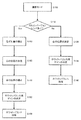
- Flowchart for explaining auto white balance control processing according to the first embodiment Schematic diagram for explaining division of video data according to the first embodiment
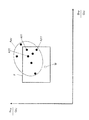
- FIG. 6 is a diagram for explaining calculation of a white position in a 2D video signal according to the first embodiment
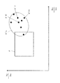
- FIG. 10 is a diagram for explaining calculation of a white position in a 3D video signal according to the first embodiment (part 1);
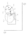
- FIG. 2 is a diagram for explaining calculation of a white position in a 3D video signal according to the first embodiment (part 2);
- FIG. 9 is a schematic diagram for explaining calculation of a white position in a 3D image in the digital video camera according to the second embodiment. Flowchart for explaining auto white balance control processing according to the second embodiment.
- Embodiment 1 in which the present invention is applied to a digital video camera will be described with reference to the drawings.
- FIG. 1 is a perspective view showing a state in which a 3D conversion lens 500 is attached to the digital video camera 100.
- the 3D conversion lens 500 can be attached to and detached from the connection part 640 (attachment part) of the digital video camera 100.
- the digital video camera 100 can magnetically detect the connection (attachment) of the 3D conversion lens 500 by the detection switch 290 (see FIG. 2).
- the 3D conversion lens 500 includes a right-eye lens that guides light for forming a right-eye subject image in a 3D (three-dimensions) image to the optical system of the digital video camera 100, and light for forming a left-eye subject image. And a left-eye lens for guiding the lens to the optical system.
- the light incident through the 3D conversion lens 500 is incident on the CCD image sensor 180 of the digital video camera 100, and thereby, for example, as a side-by-side 3D image, the subject image for the right eye and the left eye on the CCD image sensor 180. And a subject image are formed simultaneously.
- FIG. 2 is a block diagram illustrating a configuration of the digital video camera 100.
- the digital video camera 100 includes an optical system 101, a CCD image sensor 180, an image processing unit 190, a liquid crystal monitor 270, a detector 120, a zoom motor 130, an OIS actuator 150, a detector 160, a memory 200, a controller 210, a zoom lever 260, An operation member 250, an internal memory 280, a gyro sensor 220, a card slot 230, and a detection switch 290 are included.
- the digital video camera 100 captures a subject image formed by the optical system 101 with a CCD image sensor 180.
- the video data generated by the CCD image sensor 180 is subjected to various processes by the image processing unit 190 and stored in the memory card 240.
- the video data stored in the memory card 240 can be displayed on the liquid crystal monitor 270.
- the configuration of the digital video camera 100 will be described in detail.
- the optical system 101 of the digital video camera 100 includes a zoom lens 110, an OIS 140, and a focus lens 170.
- the zoom lens 110 can enlarge or reduce the subject image by moving along the optical axis of the optical system 101.
- the focus lens 170 adjusts the focus of the subject image by moving along the optical axis of the optical system 101.
- the OIS 140 has a correction lens that can move in a plane perpendicular to the optical axis.
- the OIS 140 reduces the shake of the subject image by driving the correction lens in a direction that cancels the shake of the digital video camera 100.
- the zoom motor 130 drives the zoom lens 110.
- the zoom motor 130 may be realized by a pulse motor, a DC motor, a linear motor, a servo motor, or the like.
- the zoom motor 130 may drive the zoom lens 110 via a mechanism such as a cam mechanism or a ball screw.
- the detector 120 detects where the zoom lens 110 exists on the optical axis.
- the detector 120 outputs a signal related to the position of the zoom lens by a switch such as a brush in accordance with the movement of the zoom lens 110 in the optical axis direction.
- the OIS actuator 150 drives the correction lens in the OIS 140 in a plane perpendicular to the optical axis.
- the OIS actuator 150 can be realized by a planar coil or an ultrasonic motor.
- the detector 160 detects the amount of movement of the correction lens in the OIS 140.
- the CCD image sensor 180 captures a subject image formed by the optical system 101 and generates video data.
- the CCD image sensor 180 performs various operations such as exposure, transfer, and electronic shutter.
- the image processing unit 190 performs various processes on the video data generated by the CCD image sensor 180.
- the image processing unit 190 generates video data to be displayed on the liquid crystal monitor 270 or generates video data to be re-stored in the memory card 240.
- the image processing unit 190 performs processing such as gamma correction, white balance correction, and flaw correction on the video data generated by the CCD image sensor 180.
- the image processing unit 190 applies H.264 to the video data generated by the CCD image sensor 180.
- the video data is compressed by a compression format compliant with the H.264 standard or the MPEG2 standard.
- the image processing unit 190 can be realized by a DSP or a microcomputer.
- the controller 210 is a control means for controlling the operation of the entire digital video camera.
- the controller 210 can be realized by a semiconductor element or the like.
- the controller 210 may be configured only by hardware, or may be realized by combining hardware and software.
- the controller 210 can be realized by a microcomputer or the like.
- the memory 200 functions as a work memory for the image processing unit 190 and the controller 210.
- the memory 200 can be realized by, for example, a DRAM or a ferroelectric memory.
- the liquid crystal monitor 270 can display an image indicated by the video data generated by the CCD image sensor 180 and an image indicated by the video data read from the memory card 240.
- the memory card 240 is detachable from the card slot 230.
- the card slot 230 can be mechanically and electrically connected to the memory card 240.
- the memory card 240 includes a flash memory, a ferroelectric memory, and the like, and can store data.
- controller 210 attaches 3D conversion lens 500 to digital video camera 100 based on a signal from detection switch 290. It is judged whether it is (S110). If it is determined that the 3D conversion lens 500 is not attached, the controller 210 performs auto white balance processing for 2D video signals (S120 to S140).
- the average value of the color intensity (brightness) of a plurality of red pixels included in the horizontal x-th and vertical y-th block BLxy is referred to as “average red data Rxy”.
- the average value of the color intensity (brightness) of the plurality of green pixels included in the horizontal x-th and vertical y-th block BLxy is referred to as “average green data Gxy”.
- An average value of color intensities (brightness) of a plurality of blue pixels included in the horizontal x-th and vertical y-th block BLxy is referred to as “average blue data Bxy”.
- the average red data Rxy, the average green data Gxy, and the average blue data Bxy are collectively referred to as “average color data Hxy”.
- the controller 210 calculates Bxy / Gxy, Rxy / Gxy based on the average color data Hxy (Rxy, Gxy, Bxy) of each block BLxy input from the image processing unit 190.
- Bxy / Gxy and Rxy / Gxy are appropriately referred to as “color data Axy”.
- the controller 210 When the gain is calculated, the controller 210 performs white balance processing on the video data (data taken from each pixel of the CCD image sensor 180) based on the calculated gain (S140).
- the blue component (B) tends to be larger than the red component (R) and the green component (G). Therefore, when the 3D conversion lens 500 is attached and photographed, the average red data Rxy and the average green data Gxy constituting the average color data Hxy are not changed much, but the 3D conversion lens 500 is attached to the average blue data Bxy. The image is more emphasized and bluish than when taken without. Therefore, as shown in FIG. 6, the value of Bxy / Gxy out of Bxy / Gxy and Rxy / Gxy constituting the color data Axy calculated based on the average color data Hxy is not attached to the 3D conversion lens 500. Most of the color data Axy protrudes from a frame F that is larger than the time and indicates a range close to white. For this reason, the position of white in the video data cannot be detected accurately. Therefore, the white balance cannot be adjusted satisfactorily.
- the controller 210 corrects each color data of the captured image by the amount of color misregistration when the 3D conversion lens 500 is attached (S150). Information on the color misregistration amount is stored in the internal memory 280 in advance.
- the color data A′xy that is, (B′xy / G′xy, R′xy / G′xy) is calculated based on the average color data H′xy.
- the controller 210 performs a correction to subtract the color misregistration amount ( ⁇ , ⁇ ) from the color data A′xy as shown by the arrow ⁇ 1 in step S150. That is, the position of the color data A′xy is moved by the amount of color misregistration ( ⁇ , ⁇ ) in the direction of the arrow ⁇ 1.
- the controller 210 can obtain the white position W ′′ based on the corrected color data A ′′ xy by the same algorithm (the algorithm in Step S120) as when the 3D conversion lens 500 is not attached.
- the controller 210 determines a white position W ′′ based on a plurality of corrected color data A ′′ xy (S160). In this case, the white position W ′′ when the 3D conversion lens 500 is not attached is determined.
- the process in step S160 is the same as the process in step S120.
- the controller 210 corrects the calculated white position W ′′ when the 3D conversion lens 500 is mounted. Specifically, the controller 210 performs correction for adding the amount of color misregistration ( ⁇ , ⁇ ) to the white position (coordinates) W ′′ as indicated by an arrow ⁇ 2 in FIG. By this correction, the position of white moves from W ′′ to W ′ by the amount of color misregistration ( ⁇ , ⁇ ) in the direction of arrow ⁇ 2.
- the controller 210 performs white balance processing on the video data based on the calculated gain (S190).
- the digital video camera 100 uses the white position W ′′ obtained based on the corrected color data A ′′ xy as the white position W ′ when the 3D conversion lens 500 is attached. The gain is calculated based on the corrected white position W ′.
- the digital video camera 100 includes a CCD image sensor 180 that captures a subject image and generates video data, and a white balance for the video data generated by the CCD image sensor 180 based on a predetermined algorithm.
- a controller 210 that performs processing, an image processing unit 190, and a connection unit 640 that can connect a 3D conversion lens 500 capable of simultaneously forming a subject image for the left eye and a subject image for the right eye on the CCD image sensor 180.
- the controller 210 performs white balance processing based on a different algorithm depending on whether or not the 3D conversion lens 500 is connected to the connection unit 640.
- white balance processing can be performed based on different algorithms depending on whether or not the 3D conversion lens 500 is connected to the connection unit 640. Thereby, the optimal white balance processing can be performed regardless of whether or not the 3D conversion lens 500 is attached.
- the process by the second algorithm is a process of correcting the position in the color coordinate system of the color data A′xy of the video data in which the color shift has occurred through the 3D conversion lens 500 so that the color shift is eliminated.
- steps S120, S130, and S140 of the first algorithm and steps S160, S180, and S190 of the second algorithm can be configured in common.
- steps S150 and S170 exist in the second algorithm. Therefore, the white balance processing for the 2D video signal and the white balance processing for the 3D video signal in which the color shift is caused by attaching the 3D conversion lens 500 can be shared as much as possible.
- the conventional white balance processing method for 2D video signals can be effectively used in the white balance processing of 3D video signals in which color misregistration has occurred by attaching the 3D conversion lens 500.
- FIG. 8 is a diagram for explaining the calculation of the white position in the 3D video signal in the digital video camera according to the second embodiment.
- the color data is moved (the position of the color data is corrected) when calculating the white position.
- the color data Axy is calculated when calculating the white position. Without moving, as shown in FIG. 8, the frame F indicating a range close to white is moved (the position of the frame F is corrected).
- FIG. 9 is a flowchart for explaining the auto white balance control process according to the second embodiment.
- the processing of steps S150 and S170 in the white balance processing of 3D video in the first embodiment is not performed, and the processing of step S155 is added.
- step S155 as shown in FIG. 8, a frame F indicating a range close to white is moved in a predetermined direction by a predetermined amount (frame F ′).
- This predetermined direction is the direction opposite to the direction in which the color data is moved in the first embodiment, and the predetermined amount is the same amount ( ⁇ , ⁇ ) as in the first embodiment.
- the controller 210 when the 3D conversion lens 500 is not connected to the connection unit 640, the controller 210 performs white balance processing based on the first algorithm, and the connection unit When the 3D conversion lens 500 is connected to 640, white balance processing is performed based on the second algorithm.
- the processing by the first algorithm is the same as that in the first embodiment (see FIG. 5).
- the area indicated by the frame F set in the color coordinate system in which the horizontal axis is Bxy / Gxy and the vertical axis is Rxy / Gxy is the color data A resulting from the connection of the 3D conversion lens 500.
- steps S120, S130, and S140 of the first algorithm and steps S160, S180, and S190 of the second algorithm can be configured in common.
- step S155 exists in the second algorithm. Therefore, the white balance processing for the 2D video signal and the white balance processing for the 3D video signal in which the color shift is caused by attaching the 3D conversion lens 500 can be shared as much as possible.
- the conventional white balance processing method for 2D video signals can be effectively used in the white balance processing of 3D video signals in which color misregistration has occurred by attaching the 3D conversion lens 500.
- Embodiments Embodiments 1 and 2 have been described as embodiments of the present invention. However, the present invention is not limited to these. Other embodiments of the present invention will be described collectively in this section.
- the blue component (B) tends to be larger than the red component (R) and the green component (G) due to the characteristics of the optical system of the 3D conversion lens 500 has been described. It is not limited. For example, depending on the characteristics of the optical system of the 3D conversion lens 500, one of the red component (R), the green component (G), and the blue component (B), or two components with respect to the other components. It can be applied when it is relatively large or small. That is, the present invention can be widely applied when the balance of the red component (R), the green component (G), and the blue component (B) is not equal due to the characteristics of the optical system of the 3D conversion lens 500.
- the CCD image sensor 180 is exemplified as the imaging means, but the present invention is not limited to this.
- it may be composed of a CMOS image sensor or an NMOS image sensor.
- the present invention can cope with color misregistration when a teleconversion lens or a wide conversion lens is connected.
- the present invention can be applied to an imaging apparatus such as a digital video camera or a digital still camera.
Abstract
Description
本発明をデジタルビデオカメラに適用した実施の形態1について図面を用いて説明する。
本実施の形態にかかるデジタルビデオカメラ100の概要について図1を用いて説明する。図1は、デジタルビデオカメラ100に3Dコンバージョンレンズ500を取り付けた状態を示す斜視図である。
本実施の形態にかかるデジタルビデオカメラ100の電気的構成について、図2を用いて説明する。図2は、デジタルビデオカメラ100の構成を示すブロック図である。デジタルビデオカメラ100は、光学系101、CCDイメージセンサー180、画像処理部190、液晶モニタ270、検出器120、ズームモータ130、OISアクチュエータ150、検出器160、メモリ200、コントローラー210、ズームレバー260、操作部材250、内部メモリ280、ジャイロセンサー220、カードスロット230、及び検出スイッチ290を有する。デジタルビデオカメラ100は、光学系101により形成された被写体像をCCDイメージセンサー180で撮像する。CCDイメージセンサー180で生成された映像データは、画像処理部190で各種処理が施され、メモリカード240に格納される。また、メモリカード240に格納された映像データは、液晶モニタ270で表示可能である。以下、デジタルビデオカメラ100の構成を詳細に説明する。
本実施の形態にかかるデジタルビデオカメラ100におけるオートホワイトバランス制御について図3~図7を用いて説明する。図3は、オートホワイトバランス処理の制御処理を説明するためのフローチャートである。図4は、映像データの分割を説明するための模式図である。図5は、2D映像信号における白の位置の算出を説明するための図である。図6は、3D映像信号における白の位置の算出を説明するための図(その1)、図7は、3D映像信号における白の位置の算出を説明するための図(その2)である。
実施の形態1のデジタルビデオカメラ100は、被写体像を撮像して映像データを生成するCCDイメージセンサー180と、CCDイメージセンサー180により生成された映像データに対して所定のアルゴリズムに基づいてホワイトバランス処理を行うコントローラー210及び画像処理部190と、CCDイメージセンサー180上に左目用の被写体像と右目用の被写体像とを同時に形成可能な3Dコンバージョンレンズ500を接続可能な接続部640と、を備え、コントローラー210は、接続部640に3Dコンバージョンレンズ500が接続されているか否かに応じて、異なるアルゴリズムに基づいてホワイトバランス処理を行う。
本発明をデジタルビデオカメラに適用した別の実施の形態について図面を用いて説明する。図8は、第2の実施の形態にかかるデジタルビデオカメラにおいて、3D映像信号における白の位置の算出を説明するための図である。実施の形態1では、白の位置を算出する際、色データを移動させた(色データの位置を補正した)が、実施の形態2では、白の位置を算出する際、色データAxyについては移動させず、図8に示すように、白色に近い範囲を示す枠Fを移動させる(枠Fの位置を補正する)。
本発明の実施の形態として、実施の形態1、2を説明した。しかし、本発明は、これらには限定されない。本発明の他の実施の形態を本欄にまとめて説明する。
110 ズームレンズ
120 検出器
130 ズームモータ
140 OIS
150 OISアクチュエータ
160 検出器
170 フォーカスレンズ
180 CCDイメージセンサー
190 画像処理部
200 メモリ
210 コントローラー
220 ジャイロセンサー
230 カードスロット
240 メモリカード
250 操作部材
260 ズームレバー
270 液晶モニタ
280 内部メモリ
290 検出スイッチ
640 接続部
Claims (3)
- 被写体像を撮像して映像データを生成する撮像素子と、
前記撮像素子により生成された映像データに対して所定のアルゴリズムに基づいてホワイトバランス処理を行う画像処理部と、
前記撮像素子上に左目用の被写体像と右目用の被写体像とを同時に形成可能な3Dコンバージョンレンズを接続可能な接続部と、
前記3Dコンバージョンレンズが前記接続部へ接続されたか否かを検出する検出部と、を備え、
前記画像処理部は、前記検出部の検出結果にしたがい、前記接続部に前記3Dコンバージョンレンズが接続されている場合と、接続されていない場合とで異なるアルゴリズムに基づいてホワイトバランス処理を行う、
撮像装置。 - 前記画像処理部は、前記接続部に前記3Dコンバージョンレンズが接続されていないときは、第1のアルゴリズムに基づいてホワイトバランス処理を行い、前記接続部に前記3Dコンバージョンレンズが接続されているときは、第2のアルゴリズムに基づいてホワイトバランス処理を行い、
前記第1のアルゴリズムによる処理は、前記映像データの色データのうち、所定の色座標系に設定された所定の領域に含まれる色データを抽出し、抽出された色データに基づいて白の位置を算出する処理と、算出された白の位置に基づいてホワイトバランス処理用のゲインを算出する処理と、算出されたゲインに基づいて前記映像データに対してホワイトバランスの調整を行う処理とを含み、
前記第2のアルゴリズムによる処理は、前記3Dコンバージョンレンズを介することにより色ずれが生じた前記映像データの色データの、所定の色座標系における位置を前記色ずれが解消されるように補正する処理と、前記補正後の色データのうち、前記所定の色座標系に設定された所定の領域に含まれる色データを抽出し、抽出された色データに基づいて白の位置を算出する処理と、算出された白の位置を前記色ずれに応じて補正する処理と、この補正された白の位置に基づいてホワイトバランス処理用のゲインを算出する処理と、算出されたゲインに基づいて前記映像データに対してホワイトバランスの調整を行う処理とを含む、
請求項1に記載の撮像装置。 - 前記画像処理部は、前記接続部に前記3Dコンバージョンレンズが接続されていないときは、第1のアルゴリズムに基づいてホワイトバランス処理を行い、前記接続部に前記3Dコンバージョンレンズが接続されているときは、第2のアルゴリズムに基づいてホワイトバランス処理を行い、
前記第1のアルゴリズムによる処理は、前記映像データの色データのうち、所定の色座標系に設定された所定の領域に含まれる色データを抽出し、抽出された色データに基づいて白の位置を算出する処理と、算出された白の位置に基づいてホワイトバランス処理用のゲインを算出する処理と、算出されたゲインに基づいて前記映像データに対してホワイトバランスの調整を行う処理とを含み、
前記第2のアルゴリズムによる処理は、所定の色座標系に設定された所定の領域を、前記3Dコンバージョンレンズを介することにより生じた前記映像データの色データの色ずれに応じて移動させる処理と、前記映像データの色データのうち前記移動させた所定の領域に含まれる色データを抽出し、抽出された色データに基づいて白の位置を算出する処理と、算出された白の位置に基づいてホワイトバランス処理用のゲインを算出する処理と、算出されたゲインに基づいて前記映像データに対してホワイトバランスの調整を行う処理とを含む、
請求項1に記載の撮像装置。
Priority Applications (2)
| Application Number | Priority Date | Filing Date | Title |
|---|---|---|---|
| JP2012527570A JPWO2012017596A1 (ja) | 2010-08-06 | 2011-06-24 | 撮像装置 |
| US13/814,251 US20130135436A1 (en) | 2010-08-06 | 2011-06-24 | Imaging apparatus |
Applications Claiming Priority (2)
| Application Number | Priority Date | Filing Date | Title |
|---|---|---|---|
| JP2010-177224 | 2010-08-06 | ||
| JP2010177224 | 2010-08-06 |
Publications (1)
| Publication Number | Publication Date |
|---|---|
| WO2012017596A1 true WO2012017596A1 (ja) | 2012-02-09 |
Family
ID=45559122
Family Applications (1)
| Application Number | Title | Priority Date | Filing Date |
|---|---|---|---|
| PCT/JP2011/003619 WO2012017596A1 (ja) | 2010-08-06 | 2011-06-24 | 撮像装置 |
Country Status (3)
| Country | Link |
|---|---|
| US (1) | US20130135436A1 (ja) |
| JP (1) | JPWO2012017596A1 (ja) |
| WO (1) | WO2012017596A1 (ja) |
Cited By (1)
| Publication number | Priority date | Publication date | Assignee | Title |
|---|---|---|---|---|
| JP2014022998A (ja) * | 2012-07-19 | 2014-02-03 | Canon Inc | 画像処理装置およびその制御方法 |
Citations (3)
| Publication number | Priority date | Publication date | Assignee | Title |
|---|---|---|---|---|
| JP2002218507A (ja) * | 2001-01-18 | 2002-08-02 | Olympus Optical Co Ltd | 撮像装置 |
| JP2003078794A (ja) * | 2001-09-05 | 2003-03-14 | Minolta Co Ltd | デジタルカメラ、交換レンズ、カメラボディ、および画像処理方法 |
| JP2006080892A (ja) * | 2004-09-09 | 2006-03-23 | Olympus Corp | 画像記録再生装置 |
Family Cites Families (1)
| Publication number | Priority date | Publication date | Assignee | Title |
|---|---|---|---|---|
| JP2002218506A (ja) * | 2001-01-18 | 2002-08-02 | Olympus Optical Co Ltd | 撮像装置 |
-
2011
- 2011-06-24 JP JP2012527570A patent/JPWO2012017596A1/ja not_active Withdrawn
- 2011-06-24 WO PCT/JP2011/003619 patent/WO2012017596A1/ja active Application Filing
- 2011-06-24 US US13/814,251 patent/US20130135436A1/en not_active Abandoned
Patent Citations (3)
| Publication number | Priority date | Publication date | Assignee | Title |
|---|---|---|---|---|
| JP2002218507A (ja) * | 2001-01-18 | 2002-08-02 | Olympus Optical Co Ltd | 撮像装置 |
| JP2003078794A (ja) * | 2001-09-05 | 2003-03-14 | Minolta Co Ltd | デジタルカメラ、交換レンズ、カメラボディ、および画像処理方法 |
| JP2006080892A (ja) * | 2004-09-09 | 2006-03-23 | Olympus Corp | 画像記録再生装置 |
Cited By (1)
| Publication number | Priority date | Publication date | Assignee | Title |
|---|---|---|---|---|
| JP2014022998A (ja) * | 2012-07-19 | 2014-02-03 | Canon Inc | 画像処理装置およびその制御方法 |
Also Published As
| Publication number | Publication date |
|---|---|
| US20130135436A1 (en) | 2013-05-30 |
| JPWO2012017596A1 (ja) | 2013-09-19 |
Similar Documents
| Publication | Publication Date | Title |
|---|---|---|
| JP5789793B2 (ja) | 3次元撮像装置、レンズ制御装置、およびプログラム | |
| WO2013031227A1 (ja) | 撮像装置およびプログラム | |
| TWI551113B (zh) | 3d成像模組及3d成像方法 | |
| JP5597525B2 (ja) | 立体映像撮像装置および立体映像撮像方法 | |
| JP6222514B2 (ja) | 画像処理装置、撮像装置、およびコンピュータブログラム | |
| JP2013165485A (ja) | 画像処理装置、撮像装置およびコンピュータブログラム | |
| WO2013027504A1 (ja) | 撮像装置 | |
| JP2011259168A (ja) | 立体パノラマ画像撮影装置 | |
| JP2010103895A (ja) | 撮像装置、複眼撮像装置及び撮像制御方法 | |
| JP4125331B2 (ja) | 撮像装置及びその制御方法 | |
| JP6432038B2 (ja) | 撮像装置 | |
| JP2015018225A (ja) | 光学機器、交換レンズ及び像ぶれ補正方法 | |
| JP2013046292A (ja) | 複眼撮像装置 | |
| JP2010135984A (ja) | 複眼撮像装置及び撮像方法 | |
| JP2012042912A (ja) | 立体画像撮像装置および立体画像撮像装置におけるレンズ駆動方法 | |
| JP6136019B2 (ja) | 動画像撮影装置、および、動画像撮影装置の合焦方法 | |
| WO2012017596A1 (ja) | 撮像装置 | |
| WO2012017585A1 (ja) | 撮像装置 | |
| JP2012054919A (ja) | 撮像装置 | |
| JP2011071712A (ja) | 立体撮像装置及び立体撮像方法 | |
| JP2013179580A (ja) | 撮像装置 | |
| JP2016178632A (ja) | 撮像装置、画像処理装置および画像処理方法 | |
| JP2012212965A (ja) | 撮像装置及び交換レンズ | |
| JP2011172047A (ja) | 撮像装置 | |
| JP2011188394A (ja) | 撮像装置 |
Legal Events
| Date | Code | Title | Description |
|---|---|---|---|
| 121 | Ep: the epo has been informed by wipo that ep was designated in this application |
Ref document number: 11814236 Country of ref document: EP Kind code of ref document: A1 |
|
| WWE | Wipo information: entry into national phase |
Ref document number: 2012527570 Country of ref document: JP |
|
| WWE | Wipo information: entry into national phase |
Ref document number: 13814251 Country of ref document: US |
|
| NENP | Non-entry into the national phase |
Ref country code: DE |
|
| 122 | Ep: pct application non-entry in european phase |
Ref document number: 11814236 Country of ref document: EP Kind code of ref document: A1 |