WO2012014969A1 - モールドモータ及びこれを搭載した移動体 - Google Patents
モールドモータ及びこれを搭載した移動体 Download PDFInfo
- Publication number
- WO2012014969A1 WO2012014969A1 PCT/JP2011/067235 JP2011067235W WO2012014969A1 WO 2012014969 A1 WO2012014969 A1 WO 2012014969A1 JP 2011067235 W JP2011067235 W JP 2011067235W WO 2012014969 A1 WO2012014969 A1 WO 2012014969A1
- Authority
- WO
- WIPO (PCT)
- Prior art keywords
- stator
- motor
- groove
- resin
- molded
- Prior art date
- Legal status (The legal status is an assumption and is not a legal conclusion. Google has not performed a legal analysis and makes no representation as to the accuracy of the status listed.)
- Ceased
Links
Images









Classifications
-
- H—ELECTRICITY
- H02—GENERATION; CONVERSION OR DISTRIBUTION OF ELECTRIC POWER
- H02K—DYNAMO-ELECTRIC MACHINES
- H02K5/00—Casings; Enclosures; Supports
- H02K5/04—Casings or enclosures characterised by the shape, form or construction thereof
- H02K5/08—Insulating casings
-
- B—PERFORMING OPERATIONS; TRANSPORTING
- B60—VEHICLES IN GENERAL
- B60L—PROPULSION OF ELECTRICALLY-PROPELLED VEHICLES; SUPPLYING ELECTRIC POWER FOR AUXILIARY EQUIPMENT OF ELECTRICALLY-PROPELLED VEHICLES; ELECTRODYNAMIC BRAKE SYSTEMS FOR VEHICLES IN GENERAL; MAGNETIC SUSPENSION OR LEVITATION FOR VEHICLES; MONITORING OPERATING VARIABLES OF ELECTRICALLY-PROPELLED VEHICLES; ELECTRIC SAFETY DEVICES FOR ELECTRICALLY-PROPELLED VEHICLES
- B60L50/00—Electric propulsion with power supplied within the vehicle
- B60L50/20—Electric propulsion with power supplied within the vehicle using propulsion power generated by humans or animals
-
- B—PERFORMING OPERATIONS; TRANSPORTING
- B62—LAND VEHICLES FOR TRAVELLING OTHERWISE THAN ON RAILS
- B62M—RIDER PROPULSION OF WHEELED VEHICLES OR SLEDGES; POWERED PROPULSION OF SLEDGES OR SINGLE-TRACK CYCLES; TRANSMISSIONS SPECIALLY ADAPTED FOR SUCH VEHICLES
- B62M7/00—Motorcycles characterised by position of motor or engine
- B62M7/12—Motorcycles characterised by position of motor or engine with the engine beside or within the driven wheel
-
- H—ELECTRICITY
- H02—GENERATION; CONVERSION OR DISTRIBUTION OF ELECTRIC POWER
- H02K—DYNAMO-ELECTRIC MACHINES
- H02K1/00—Details of the magnetic circuit
- H02K1/06—Details of the magnetic circuit characterised by the shape, form or construction
- H02K1/12—Stationary parts of the magnetic circuit
- H02K1/14—Stator cores with salient poles
- H02K1/146—Stator cores with salient poles consisting of a generally annular yoke with salient poles
- H02K1/148—Sectional cores
-
- H—ELECTRICITY
- H02—GENERATION; CONVERSION OR DISTRIBUTION OF ELECTRIC POWER
- H02K—DYNAMO-ELECTRIC MACHINES
- H02K3/00—Details of windings
- H02K3/04—Windings characterised by the conductor shape, form or construction, e.g. with bar conductors
- H02K3/18—Windings for salient poles
-
- H—ELECTRICITY
- H02—GENERATION; CONVERSION OR DISTRIBUTION OF ELECTRIC POWER
- H02K—DYNAMO-ELECTRIC MACHINES
- H02K3/00—Details of windings
- H02K3/46—Fastening of windings on the stator or rotor structure
- H02K3/52—Fastening salient pole windings or connections thereto
- H02K3/521—Fastening salient pole windings or connections thereto applicable to stators only
- H02K3/522—Fastening salient pole windings or connections thereto applicable to stators only for generally annular cores with salient poles
-
- H—ELECTRICITY
- H02—GENERATION; CONVERSION OR DISTRIBUTION OF ELECTRIC POWER
- H02K—DYNAMO-ELECTRIC MACHINES
- H02K7/00—Arrangements for handling mechanical energy structurally associated with dynamo-electric machines, e.g. structural association with mechanical driving motors or auxiliary dynamo-electric machines
- H02K7/006—Structural association of a motor or generator with the drive train of a motor vehicle
-
- B—PERFORMING OPERATIONS; TRANSPORTING
- B60—VEHICLES IN GENERAL
- B60L—PROPULSION OF ELECTRICALLY-PROPELLED VEHICLES; SUPPLYING ELECTRIC POWER FOR AUXILIARY EQUIPMENT OF ELECTRICALLY-PROPELLED VEHICLES; ELECTRODYNAMIC BRAKE SYSTEMS FOR VEHICLES IN GENERAL; MAGNETIC SUSPENSION OR LEVITATION FOR VEHICLES; MONITORING OPERATING VARIABLES OF ELECTRICALLY-PROPELLED VEHICLES; ELECTRIC SAFETY DEVICES FOR ELECTRICALLY-PROPELLED VEHICLES
- B60L2200/00—Type of vehicles
- B60L2200/12—Bikes
-
- B—PERFORMING OPERATIONS; TRANSPORTING
- B60—VEHICLES IN GENERAL
- B60L—PROPULSION OF ELECTRICALLY-PROPELLED VEHICLES; SUPPLYING ELECTRIC POWER FOR AUXILIARY EQUIPMENT OF ELECTRICALLY-PROPELLED VEHICLES; ELECTRODYNAMIC BRAKE SYSTEMS FOR VEHICLES IN GENERAL; MAGNETIC SUSPENSION OR LEVITATION FOR VEHICLES; MONITORING OPERATING VARIABLES OF ELECTRICALLY-PROPELLED VEHICLES; ELECTRIC SAFETY DEVICES FOR ELECTRICALLY-PROPELLED VEHICLES
- B60L2200/00—Type of vehicles
- B60L2200/32—Waterborne vessels
-
- B—PERFORMING OPERATIONS; TRANSPORTING
- B62—LAND VEHICLES FOR TRAVELLING OTHERWISE THAN ON RAILS
- B62K—CYCLES; CYCLE FRAMES; CYCLE STEERING DEVICES; RIDER-OPERATED TERMINAL CONTROLS SPECIALLY ADAPTED FOR CYCLES; CYCLE AXLE SUSPENSIONS; CYCLE SIDECARS, FORECARS, OR THE LIKE
- B62K2202/00—Motorised scooters
-
- B—PERFORMING OPERATIONS; TRANSPORTING
- B62—LAND VEHICLES FOR TRAVELLING OTHERWISE THAN ON RAILS
- B62K—CYCLES; CYCLE FRAMES; CYCLE STEERING DEVICES; RIDER-OPERATED TERMINAL CONTROLS SPECIALLY ADAPTED FOR CYCLES; CYCLE AXLE SUSPENSIONS; CYCLE SIDECARS, FORECARS, OR THE LIKE
- B62K2204/00—Adaptations for driving cycles by electric motor
-
- H—ELECTRICITY
- H02—GENERATION; CONVERSION OR DISTRIBUTION OF ELECTRIC POWER
- H02K—DYNAMO-ELECTRIC MACHINES
- H02K2203/00—Specific aspects not provided for in the other groups of this subclass relating to the windings
- H02K2203/12—Machines characterised by the bobbins for supporting the windings
-
- Y—GENERAL TAGGING OF NEW TECHNOLOGICAL DEVELOPMENTS; GENERAL TAGGING OF CROSS-SECTIONAL TECHNOLOGIES SPANNING OVER SEVERAL SECTIONS OF THE IPC; TECHNICAL SUBJECTS COVERED BY FORMER USPC CROSS-REFERENCE ART COLLECTIONS [XRACs] AND DIGESTS
- Y02—TECHNOLOGIES OR APPLICATIONS FOR MITIGATION OR ADAPTATION AGAINST CLIMATE CHANGE
- Y02T—CLIMATE CHANGE MITIGATION TECHNOLOGIES RELATED TO TRANSPORTATION
- Y02T10/00—Road transport of goods or passengers
- Y02T10/60—Other road transportation technologies with climate change mitigation effect
- Y02T10/64—Electric machine technologies in electromobility
Definitions
- the present invention relates to a molded motor in which an annular stator having a stator core and a coil is covered and molded with a mold resin.
- the present invention also relates to a movable body including an electric vehicle equipped with this molded motor.
- a molded motor has been developed in which an annular stator (stator) having a stator core and a coil (winding) is covered and molded with a mold resin.
- a rotor (rotor) having permanent magnets is disposed on the inside of the stator molded by this mold resin, and is rotatably supported on the stator.
- FIG. 1 In the permanent magnet type motor described in Patent Documents 1 and 2, a groove extending in the motor axial direction is formed at a position facing the permanent magnet of the tooth tip of the stator. Forming the groove acts to reduce the cogging torque by suitably balancing the number of magnetic poles and the number of coils.
- the molded motor coats and molds the stator with the mold resin
- the surface of the portion facing the permanent magnet of the stator is not coated with the mold resin in order to avoid the decrease of the motor output and efficiency.
- the stator is exposed on the inner circumferential surface.
- a molded motor when forming a groove for cogging torque protection as in the permanent magnet type motor described in Patent Documents 1 and 2 at a position facing the permanent magnet of the stator, only in the portion of this groove Mold resin may flow.
- the present invention has been made in view of the above points, and while suppressing the cost increase of the mold and the decrease in efficiency of the molding operation, the scattering of the mold resin small pieces inside the motor causing the rotational failure and breakage of the motor It is an object of the present invention to provide a molded motor with higher reliability which can be avoided. Another object of the present invention is to provide a movable body including a highly reliable electric vehicle provided with such a molded motor.
- the present invention is a molded motor in which an annular stator having a stator core and a coil is covered and molded with a mold resin, and the stator core is rotatably supported on the stator.
- a groove portion extending in the axial direction of the motor provided at a position facing the rotor, and a resin inflow prevention portion for preventing inflow of the mold resin into the groove portion are provided.
- the resin inflow blocking portion is formed in the groove portion formed in the portion of the stator facing the permanent magnet of the rotor as a measure against cogging torque, so that the mold resin is prevented from flowing into the groove portion. This can prevent molding of a mold resin piece in the shape of a groove that is easily scattered in the motor.
- the resin inflow preventing portion is provided at both ends in the motor axial direction of the groove portion, and a mold for forming a rotor accommodating portion for accommodating the rotor when molding the mold resin. , And its tip was in contact.
- the resin inflow blocking portion is provided at both ends in the motor circumferential direction of a portion of the stator core facing the rotor, and the rotor is accommodated when the molding resin is molded.
- the tip of the die is in contact with the die for forming the part.
- the resin inflow blocking portion is formed at both ends of the stator core in the motor circumferential direction of the portion facing the rotor, the mold resin is prevented from flowing into the groove along the motor circumferential direction of the portion. .
- the stator core includes stator teeth provided with the groove portions and arranged in a plurality in an annular manner in the circumferential direction of the motor, and the resin inflow preventing portion corresponds to each of the plurality of stator teeth.
- the resin inflow blocking portions provided corresponding to each of the adjacent stator teeth are connected to one another.
- the gap between the resin inflow preventing portions of the adjacent stator teeth is eliminated with respect to the plurality of stator teeth annularly arranged in the circumferential direction of the motor. Accordingly, the mold resin is prevented from flowing into the groove from between the adjacent resin inflow blocking portion and the resin inflow blocking portion.
- an electric insulating member is provided between the stator core and the coil, and in the resin inflow blocking portion, a portion of the electric insulating member radially inward toward the rotor housing portion It was decided to be composed of an extending rib portion.
- the resin inflow blocking portion is integrally formed with the electrical insulating member, it is not necessary to prepare and assemble a new member separately.
- the stator core is formed by laminating a plurality of steel plates at least in part in the motor axis direction, and the resin inflow blocking portion forms the stator core not provided with the groove portion. Made of a part of the steel plate.
- the resin inflow preventing portion is configured as a part of the steel plate forming the stator core, it is not necessary to prepare and assemble a new member separately.
- the stator core includes stator teeth provided with the groove portions and arranged in a plurality in an annular manner in the motor circumferential direction, and the steel plates without the groove portions are adjacent to each other between the stator teeth. It was decided to be integrated as one.
- the steel plate without the groove portion that is, the steel plate formed as the resin inflow preventing portion is integrally formed between the adjacent stator teeth, so that the mold resin is prevented from flowing into the groove portion.
- the strength can be increased.
- an electric insulating member is provided between the stator core and the coil, and the resin inflow preventing portion is extended so that a part of the electric insulating member fills the inside of the groove. It was decided to be configured.
- the resin inflow preventing portion is configured by filling the groove with a part of the electrical insulating member, there is no room for the mold resin to flow into the inside of the groove.
- the molded motor is mounted on a movable body including an electric vehicle.
- the term "mobile” mentioned here includes not only electric vehicles such as electric bicycles, motorcycles, three-wheeled vehicles, and four-wheeled vehicles, but also vehicles such as boats such as motor boats and watercrafts, and the like. It uses a motor as a drive source, and includes a moving body that moves unattended without a person getting on board.
- the configuration of the present invention it is possible to avoid the scattering of mold resin particles inside the motor which causes the rotation failure or breakage of the motor while suppressing the cost increase of the mold and the efficiency reduction of the molding operation. It is possible to provide a molded motor with further improved reliability. Moreover, it is possible to provide a mobile including a highly reliable electric vehicle provided with such a molded motor.
- FIG. 2 is a front elevational view, in vertical section, of a rear wheel portion of the electrically powered vehicle shown in FIG. 1; It is a perspective view of a mold motor periphery shown in FIG. It is a perspective view which shows the state which decomposed
- FIG. 6 is a front elevational view in vertical section of a stator of the molded motor shown in FIG. 5; FIG.
- FIG. 7 is a perspective view of the stator of FIG. 6 showing a state before coating with a mold resin. It is a top view of the stator core of the stator shown in FIG. It is a top view of the stator teeth of the stator core shown in FIG.
- FIG. 7 is a partially enlarged vertical sectional front view of the vicinity of a stator core of the stator shown in FIG. 6;
- FIG. 8 is a partial enlarged perspective view showing the periphery of a groove portion of the stator of FIG. 7; It is a partially expanded perspective view which shows the groove part periphery of the stator of the molded motor which concerns on the 2nd Embodiment of this invention.
- FIG. 14 is a partially enlarged vertical cross-sectional front view of the vicinity of the stator core of the stator shown in FIG. 13, showing a state after coating with a mold resin.
- FIG. 14 is a partial enlarged perspective view showing the periphery of a groove portion of the stator of FIG. 13; It is a partially expanded perspective view which shows the groove part periphery of the stator of the molded motor which concerns on the 4th Embodiment of this invention.
- FIG. 18 is a partially enlarged vertical cross-sectional front view of the vicinity of the stator core of the stator shown in FIG. 17, showing a state after coating with a mold resin.
- FIG. 18 is a partial enlarged perspective view showing the periphery of a groove portion of the stator of FIG.
- FIG. 17 It is a perspective view of a stator of a molded motor concerning a 6th embodiment of the present invention, and shows a part of state before covering with mold resin.
- FIG. 23 is a partial enlarged perspective view showing the periphery of a groove portion of the stator of FIG. 22.
- FIG. 23 is a plan view of a portion of the stator shown in FIG. 22.
- FIG. 23 is a cross-sectional view of a portion of the stator shown in FIG. 22.
- FIG. 27 is a plan view of a portion of the stator shown in FIG. 26.
- FIG. 27 is a cross-sectional view of a portion of the stator shown in FIG. 26.
- FIG. 28 is a partial enlarged plan view of a part of the stator shown in FIG. 27.
- It is a perspective view of a stator of a molded motor concerning the 8th embodiment of the present invention, and shows a part of state before covering with mold resin.
- FIG. 31 is a plan view of a portion of the stator shown in FIG. 30.
- FIG. 31 is a partial enlarged plan view of a portion of the stator shown in FIG. 30.
- FIGS. 1 to 32 An embodiment of the present invention will be described based on FIGS. 1 to 32.
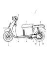
- FIG. 1 is a right side view showing an example of an electric vehicle equipped with a molded motor.
- An electric vehicle 1 which is a moving body is a motorcycle provided with a front wheel 2 and a rear wheel 3 as shown in FIG.
- the electric vehicle 1 has a main frame 4 and a swing arm 5 as main frameworks.
- a front end of the main frame 4 is bent upward, and the front end supports the front wheel 2 and the steering wheel 6 in a steerable manner.
- a seat 7 on which the driver can sit and a battery accommodating portion 8 are provided at a rear end side of the main frame 4 and at a substantially central portion in the front-rear direction of the electric vehicle 1.
- the battery storage portion 8 is provided below the seat 7 and can store a battery (not shown) therein.
- the seat 7 also serves as a lid of the battery storage portion 8 and is attached to the battery storage portion 8 in an openable / closable manner.
- a luggage rack 9 is provided at a position behind the seat 7 of the main frame 4 and above the rear wheel 3.
- the swing arm 5 extends rearward from below the seat 7 and the battery housing 8 at the rear of the main frame 4.
- the rear wheel 3 is supported at the rear end of the swing arm 5.
- the swing arm 5 is provided only on the right side of the rear wheel 3 and supports the rear wheel 3 in a cantilever state.
- the rear wheel 3 is a drive wheel, and a mold motor 20 for driving the rear wheel 3 is provided between the rear wheel 3 and the swing arm 5.
- the swing arm 5 is a support member having a rear end coupled to the front end of the molded motor 20 and supporting the rear wheel 3 via the molded motor 20.
- a suspension case 10 is provided outside the molded motor 20.
- a suspension unit 11 of the rear wheel 3 extends from the suspension case 10 toward the upper luggage platform 9.
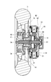
- FIG. 2 is a front elevational view of a vertical cross section of the rear wheel portion of the electric vehicle
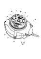
- FIG. 3 is a perspective view of the mold motor and its surroundings shown in FIG. 2
- FIG. 4 is a perspective view showing a state is there.
- FIG. 4 the drawing of the rotor and the reduction mechanism inside the molded motor is omitted.
- the suspension case 10, the molded motor 20, the speed reduction mechanism 30, the braking mechanism 40, and the rear are arranged in order from the right side of the rear wheel 3 in FIG. A wheel 3 is provided.
- the molded motor 20, the braking mechanism 40, and the rear wheel 3 are arranged coaxially with each other.
- Mold motor 20 is for an electric vehicle in which stator 50 (see FIGS. 6 and 7), which is an annular stator described later as shown in FIGS. 1, 3 and 4, is covered with insulating mold resin 21. It is a motor.
- the molded motor 20 has the axis of the stator 50 aligned with the axle 3 a of the rear wheel 3 and is disposed in the vicinity of the rear wheel 3.
- a rotor 22 having a permanent magnet (not shown) is provided inside the mold resin 21 as a rotor of a motor.
- the rotor 22 is disposed with its axis aligned with the axis of the stator 50 and is fixed to a rotatably provided motor shaft 23. Therefore, the rotor 22 is rotated by the drive of the molded motor 20, and the power is transmitted to the motor shaft 23.
- the reduction mechanism 30 is disposed at a position between the motor shaft 23 and the axle 3a.
- the reduction mechanism 30 is configured of, for example, a planetary gear mechanism.
- the braking mechanism 40 is a so-called drum type brake disposed in the vicinity of the wheel 3b of the rear wheel 3, and includes a brake shoe 41, a spring 42, a brake arm 43, and a brake cover 44 as shown in FIGS. There is.
- the brake shoe 41 is disposed inside the wheel 3b.
- the brake shoe 41 is spaced radially inward with respect to the wheel 3 b by the action of the spring 42.
- the brake shoe 41 is pushed outward in the radial direction with respect to the axle 3 a against the elastic force of the spring 42 by the rotation of the brake arm 43.
- the brake shoe 41 generates a frictional resistance between the wheel 3b and a drum (not shown) that rotates integrally with the wheel 3b, thereby braking the rotation of the wheel 3b, that is, the rear wheel 3.
- a brake cover 44 is attached as a lid to a portion of the wheel 3b where the brake shoe 41 is disposed, so that dust and the like do not enter inside (see FIG. 2).
- the brake cover 44 has a dustproof function with respect to the inside of the braking mechanism 40, and also has a function of holding a brake member such as the brake shoe 41, the spring 42, and the brake arm 43.
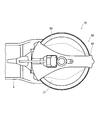
- FIGS. 5 to 11 are right side views of the molded motor portion
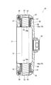
- FIG. 6 is a front elevational view of a vertical cross section of the stator of the molded motor
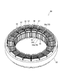
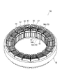
- FIG. 7 is a perspective view of the stator and shows a state before coating with molded resin
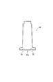
- FIG. 9 is a plan view of the stator teeth
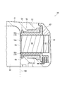
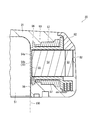
- FIG. 10 is a partially enlarged vertical sectional front view of the stator core and the vicinity of the stator core
- FIG. 11 is a partially enlarged perspective view showing the groove portion of the stator.
- the molded motor 20 includes a stator 50 and a motor case 60 as shown in FIGS. 5 and 6 in addition to the molded resin 21, the rotor 22 and the motor shaft 23 described above.
- the stator 50 has an annular shape as shown in FIGS. 6 and 7, and the periphery thereof is covered with an insulating mold resin 21.
- the mold resin 21 is made of, for example, a thermosetting resin containing glass fiber or the like.
- Inside the stator 50 there is provided a rotor accommodating portion 51 formed as a recessed portion recessed from the side of the rear wheel 3 in the mold resin 21.
- the rotor accommodating portion 51 has a cylindrical shape, and the rotor 22 having a permanent magnet is disposed in the rotor accommodating portion 51 (see FIG. 2).
- the motor case 60 is made of metal such as aluminum alloy, and provided so as to sandwich and hold the mold resin 21 covering the stator 50 inside.
- the motor case 60 is composed of two plate-like case members arranged to sandwich the mold resin 21 inside, that is, an inner case 61 and an outer case 62 shown in FIGS. As shown in FIG. 2, the inner case 61 is disposed on the rear wheel 3 side, and the outer case 62 is disposed on the suspension case 10 opposite to the rear wheel 3 side.
- the stator 50 has an annular shape as shown in FIGS. 6 and 7, and includes a stator core 52 shown in FIG.
- the stator core 52 includes an annular stator yoke 53 and stator teeth 54 projecting radially inward from an inner peripheral portion of the stator yoke 53.
- eighteen stator teeth 54 are arranged in a circle around the circumferential direction of the molded motor 20.
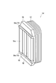
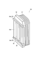
- a groove 55 is provided on the rotor facing surface 54 a which is a position facing the rotor 22 at the tip of the stator teeth 54.
- the groove 55 extends in the axial direction of the motor and is provided side by side in the circumferential direction of the motor, and acts to reduce the cogging torque by suitably balancing the number of magnetic poles of the molded motor 20 and the number of coils.
- An insulator 56 which is an electrical insulating member, is mounted on the outer periphery of the stator teeth 54. Furthermore, a wire is wound around the outside of the insulator 56 to form a coil 57.
- the insulator 56 is provided with rib portions 56a on both ends in the motor shaft direction of the groove portion 55 of the rotor facing surface 54a at the tip of the stator teeth 54.
- the rib portion 56 a is configured such that a portion of the insulator 56 extends radially inward toward the rotor accommodation portion 51.
- the surface of the rib portion 56 a facing the rotor accommodation portion 51 is flush with the rotor facing surface 54 a of the stator teeth 54.
- the rib 56 a When the stator 50 is covered and molded with the mold resin 21, the rib 56 a has its tip end in a mold 100 (drawn by a two-dot chain line) for forming the rotor accommodation portion 51 as shown in FIG. It comes in contact. As a result, the rib portion 56 a becomes a resin inflow blocking portion 70 that blocks the mold resin 21 from flowing into the groove 55 from both ends in the motor axial direction of the groove 55. And since this resin inflow prevention part 70 is comprised integrally with the insulator 56 as the rib part 56a, it is not necessary to prepare and assemble a new member separately.
- the resin inflow blocking portion 70 is formed in the groove portion 55 formed in the portion of the stator 50 facing the permanent magnet of the rotor 50 as a countermeasure against cogging torque. 21 is prevented from flowing in. As a result, it is possible to prevent molding of a mold resin piece in the shape of the groove 55 that is easily scattered in the molded motor 20 from being molded.
- the molded motor 20 with improved reliability can be provided.
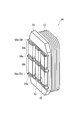
- FIG. 12 is a partially enlarged perspective view showing the periphery of the groove portion of the stator of the molded motor.
- the basic configuration of this embodiment is the same as that of the first embodiment described with reference to FIGS. 1 to 11. Therefore, the same reference numerals as in the first embodiment are used for the components common to the first embodiment. The description of the drawings and their explanations shall be omitted.
- the rib portion 56a of the insulator 56 protrudes radially inward from the rotor facing surface 54a of the stator teeth 54, as shown in FIG. According to this configuration, even if the length of the rib portion 56a extending inward in the radial direction becomes relatively short due to a manufacturing error of the insulator 56, the rib portion 56a does not extend from both ends in the motor axial direction of the groove portion 55.
- the resin inflow blocking portion 70 serves to prevent the mold resin 21 from flowing into the groove 55.
- FIG. 13 is a perspective view of a stator of a molded motor and shows a state before coating with a mold resin
- FIG. 14 is a partially enlarged vertical cross-sectional front view of the periphery of a stator core of the stator and shows a state after coating with a mold resin
- FIG. 15 is a partially enlarged perspective view showing the periphery of the groove portion of the stator.
- the basic configuration of this embodiment is the same as that of the first embodiment described with reference to FIGS. 1 to 11. Therefore, the same reference numerals as in the first embodiment are used for the components common to the first embodiment.
- the description of the drawings and their explanations shall be omitted.
- the insulator 56 is provided with a groove filling portion 56b in the groove 55 of the rotor facing surface 54a at the tip of the stator teeth 54.
- the groove filling portion 56 b is configured to extend so that a part of the insulator 56 fills the inside of the groove 55.
- the surfaces of the groove filling portion 56b of the insulator 56 and the portions at both ends in the motor axial direction face the rotor accommodating portion 51 are flush with the rotor facing surface 54a of the stator teeth 54.
- the groove filling portion 56 b of the insulator 56 becomes a resin inflow blocking portion 70 that prevents the mold resin 21 from flowing into the groove 55.
- the configuration of this embodiment since there is no room for the mold resin 21 to flow into the inside of the groove 55, it is possible to prevent molding of a mold resin piece in the shape of the groove 55 which is easily scattered in the mold motor 20.
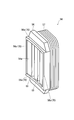
- FIG. 16 is a partial enlarged perspective view showing the periphery of the groove portion of the stator of the molded motor.
- the basic configuration of this embodiment is the same as that of the first embodiment described with reference to FIGS. 1 to 11. Therefore, the same reference numerals as in the first embodiment are used for the components common to the first embodiment. The description of the drawings and their explanations shall be omitted.
- the groove filling portion 56b of the insulator 56 protrudes radially inward from the rotor facing surface 54a of the stator teeth 54 as shown in FIG. According to this configuration, even if the length of the groove filling portion 56b extending inward in the radial direction becomes relatively short due to a manufacturing error of the insulator 56, the groove filling portion 56b is molded resin in the groove 55
- the resin inflow blocking unit 70 serves to block the flow of the fluid 21.
- FIG. 17 is a perspective view of a stator of a molded motor and shows a state before coating with a mold resin
- FIG. 18 is a plan view of a stator core of the stator
- FIG. 19 is an explanatory view showing a structure of stator teeth
- FIG. Fig. 21 is a partially enlarged perspective view showing the periphery of the groove portion of the stator, showing a state after coating with a mold resin in a partially enlarged vertical cross-sectional front view of the stator core and its periphery.
- FIGS. 17 is a perspective view of a stator of a molded motor and shows a state before coating with a mold resin
- FIG. 18 is a plan view of a stator core of the stator
- FIG. 19 is an explanatory view showing a structure of stator teeth
- FIG. Fig. 21 is a partially enlarged perspective view showing the periphery of the groove portion of the stator, showing a state after coating with a mold resin in
- stator teeth 54 of the stator 50 shown in FIG. 17 are integrally configured.
- the stator teeth 54 are formed by laminating a plurality of steel plates 58 in the axial direction of the motor as shown in FIGS.
- the steel plate 58 includes a connecting steel plate 58a and a single steel plate 58b.
- the connecting steel plates 58a are integrally configured between the adjacent stator teeth 54 as shown in FIG.
- the single steel plate 58 b has a shape corresponding to a single stator tooth 54.
- the connecting steel plates 58a are arranged, for example, by laminating one or two sheets at three positions in the motor axial direction both ends and the central portion of the stator teeth 54. For example, about 20 sheets of single steel plates 58b are stacked and arranged between them.
- the groove 55 of the rotor facing surface 54a at the tip of the stator teeth 54 is provided only in the single steel plate 58b. That is, a recess 55 having a cross-sectional shape corresponding to the groove 55 is formed in the single steel plate 58b, and the single steel plate 58b is stacked in the motor axial direction to form the stator teeth 54, thereby forming the groove 55 extending in the motor axial direction.
- the stator 50 is formed of gold for forming the rotor accommodating portion 51 as shown in FIG. It comes in contact with a mold 100 (drawn by a two-dot chain line).
- the connecting steel plate 58 a of the steel plate 58 becomes the resin inflow blocking portion 70 that prevents the mold resin 21 from flowing into the groove 55 from both ends in the motor axial direction of the groove 55.
- the resin inflow blocking portion 70 is configured as a part of the steel plate 58 forming the stator core 52, it is not necessary to prepare and assemble a new member separately. Further, since the connecting steel plates 58a formed as the resin inflow preventing portion 70 are integrally formed between the adjacent stator teeth 54, the strength of the stator core 52 is increased while preventing the mold resin 21 from flowing into the groove 55. Can.
- FIG. 22 is a perspective view of a stator of a molded motor and shows a part of a state before being coated with a mold resin
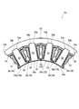
- FIG. 23 is a partial enlarged perspective view showing the periphery of a groove of the stator
- FIG. FIG. 25 is a cross-sectional view of a portion of the stator.
- the basic configuration of this embodiment is the same as that of the first embodiment described with reference to FIGS. 1 to 11. Therefore, the same reference numerals as in the first embodiment are used for the components common to the first embodiment.
- the description of the drawings and their explanations shall be omitted.
- the insulator 56 is a rib provided at both ends in the motor axial direction of the groove 55 of the rotor facing surface 54a at the tip of the stator teeth 54 (upper and lower sides of the groove 55 in FIGS. 22 and 23).
- rib portions 56c provided on both ends in the motor circumferential direction of the rotor facing surface 54a (left and right of the rotor facing surface 54a in FIGS. 22 and 23) are provided.
- the rib portion 56 c extends over both ends of the groove 55 in the motor axial direction. That is, the rib portions 56a and 56c are provided so as to surround the rotor facing surface 54a and the groove 55 on four sides.
- the rib portions 56a and 56c protrude radially inward from the rotor facing surface 54a of the stator teeth 54, as shown in FIGS. Further, as shown in FIG. 22, the rib portions 56a and 56c are individually provided corresponding to each of the plurality of stator teeth 54 annularly arranged in the circumferential direction of the motor.
- stator teeth 54 of the stator 50 are integrally formed by attaching a plurality of, for example, four adjacent stator teeth. Further, four stator teeth 54 are attached to one of the stator yokes 53 obtained by dividing the annular stator yoke 53 (see, for example, FIG. 8) into a plurality of pieces.
- stator teeth 54 have not yet been attached to the stator yoke 53.
- the insulators 56 are individually attached to the outer periphery of the four stator teeth 54.
- the insulator 56 is attached to the stator teeth 54 from the radial outer side.
- the coil 57 by which the electric wire was previously wound is formed in the outer side of the insulator 56. As shown in FIG.
- stator teeth 54 opposite to the side on which the rotor facing surface 54 a is provided is attached to the inner peripheral portion of the stator yoke 53.
- a fitting convex portion 54 b is provided at a position opposite to the side where the rotor facing surface 54 a of the stator teeth 54 is provided.
- the stator teeth 54 and the stator yoke 53 are coupled by engaging the fitting convex portion 54 b with the fitting concave portion 53 a provided at the corresponding position of the inner peripheral portion of the stator yoke 53.
- stator 50 shown in FIGS. 22, 24 and 25 part of the stator 50 shown in FIGS. 22, 24 and 25 is completed. Then, a plurality of parts of the stator 50 are arranged and joined along the motor circumferential direction to complete the stator 50 in a state before being covered with the mold resin 21 (see, for example, FIG. 7). Note that, as shown in FIGS. 24 and 25, the stator yoke 53 is individually provided with a connecting protrusion 53b and a connecting recess 53c for connecting to another stator yoke 53 adjacent in the motor circumferential direction (FIG. 22). (I omit drawing).
- the rib portions 56a and 56c cover and mold the stator 50 with the mold resin 21, a mold 100 (not shown in FIGS. 22 to 25) for forming the rotor accommodating portion 51 (for example, two points in FIG. The front end is in contact with the drawing).
- the rib portions 56a and 56c prevent resin resin 21 from flowing into groove portion 55 from both axial ends of groove portion 55 in the motor axial direction and further into groove portion 55 along the motor circumferential direction of rotor opposing surface 54a.
- the blocking unit 70 is formed.
- FIG. 26 is a perspective view of a stator of a molded motor and shows a part of a state before being coated with a mold resin
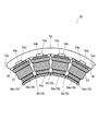
- FIG. 27 is a plan view of a part of the stator shown in FIG.
- FIG. 29 is a partial enlarged plan view of a part of the stator.
- the components common to these embodiments are denoted by the same reference numerals as before, and the description of the drawings and the components thereof The explanation shall be omitted.
- the insulator 56 is provided with rib portions 56a at both ends in the motor axial direction of the groove 55 of the rotor facing surface 54a at the tip of the stator teeth 54.
- the rib portion 56a is configured such that a portion of the insulator 56 extends radially inward and further extends along the motor circumferential direction.
- the rib portion 56a is individually provided corresponding to each of the plurality of stator teeth 54 annularly arranged in the circumferential direction of the motor.
- engaging portions 59 are provided at outer edge portions of both ends in the motor circumferential direction of the rib portion 56a.
- the engaging portion 59 extends in the axial direction of the motor over the two rib portions 56 a provided at both ends in the motor axial direction of the groove portion 55.
- a step is formed in the engaging portion 59 so that the engaging portions 59 of the adjacent insulators 56 engage with each other and are connected.
- the step of the engaging portion 59 is configured such that the engaging portions 59 can be engaged with each other when the adjacent insulators 56 are made to approach along the motor axial direction.
- the engaging portions 59 of the adjacent insulators 56 can be connected in close contact with each other.
- stator 50 a method of assembling the stator 50 will be described.
- the configuration of the stator teeth 54 and the stator yoke 53 of the stator 50 is the same as that of the sixth embodiment.
- stator teeth 54 have not yet been attached to the stator yoke 53.
- the insulators 56 are individually attached to the outer periphery of the four stator teeth 54.
- a portion of the four stator teeth 54 opposite to the side on which the rotor facing surface 54 a is provided is attached to the inner peripheral portion of the stator yoke 53.
- the stator teeth 54 are attached to the stator yoke 53 such that the engaging portions 59 of the adjacent insulators 56 are engaged with each other and connected in the motor circumferential direction.
- FIGS. 26 to 28 a part of the stator 50 shown in FIGS. 26 to 28 is completed. Then, a plurality of parts of the stator 50 are arranged and joined along the motor circumferential direction to complete the stator 50 in a state before being covered with the mold resin 21 (see, for example, FIG. 7).
- the engaging portions 59 of the adjacent insulators 56 are engaged with each other also when a plurality of parts of the stator 50 are arranged and coupled along the motor circumferential direction.
- the rib portion 56a which is the resin inflow blocking portion 70 is individually provided corresponding to each of the stator teeth 54 arranged in a ring in the circumferential direction of the motor, and corresponds to each adjacent stator teeth 54.
- Engaging portions 59 which are another resin inflow blocking portion 70 provided, are connected to each other.
- the gap between the engaging portions 59 of the stator teeth 54 adjacent to the plurality of stator teeth 54 annularly arranged in the circumferential direction of the motor is eliminated. Therefore, the mold resin 21 can be prevented from flowing into the groove 55 from between the adjacent engaging portion 59 and the engaging portion 59.
- FIG. FIG. 30 is a perspective view of a stator of a molded motor and shows a part of a state before coating with a mold resin
- FIG. 31 is a plan view of a part of the stator
- FIG. 32 is a partially enlarged plan view of a part of the stator It is.
- the same reference numerals as in the first embodiment are attached to the same components as those in the first embodiment. Description and description shall be omitted.
- the insulator 56 is provided with rib portions 56a on both ends in the motor axial direction of the groove 55 of the rotor facing surface 54a at the tip of the stator teeth 54. .
- the rib portion 56a is configured such that a portion of the insulator 56 extends radially inward and further extends along the motor circumferential direction.
- the rib portion 56a is individually provided corresponding to each of the plurality of stator teeth 54 annularly arranged in the circumferential direction of the motor.
- the stator teeth 54 of the stator 50 are integrally configured by attaching a plurality of adjacent ones, for example, four, to one stator yoke 53. And the engaging part 59 is provided in the outer edge part of the motor circumferential direction both ends of the adjacent rib part 56a of 4 insulators.
- the engaging portion 59 is not provided See FIG. 32, and FIG. 32 shows the stator teeth 54 on the right end side of FIGS. 30 and 31). That is, the rib portion 56 c extends over both ends in the motor shaft direction of the groove portion 55 at a position on the motor circumferential direction outer side of the rotor facing surface 54 a where the adjacent insulators 56 do not exist.
- the rib portions 56 a and 56 c and the engaging portion 59 become the resin inflow preventing portion 70, and can prevent the mold resin 21 from flowing into the groove 55.
- the mobile body mounted with the molded motor 20 has been described by taking the motorcycle as the electric vehicle 1 shown in FIG. 1 as an example, but the mobile body to be mounted is limited to the motorcycle It is not a problem, and it may be a three-wheeled motor vehicle or a four-wheeled motor vehicle.
- the mobile object to which the battery device of the present invention is applied may be a vehicle such as a boat such as a motor boat or a water toy, or a mobile object that uses a motor as a drive source and moves unattended without a person getting on board. .
- the present invention is applicable to molded motors in general.
Landscapes
- Engineering & Computer Science (AREA)
- Power Engineering (AREA)
- Transportation (AREA)
- Mechanical Engineering (AREA)
- Chemical & Material Sciences (AREA)
- Combustion & Propulsion (AREA)
- Iron Core Of Rotating Electric Machines (AREA)
- Insulation, Fastening Of Motor, Generator Windings (AREA)
- Manufacture Of Motors, Generators (AREA)
Abstract
モールドモータ20は、ステータコア52とコイル57とを有する環状のステータ50をモールド樹脂21によって被覆したモータであって、ステータコア52の、ステータ50に対して回転自在に支持されたロータ22と対向する箇所であるロータ対向面54aに設けられたモータ軸線方向に延びる溝部55と、溝部55へのモールド樹脂21の流入を阻止する樹脂流入阻止部70と、を備える。
Description
本発明は、ステータコアとコイルとを有する環状のステータをモールド樹脂によって被覆、成型したモールドモータに関する。また、このモールドモータを搭載した電動車両を含む移動体に関する。
近年、ステータコアとコイル(巻き線)とを有する環状のステータ(固定子)をモールド樹脂によって被覆、成型したモールドモータが開発されている。このモールド樹脂によって成型されたステータの内側に永久磁石を有するロータ(回転子)が配置され、ステータに対して回転自在に支持されている。
ここで、永久磁石式モータにおいては、ロータの永久磁石とステータコアとの間で働く磁気吸引力によって生じるトルク脈動であるコギングトルクの発生が問題となっている。そして、このコギングトルクに起因する無負荷時の振動や騒音、位置決め精度の低下などが課題となっている。
そこで、このような問題を回避すべくコギングトルクの低減を図った技術が提案され、その例を特許文献1及び2に見ることができる。特許文献1及び2に記載された永久磁石式モータは、ステータのティース先端部の永久磁石と対向する箇所にモータ軸線方向に延びる溝を形成している。この溝を形成することが、磁極数とコイル数とのバランスを好適にしてコギングトルクを低減させるよう作用している。
ここで、モールドモータはステータをモールド樹脂で被覆、成型する際、モータの出力や効率が低下するのを回避するため、ステータの永久磁石と対向する箇所の表面がモールド樹脂で被覆されることなくステータ内周面で露出するようにしている。このようなモールドモータにおいては、ステータの永久磁石と対向する箇所に、特許文献1及び2に記載された永久磁石式モータのようにコギングトルク対策の溝を形成する場合、この溝の部分にのみモールド樹脂が流れ込む可能性がある。
そして、上記コギングトルク対策の溝は比較的細長いので、この溝に流れ込んだモールド樹脂に十分な機械的強度が得られない虞がある。これにより、溝の流れ込んだモールド樹脂の小片が飛散する可能性がある。その結果、飛散、散乱したモールド樹脂の小片が回転するロータとステータとの間や、軸受部などに噛み込み、モータの回転が不調になったり、モータ自体が破損したりする問題を起こすことが懸念される。
そこで、上記コギングトルク対策の溝にモールド樹脂が流れ込まないようにするため、ステータをモールド樹脂により成型する際の金型に溝に対応した突起等を設けることが考えられる。しかしながら、金型にそのような突起を設ける場合、モールド樹脂が流れ込まないよう突起を高精度に形成する必要があるとともに、成型前にステータコアを金型内に配置するとき溝と突起とを合わせる作業が困難になる虞がある。これにより、金型の高コスト化や、成型作業の効率が低下する可能性が高い。
本発明は上記の点に鑑みなされたものであり、金型の高コスト化や成型作業の効率低下を抑制しながら、モータの回転不調や破損の原因となるモータ内部におけるモールド樹脂小片の散乱を回避することが可能な、一層信頼性が高められたモールドモータを提供することを目的とする。また、このようなモールドモータを備えた信頼性の高い電動車両を含む移動体を提供することを目的とする。
上記の課題を解決するため、本発明は、ステータコアとコイルとを有する環状のステータをモールド樹脂によって被覆、成型したモールドモータであって、前記ステータコアの、前記ステータに対して回転自在に支持されたロータと対向する箇所に設けられたモータ軸線方向に延びる溝部と、前記溝部への前記モールド樹脂の流入を阻止する樹脂流入阻止部と、を備えることとした。
この構成によれば、コギングトルク対策としてステータの、ロータの永久磁石と対向する箇所に形成した溝部に対して樹脂流入阻止部が形成されるので、溝部にモールド樹脂が流れ込むのが妨げられる。これにより、モータ内で飛散し易い溝部の形状のモールド樹脂小片が成型されるのを妨げることができる。
また、上記構成のモールドモータにおいて、前記樹脂流入阻止部は、前記溝部のモータ軸線方向両端に備えられ、前記モールド樹脂の成型のとき、前記ロータを収容するロータ収容部を形成するための型に、その先端が当接することとした。
この構成によれば、樹脂流入阻止部が溝部の両端に形成されるので、溝部の両端から溝部内にモールド樹脂が流れ込むのが妨げられる。
また、上記構成のモールドモータにおいて、前記樹脂流入阻止部は、前記ステータコアの、前記ロータと対向する箇所のモータ周方向両端に備えられ、前記モールド樹脂の成型のとき、前記ロータを収容するロータ収容部を形成するための型に、その先端が当接することとした。
この構成によれば、樹脂流入阻止部がステータコアの、ロータと対向する箇所のモータ周方向両端に形成されるので、その箇所のモータ周方向に沿って溝部内にモールド樹脂が流れ込むのが妨げられる。
また、上記構成のモールドモータにおいて、前記ステータコアは、前記溝部が設けられモータ周方向に環状に複数個並べられたステータティースを備え、前記樹脂流入阻止部は、前記複数のステータティース各々に対応して個別に設けられるとともに、隣り合う前記ステータティース各々に対応して設けられた前記樹脂流入阻止部どうしが連結されていることとした。
この構成によれば、モータ周方向に環状に並べられた複数個のステータティースに対して隣り合うステータティースの樹脂流入阻止部どうしの隙間がなくなる。したがって、隣り合う樹脂流入阻止部と樹脂流入阻止部との間から溝部内にモールド樹脂が流れ込むのが妨げられる。
また、上記構成のモールドモータにおいて、前記ステータコアと前記コイルとの間に電気絶縁部材を備え、前記樹脂流入阻止部は、前記電気絶縁部材の一部が径方向内側に前記ロータ収容部に向かって延びるリブ部で構成されていることとした。
この構成によれば、樹脂流入阻止部が電気絶縁部材に一体として構成されるので、別途新たな部材を用意して組み立てる必要がない。
また、上記構成のモールドモータにおいて、前記ステータコアは、少なくともその一部が複数枚の鋼板をモータ軸線方向に積層して形成され、前記樹脂流入阻止部は、前記溝部を設けていない前記ステータコアを形成する前記鋼板の一部で構成されていることとした。
この構成によれば、樹脂流入阻止部はステータコアを形成する鋼板の一部として構成されるので、別途新たな部材を用意して組み立てる必要がない。
また、上記構成のモールドモータにおいて、前記ステータコアは、前記溝部が設けられモータ周方向に環状に複数個並べられたステータティースを備え、前記溝部を設けていない前記鋼板が、隣り合う前記ステータティース間で一体として構成されていることとした。
この構成によれば、溝部を設けていない鋼板、すなわち樹脂流入阻止部として形成された鋼板が隣り合うステータティース間で一体として構成されているので、溝部にモールド樹脂が流れ込むのを妨げながらステータコアの強度アップを図ることができる。
また、上記構成のモールドモータにおいて、前記ステータコアと前記コイルとの間に電気絶縁部材を備え、前記樹脂流入阻止部は、前記電気絶縁部材の一部が前記溝部の内部を充填するように延びて構成されていることとした。
この構成によれば、樹脂流入阻止部が、電気絶縁部材の一部が溝部に充填されることで構成されるので、溝部の内部にモールド樹脂が流れ込む余地が無くなる。
また本発明では、上記モールドモータを電動車両を含む移動体に搭載することとした。
この構成によれば、コギングトルク対策としてステータの、ロータの永久磁石と対向する箇所に形成した溝部にモールド樹脂が流れ込むのが妨げられた電動車両を含む移動体を得ることができる。
なお、ここで述べた「移動体」とは電動自転車や自動二輪車、自動三輪車、自動四輪車などといった電動車両を含むことはもちろんであるが、モータボート等の船舶や水上遊具といった乗り物、さらにモータを駆動源とし、人が搭乗せず無人で移動する移動体を含んでいる。
本発明の構成によれば、金型の高コスト化や成型作業の効率低下を抑制しながら、モータの回転不調や破損の原因となるモータ内部におけるモールド樹脂小片の散乱を回避することが可能な、一層信頼性が高められたモールドモータを提供することができる。また、このようなモールドモータを備えた信頼性の高い電動車両を含む移動体を提供することが可能である。
以下、本発明の実施形態を図1~図32に基づき説明する。
最初に、本発明の第1の実施形態に係るモールドモータを搭載した移動体である電動車両について、図1を用いてその構造を説明する。図1はモールドモータを搭載した電動車両の一例を示す右側面図である。
移動体である電動車両1は、図1に示すように前輪2及び後輪3を備えた自動二輪車である。電動車両1はメインフレーム4、及びスイングアーム5が主たる骨組みとして構成されている。
メインフレーム4は前端部が上方に向かって屈曲しており、その前端部で前輪2及びハンドル6を操舵可能に支持している。メインフレーム4の後端側であって、電動車両1の前後方向の略中央部には運転者が腰を掛けるシート7と、バッテリ収容部8とが備えられている。バッテリ収容部8はシート7の下方に設けられ、内部にバッテリ(図示せず)を収容することができる。シート7はバッテリ収容部8の蓋の役目も果たし、バッテリ収容部8に対して開閉可能にして取り付けられている。メインフレーム4のシート7の後方であって、後輪3の上方の箇所には荷物台9が備えられている。
スイングアーム5はメインフレーム4後部の、シート7及びバッテリ収容部8の箇所の下方から後方に向かって延びている。後輪3はスイングアーム5の後端に支持されている。なお、スイングアーム5は後輪3の右側のみに設けられ、片持ち状態で後輪3を支持している。また、後輪3は駆動輪であり、スイングアーム5との間に後輪3を駆動させるモールドモータ20が備えられている。スイングアーム5はその後端がモールドモータ20の前端部に結合され、モールドモータ20を介して後輪3を支持する支持部材である。モールドモータ20の外側にはサスペンションケース10が備えられている。サスペンションケース10から上方の荷物台9に向かって、後輪3のサスペンションユニット11が延びている。
続いて、電動車両1の後輪3の箇所について、図1に加えて、図2~図4を用いてその構造を説明する。図2は電動車両の後輪部の垂直断面正面図、図3は図2に示すモールドモータ周辺の斜視図、図4はモールドモータ周辺の構成要素の一部を分解した状態を示す斜視図である。なお、図4ではモールドモータ内部のロータや減速機構の描画を省略している。
図2に示すように、電動車両1の後輪3の箇所には後輪3の右側、すなわち図2において右側から順に、サスペンションケース10、モールドモータ20、減速機構30、制動機構40、及び後輪3が備えられている。なお、モールドモータ20、制動機構40、及び後輪3は互いに同軸上となるように配置されている。
モールドモータ20は、図1、図3及び図4に示すように後述する環状をなす固定子であるステータ50(図6及び図7参照)を絶縁性のモールド樹脂21によって被覆した電動車両用のモータである。モールドモータ20はステータ50の軸線が後輪3の車軸3aに一致し、後輪3に近接して配置されている。
図2に示すように、モールド樹脂21の内側にはモータの回転子であって、永久磁石(図示せず)を有するロータ22が備えられている。ロータ22はその軸線をステータ50の軸線に合わせて配置され、回転可能に設けられたモータシャフト23に固定されている。したがって、モールドモータ20の駆動によりロータ22が回転し、その動力がモータシャフト23に伝達される。
減速機構30はモータシャフト23と車軸3aとの間の箇所に配置されている。減速機構30は、例えば遊星歯車機構などで構成されている。
制動機構40は後輪3のホイール3b近傍に配置された、所謂ドラム型ブレーキであり、図3及び図4に示すようにブレーキシュー41、バネ42、ブレーキアーム43、及びブレーキカバー44を備えている。ブレーキシュー41はホイール3bの内側に配置されている。制動機構40を使用していないとき、ブレーキシュー41はバネ42の作用によりホイール3bに対して径方向内側に離間している。ブレーキシュー41はブレーキアーム43の回転により、バネ42の弾性力に抗して車軸3aに対して径方向外側に押し広げられる。そして、ブレーキシュー41はホイール3bと一体的に回転する図示しないドラムとの間に摩擦抵抗を発生させ、ホイール3b、すなわち後輪3の回転を制動する。
なお、ブレーキシュー41が配置されたホイール3bの箇所は蓋としてブレーキカバー44が取り付けられ、塵埃などが内部に入らないようカバーされている(図2参照)。ブレーキカバー44は制動機構40内に対する防塵機能のほか、ブレーキシュー41、バネ42、及びブレーキアーム43といったブレーキ部材を保持する機能も有する。
続いて、モールドモータ20の詳細な構成について、図2~図4に加えて、図5~図11を用いて説明する。図5はモールドモータ部の右側面図、図6はモールドモータのステータの垂直断面正面図、図7はステータの斜視図にして、モールド樹脂による被覆前の状態を示すもの、図8はステータコアの平面図、図9はステータティースの平面図、図10はステータのステータコア周辺の部分拡大垂直断面正面図、図11はステータの溝部周辺を示す部分拡大斜視図である。
モールドモータ20は先に説明したモールド樹脂21、ロータ22、及びモータシャフト23に加えて、図5及び図6に示すようにステータ50、及びモータケース60を備えている。
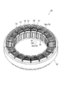
ステータ50は、図6及び図7に示すように環状をなし、その周囲が絶縁性のモールド樹脂21によって被覆されている。なお、モールド樹脂21は、例えばガラス繊維などを含有する熱硬化性樹脂で構成されている。ステータ50の内部には、モールド樹脂21に後輪3側から窪んだ凹部として形成されたロータ収容部51が設けられている。ロータ収容部51は円柱形状をなし、このロータ収容部51内に永久磁石を有するロータ22が配置されている(図2参照)。
モータケース60はアルミ合金などの金属で構成され、ステータ50を被覆したモールド樹脂21を内側に挟んで保持する形で設けられている。モータケース60はモールド樹脂21を内側に挟む形で配置された2個の板状のケース部材、すなわち図3~図5に示す内側ケース61と外側ケース62とで構成されている。図2に示すように、内側ケース61は後輪3側に、外側ケース62は後輪3側と反対側のサスペンションケース10側に各々配置されている。
一方、ステータ50は、図6及び図7に示すように環状をなし、図8に示すステータコア52を備えている。ステータコア52は環状をなすステータヨーク53と、そのステータヨーク53の内周部分から径方向内側に突出するステータティース54とを備えている。ステータティース54はモールドモータ20の周方向に、例えば18個が並べて一周させて配置されている。
図7、図9、及び図10に示すように、ステータティース54先端のロータ22と対向する箇所であるロータ対向面54aには溝部55が設けられている。溝部55はモータ軸線方向に延びてモータ周方向に2本並べて設けられ、モールドモータ20の磁極数とコイル数とのバランスを好適にしてコギングトルクが低減するよう作用している。
ステータティース54の外周には電気絶縁部材であるインシュレータ56が装着されている。さらに、インシュレータ56の外側には電線が巻きつけられてコイル57が形成されている。
また、インシュレータ56は、図7、図10、及び図11に示すようにステータティース54先端のロータ対向面54aの、溝部55のモータ軸線方向両端にリブ部56aを備えている。リブ部56aはインシュレータ56の一部が径方向内側にロータ収容部51に向かって延びる形で構成されている。リブ部56aのロータ収容部51に対向する面はステータティース54のロータ対向面54aと面一になっている。
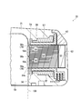
そして、リブ部56aは、ステータ50をモールド樹脂21によって被覆、成型するとき、図10に示すようにロータ収容部51を形成するための金型100(二点鎖線で描画)に、その先端が当接するようになっている。これにより、リブ部56aは溝部55のモータ軸線方向両端から溝部55内にモールド樹脂21が流入するのを阻止する樹脂流入阻止部70となる。そして、この樹脂流入阻止部70はリブ部56aとしてインシュレータ56に一体として構成されるので、別途新たな部材を用意して組み立てる必要がない。
上記実施形態の構成によれば、コギングトルク対策としてステータ50の、ロータ22の永久磁石と対向する箇所に形成した溝部55に対して樹脂流入阻止部70が形成されるので、溝部55にモールド樹脂21が流れ込むのが妨げられる。これにより、モールドモータ20内で飛散し易い溝部55の形状のモールド樹脂小片が成型されるの妨げることができる。
その結果、金型100の高コスト化や成型作業の効率低下を抑制しながら、モールドモータ20の回転不調や破損の原因となるモータ内部におけるモールド樹脂小片の散乱を回避することが可能な、一層信頼性が高められたモールドモータ20を提供することができる。また、このようなモールドモータ20を備えた信頼性の高い電動車両1を提供することが可能である。
次に、本発明の第2の実施形態に係るモールドモータの詳細な構成について、図12を用いて説明する。図12はモールドモータのステータの溝部周辺を示す部分拡大斜視図である。なお、この実施形態の基本的な構成は図1~図11を用いて説明した前記第1の実施形態と同じであるので、第1の実施形態と共通する構成要素には前と同じ符号を付し、図面の記載及びその説明を省略するものとする。
第2の実施形態に係るモールドモータ20において、インシュレータ56のリブ部56aは、図12に示すようにステータティース54のロータ対向面54aから径方向内側に向かって突出している。この構成によれば、リブ部56aの径方向内側に向かって延びるその長さがインシュレータ56の製造上の誤差により比較的短くなってしまっても、リブ部56aは溝部55のモータ軸線方向両端から溝部55内にモールド樹脂21が流入するのを阻止する樹脂流入阻止部70となる。
次に、本発明の第3の実施形態に係るモールドモータの詳細な構成について、図13~図15を用いて説明する。図13はモールドモータのステータの斜視図にして、モールド樹脂による被覆前の状態を示すもの、図14はステータのステータコア周辺の部分拡大垂直断面正面図にして、モールド樹脂による被覆後の状態を示すもの、図15はステータの溝部周辺を示す部分拡大斜視図である。なお、この実施形態の基本的な構成は図1~図11を用いて説明した前記第1の実施形態と同じであるので、第1の実施形態と共通する構成要素には前と同じ符号を付し、図面の記載及びその説明を省略するものとする。
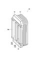
第3の実施形態に係るモールドモータ20において、インシュレータ56は、図13~図15に示すようにステータティース54先端のロータ対向面54aの溝部55に溝部充填部56bを備えている。溝部充填部56bはインシュレータ56の一部が溝部55の内部を充填するように延びて構成されている。インシュレータ56の溝部充填部56bと、そのモータ軸線方向両端の箇所とのロータ収容部51に対向する面はステータティース54のロータ対向面54aと面一になっている。
これにより、インシュレータ56の溝部充填部56bは溝部55内にモールド樹脂21が流入するのを阻止する樹脂流入阻止部70となる。この実施形態の構成によれば、溝部55の内部にモールド樹脂21が流れ込む余地が無くなるので、モールドモータ20内で飛散し易い溝部55の形状のモールド樹脂小片が成型されるの妨げることができる。
次に、本発明の第4の実施形態に係るモールドモータの詳細な構成について、図16を用いて説明する。図16はモールドモータのステータの溝部周辺を示す部分拡大斜視図である。なお、この実施形態の基本的な構成は図1~図11を用いて説明した前記第1の実施形態と同じであるので、第1の実施形態と共通する構成要素には前と同じ符号を付し、図面の記載及びその説明を省略するものとする。
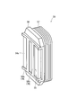
第4の実施形態に係るモールドモータ20において、インシュレータ56の溝部充填部56bは、図16に示すようにステータティース54のロータ対向面54aから径方向内側に向かって突出している。この構成によれば、溝部充填部56bの径方向内側に向かって延びるその長さがインシュレータ56の製造上の誤差により比較的短くなってしまっても、溝部充填部56bは溝部55内にモールド樹脂21が流入するのを阻止する樹脂流入阻止部70となる。
次に、本発明の第5の実施形態に係るモールドモータの詳細な構成について、図17~図21を用いて説明する。図17はモールドモータのステータの斜視図にして、モールド樹脂による被覆前の状態を示すもの、図18はステータのステータコアの平面図、図19はステータティースの構造を示す説明図、図20はステータのステータコア周辺の部分拡大垂直断面正面図にして、モールド樹脂による被覆後の状態を示すもの、図21はステータの溝部周辺を示す部分拡大斜視図である。なお、図19~図21ではステータティースを構成する鋼板の枚数を実際に対して略して描画している。また、この実施形態の基本的な構成は図1~図11を用いて説明した前記第1の実施形態と同じであるので、第1の実施形態と共通する構成要素には前と同じ符号を付し、図面の記載及びその説明を省略するものとする。
第5の実施形態に係るモールドモータ20において、図17に示すステータ50のステータティース54は、図18に示すように隣り合う複数個、例えば2個または4個が一体として構成されている。そして、ステータティース54は、図19~図21に示すように複数枚の鋼板58をモータ軸線方向に積層して形成されている。
鋼板58は連結鋼板58aと、単体鋼板58bとを備えている。連結鋼板58aは、図19に示すように隣り合うステータティース54間で一体として構成されている。単体鋼板58bは単一のステータティース54に対応した形状となっている。そして、図19~図21に示すように、連結鋼板58aはステータティース54のモータ軸線方向両端部及び中央部の3箇所に例えば1枚或いは2枚程度積層して配置され、それら連結鋼板58aの間に単体鋼板58bが例えば20枚程度積層して配置されている。
また、ステータティース54先端のロータ対向面54aの溝部55は単体鋼板58bにのみ設けられている。すなわち、単体鋼板58bに溝部55に対応する断面形状の凹部を設け、ステータティース54を形成すべく単体鋼板58bをモータ軸線方向に積層することによりモータ軸線方向に延びる溝部55が形成される。
そして、複数枚の鋼板58で構成されたステータティース54のロータ対向面54aは、ステータ50をモールド樹脂21によって被覆、成型するとき、図20に示すようにロータ収容部51を形成するための金型100(二点鎖線で描画)に当接するようになっている。これにより、鋼板58のうちの連結鋼板58aが溝部55のモータ軸線方向両端から溝部55内にモールド樹脂21が流入するのを阻止する樹脂流入阻止部70となる。
この実施形態の構成によれば、この樹脂流入阻止部70はステータコア52を形成する鋼板58の一部として構成されるので、別途新たな部材を用意して組み立てる必要がない。また、樹脂流入阻止部70として形成された連結鋼板58aが隣り合うステータティース54間で一体として構成されているので、溝部55にモールド樹脂21が流れ込むのを妨げながらステータコア52の強度アップを図ることができる。
次に、本発明の第6の実施形態に係るモールドモータの詳細な構成について、図22~図25を用いて説明する。図22はモールドモータのステータの斜視図にして、モールド樹脂による被覆前の状態の一部を示すもの、図23はステータの溝部周辺を示す部分拡大斜視図、図24は図22に示すステータの一部の平面図、図25はステータの一部の断面図である。なお、この実施形態の基本的な構成は図1~図11を用いて説明した前記第1の実施形態と同じであるので、第1の実施形態と共通する構成要素には前と同じ符号を付し、図面の記載及びその説明を省略するものとする。
第6の実施形態に係るモールドモータ20においてインシュレータ56は、ステータティース54先端のロータ対向面54aの溝部55のモータ軸線方向両端(図22及び図23における溝部55の上下)に設けられたリブ部56aに加えて、ロータ対向面54aのモータ周方向両端(図22及び図23におけるロータ対向面54aの左右)に設けられたリブ部56cを備えている。リブ部56cは溝部55のモータ軸線方向両端にわたって延びている。すなわち、リブ部56a及び56cは4辺でロータ対向面54a及び溝部55の周りを取り囲む形で設けられている。
なお、リブ部56a及び56cは、図23及び図25に示すようにステータティース54のロータ対向面54aから径方向内側に向かって突出している。また、図22に示すようにリブ部56a及び56cはモータ周方向に環状に複数個並べられたステータティース54各々に対応して個別に設けられている。
ここで、ステータ50の組み立て方法について説明する。図22、図24及び図25に示すように、ステータ50のステータティース54は隣り合う複数個、例えば4個が1つのステータヨーク53の取り付けられることにより一体として構成される。また、環状をなすステータヨーク53(例えば図8参照)を複数に区分したステータヨーク53の1つに4個のステータティース54が取り付けられる。
組み立ての初期段階では未だステータティース54がステータヨーク53に取り付けられていない。そして、4個のステータティース54に対してその外周に個別にインシュレータ56を装着する。インシュレータ56は径方向外側からステータティース54に装着する。なお、インシュレータ56の外側には電線が予め巻きつけられたコイル57が形成されている。
次に、4個のステータティース54のロータ対向面54aが設けられた側の反対側の箇所をステータヨーク53の内周部分に取り付ける。ステータティース54のロータ対向面54aが設けられた側の反対側の箇所には嵌合凸部54bが設けられている。この嵌合凸部54bとステータヨーク53内周部分の対応する箇所に設けられた嵌合凹部53aとを噛み合わせることによりステータティース54とステータヨーク53とが結合される。
このようにして、図22、図24及び図25に示すステータ50の一部が完成する。そして、このステータ50の一部をモータ周方向に沿って複数個並べて結合することによりモールド樹脂21による被覆前の状態のステータ50が完成する(例えば図7参照)。なお、図24及び図25に示すように、ステータヨーク53はモータ周方向に隣り合う他のステータヨーク53と連結するための連結凸部53b及び連結凹部53cを各々個別に備えている(図22では描画を省略)。
そして、リブ部56a及び56cはステータ50をモールド樹脂21によって被覆、成型するとき、ロータ収容部51を形成するための金型100(図22~図25では図示せず、例えば図10に二点鎖線で描画)にその先端が当接するようになっている。これにより、リブ部56a及び56cは溝部55のモータ軸線方向両端から溝部55内に、さらにロータ対向面54aのモータ周方向に沿って溝部55内にモールド樹脂21が流入するのを阻止する樹脂流入阻止部70となる。
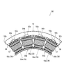
次に、本発明の第7の実施形態に係るモールドモータの詳細な構成について、図26~図29を用いて説明する。図26はモールドモータのステータの斜視図にして、モールド樹脂による被覆前の状態の一部を示すもの、図27は図26に示すステータの一部の平面図、図28はステータの一部の断面図、図29はステータの一部の部分拡大平面図である。なお、この実施形態の基本的な構成は前記第1及び第6の実施形態と同じであるので、これらの実施形態と共通する構成要素には前と同じ符号を付し、図面の記載及びその説明を省略するものとする。
第7の実施形態に係るモールドモータ20においてインシュレータ56は、図26に示すようにステータティース54先端のロータ対向面54aの溝部55のモータ軸線方向両端にリブ部56aを備えている。リブ部56aはインシュレータ56の一部が径方向内側に向かって延び、さらにモータ周方向に沿って延びる形で構成されている。なお、リブ部56aはモータ周方向に環状に複数個並べられたステータティース54各々に対応して個別に設けられている。
図27~図29に示すように、リブ部56aのモータ周方向両端の外縁部には係合部59が設けられている。係合部59は溝部55のモータ軸線方向両端に設けられた2箇所のリブ部56aにわたってモータ軸線方向に沿って延びている。そして、係合部59には隣り合うインシュレータ56の係合部59どうしが係合して連結するように段差が形成されている。係合部59のこの段差は隣り合うインシュレータ56をモータ軸線方向に沿って接近させたときに互いの係合部59どうしが係合可能な形で構成されている。隣り合うインシュレータ56の係合部59どうしはほぼ密着した状態で連結することができる。
ここで、ステータ50の組み立て方法について説明する。なお、ステータ50のステータティース54及びステータヨーク53の構成は前記第6の実施形態と同様である。
組み立ての初期段階では未だステータティース54がステータヨーク53に取り付けられていない。そして、4個のステータティース54に対してその外周に個別にインシュレータ56を装着する。次に、4個のステータティース54のロータ対向面54aが設けられた側の反対側の箇所をステータヨーク53の内周部分に取り付ける。このとき、隣り合うインシュレータ56の係合部59どうしを噛み合わせてモータ周方向に連結した状態にしてステータティース54をステータヨーク53に取り付ける。
このようにして、図26~図28に示すステータ50の一部が完成する。そして、このステータ50の一部をモータ周方向に沿って複数個並べて結合することによりモールド樹脂21による被覆前の状態のステータ50が完成する(例えば図7参照)。なお、このステータ50の一部をモータ周方向に沿って複数個並べて結合する際にも、隣り合うインシュレータ56の係合部59どうしを噛み合わせる。
上記のように、樹脂流入阻止部70であるリブ部56aがモータ周方向に環状に複数個並べられたステータティース54各々に対応して個別に設けられるとともに、隣り合うステータティース54各々に対応して設けられた別の樹脂流入阻止部70である係合部59どうしが連結されている。これにより、モータ周方向に環状に並べられた複数個のステータティース54に対して隣り合うステータティース54の係合部59どうしの隙間がなくなる。したがって、隣り合う係合部59と係合部59との間から溝部55内にモールド樹脂21が流れ込むのを妨げることができる。
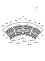
次に、本発明の第8の実施形態に係るモールドモータの詳細な構成について、図30~図32を用いて説明する。図30はモールドモータのステータの斜視図にして、モールド樹脂による被覆前の状態の一部を示すもの、図31はステータの一部の平面図、図32はステータの一部の部分拡大平面図である。なお、この実施形態の基本的な構成は前記第1、第6及び第7の実施形態と同じであるので、これらの実施形態と共通する構成要素には前と同じ符号を付し、図面の記載及びその説明を省略するものとする。
第8の実施形態に係るモールドモータ20においてインシュレータ56は、図30~図32に示すようにステータティース54先端のロータ対向面54aの、溝部55のモータ軸線方向両端にリブ部56aを備えている。リブ部56aはインシュレータ56の一部が径方向内側に向かって延び、さらにモータ周方向に沿って延びる形で構成されている。なお、リブ部56aはモータ周方向に環状に複数個並べられたステータティース54各々に対応して個別に設けられている。
ステータ50のステータティース54は隣り合う複数個、例えば4個が1つのステータヨーク53の取り付けられることにより一体として構成される。そして、4個のインシュレータ56の、隣り合うリブ部56aのモータ周方向両端の外縁部には係合部59が設けられている。一方、モータ周方向に関して外側(図30及び図31において左右両端側)のステータティース54のインシュレータ56の、リブ部56aのモータ周方向外側の外縁部には係合部59が設けられていない(図32参照、なお図32は図30及び図31の右端側のステータティース54を示している)。すなわち、隣り合うインシュレータ56が存在しないロータ対向面54aのモータ周方向外側の箇所ではリブ部56cが溝部55のモータ軸線方向両端にわたって延びている。
上記のような構成によっても、リブ部56a、56c及び係合部59は樹脂流入阻止部70となり、溝部55内にモールド樹脂21が流れ込むのを妨げることができる。
以上、本発明の実施形態につき説明したが、本発明の範囲はこれに限定されるものではなく、発明の主旨を逸脱しない範囲で種々の変更を加えて実施することができる。
例えば、本発明の実施形態では、モールドモータ20を搭載した移動体に、図1に示す電動車両1である自動二輪車を一例として掲げて説明したが、搭載対象となる移動体は自動二輪車に限定されるわけではなく、自動三輪車や自動四輪車であっても構わない。
そして、本発明のバッテリ装置の適用対象となる移動体はモータボート等の船舶や水上遊具といった乗り物、さらにモータを駆動源とし、人が搭乗せず無人で移動する移動体であっても構わない。
本発明は、モールドモータ全般において利用可能である。
1 電動車両(移動体)
20 モールドモータ
21 モールド樹脂
22 ロータ
50 ステータ
51 ロータ収容部
52 ステータコア
54 ステータティース
54a ロータ対向面
55 溝部
56 インシュレータ(電気絶縁部材)
56a、56c リブ部(樹脂流入阻止部)
56b 溝部充填部
57 コイル
58 鋼板
58a 連結鋼板(樹脂流入阻止部)
58b 単体鋼板
59 係合部(樹脂流入阻止部)
70 樹脂流入阻止部
20 モールドモータ
21 モールド樹脂
22 ロータ
50 ステータ
51 ロータ収容部
52 ステータコア
54 ステータティース
54a ロータ対向面
55 溝部
56 インシュレータ(電気絶縁部材)
56a、56c リブ部(樹脂流入阻止部)
56b 溝部充填部
57 コイル
58 鋼板
58a 連結鋼板(樹脂流入阻止部)
58b 単体鋼板
59 係合部(樹脂流入阻止部)
70 樹脂流入阻止部
Claims (9)
- ステータコアとコイルとを有する環状のステータをモールド樹脂によって被覆、成型したモールドモータであって、
前記ステータコアの、前記ステータに対して回転自在に支持されたロータと対向する箇所に設けられたモータ軸線方向に延びる溝部と、
前記溝部への前記モールド樹脂の流入を阻止する樹脂流入阻止部と、
を備えることを特徴とするモールドモータ。 - 前記樹脂流入阻止部は、前記溝部のモータ軸線方向両端に備えられ、前記モールド樹脂の成型のとき、前記ロータを収容するロータ収容部を形成するための型に、その先端が当接することを特徴とする請求項1に記載のモールドモータ。
- 前記樹脂流入阻止部は、前記ステータコアの、前記ロータと対向する箇所のモータ周方向両端に備えられ、前記モールド樹脂の成型のとき、前記ロータを収容するロータ収容部を形成するための型に、その先端が当接することを特徴とする請求項2に記載のモールドモータ。
- 前記ステータコアは、前記溝部が設けられモータ周方向に環状に複数個並べられたステータティースを備え、
前記樹脂流入阻止部は、前記複数のステータティース各々に対応して個別に設けられるとともに、隣り合う前記ステータティース各々に対応して設けられた前記樹脂流入阻止部どうしが連結されていることを特徴とする請求項2または請求項3に記載のモールドモータ。 - 前記ステータコアと前記コイルとの間に電気絶縁部材を備え、
前記樹脂流入阻止部は、前記電気絶縁部材の一部が径方向内側に前記ロータ収容部に向かって延びるリブ部で構成されていることを特徴とする請求項2~請求項4に記載のモールドモータ。 - 前記ステータコアは、少なくともその一部が複数枚の鋼板をモータ軸線方向に積層して形成され、
前記樹脂流入阻止部は、前記溝部を設けていない前記ステータコアを形成する前記鋼板の一部で構成されていることを特徴とする請求項2に記載のモールドモータ。 - 前記ステータコアは、前記溝部が設けられモータ周方向に環状に複数個並べられたステータティースを備え、
前記溝部を設けていない前記鋼板が、隣り合う前記ステータティース間で一体として構成されていることを特徴とする請求項6に記載のモールドモータ。 - 前記ステータコアと前記コイルとの間に電気絶縁部材を備え、
前記樹脂流入阻止部は、前記電気絶縁部材の一部が前記溝部の内部を充填するように延びて構成されていることを特徴とする請求項1に記載のモールドモータ。 - 請求項1~請求項8のいずれか1項に記載のモールドモータを搭載したことを特徴とする移動体。
Priority Applications (1)
| Application Number | Priority Date | Filing Date | Title |
|---|---|---|---|
| JP2012526543A JPWO2012014969A1 (ja) | 2010-07-30 | 2011-07-28 | モールドモータ及びこれを搭載した移動体 |
Applications Claiming Priority (2)
| Application Number | Priority Date | Filing Date | Title |
|---|---|---|---|
| JP2010172397 | 2010-07-30 | ||
| JP2010-172397 | 2010-07-30 |
Publications (1)
| Publication Number | Publication Date |
|---|---|
| WO2012014969A1 true WO2012014969A1 (ja) | 2012-02-02 |
Family
ID=45530169
Family Applications (1)
| Application Number | Title | Priority Date | Filing Date |
|---|---|---|---|
| PCT/JP2011/067235 Ceased WO2012014969A1 (ja) | 2010-07-30 | 2011-07-28 | モールドモータ及びこれを搭載した移動体 |
Country Status (2)
| Country | Link |
|---|---|
| JP (1) | JPWO2012014969A1 (ja) |
| WO (1) | WO2012014969A1 (ja) |
Cited By (4)
| Publication number | Priority date | Publication date | Assignee | Title |
|---|---|---|---|---|
| WO2013046786A1 (ja) * | 2011-09-30 | 2013-04-04 | 三洋電機株式会社 | モールドモータ及びこれを搭載した移動体 |
| US20190252930A1 (en) * | 2018-02-09 | 2019-08-15 | Miba Sinter Austria Gmbh | Stator arrangement for an axial-flow machine |
| WO2022210714A1 (ja) * | 2021-03-31 | 2022-10-06 | ミネベアミツミ株式会社 | モータ |
| EP4009491A4 (en) * | 2020-04-14 | 2022-12-14 | Shanghai Moons' Electric Co., Ltd | INJECTION MOLDED STEPPER MOTOR |
Citations (6)
| Publication number | Priority date | Publication date | Assignee | Title |
|---|---|---|---|---|
| JPS6110962A (ja) * | 1984-06-26 | 1986-01-18 | Sanyo Denki Kk | ステツピングモ−タ |
| JP2000152530A (ja) * | 1998-11-09 | 2000-05-30 | Matsushita Electric Ind Co Ltd | モールドモータ |
| JP2001086682A (ja) * | 1999-09-17 | 2001-03-30 | Sanyo Denki Co Ltd | 回転電機用ステータ |
| JP2002291190A (ja) * | 2001-03-28 | 2002-10-04 | Nippon Densan Corp | モータ |
| JP2007124791A (ja) * | 2005-10-27 | 2007-05-17 | Mitsui High Tec Inc | 積層鉄心及びその製造方法 |
| JP2010104221A (ja) * | 2008-09-26 | 2010-05-06 | Sanyo Electric Co Ltd | 電動モータ及び電動車輌 |
-
2011
- 2011-07-28 JP JP2012526543A patent/JPWO2012014969A1/ja not_active Withdrawn
- 2011-07-28 WO PCT/JP2011/067235 patent/WO2012014969A1/ja not_active Ceased
Patent Citations (6)
| Publication number | Priority date | Publication date | Assignee | Title |
|---|---|---|---|---|
| JPS6110962A (ja) * | 1984-06-26 | 1986-01-18 | Sanyo Denki Kk | ステツピングモ−タ |
| JP2000152530A (ja) * | 1998-11-09 | 2000-05-30 | Matsushita Electric Ind Co Ltd | モールドモータ |
| JP2001086682A (ja) * | 1999-09-17 | 2001-03-30 | Sanyo Denki Co Ltd | 回転電機用ステータ |
| JP2002291190A (ja) * | 2001-03-28 | 2002-10-04 | Nippon Densan Corp | モータ |
| JP2007124791A (ja) * | 2005-10-27 | 2007-05-17 | Mitsui High Tec Inc | 積層鉄心及びその製造方法 |
| JP2010104221A (ja) * | 2008-09-26 | 2010-05-06 | Sanyo Electric Co Ltd | 電動モータ及び電動車輌 |
Cited By (5)
| Publication number | Priority date | Publication date | Assignee | Title |
|---|---|---|---|---|
| WO2013046786A1 (ja) * | 2011-09-30 | 2013-04-04 | 三洋電機株式会社 | モールドモータ及びこれを搭載した移動体 |
| US20190252930A1 (en) * | 2018-02-09 | 2019-08-15 | Miba Sinter Austria Gmbh | Stator arrangement for an axial-flow machine |
| US10886796B2 (en) * | 2018-02-09 | 2021-01-05 | Miba Sinter Austria Gmbh | Stator arrangement for an axial-flow machine |
| EP4009491A4 (en) * | 2020-04-14 | 2022-12-14 | Shanghai Moons' Electric Co., Ltd | INJECTION MOLDED STEPPER MOTOR |
| WO2022210714A1 (ja) * | 2021-03-31 | 2022-10-06 | ミネベアミツミ株式会社 | モータ |
Also Published As
| Publication number | Publication date |
|---|---|
| JPWO2012014969A1 (ja) | 2013-09-12 |
Similar Documents
| Publication | Publication Date | Title |
|---|---|---|
| JP4360305B2 (ja) | インホイールモータのハウジング構造 | |
| JP4842670B2 (ja) | ロータおよび電動車両 | |
| JP7626343B2 (ja) | 人力駆動車用のドライブユニットおよび人力駆動車 | |
| JPWO2019066003A1 (ja) | ロータ、スポーク型モータ、車両用モータ、無人飛行体、電動アシスト装置およびロボット装置 | |
| JPWO2019066004A1 (ja) | ロータ、スポーク型モータ、車両用モータ、無人飛行体、電動アシスト装置およびロボット装置 | |
| JPWO2012014969A1 (ja) | モールドモータ及びこれを搭載した移動体 | |
| JP2020164024A (ja) | 電動車両用モータ | |
| US8217539B2 (en) | Electric motor having an encapsulated stator for a vehicle braking device | |
| JP2021036750A (ja) | 車載モータ及びステアリング装置 | |
| JP2020164114A (ja) | 電動車両用モータ | |
| JP7386078B2 (ja) | 人力駆動車用のドライブユニットおよび人力駆動車用のドライブユニットの製造方法 | |
| US10840762B2 (en) | Brushless motor and electric bicycle provided with the same | |
| JP2011160550A (ja) | 電動モータ、電動車輌及び電動モータの製造方法 | |
| JP5327094B2 (ja) | ブラシレスモータ用ステータ、ブラシレスモータ及び電動パワーステアリング装置 | |
| JP2013166437A (ja) | 車輪駆動装置 | |
| JP2020167835A (ja) | モータ及び車両 | |
| WO2012090679A1 (ja) | モータ及びこれを搭載した電動車両、モータの組み立て方法 | |
| CN105480371A (zh) | 一种驱动电机 | |
| WO2013046786A1 (ja) | モールドモータ及びこれを搭載した移動体 | |
| JP7701787B2 (ja) | 人力駆動車の発電機、発電機の固定子、および固定子の製造方法 | |
| JP2008100642A (ja) | 電動式パワーステアリング装置 | |
| JP2012016265A (ja) | モールドモータ及びこれを搭載した移動体 | |
| JP2011025730A (ja) | 電動車両 | |
| JP2009291015A (ja) | モータ | |
| JP2007221854A (ja) | ステータの固定構造および電動車両 |
Legal Events
| Date | Code | Title | Description |
|---|---|---|---|
| 121 | Ep: the epo has been informed by wipo that ep was designated in this application |
Ref document number: 11812558 Country of ref document: EP Kind code of ref document: A1 |
|
| WWE | Wipo information: entry into national phase |
Ref document number: 2012526543 Country of ref document: JP |
|
| NENP | Non-entry into the national phase |
Ref country code: DE |
|
| 122 | Ep: pct application non-entry in european phase |
Ref document number: 11812558 Country of ref document: EP Kind code of ref document: A1 |