WO2012014919A1 - 光プローブ及び光断層画像化装置 - Google Patents
光プローブ及び光断層画像化装置 Download PDFInfo
- Publication number
- WO2012014919A1 WO2012014919A1 PCT/JP2011/067059 JP2011067059W WO2012014919A1 WO 2012014919 A1 WO2012014919 A1 WO 2012014919A1 JP 2011067059 W JP2011067059 W JP 2011067059W WO 2012014919 A1 WO2012014919 A1 WO 2012014919A1
- Authority
- WO
- WIPO (PCT)
- Prior art keywords
- light
- optical
- lumen
- measurement
- optical fiber
- Prior art date
- Legal status (The legal status is an assumption and is not a legal conclusion. Google has not performed a legal analysis and makes no representation as to the accuracy of the status listed.)
- Ceased
Links
Images


Classifications
-
- A—HUMAN NECESSITIES
- A61—MEDICAL OR VETERINARY SCIENCE; HYGIENE
- A61B—DIAGNOSIS; SURGERY; IDENTIFICATION
- A61B10/00—Instruments for taking body samples for diagnostic purposes; Other methods or instruments for diagnosis, e.g. for vaccination diagnosis, sex determination or ovulation-period determination; Throat striking implements
- A61B10/02—Instruments for taking cell samples or for biopsy
- A61B10/04—Endoscopic instruments, e.g. catheter-type instruments
-
- A—HUMAN NECESSITIES
- A61—MEDICAL OR VETERINARY SCIENCE; HYGIENE
- A61B—DIAGNOSIS; SURGERY; IDENTIFICATION
- A61B5/00—Measuring for diagnostic purposes; Identification of persons
- A61B5/0059—Measuring for diagnostic purposes; Identification of persons using light, e.g. diagnosis by transillumination, diascopy, fluorescence
- A61B5/0062—Arrangements for scanning
- A61B5/0066—Optical coherence imaging
-
- A—HUMAN NECESSITIES
- A61—MEDICAL OR VETERINARY SCIENCE; HYGIENE
- A61B—DIAGNOSIS; SURGERY; IDENTIFICATION
- A61B5/00—Measuring for diagnostic purposes; Identification of persons
- A61B5/0059—Measuring for diagnostic purposes; Identification of persons using light, e.g. diagnosis by transillumination, diascopy, fluorescence
- A61B5/0082—Measuring for diagnostic purposes; Identification of persons using light, e.g. diagnosis by transillumination, diascopy, fluorescence adapted for particular medical purposes
- A61B5/0084—Measuring for diagnostic purposes; Identification of persons using light, e.g. diagnosis by transillumination, diascopy, fluorescence adapted for particular medical purposes for introduction into the body, e.g. by catheters
-
- A—HUMAN NECESSITIES
- A61—MEDICAL OR VETERINARY SCIENCE; HYGIENE
- A61B—DIAGNOSIS; SURGERY; IDENTIFICATION
- A61B1/00—Instruments for performing medical examinations of the interior of cavities or tubes of the body by visual or photographical inspection, e.g. endoscopes; Illuminating arrangements therefor
- A61B1/00163—Optical arrangements
- A61B1/00172—Optical arrangements with means for scanning
-
- A—HUMAN NECESSITIES
- A61—MEDICAL OR VETERINARY SCIENCE; HYGIENE
- A61B—DIAGNOSIS; SURGERY; IDENTIFICATION
- A61B10/00—Instruments for taking body samples for diagnostic purposes; Other methods or instruments for diagnosis, e.g. for vaccination diagnosis, sex determination or ovulation-period determination; Throat striking implements
- A61B10/02—Instruments for taking cell samples or for biopsy
- A61B2010/0216—Sampling brushes
Definitions
- the present invention relates to an optical probe and an optical tomographic imaging apparatus, and more particularly to an optical probe and an optical tomographic imaging apparatus capable of performing biopsy and treatment while observing an optical tomographic image.
- an electronic endoscope apparatus that irradiates illumination light inside the body cavity of a living body, captures an image of reflected light reflected, and displays it on a monitor or the like is widely spread. It is used in various fields.
- many endoscope apparatuses include a forceps port, and a biopsy or treatment of tissue in the body cavity can be performed by a probe introduced into the body cavity via the forceps port.
- OCT optical coherence tomography
- OCT optical coherence tomography
- This OCT measurement is a measurement method that utilizes the fact that interference light is detected when the optical path lengths of the measurement light, reflected light, and reference light coincide. That is, in this method, the low coherent light emitted from the light source is divided into measurement light and reference light, the measurement light is irradiated onto the measurement object, and reflected light from the measurement object is guided to the multiplexing device. On the other hand, the reference light is guided to the multiplexing device after the optical path length is changed in order to change the measurement depth in the measurement target. Then, the reflected light and the reference light are combined by the multiplexer, and the interference light resulting from the combination is measured by heterodyne detection or the like.
- the tomographic image is acquired by changing the measurement position (measurement depth) with respect to the measurement object by changing the optical path length of the reference light.
- This method is generally referred to as TD-OCT (Time domain OCT) measurement.
- an optical tomographic imaging device based on SD-OCT (Spectral Domain OCT) measurement or SS-OCT (Swept source OCT) measurement is proposed as a device for acquiring tomographic images at high speed without changing the optical path length of the reference light.
- SD-OCT Spectral Domain OCT
- SS-OCT Sewept source OCT
- a two-dimensional or three-dimensional optical tomographic image of a predetermined scanning region can be acquired by repeating the measurement while slightly shifting the irradiation position.
- the OCT probe optical probe
- the OCT probe optical probe
- the OCT probe has a smaller diameter than the insertion portion of the endoscope. For this reason, even in regions where the diameter of the lumen such as the bile duct, pancreatic duct, blood vessel, and bronchial end is small and the insertion part of the endoscope cannot be inserted, optical tomographic images can be observed with the OCT probe. It is possible.
- Patent Document 1 proposes an endoscopic treatment instrument that includes a multi-lumen sheath, an OCT probe is inserted into one lumen, and a biopsy brush (cytodiagnosis brush) is inserted into the other lumen. Has been.
- an OCT probe is inserted into a multi-lumen sheath, and an optical fiber or an optical lens is further formed in the sheath (probe outer cylinder) of the OCT probe.
- the sheath probe outer cylinder
- the sheath 1620 of the OCT probe 1600 multi-lumen.
- the first and second lumens 1630 and 1632 are juxtaposed in parallel with each other, and the first lumen 1630 protrudes more in the axial direction than the second lumen 1632.
- the first lumen 1630 is inserted with a probe body including an optical lens 1628 and a rotation-side optical fiber 1650.
- the tip of the first lumen 1630 is closed to prevent entry of body fluid, cleaning fluid, and the like.
- a biopsy brush 1634 is inserted through the second lumen 1632 as a treatment tool.
- An opening 1632 a for leading out the biopsy brush 1634 is formed at the tip of the second lumen 1632.
- the optical lens 1628 and the rotation side optical fiber 1650 are configured to be rotatable in the arrow R2 direction around the axial direction of the rotation side optical fiber 1650. Further, it is configured to be movable in the arrow S1 direction (forceps opening direction) parallel to the axial direction of the rotation-side optical fiber 1650 and the S2 direction (tip direction of the first lumen 1630).
- a flat surface is formed on a part of the outer wall surface of the projecting portion of the first lumen 1630 (the portion projecting toward the distal end side in the axial direction from the second lumen 1632) 1630a.
- the thickness of the outer peripheral wall of the first lumen 1630 is configured to be uneven along the circumferential direction. For this reason, when acquiring the return light from the measurement target while scanning the measurement light irradiated to the measurement target from the optical lens 1628, the influence of refraction of the light passing through the sheath 1620 differs depending on the scanning direction of the measurement light. There is a problem that the image quality of the tomographic image is degraded.
- An object of the present invention is to provide an optical probe and an optical tomographic imaging apparatus capable of performing biopsy and treatment while observing an image.
- an optical probe irradiates a measurement object while rotating and scanning the measurement light propagated from the light source through the optical fiber around the axis of the optical fiber.
- An optical system that receives the return light from the optical fiber and introduces it into the optical fiber; a sheath inserted into the subject; a first lumen in which the tip is closed and the optical system is accommodated; and a tip And a sheath including a second lumen in which a treatment tool for performing biopsy or treatment is accommodated, and the first and second lumens are parallel to each other in the axial direction.
- the first lumen is formed so as to protrude from the tip end side in the axial direction with respect to the second lumen, and the protruding portion protruding from the second lumen of the first lumen is formed in the protruding portion.
- Optical system is arranged Is, the outer wall of the projecting portion is made of a member having optical transparency, and is configured in a cylindrical shape having a uniform wall thickness.
- the influence of refraction of light passing through the sheath does not differ depending on the scanning direction of the measurement light, the detection accuracy of interference light is improved, and a good optical tomographic image can be obtained.
- This makes it possible to perform biopsy or treatment while confirming the position of the lesion site from the optical tomographic image even in a lesion site in a narrow region in the body cavity that cannot be observed by the endoscope.
- the focal length of the optical system is determined according to the diameter of the second lumen, and the optical probe includes the second of the first and second lumens. It is preferable that the lumen side is pressed so as to be the measurement object side.
- the optical probe according to the above aspect is a stopper member provided in the second lumen, the stopper member for restricting the protruding amount of the treatment instrument led out from the opening, and the treatment instrument. It is preferable that a protruding portion of the treatment instrument is regulated by further providing a stopper receiving portion provided and bringing the stopper receiving portion into contact with the stopper member.
- the optical probe according to the above aspect further includes a marker portion provided on the sheath for identifying the direction of the first or second lumen.
- the marker portion is provided on the outer wall of the first lumen on the side opposite to the second lumen.
- the sheath further includes at least one fixing balloon, and when the optical probe is pressed against a measurement target, the fixing balloon is brought into contact with a body cavity wall in the subject.
- the fixing balloon is brought into contact with a body cavity wall in the subject.
- the treatment instrument is preferably a biopsy brush.
- the treatment instrument is preferably a radiation marker or a high-frequency marker.
- the optical system scans the measurement light applied to the measurement object while rotating around the axis of the optical fiber and moving in the axial direction of the optical fiber, It is preferable that the axially movable range of the system is included in the protruding portion.
- the sheath has a structure in which the tips of two tubular members are bonded in parallel while being shifted in the axial direction.
- an optical tomographic imaging apparatus includes a light dividing unit that divides light emitted from a light source into measurement light and reference light, and measures the measurement light.
- An irradiation optical unit that irradiates the target, a multiplexing unit that combines the reference light and the reflected light from the measurement target by the measurement light irradiated by the irradiation optical unit, and the multiplexing unit
- An interference light detection unit that detects interference light between the reflected light and the reference light
- an image acquisition unit that acquires a tomographic image of the measurement target based on the interference light detected by the interference light detection unit.
- the irradiation optical unit includes the optical probe according to the above aspect.
- the influence of refraction of light passing through the sheath does not differ depending on the scanning direction of the measurement light, the detection accuracy of interference light is improved, and a good optical tomographic image can be obtained.
- This makes it possible to perform biopsy or treatment while confirming the position of the lesion site from the optical tomographic image even in a lesion site in a narrow region in the body cavity that cannot be observed by the endoscope.
- FIG. 1 is an external view showing an image diagnostic apparatus using an optical tomographic imaging apparatus according to an embodiment of the present invention.
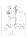
- the block diagram which shows the internal structure of the OCT processor of FIG.
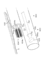
- the perspective view which showed the outline of the front-end
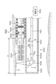
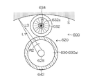
- Front sectional view of the OCT probe in FIG. Front sectional view showing another configuration example of the tip of the OCT probe
- FIG. 1 is an external view showing an image diagnostic apparatus using an optical tomographic imaging apparatus according to an embodiment of the present invention.
- the diagnostic imaging apparatus 10 includes an endoscope 100, an endoscope processor 200, a light source apparatus 300, an optical tomographic imaging apparatus (OCT processor) 400, and a monitor apparatus 500.
- the endoscope processor 200 may incorporate the light source device 300.
- the endoscope 100 includes a hand operation unit 112 and an insertion unit 114 connected to the hand operation unit 112. The surgeon grasps and operates the hand operation unit 112, and performs observation by inserting the insertion unit 114 into the body of the subject.
- a universal cable 116 is connected to the hand operation unit 112, and an LG connector 120 is provided at the tip of the universal cable 116.
- illumination light is sent to the illumination optical system 152 disposed at the distal end portion of the insertion portion 114.
- the LG connector 120 is connected to an electrical connector 110 via a universal cable 116, and the electrical connector 110 is detachably coupled to the endoscope processor 200.
- observation image data obtained by the endoscope 100 is output to the endoscope processor 200 and an image is displayed on the monitor device 500 connected to the endoscope processor 200.
- the hand operating unit 112 is provided with an air / water feed button 126, a suction button 128, a shutter button 130, a function switching button 132, a pair of angle knobs 134, and a pair of lock levers 136. The description about is omitted.
- the hand operation section 112 is provided with a forceps insertion section 138.
- the forceps insertion portion 138 is communicated with the forceps port 156 of the distal end portion 144.
- the OCT probe 600 as an optical probe is inserted from the forceps insertion portion 138, whereby the OCT probe 600 is led out from the forceps port 156.
- the OCT probe 600 is inserted into the OCT processor 400 via the insertion portion 602 inserted from the forceps insertion portion 138 and led out from the forceps opening 156, the operation portion 604 for the operator to operate the OCT probe 600, and the connector 610. It consists of a cable 606 to be connected.
- the insertion portion 114 of the endoscope 100 includes a flexible portion 140, a bending portion 142, and a distal end portion 144 in this order from the hand operating portion 112 side.
- the distal end portion 144 is provided with an observation optical system 150, an illumination optical system 152, an air / water supply nozzle 154, a forceps port 156, and the like. A description of the air / water supply nozzle 154 is omitted.
- the observation optical system 150 is disposed on the distal end surface of the distal end portion 144, and a CCD (charge-coupled device, not shown), which is a solid-state imaging device, is disposed at the back of the observation optical system 150.
- a signal cable (not shown) is connected to the substrate of the CCD, and this signal cable is inserted into the insertion portion 114, the hand operation portion 112, the universal cable 116, etc., and extended to the electrical connector 110, and the endoscope processor 200.
- the observation image captured by the observation optical system 150 is formed on the light receiving surface of the CCD and converted into an electric signal.
- the electric signal is output to the endoscope processor 200 and converted into a video signal. Thereby, an observation image is displayed on the monitor device 500 connected to the endoscope processor 200.
- the illumination optical system 152 is disposed on both sides of the observation optical system 150.
- the number and arrangement of the illumination optical systems 152 are not limited to the embodiment shown in FIG.
- An exit end of a light guide (not shown) is disposed in the back of the illumination optical system 152.
- This light guide is inserted into the insertion portion 114, the hand operating portion 112, and the universal cable 116, and the incident end of the light guide is LG.
- the area is irradiated.
- a forceps channel (not shown) as a tube-like treatment instrument channel is connected to the forceps port 156.
- the forceps channel is inserted into the insertion portion 114 and then branched.
- One of the forceps channels communicates with the forceps insertion portion 138 of the hand operation portion 112 and the other is connected to a suction valve (not shown) in the hand operation portion 112. .
- the suction valve is operated by a suction button 128, whereby a lesioned part or the like can be sucked from the forceps opening 156.
- a curved portion 142 is provided on the proximal end side of the distal end portion 144 configured as described above.
- the bending portion 142 is configured to be bent remotely by rotating the angle knob 134 of the hand operation portion 112.
- a flexible portion 140 is provided on the proximal end side of the curved portion 142.
- the flexible part 140 has flexibility, and is configured, for example, by covering a core material made of a metal net tube with a coating such as a resin.
- FIG. 2 is a block diagram showing an internal configuration of the OCT processor of FIG.
- An OCT processor 400 and an OCT probe 600 shown in FIG. 2 are for obtaining an optical tomographic image of a measurement object by an optical coherence tomography (OCT) measurement method, and emit a light La for measurement.
- One light source unit (first light source unit) 12 and light La emitted from the first light source unit 12 are branched into measurement light (first light beam) L1 and reference light L2, and measurement is performed on the subject.
- An optical fiber coupler (branching / combining unit) 14 that generates the interference light L4 by combining the return light L3 from the target S and the reference light L2, and the measurement light L1 branched by the optical fiber coupler 14 is guided to the measurement target.
- An OCT probe 600 including a rotation-side optical fiber FB1 that waves and guides the return light L3 from the measurement target, and the measurement light L1 as the rotation-side optical fiber
- a fixed-side optical fiber FB2 that guides the return light L3 guided by the rotation-side optical fiber FB1 while being guided to B1, and the rotation-side optical fiber FB1 is rotatably connected to the fixed-side optical fiber FB2,
- the optical connector 18 that transmits the measurement light L1 and the return light L3, the interference light detection unit 20 that detects the interference light L4 generated by the optical fiber coupler 14 as an interference signal, and the interference detected by the interference light detection unit 20 It has a signal processing unit 22 that processes the signal and acquires an optical tomographic image (hereinafter also simply referred to as “tomographic image”). Further, the optical tomographic image acquired by the signal processing unit 22 is displayed on the monitor device 500.
- the OCT processor 400 adjusts the optical path length of the second light source unit (second light source unit) 13 that emits aiming light (second light flux) Le for indicating a mark of measurement, and the reference light L2.
- An optical path length adjustment unit 26 an optical fiber coupler 28 that splits the light La emitted from the first light source unit 12, and detectors 30a and 30b that detect return lights L4 and L5 combined by the optical fiber coupler 14.
- an operation control unit 32 that inputs various conditions to the signal processing unit 22, changes settings, and the like.
- various lights including the above-described emission light La, aiming light Le, measurement light L1, reference light L2, return light L3, etc. are guided between components such as optical devices.
- Various optical fibers FB (FB3, FB4, FB5, FB6, FB7, FB8, etc.) including the rotation side optical fiber FB1 and the fixed side optical fiber FB2 are used as light paths for wave transmission.
- the first light source unit 12 emits light for OCT measurement (for example, laser light having a wavelength of 1.3 ⁇ m or low coherence light), and a light source 12a that emits laser light or low coherence light La; And a lens 12b that condenses the light La emitted from the light source 12a.
- the light La emitted from the first light source unit 12 is divided into the measurement light L1 and the reference light L2 by the optical fiber coupler 14 through the optical fibers FB4 and FB3, and the measurement light L1 is the optical connector. 18 is input.
- the second light source unit 13 emits visible light to make it easy to confirm the measurement site as the aiming light Le.
- red semiconductor laser light having a wavelength of 0.66 ⁇ m, He—Ne laser light having a wavelength of 0.63 ⁇ m, blue semiconductor laser light having a wavelength of 0.405 ⁇ m, or the like can be used. Therefore, the second light source unit 13 includes, for example, a semiconductor laser 13a that emits red, blue, or green laser light, and a lens 13b that condenses the aiming light Le emitted from the semiconductor laser 13a.
- the aiming light Le emitted from the second light source unit 13 is input to the optical connector 18 through the optical fiber FB8.
- the measurement light L1 and the aiming light Le are combined and guided to the rotation side optical fiber FB1 in the OCT probe 600.
- the optical fiber coupler (branching / combining unit) 14 is composed of, for example, a 2 ⁇ 2 optical fiber coupler.
- the optical fiber coupler (branching / multiplexing unit) 14 is optically connected to the fixed-side optical fiber FB2, the optical fiber FB3, the optical fiber FB5, and the optical fiber FB7, respectively.
- the optical fiber coupler 14 divides the light La incident from the first light source unit 12 through the optical fibers FB4 and FB3 into measurement light (first light flux) L1 and reference light L2, and the measurement light L1 is fixed.
- the light is incident on the optical fiber FB2, and the reference light L2 is incident on the optical fiber FB5.
- the optical fiber coupler 14 is incident on the optical fiber FB5, is obtained by the OCT probe 600 described later, and the light L2 that is returned to the optical fiber FB5 after the frequency shift and the optical path length are changed by the optical path length adjusting unit 26 described later. Then, the light L3 guided from the fixed side optical fiber FB2 is multiplexed and emitted to the optical fiber FB3 (FB6) and the optical fiber FB7.
- the OCT probe 600 is connected to the fixed optical fiber FB2 via the optical connector 18, and the measurement light L1 combined with the aiming light Le is rotated from the fixed optical fiber FB2 via the optical connector 18.
- the light enters the side optical fiber FB1.
- the measurement light L1 combined with the incident aiming light Le is transmitted by the rotation side optical fiber FB1 and is irradiated onto the measurement object S.
- the return light L3 from the measuring object S is acquired, the acquired return light L3 is transmitted by the rotation side optical fiber FB1, and is emitted to the fixed side optical fiber FB2 via the optical connector 18. .
- the optical connector 18 multiplexes the measurement light (first light beam) L1 and the aiming light (second light beam) Le.
- the interference light detection unit 20 is connected to the optical fiber FB6 and the optical fiber FB7.
- the interference light detection unit 20 detects interference lights L4 and L5 generated by combining the reference light L2 and the return light L3 by the optical fiber coupler 14 as interference signals.
- the OCT processor 400 is provided on the optical fiber FB6 branched from the optical fiber coupler 28.
- the detector 30a detects the light intensity of the interference light L4, and the light of the interference light L5 on the optical path of the optical fiber FB7. And a detector 30b for detecting the intensity.
- the interference light detector 20 generates an interference signal based on the detection results of the detectors 30a and 30b.
- the signal processing unit 22 is a region where the OCT probe 600 and the measurement target S are in contact at the measurement position, more precisely, a probe outer cylinder (described later) of the OCT probe 600. A region that can be considered to be in contact with the surface of the measuring object S is detected. Further, the signal processing unit 22 acquires a tomographic image from the interference signal detected by the interference light detection unit 20, and outputs the acquired tomographic image to the monitor device 500.
- the optical path length adjusting unit 26 is arranged on the side of the optical fiber FB5 where the reference light L2 is emitted (that is, the end of the optical fiber FB5 opposite to the optical fiber coupler 14).
- the optical path length adjustment unit 26 includes a first optical lens 80 that converts the light emitted from the optical fiber FB5 into parallel light, a second optical lens 82 that condenses the light converted into parallel light by the first optical lens 80, and The reflection mirror 84 that reflects the light collected by the second optical lens 82, the base 86 that supports the second optical lens 82 and the reflection mirror 84, and the base 86 are moved in a direction parallel to the optical axis direction.
- the optical path length of the reference light L2 is adjusted by changing the distance between the first optical lens 80 and the second optical lens 82.
- the first optical lens 80 converts the reference light L2 emitted from the core of the optical fiber FB5 into parallel light, and condenses the reference light L2 reflected by the reflection mirror 84 on the core of the optical fiber FB5.
- the second optical lens 82 condenses the reference light L2 converted into parallel light by the first optical lens 80 on the reflection mirror 84, and makes the reference light L2 reflected by the reflection mirror 84 parallel light.
- the first optical lens 80 and the second optical lens 82 form a confocal optical system.
- the reflection mirror 84 is disposed at the focal point of the light collected by the second optical lens 82 and reflects the reference light L2 collected by the second optical lens 82.
- the reference light L2 emitted from the optical fiber FB5 becomes parallel light by the first optical lens 80, and is condensed on the reflection mirror 84 by the second optical lens 82. Thereafter, the reference light L2 reflected by the reflection mirror 84 becomes parallel light by the second optical lens 82 and is condensed by the first optical lens 80 on the core of the optical fiber FB5.
- the base 86 fixes the second optical lens 82 and the reflecting mirror 84, and the mirror moving mechanism 88 moves the base 86 in the optical axis direction of the first optical lens 80 (the direction of arrow A in FIG. 2). .
- the distance between the first optical lens 80 and the second optical lens 82 can be changed, and the optical path length of the reference light L2 can be adjusted. Can do.
- the operation control unit 32 includes an input device such as a keyboard and a mouse, and a control device that manages various conditions based on the input information, and is connected to the signal processing unit 22.
- the operation control unit 32 inputs, sets, and changes various processing conditions and the like in the signal processing unit 22 based on an operator instruction input from the input device.
- the operation control unit 32 may display the operation screen on the monitor device 500, or may provide a separate display unit to display the operation screen. Further, the operation control unit 32 controls the operation of the first light source unit 12, the second light source unit 13, the optical connector 18, the interference light detection unit 20, the optical path length, the detectors 30a and 30b, and sets various conditions. You may do it.
- FIG. 3 is a perspective view schematically showing the tip of the OCT probe of FIG. 4 is a side sectional view of the OCT probe of FIG. 3 viewed from a direction parallel to the axial direction
- FIG. 5 is a front sectional view of the OCT probe of FIG. 3 viewed from a direction perpendicular to the axial direction. is there.
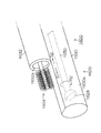
- the distal end portion of the OCT probe 600 includes a multi-lumen type sheath (probe outer tube) 620 having a first lumen 630 and a second lumen 632, and a rotation-side optical fiber FB 1. And an optical lens 628.
- the sheath 620 has a structure in which two flexible tubular members (cylindrical members) are bonded in parallel by shifting the position of the tip in the axial direction, and the first lumen is attached to one tubular member. 630 is formed, and the second lumen 632 is formed on the other tubular member.
- the first and second lumens 630 and 632 are juxtaposed so as to be parallel to each other, and the first lumen 630 has a predetermined tip protrusion amount X (see FIG. 4) closer to the tip end in the axial direction than the second lumen 632. (See)).
- the projecting portion of the first lumen 630 (the portion projecting toward the tip end side in the axial direction from the second lumen 632) 630a is formed in a cylindrical shape, and the wall thickness of the outer peripheral wall is uniform along the circumferential direction and the axial direction. It is configured.
- the sheath 620 is made of a material (light transmissive material) that transmits the measurement light L1 (aiming light Le) and the return light L3. Note that it is not always necessary that the entire sheath 620 is made of a light transmissive material, and at least the outer peripheral wall of the protruding portion 630a of the first lumen 630 may be made of a light transmissive material.
- the first lumen 630 is a probe body insertion channel (pipe) through which probe bodies such as the rotation side optical fiber FB1 and the optical lens 628 are inserted.
- the distal end of the first lumen 630 is configured to be blocked for the purpose of preventing intrusion of body fluid, cleaning liquid, and the like, and is blocked by, for example, a cap (not shown).
- the rotation-side optical fiber FB1 is a linear member and is accommodated in the first lumen 630 along the axial direction of the first lumen 630.
- the rotation-side optical fiber FB1 guides the measurement light L1 (aiming light Le) incident from the fixed-side optical fiber FB2 through the optical connector 18 to the optical lens 628, and from the measurement object S acquired by the optical lens 628. Is returned to the optical connector 18.
- the rotation side optical fiber FB1 and the fixed side optical fiber FB2 are connected by the optical connector 18 as shown in FIG. 2, and the rotation of the rotation side optical fiber FB1 is not transmitted to the fixed side optical fiber FB2. , Optically connected. Further, the rotation-side optical fiber FB1 is arranged so as to be rotatable about its axial direction and movable along the axial direction of the rotation-side optical fiber FB1.
- the optical lens 628 is disposed at the measurement-side tip of the rotation-side optical fiber FB1 (tip of the rotation-side optical fiber FB1 opposite to the optical connector 18).
- the optical lens 628 is formed in a substantially spherical shape for condensing the measuring light L1 (aiming light Le) guided by the rotation side optical fiber FB1 with respect to the measuring object S.
- the optical lens 628 irradiates the measurement object S with the measurement light L1 (aiming light Le) transmitted from the rotation side optical fiber FB1, collects the return light L3 from the measurement object S, and transmits it to the rotation side optical fiber FB1. To do.
- the rotation-side optical fiber FB1 and the optical lens 628 are configured to be rotatable in the direction of the arrow R2 around the axial direction of the rotation-side optical fiber FB1 by the drive unit 640 (see FIG. 4). Further, the rotation side optical fiber FB1 and the optical lens 628 are movable in the arrow S1 direction (forceps opening direction) parallel to the axial direction of the rotation side optical fiber FB1 and the S2 direction (tip direction of the first lumen 630). It is configured.
- the drive part 640 since the structure of the drive part 640 is known, description is abbreviate
- the second lumen 632 is a treatment instrument insertion channel (pipe) through which a treatment instrument for performing a biopsy or treatment is inserted.
- a biopsy brush 634 as a treatment tool is inserted through the second lumen 632.
- the treatment tool inserted through the second lumen 632 is not limited to the biopsy brush 634, and for example, a radiation marker, a high-frequency marker, or the like may be used.
- An opening 632 a is formed at the tip of the second lumen 632.
- the brush portion 634a formed at the tip of the biopsy brush 634 By deriving the brush portion 634a formed at the tip of the biopsy brush 634 through the opening 632a, the biopsy of the measurement target S can be performed while observing the tomographic image by the OCT probe 600.
- the brush portion 634a of the biopsy brush 634 is located inside the opening 632a, that is, in the second lumen 632.
- the biopsy brush 634 is completely accommodated. Further, after the biopsy is completed, the biopsy brush 634 is accommodated in the second lumen 632, so that the tip of the OCT probe 600 is pulled out of the subject as a protective part of the biopsy brush 634. Also works.
- the second lumen 632 is provided with a stopper portion 636 for restricting the protruding amount of the treatment tool such as the biopsy brush 634.
- the stopper portion 636 is formed at a predetermined position on the inner peripheral surface of the second lumen 632 so as to protrude inward over the entire circumferential direction or a part thereof.
- a stopper portion 638 is provided on the shaft portion 634 b of the biopsy brush 634, and the opening portion of the second lumen 632 is brought into contact with the stopper portion 636 of the second lumen 632.
- the protruding amount of the biopsy brush 634 from 632a is regulated. The same applies to the case where a radiation marker, a high-frequency marker, or the like is used as a treatment instrument.
- the second lumen 632 side is not the first lumen 630 side but the measurement target S.
- the focal length f of the optical lens 628 is preferably set according to the diameter of the second lumen 632.
- the optical lens 628 and the measuring object S are not connected to each other. A constant distance according to the diameter of the second lumen 632 is maintained. Therefore, by setting the focal length f of the optical lens 628 according to the diameter of the second lumen 632, the focal point of the optical lens 628 can be easily measured by simply pressing the OCT probe 600 against the measurement target S. S can be matched. Thereby, the detection accuracy of the return light L3 from the measuring object S can be improved.
- the sheath 620 is preferably provided with a probe orientation detection marker 642 for detecting the orientation of the OCT probe 600.
- a linear probe orientation detection marker 642 extending in the axial direction is formed at a position 180 degrees opposite to the second lumen 632 in the outer peripheral wall of the first lumen 630.
- the probe orientation detection marker 642 is formed on the outer side of the outer peripheral wall of the first lumen 630.
- the present invention is not limited to this, and may be formed on the inner side of the outer peripheral wall of the first lumen 630.
- the OCT probe 600 is inserted from the forceps insertion portion 138 provided in the hand operation portion 112 of the endoscope 100, and the OCT probe 600 is led out from the forceps port 156. Then, the tip of the OCT probe 600 led out from the forceps port 156 of the endoscope 100 is pressed against the measurement object S. At that time, not the first lumen 630 side but the second lumen 632 side faces the measuring object S.
- the OCT probe 600 uses the drive unit 640 to rotate the rotation-side optical fiber FB1 and the optical lens 628 in the direction of the arrow R2, so that the measurement light L1 (aiming light Le) emitted from the optical lens 628 becomes the measurement target S.
- the measurement light L1 aiming light Le
- irradiation is performed while scanning in the direction of the arrow R2, and the return light L3 from the measurement target S is acquired.
- the aiming light Le is applied to the measuring object S as, for example, blue, red, or green spot light.
- the reflected light of the aiming light Le is also displayed as a bright spot on the observation image displayed on the monitor device 500.
- the desired part of the measuring object S can be accurately captured on the entire circumference of the first lumen 630 in the circumferential direction, and the return light L3 reflected from the measuring object S can be acquired.
- the optical lens 628 is moved by the drive unit 640 to the end of the movable range in the arrow S1 direction (point A in FIG. 3), While acquiring the image, it moves in the S2 direction by a predetermined amount.
- the optical lens 628 moves to the end of the movable range (point B in FIG. 3) while alternately repeating tomographic image acquisition and a predetermined amount of movement in the S2 direction.
- the movable range of the optical lens 628 (the range from the point A to the point B in FIG. 3) is included in the protrusion 630 a of the first lumen 630.
- a plurality of tomographic images in a desired range can be obtained for the measurement object S, and three-dimensional volume data can be obtained based on the acquired plurality of tomographic images.
- the brush portion 634a of the biopsy brush 634 is derived from the opening 632a of the second lumen 632, and the position of the brush portion 634a is determined. While confirming the tomographic image displayed on the monitor device 500, the image is brought closer to the measuring object S. And the structure
- the biopsy brush 634 is accommodated in the second lumen 632. Thereby, it is possible to protect the tissue attached to the surface of the biopsy brush 634 until the tip of the OCT probe 600 is pulled out of the subject.
- the movable range of the optical lens 628 (the range from the point A to the point B in FIG. 4) is the front end side of the protruding portion of the first lumen 630 (the second lumen 632).
- the protruding portion is configured to be included in 630a.
- the outer peripheral wall of the protruding portion 630a of the first lumen 630 is configured in a cylindrical shape, and the thickness thereof is configured uniformly along the circumferential direction and the axial direction.
- FIG. 6 is a front sectional view showing another configuration example of the tip of the OCT probe.
- a cross section corresponding to the base end side from the cross section shown in FIG. 5 is shown.
- the first to third fixing balloons 644A, 644B, and 644C are provided on the outer peripheral surface of the first lumen 630 (the outer surface of the outer peripheral wall) at the distal end portion of the OCT probe 600 shown in FIG. Specifically, the outer peripheral surface of the second lumen 632 is disposed on the outer peripheral surface of the first lumen 630 on the proximal end side with respect to the protruding portion (the portion protruding toward the distal end side in the axial direction from the second lumen 632).
- the fixing balloons 644A to 644C are arranged while shifting the phase by 90 degrees starting from the position where the (outer surface of the outer peripheral wall) is connected.
- gas supply conduits communicating with the respective fixing balloons 644A to 644C are provided, and each of the fixing balloons 644A to 644C is provided with a gas supply tube. It is configured to be freely expandable and contractible by gas supplied or sucked through the passage.
- the present invention is not limited to this.
- one or two fixing balloons may be arranged, The above fixing balloons may be arranged.
- the fixing balloons 644A to 644C are expanded from the contracted state to the expanded state.
- the surface of each of the fixing balloons 644A to 644C is brought into contact with the body cavity wall of the subject.
- the SS-OCT (Swept Source OCT) device has been described as the OCT processor 400.
- the present invention is not limited to this, and the OCT processor 400 can also be applied as an SD-OCT (Spectral Domain OCT) device. It is.
- DESCRIPTION OF SYMBOLS 10 ... Diagnostic imaging apparatus, 22 ... Signal processing part, 100 ... Endoscope, 156 ... Forceps opening, 200 ... Endoscope processor, 300 ... Light source apparatus, 400 ... OCT processor, 500 ... Monitor apparatus, 600 ... OCT probe, 620 ... sheath, 630 ... first lumen, 632 ... second lumen, 634 ... biopsy brush, 636 ... stopper member, 638 ... stopper receiving portion, 640 ... driving portion, 644A, 644B, 644C ... balloon for fixation
Landscapes
- Health & Medical Sciences (AREA)
- Life Sciences & Earth Sciences (AREA)
- Surgery (AREA)
- Heart & Thoracic Surgery (AREA)
- Molecular Biology (AREA)
- Veterinary Medicine (AREA)
- Engineering & Computer Science (AREA)
- Biomedical Technology (AREA)
- Public Health (AREA)
- Medical Informatics (AREA)
- Pathology (AREA)
- Animal Behavior & Ethology (AREA)
- General Health & Medical Sciences (AREA)
- Nuclear Medicine, Radiotherapy & Molecular Imaging (AREA)
- Radiology & Medical Imaging (AREA)
- Physics & Mathematics (AREA)
- Biophysics (AREA)
- Endoscopes (AREA)
- Investigating Or Analysing Materials By Optical Means (AREA)
Abstract
本発明の一態様に係る光プローブ600は、光源から光ファイバを通して伝搬した測定光を該光ファイバの軸線周りに回転走査しながら測定対象に照射するとともに、該測定対象からの戻り光を受けて前記光ファイバに導入する光学系628と、被検体内に挿入されるシース620であって、先端部が閉塞され、前記光学系が収容される第1のルーメン630と、先端部に開口部が形成され、生検又は治療を行うための処置具が収容される第2のルーメン632とを備えるシースとを備え、前記第1及び第2のルーメンが互いの軸方向が平行となるように並設されるとともに、前記第1のルーメンが前記第2のルーメンよりも軸方向先端側に突出して形成され、前記第1のルーメンの前記第2のルーメンよりも突出した突出部に前記光学系が配設され、該突出部の外壁は、光透過性を有する部材からなり、且つ、均一な肉厚を有する円筒状に構成される。
Description
本発明は光プローブ及び光断層画像化装置に係り、特に、光断層画像を観察しながら、生検や治療を行うことが可能な光プローブ及び光断層画像化装置に関する。
従来、生体の体腔内を観察する内視鏡装置として、生体の体腔内で照明光を照射し、反射された反射光による像を撮像し、モニタ等に表示する電子内視鏡装置が広く普及し、様々な分野で利用されている。また、多くの内視鏡装置は、鉗子口を備え、この鉗子口を介して体腔内に導入されたプローブにより、体腔内の組織の生検や治療を行うことが可能となっている。
一方、近年、生体組織等の測定対象を切断せずに生体などの断層画像を取得する断層画像取得装置の開発が進められており、例えば、低コヒーレンス光による干渉を用いた光干渉断層(OCT:Optical Coherence Tomography)計測法を利用した光断層画像化装置が知られている。
このOCT計測は、測定光及び反射光と参照光との光路長が一致したときに干渉光が検出されることを利用した計測方法である。すなわち、この方法において、光源から射出された低コヒーレント光は測定光と参照光とに分割され、測定光は測定対象に照射され、測定対象からの反射光が合波装置に導かれる。一方、参照光は、測定対象内の測定深さを変更するために、光路長の変更が施された後に合波装置に導かれる。そして、合波装置により反射光と参照光とが合波され、合波されたことによる干渉光がヘテロダイン検波等により測定される。
上記OCT装置においては、参照光の光路長を変更することにより、測定対象に対する測定位置(測定深さ)を変更し断層画像を取得するようになっている。この手法は、一般にTD-OCT(Time domain OCT)計測と称されている。
他方、参照光の光路長の変更を行うことなく高速に断層画像を取得する装置として、SD-OCT(Spectral Domain OCT)計測あるいはSS-OCT(Swept source OCT)計測による光断層画像化装置が提案されている。
上述した断層画像においては、照射位置を僅かにずらしながら、測定を繰り返すことにより、所定の走査領域の2次元的あるいは3次元的な光断層画像を取得することができる。
OCTプローブ(光プローブ)は、内視鏡装置の処置具チャンネルに挿通されるため、内視鏡の挿入部よりも径が小さく構成されている。このため、胆管、膵管、血管、気管支末端などの管腔内の径が小さく、内視鏡の挿入部を挿入させることができないような領域であっても、OCTプローブによる光断層画像の観察を可能としている。
このため、OCTプローブを用いて、内視鏡により観察することができない体腔内の狭い領域における病変部位であっても、光断層画像から病変部位の位置を確認しつつ、生検や治療を行うようにできることが要望されている。
例えば、特許文献1では、マルチルーメン化されたシースを備え、一方のルーメンにOCTプローブが挿通され、他方のルーメンに生検ブラシ(細胞診ブラシ)が挿通された内視鏡用処置具が提案されている。
しかしながら、特許文献1に開示される内視鏡用処置具では、マルチルーメン化されたシース内にOCTプローブが挿通され、さらにOCTプローブのシース(プローブ外筒)内に光ファイバや光学レンズからなるプローブ本体が挿通されるといった多重構造となっており、細径化には限界がある。
そこで、更なる細径化を図るべく、例えば、図7に示すように、OCTプローブ1600のシース1620をマルチルーメン化することが考えられる。同図に示した構成では、第1及び第2のルーメン1630、1632は互いに平行となるように並設されており、第1のルーメン1630は第2のルーメン1632よりも軸方向先端側に突出して形成される。第1のルーメン1630には、光学レンズ1628及び回転側光ファイバ1650からなるプローブ本体が挿通される。第1のルーメン1630の先端は、体液や洗浄液などの侵入を防ぐために塞がれている。第2のルーメン1632には、処置具として生検ブラシ1634が挿通される。第2のルーメン1632の先端は、生検ブラシ1634を導出するための開口部1632aが形成されている。
光学レンズ1628及び回転側光ファイバ1650は、回転側光ファイバ1650の軸方向を中心として矢印R2方向に回転可能に構成される。更に、回転側光ファイバ1650の軸方向に平行な矢印S1方向(鉗子口方向)、及びS2方向(第1のルーメン1630の先端方向)に移動可能に構成されている。
しかしながら、図7に示した構成では、第1のルーメン1630の突出部(第2のルーメン1632よりも軸方向先端側に突出した部分)1630aの外壁面の一部に平坦面が形成されており、第1のルーメン1630の外周壁の肉厚が周方向に沿って不均一に構成される。このため、光学レンズ1628から測定対象に照射される測定光を走査しながら測定対象からの戻り光を取得する際、測定光の走査方向によってシース1620を通過する光の屈折の影響が異なり、光断層画像の画質が低下してしまうといった問題がある。
本発明は、このような事情に鑑みてなされたもので、測定光の走査方向によってシースを通過する光の屈折の影響が異なることなく、良好な光断層画像を得ることができるとともに、光断層画像を観察しながら生検や治療を行うことができる光プローブ及び光断層画像化装置を提供することを目的とする。
前記目的を達成するために、本発明の一態様に係る光プローブは、光源から光ファイバを通して伝搬した測定光を該光ファイバの軸線周りに回転走査しながら測定対象に照射するとともに、該測定対象からの戻り光を受けて前記光ファイバに導入する光学系と、被検体内に挿入されるシースであって、先端部が閉塞され、前記光学系が収容される第1のルーメンと、先端部に開口部が形成され、生検又は治療を行うための処置具が収容される第2のルーメンとを備えるシースとを備え、前記第1及び第2のルーメンが互いの軸方向が平行となるように並設されるとともに、前記第1のルーメンが前記第2のルーメンよりも軸方向先端側に突出して形成され、前記第1のルーメンの前記第2のルーメンよりも突出した突出部に前記光学系が配設され、該突出部の外壁は、光透過性を有する部材からなり、且つ、均一な肉厚を有する円筒状に構成される。
上記の態様によれば、測定光の走査方向によってシースを通過する光の屈折の影響が異なることがなく、干渉光の検出精度が向上し、良好な光断層画像を得ることができる。これにより、内視鏡により観察することができない体腔内の狭い領域における病変部位であっても、光断層画像から病変部位の位置を確認しつつ、生検や治療を行うことが可能となる。
上記の態様に係る光プローブにおいては、前記光学系の焦点距離は、前記第2のルーメンの径に応じて決定され、前記光プローブは、前記第1及び第2のルーメンのうち、前記第2のルーメン側が測定対象側となるように押し当てられることが好ましい。
上記の態様に係る光プローブは、前記第2のルーメンに設けられたストッパ部材であって、前記開口部から導出される前記処置具の突出量を規制するためのストッパ部材と、前記処置具に設けられるストッパ受け部とを更に備え、前記ストッパ受け部を前記ストッパ部材に当接させることにより、前記処置具の突出量が規制されることが好ましい。
上記の態様に係る光プローブは、前記シースに設けられたマーカ部であって、第1又は第2のルーメンの向きを識別するためのマーカ部を更に備えることが好ましい。
上記の態様に係る光プローブにおいては、前記マーカ部は、前記第2のルーメンとは反対側の第1のルーメンの外壁に設けられていることが好ましい。
上記の態様に係る光プローブは、前記シースは、少なくとも1つの固定用バルーンを更に備え、前記光プローブを測定対象に押し当てた際、前記固定用バルーンを被検体内の体腔壁に当接させることにより前記光プローブを固定することが好ましい。
上記の態様に係る光プローブにおいては、前記処置具は、生検ブラシであることが好ましい。
上記の態様に係る光プローブにおいては、前記処置具は、放射線マーカ又は高周波マーカであることが好ましい。
上記の態様に係る光プローブにおいては、前記光学系は、前記光ファイバの軸線周りに回転しつつ該光ファイバの軸線方向に移動しながら前記測定対象に照射される測定光を走査し、前記光学系の前記軸線方向の移動可能範囲は、前記突出部に含まれることが好ましい。
上記の態様に係る光プローブにおいては、前記シースは、2つのチューブ状部材の先端を軸方向にずらして平行に貼り合わせた構造を有することが好ましい。
また、前記目的を達成するために、本発明の一態様に係る光断層画像化装置は、光源から射出された光を測定光と参照光とに分割する光分割部と、前記測定光を測定対象に照射する照射光学部と、前記照射光学部により照射された前記測定光による前記測定対象からの反射光と前記参照光とを合波する合波部と、前記合波部により合波された前記反射光と前記参照光との干渉光を検出する干渉光検出部と、前記干渉光検出部により検出された前記干渉光に基づいて前記測定対象の断層画像を取得する画像取得部とを備え、前記照射光学部は、上記の態様に係る光プローブを含む。
本発明によれば、測定光の走査方向によってシースを通過する光の屈折の影響が異なることがなく、干渉光の検出精度が向上し、良好な光断層画像を得ることができる。これにより、内視鏡により観察することができない体腔内の狭い領域における病変部位であっても、光断層画像から病変部位の位置を確認しつつ、生検や治療を行うことが可能となる。
以下、添付図面に従って本発明の好ましい実施の形態について詳説する。
図1は、本発明の一実施形態に係る光断層画像化装置を用いた画像診断装置を示す外観図である。
図1に示すように、画像診断装置10は、内視鏡100、内視鏡プロセッサ200、光源装置300、光断層画像化装置(OCTプロセッサ)400、及びモニタ装置500を含んでいる。なお、内視鏡プロセッサ200は、光源装置300を内蔵していてもよい。
内視鏡100は、手元操作部112と、この手元操作部112に連設される挿入部114とを備える。術者は、手元操作部112を把持して操作し、挿入部114を被検者の体内に挿入することによって観察を行う。
手元操作部112には、ユニバーサルケーブル116が接続され、ユニバーサルケーブル116の先端にLGコネクタ120が設けられる。このLGコネクタ120を光源装置300に着脱自在に連結することによって、挿入部114の先端部に配設された照明光学系152に照明光が送られる。また、LGコネクタ120には、ユニバーサルケーブル116を介して電気コネクタ110が接続され、電気コネクタ110が内視鏡プロセッサ200に着脱自在に連結される。これにより、内視鏡100で得られた観察画像のデータが内視鏡プロセッサ200に出力され、内視鏡プロセッサ200に接続されたモニタ装置500に画像が表示される。
また、手元操作部112には、送気・送水ボタン126、吸引ボタン128、シャッターボタン130、機能切替ボタン132、一対のアングルノブ134、一対のロックレバー136が設けられているが、これらの部材についての説明は省略する。
手元操作部112には、鉗子挿入部138が設けられている。この鉗子挿入部138は、先端部144の鉗子口156に連通されている。本実施形態では、光プローブとしてのOCTプローブ600を鉗子挿入部138から挿入することによって、OCTプローブ600を鉗子口156から導出する。OCTプローブ600は、鉗子挿入部138から挿入され、鉗子口156から導出される挿入部602と、術者がOCTプローブ600を操作するための操作部604、及びコネクタ610を介してOCTプロセッサ400と接続されるケーブル606から構成されている。
一方、内視鏡100の挿入部114は、手元操作部112側から順に、軟性部140、湾曲部142、先端部144で構成されている。先端部144には、観察光学系150、照明光学系152、送気・送水ノズル154、鉗子口156等が設けられる。なお、送気・送水ノズル154についての説明は省略する。
観察光学系150は、先端部144の先端面に配設されており、この観察光学系150の奥に固体撮像素子であるCCD(charge-coupled device,不図示)が配設される。CCDの基板には、信号ケーブル(不図示)が接続され、この信号ケーブルが挿入部114、手元操作部112、ユニバーサルケーブル116等に挿通されて電気コネクタ110まで延設され、内視鏡プロセッサ200に接続される。したがって、観察光学系150で取り込まれた観察像はCCDの受光面に結像されて電気信号に変換され、この電気信号が内視鏡プロセッサ200に出力され、映像信号に変換される。これにより、内視鏡プロセッサ200に接続されたモニタ装置500に観察画像が表示される。
照明光学系152は、観察光学系150の両側に配置される。なお、照明光学系152の数及び配置は図1の実施形態に限定されるものではない。照明光学系152の奥には、ライトガイド(不図示)の出射端が配設され、このライトガイドが挿入部114、手元操作部112、ユニバーサルケーブル116に挿通され、ライトガイドの入射端がLGコネクタ120内に配置される。したがって、LGコネクタ120を光源装置300に連結することによって、光源装置300から照射された照明光がライトガイドを介して照明光学系152に伝送され、照明光学系152から先端部144の前方の観察範囲に照射される。
鉗子口156には、チューブ状の処置具チャンネルとしての鉗子チャンネル(不図示)が接続される。鉗子チャンネルは挿入部114の内部に挿通された後、分岐され、一方が手元操作部112の鉗子挿入部138に連通され、他方が手元操作部112内の吸引バルブ(不図示)に接続される。吸引バルブは、吸引ボタン128によって操作され、これによって鉗子口156から病変部等を吸引することができる。
上記の如く構成された先端部144の基端側には湾曲部142が設けられる。湾曲部142は、手元操作部112のアングルノブ134を回動することによって遠隔的に湾曲するように構成される。
湾曲部142の基端側には軟性部140が設けられる。軟性部140は、可撓性を有しており、例えば、金属製の網管から成る心材に、樹脂などの被覆を被せることによって構成される。
なお、内視鏡、内視鏡プロセッサ、及び光源装置の内部構成は公知であるので説明は省略する。
図2は、図1のOCTプロセッサの内部構成を示すブロック図である。
図2に示すOCTプロセッサ400及びOCTプローブ600は、光干渉断層(OCT:Optical Coherence Tomography)計測法による測定対象の光断層画像を取得するためのもので、測定のための光Laを射出する第1の光源部(第1の光源ユニット)12と、第1の光源部12から射出された光Laを測定光(第1の光束)L1と参照光L2に分岐するとともに、被検体である測定対象Sからの戻り光L3と参照光L2を合波して干渉光L4を生成する光ファイバカプラ(分岐合波部)14と、光ファイバカプラ14で分岐された測定光L1を測定対象まで導波するとともに測定対象からの戻り光L3を導波する回転側光ファイバFB1を備えるOCTプローブ600と、測定光L1を回転側光ファイバFB1まで導波するとともに回転側光ファイバFB1によって導波された戻り光L3を導波する固定側光ファイバFB2と、回転側光ファイバFB1を固定側光ファイバFB2に対して回転可能に接続し、測定光L1及び戻り光L3を伝送する光コネクタ18と、光ファイバカプラ14で生成された干渉光L4を干渉信号として検出する干渉光検出部20と、この干渉光検出部20によって検出された干渉信号を処理して光断層画像(以下、単に「断層画像」とも言う。)を取得する信号処理部22を有する。また、信号処理部22で取得された光断層画像はモニタ装置500に表示される。
また、OCTプロセッサ400は、測定の目印を示すためのエイミング光(第2の光束)Leを射出する第2の光源部(第2の光源ユニット)13と、参照光L2の光路長を調整する光路長調整部26と、第1の光源部12から射出された光Laを分光する光ファイバカプラ28と、光ファイバカプラ14で合波された戻り光L4及びL5を検出する検出器30a及び30bと、信号処理部22への各種条件の入力、設定の変更等を行う操作制御部32とを有する。
なお、図2に示すOCTプロセッサ400においては、上述した射出光La、エイミング光Le、測定光L1、参照光L2及び戻り光L3などを含む種々の光を各光デバイスなどの構成要素間で導波し、伝送するための光の経路として、回転側光ファイバFB1及び固定側光ファイバFB2を含め種々の光ファイバFB(FB3、FB4、FB5、FB6、FB7、FB8など)が用いられている。
第1の光源部12は、OCTの測定のための光(例えば、波長1.3μmのレーザ光あるいは低コヒーレンス光)を射出するものであり、レーザ光あるいは低コヒーレンス光Laを射出する光源12aと、光源12aから射出された光Laを集光するレンズ12bとを備えている。詳しくは後述するが、第1の光源部12から射出された光Laは、光ファイバFB4、FB3を介して光ファイバカプラ14で測定光L1と参照光L2に分割され、測定光L1は光コネクタ18に入力される。
また、第2の光源部13は、エイミング光Leとして測定部位を確認しやすくするために可視光を射出するものである。例えば、波長0.66μmの赤半導体レーザ光、波長0.63μmのHe-Neレーザ光、波長0.405μmの青半導体レーザ光などを用いることができる。そこで、第2の光源部13としては、例えば、赤色あるいは青色あるいは緑色のレーザ光を射出する半導体レーザ13aと、半導体レーザ13aから射出されたエイミング光Leを集光するレンズ13bを備えている。第2の光源部13から射出されたエイミング光Leは、光ファイバFB8を介して光コネクタ18に入力される。
光コネクタ18では、測定光L1とエイミング光Leとが合波され、OCTプローブ600内の回転側光ファイバFB1に導波される。
光ファイバカプラ(分岐合波部)14は、例えば、2×2の光ファイバカプラで構成されている。光ファイバカプラ(分岐合波部)14は、固定側光ファイバFB2、光ファイバFB3、光ファイバFB5、光ファイバFB7とそれぞれ光学的に接続されている。
光ファイバカプラ14は、第1の光源部12から光ファイバFB4及びFB3を介して入射した光Laを測定光(第1の光束)L1と参照光L2とに分割し、測定光L1を固定側光ファイバFB2に入射させ、参照光L2を光ファイバFB5に入射させる。
さらに、光ファイバカプラ14は、光ファイバFB5に入射され後述する光路長調整部26によって周波数シフト及び光路長の変更が施されて光ファイバFB5を戻った光L2と、後述するOCTプローブ600で取得され固定側光ファイバFB2から導波された光L3とを合波し、光ファイバFB3(FB6)及び光ファイバFB7に射出する。
OCTプローブ600は、光コネクタ18を介して、固定側光ファイバFB2と接続されており、固定側光ファイバFB2から、光コネクタ18を介して、エイミング光Leと合波された測定光L1が回転側光ファイバFB1に入射される。入射されたこのエイミング光Leと合波された測定光L1は、回転側光ファイバFB1によって伝送されて測定対象Sに照射される。そして、測定対象Sからの戻り光L3を取得し、取得した戻り光L3を回転側光ファイバFB1によって伝送して、光コネクタ18を介して、固定側光ファイバFB2に射出するようになっている。
光コネクタ18は、測定光(第1の光束)L1とエイミング光(第2の光束)Leとを合波するものである。
干渉光検出部20は、光ファイバFB6及び光ファイバFB7と接続されている。干渉光検出部20は、光ファイバカプラ14で参照光L2と戻り光L3とを合波して生成された干渉光L4及びL5を干渉信号として検出する。
ここで、OCTプロセッサ400は、光ファイバカプラ28から分岐させた光ファイバFB6上に設けられ、干渉光L4の光強度を検出する検出器30aと、光ファイバFB7の光路上に干渉光L5の光強度を検出する検出器30bとを有している。
干渉光検出部20は、検出器30a及び検出器30bの検出結果に基づいて、干渉信号を生成する。
信号処理部22は、干渉光検出部20で抽出した干渉信号から、測定位置におけるOCTプローブ600と測定対象Sとの接触している領域、より正確にはOCTプローブ600のプローブ外筒(後述)の表面と測定対象Sの表面とが接触しているとみなせる領域を検出する。さらに、信号処理部22は、干渉光検出部20で検出した干渉信号から断層画像を取得し、取得した断層画像をモニタ装置500へ出力する。
光路長調整部26は、光ファイバFB5の参照光L2の射出側(すなわち、光ファイバFB5の光ファイバカプラ14とは反対側の端部)に配置されている。
光路長調整部26は、光ファイバFB5から射出された光を平行光にする第1光学レンズ80と、第1光学レンズ80で平行光にされた光を集光する第2光学レンズ82と、第2光学レンズ82で集光された光を反射する反射ミラー84と、第2光学レンズ82及び反射ミラー84を支持する基台86と、基台86を光軸方向に平行な方向に移動させるミラー移動機構88とを有し、第1光学レンズ80と第2光学レンズ82との距離を変化させることで参照光L2の光路長を調整する。
第1光学レンズ80は、光ファイバFB5のコアから射出された参照光L2を平行光にするとともに、反射ミラー84で反射された参照光L2を光ファイバFB5のコアに集光する。
また、第2光学レンズ82は、第1光学レンズ80により平行光にされた参照光L2を反射ミラー84上に集光するとともに、反射ミラー84により反射された参照光L2を平行光にする。このように、第1光学レンズ80と第2光学レンズ82とにより共焦点光学系が形成されている。
さらに、反射ミラー84は、第2光学レンズ82で集光される光の焦点に配置されており、第2光学レンズ82で集光された参照光L2を反射する。
これにより、光ファイバFB5から射出した参照光L2は、第1光学レンズ80により平行光になり、第2光学レンズ82により反射ミラー84上に集光される。その後、反射ミラー84により反射された参照光L2は、第2光学レンズ82により平行光になり、第1光学レンズ80により光ファイバFB5のコアに集光される。
また、基台86は、第2光学レンズ82と反射ミラー84とを固定し、ミラー移動機構88は、基台86を第1光学レンズ80の光軸方向(図2矢印A方向)に移動させる。
ミラー移動機構88で、基台86を矢印A方向に移動させることで、第1光学レンズ80と第2光学レンズ82との距離を変更することができ、参照光L2の光路長を調整することができる。
操作制御部32は、キーボード、マウス等の入力装置と、入力された情報に基づいて各種条件を管理する制御装置とを有し、信号処理部22に接続されている。操作制御部32は、上記入力装置から入力されたオペレータの指示に基づいて、信号処理部22における各種処理条件等の入力、設定、変更等を行う。
なお、操作制御部32は、操作画面をモニタ装置500に表示させてもよいし、別途表示部を設けて操作画面を表示させてもよい。また、操作制御部32で、第1の光源部12、第2の光源部13、光コネクタ18、干渉光検出部20、光路長ならびに検出器30a及び30bの動作制御や各種条件の設定を行うようにしてもよい。
次に、本実施形態のOCTプローブ600について説明する。
図3は、図2のOCTプローブの先端部の概略を示した斜視図である。また、図4は、図3のOCTプローブを軸方向に平行な方向から見た側面断面図であり、図5は、図3のOCTプローブを軸方向に垂直な方向から見た正面断面図である。
図3乃至図5に示すように、OCTプローブ600の先端部は、第1のルーメン630及び第2のルーメン632を有するマルチルーメンタイプのシース(プローブ外筒)620と、回転側光ファイバFB1と、光学レンズ628とを備えている。
シース620は、可撓性を有する2つのチューブ状部材(円筒部材)を先端部の位置を軸方向にずらして平行に貼り合わせた構造となっており、一方のチューブ状部材に第1のルーメン630が形成され、他方のチューブ状部材に第2のルーメン632が形成される。
第1及び第2のルーメン630、632は互いに平行となるように並設されるとともに、第1のルーメン630は第2のルーメン632よりも軸方向先端側に所定の先端突出量X(図4参照)だけ突出した構成となっている。この第1のルーメン630の突出部(第2のルーメン632よりも軸方向先端側に突出した部分)630aは円筒状に構成され、その外周壁の肉厚は周方向及び軸方向に沿って均一に構成されている。
シース620は、測定光L1(エイミング光Le)及び戻り光L3を透過する材料(光透過性材料)により構成される。なお、シース620の全体が光透過性材料で構成されることは必ずしも必要ではなく、少なくとも第1のルーメン630の突出部630aの外周壁が光透過性材料で構成されていればよい。
第1のルーメン630は、回転側光ファイバFB1や光学レンズ628などのプローブ本体が挿通されるプローブ本体挿通チャンネル(管路)である。第1のルーメン630の先端は、体液や洗浄液などの侵入を防ぐ目的で塞がれた構成となっており、例えば、キャップ(不図示)などで閉塞されている。
回転側光ファイバFB1は、線状部材であり、第1のルーメン630の内部に、第1のルーメン630の軸方向に沿って収容されている。回転側光ファイバFB1は、固定側光ファイバFB2から光コネクタ18を介して入射された測定光L1(エイミング光Le)を光学レンズ628まで導波するとともに、光学レンズ628で取得した測定対象Sからの戻り光L3を光コネクタ18まで導波する。
ここで、回転側光ファイバFB1と固定側光ファイバFB2とは、図2に示すように光コネクタ18によって接続されており、回転側光ファイバFB1の回転が固定側光ファイバFB2に伝達しない状態で、光学的に接続されている。また、回転側光ファイバFB1は、その軸方向を中心にして回転自在、及び回転側光ファイバFB1の軸方向に沿って移動自在な状態で配置されている。
光学レンズ628は、回転側光ファイバFB1の測定側先端(光コネクタ18と反対側の回転側光ファイバFB1の先端)に配置されている。光学レンズ628は、回転側光ファイバFB1により導波された測定光L1(エイミング光Le)を測定対象Sに対し集光するために略球状の形状で形成されている。
光学レンズ628は、回転側光ファイバFB1から伝達された測定光L1(エイミング光Le)を測定対象Sに対し照射し、測定対象Sからの戻り光L3を集光し回転側光ファイバFB1に伝達する。
回転側光ファイバFB1及び光学レンズ628は、駆動部640(図4参照)により、回転側光ファイバFB1の軸方向を中心として矢印R2方向に回転可能に構成される。さらに、回転側光ファイバFB1及び光学レンズ628は、回転側光ファイバFB1の軸方向に平行な矢印S1方向(鉗子口方向)、及びS2方向(第1のルーメン630の先端方向)に移動可能に構成されている。なお、駆動部640の構成については周知であるので、ここでは説明を省略する。
第2のルーメン632は、生検や治療を行うための処置具が挿通される処置具挿通チャンネル(管路)である。ここでは、一例として、処置具としての生検ブラシ634が第2のルーメン632に挿通されている。なお、第2のルーメン632に挿通される処置具としては、生検ブラシ634に限定されず、例えば、放射線マーカや高周波マーカなどが用いられてもよい。
第2のルーメン632の先端には開口部632aが形成されている。開口部632aを介して生検ブラシ634の先端に形成されるブラシ部634aを導出することにより、OCTプローブ600による断層画像を観察しながら、測定対象Sに対する生検を行うことができる。一方、生検を行う必要がない場合(すなわち、断層画像の観察のみが行われる場合)には、生検ブラシ634のブラシ部634aを開口部632aよりも内側、つまり、第2のルーメン632内に生検ブラシ634が完全に収容された状態にする。また、生検終了後、生検ブラシ634を第2のルーメン632内に収容することにより、被検体の外部にOCTプローブ600の先端部が引き出されるまでの間、生検ブラシ634の保護部としても機能する。
第2のルーメン632には、生検ブラシ634などの処置具の突出量を規制するためのストッパ部636が設けられている。ストッパ部636は、第2のルーメン632の内周面の所定位置に周方向全体又はその一部にわたって内側に突出するようにして形成される。生検ブラシ634の軸部634bにはストッパ受け部638が設けられており、該ストッパ受け部638を第2のルーメン632のストッパ部636に当接させることにより、第2のルーメン632の開口部632aからの生検ブラシ634の突出量が規制されるようになっている。処置具として放射線マーカや高周波マーカなどが用いられる場合についても同様である。
本実施形態では、内視鏡100の鉗子口156から導出されたOCTプローブ600の先端部を測定対象Sに押し当てる際、第1のルーメン630側ではなく、第2のルーメン632側が測定対象Sに向き合うようにする。このとき、光学レンズ628の焦点距離fは、第2のルーメン632の径に応じて設定されていることが好ましい。
第1のルーメン630側ではなく、第2のルーメン632側が測定対象Sに向き合うようにOCTプローブ600の先端を測定対象Sに押し当てることにより、光学レンズ628と測定対象Sとの間には第2のルーメン632の径に応じた一定距離が保たれる。このため、光学レンズ628の焦点距離fを第2のルーメン632の径に応じて設定しておくことにより、OCTプローブ600を測定対象Sに押し当てるだけで光学レンズ628の焦点を容易に測定対象Sに一致させることができる。これにより、測定対象Sからの戻り光L3の検出精度を向上させることができる。
また、シース620には、OCTプローブ600の向きを検出するためのプローブ向き検出用マーカ642が設けられていることが好ましい。具体的には、第1のルーメン630の外周壁のうち第2のルーメン632とは180度反対側の位置に軸方向に延在した直線状のプローブ向き検出用マーカ642を形成する。本例では、プローブ向き検出用マーカ642を第1のルーメン630の外周壁の外側に形成しているが、これに限らず、第1のルーメン630の外周壁の内側に形成してもよい。これにより、OCTプローブ600の先端を測定対象Sに押し当てる際、術者は、断層画像中に現れたプローブ向き検出用マーカ642を確認することにより、OCTプローブ600の向きを容易に識別することが可能となる。
次に、本実施形態のOCTプローブ600の作用について説明する。
まず、内視鏡100の手元操作部112に設けられた鉗子挿入部138からOCTプローブ600を挿入し、OCTプローブ600を鉗子口156から導出する。そして、内視鏡100の鉗子口156から導出されたOCTプローブ600の先端を測定対象Sに押し当てる。その際、第1のルーメン630側ではなく、第2のルーメン632側が測定対象Sに向き合うようにする。
OCTプローブ600は、駆動部640により、回転側光ファイバFB1及び光学レンズ628が矢印R2方向に回転されることで、光学レンズ628から射出される測定光L1(エイミング光Le)を測定対象Sに対し、矢印R2方向に走査しながら照射し、測定対象Sからの戻り光L3を取得する。エイミング光Leは、測定対象Sに、例えば、青色、赤色あるいは緑色のスポット光として照射される。このエイミング光Leの反射光は、モニタ装置500に表示された観察画像に輝点としても表示される。
これにより、第1のルーメン630の円周方向の全周において、測定対象Sの所望の部位を正確にとらえることができ、測定対象Sを反射した戻り光L3を取得することができる。
さらに、3次元ボリュームデータを生成するための複数の断層画像を取得する場合は、駆動部640により光学レンズ628が矢印S1方向の移動可能範囲の終端(図3のA点)まで移動され、断層画像を取得しながら所定量ずつS2方向に移動する。あるいは、光学レンズ628は、断層画像取得とS2方向への所定量移動を交互に繰り返しながら、移動可能範囲の終端(図3のB点)まで移動する。なお、光学レンズ628の移動可能範囲(図3のA点からB点までの範囲)は、第1のルーメン630の突出部630aに含まれるようになっている。
このように測定対象Sに対して所望の範囲の複数の断層画像を得て、取得した複数の断層画像に基づいて3次元ボリュームデータを得ることができる。
また、生検ブラシ634を用いて測定対象Sの生検を行う場合には、第2のルーメン632の開口部632aから生検ブラシ634のブラシ部634aを導出して、ブラシ部634aの位置をモニタ装置500に表示された断層画像を確認しながら測定対象Sに近づける。そして、生検ブラシ634のブラシ部634aで測定対象Sの表面を擦過することにより、測定対象Sの組織が採取される。
このようにして生検が終了した後は、生検ブラシ634は第2のルーメン632内に収容される。これにより、OCTプローブ600の先端部が被検体の外部に引き出されるまでの間、生検ブラシ634の表面に付着した組織を保護しておくことが可能となっている。
本実施形態のOCTプローブ600では、光学レンズ628の移動可能範囲(図4のA点からB点までの範囲)は、第1のルーメン630の突出部(第2のルーメン632よりも先端側に突出した部分)630aに含まれるように構成される。さらに、第1のルーメン630の突出部630aにおける外周壁は円筒状に構成され、その肉厚は周方向及び軸方向に沿って均一に構成される。このため、光学レンズ628から測定対象Sに照射される測定光L1を走査しながら測定対象Sからの戻り光L3を取得する際、測定光L1の走査方向によってシース620を通過する光の屈折の影響(度合い)が異なることがなく、干渉光の検出精度が向上し、良好な断層画像を得ることが可能となる。これにより、内視鏡により観察することができない体腔内の狭い領域における病変部位であっても、光断層画像から病変部位の位置を確認しつつ、生検や治療を行うことが可能となる。
図6は、OCTプローブの先端部の他の構成例を示した正面断面図である。なお、同図では、図5に示した断面よりも基端側に相当する断面を示している。図6中、図5と共通する部材には同一の符号を付して説明を省略する。
図6に示したOCTプローブ600の先端部には、第1のルーメン630の外周面(外周壁の外面)に第1~第3の固定用バルーン644A、644B、644Cが設けられている。具体的には、第1のルーメン630の突出部(第2のルーメン632よりも軸方向先端側に突出した部分)630aよりも基端側の外周面には、第2のルーメン632の外周面(外周壁の外面)が接続される位置を起点として90度ずつ位相をずらしながら各固定用バルーン644A~644Cが配置されている。図示は省略するが、第1のルーメン630の内部には、各固定用バルーン644A~644Cにそれぞれ連通する気体供給用管路が設けられており、各固定用バルーン644A~644Cは気体供給用管路を通じて供給又は吸引される気体によって膨張収縮自在に構成されている。ここでは、好ましい態様として3つの固定用バルーン644A~644Cが配置された構成を示したが、これに限らず、例えば、1つ又は2つの固定用バルーンが配置されていてもよいし、4つ以上の固定用バルーンが配置されていてもよい。
図6に示した構成によれば、内視鏡100の鉗子口156から導出されたOCTプローブ600の先端部を測定対象Sに押し当てる際、各固定用バルーン644A~644Cを収縮状態から膨張状態に変化させて、各固定用バルーン644A~644Cの表面を被検体の体腔壁に当接させる。これにより、OCTプローブ600の先端部は所望の位置で固定されるので、安定した状態でOCTプローブ600により良好な断層画像を取得することが可能となる。
なお、上述した実施形態では、OCTプロセッサ400としてSS-OCT(Swept Source OCT)装置を用いて説明したが、これに限らず、OCTプロセッサ400をSD-OCT(Spectral Domain OCT)装置としても適用可能である。
以上、本発明の光プローブ及び光断層画像化装置について詳細に説明したが、本発明は、以上の例には限定されず、本発明の要旨を逸脱しない範囲において、各種の改良や変形を行ってもよいのはもちろんである。
10…画像診断装置、22…信号処理部、100…内視鏡、156…鉗子口、200…内視鏡プロセッサ、300…光源装置、400…OCTプロセッサ、500…モニタ装置、600…OCTプローブ、620…シース、630…第1のルーメン、632…第2のルーメン、634…生検ブラシ、636…ストッパ部材、638…ストッパ受け部、640…駆動部、644A、644B、644C…固定用バルーン
Claims (11)
- 光プローブであって、
光源から光ファイバを通して伝搬した測定光を該光ファイバの軸線周りに回転走査しながら測定対象に照射するとともに、該測定対象からの戻り光を受けて前記光ファイバに導入する光学系と、
被検体内に挿入されるシースであって、先端部が閉塞され、前記光学系が収容される第1のルーメンと、先端部に開口部が形成され、生検又は治療を行うための処置具が収容される第2のルーメンとを備えるシースとを備え、
前記第1及び第2のルーメンが互いの軸方向が平行となるように並設されるとともに、前記第1のルーメンが前記第2のルーメンよりも軸方向先端側に突出して形成され、
前記第1のルーメンの前記第2のルーメンよりも突出した突出部に前記光学系が配設され、
該突出部の外壁は、光透過性を有する部材からなり、且つ、均一な肉厚を有する円筒状に構成される、光プローブ。 - 前記光学系の焦点距離は、前記第2のルーメンの径に応じて決定され、
前記光プローブは、前記第1及び第2のルーメンのうち、前記第2のルーメン側が測定対象側となるように押し当てられる、請求項1に記載の光プローブ。 - 前記第2のルーメンに設けられたストッパ部材であって、前記開口部から導出される前記処置具の突出量を規制するためのストッパ部材と、
前記処置具に設けられるストッパ受け部とを更に備え、
前記ストッパ受け部を前記ストッパ部材に当接させることにより、前記処置具の突出量が規制される、請求項1又は2に記載の光プローブ。 - 前記シースに設けられたマーカ部であって、第1又は第2のルーメンの向きを識別するためのマーカ部を更に備える請求項1乃至3のいずれか1項に記載の光プローブ。
- 前記マーカ部は、前記第2のルーメンとは反対側の第1のルーメンの外壁に設けられている、請求項4に記載の光プローブ。
- 前記シースは、少なくとも1つの固定用バルーンを更に備え、
前記光プローブを測定対象に押し当てた際、前記固定用バルーンを被検体内の体腔壁に当接させることにより前記光プローブを固定する、請求項1乃至5のいずれか1項に記載の光プローブ。 - 前記処置具は、生検ブラシである、請求項1乃至6のいずれか1項に記載の光プローブ。
- 前記処置具は、放射線マーカ又は高周波マーカである、請求項1乃至6のいずれか1項に記載の光プローブ。
- 前記光学系は、前記光ファイバの軸線周りに回転しつつ該光ファイバの軸線方向に移動しながら前記測定対象に照射される測定光を走査し、
前記光学系の前記軸線方向の移動可能範囲は、前記突出部に含まれる、請求項1乃至8のいずれか1項に記載の光プローブ。 - 前記シースは、2つのチューブ状部材の先端を軸方向にずらして平行に貼り合わせた構造を有する、請求項1乃至9のいずれか1項に記載の光プローブ。
- 光源から射出された光を測定光と参照光とに分割する光分割部と、
前記測定光を測定対象に照射する照射光学部と、
前記照射光学部により照射された前記測定光による前記測定対象からの反射光と前記参照光とを合波する合波部と、
前記合波部により合波された前記反射光と前記参照光との干渉光を検出する干渉光検出部と、
前記干渉光検出部により検出された前記干渉光に基づいて前記測定対象の断層画像を取得する画像取得部とを備え、
前記照射光学部は、請求項1乃至10のいずれか1項に記載の光プローブを含む、光断層画像化装置。
Applications Claiming Priority (2)
| Application Number | Priority Date | Filing Date | Title |
|---|---|---|---|
| JP2010-172681 | 2010-07-30 | ||
| JP2010172681A JP2012029912A (ja) | 2010-07-30 | 2010-07-30 | 光プローブ及び光断層画像化装置 |
Publications (1)
| Publication Number | Publication Date |
|---|---|
| WO2012014919A1 true WO2012014919A1 (ja) | 2012-02-02 |
Family
ID=45530123
Family Applications (1)
| Application Number | Title | Priority Date | Filing Date |
|---|---|---|---|
| PCT/JP2011/067059 Ceased WO2012014919A1 (ja) | 2010-07-30 | 2011-07-27 | 光プローブ及び光断層画像化装置 |
Country Status (2)
| Country | Link |
|---|---|
| JP (1) | JP2012029912A (ja) |
| WO (1) | WO2012014919A1 (ja) |
Cited By (1)
| Publication number | Priority date | Publication date | Assignee | Title |
|---|---|---|---|---|
| CN106691384A (zh) * | 2016-12-29 | 2017-05-24 | 天津恒宇医疗科技有限公司 | 一种减少造影剂用量的oct成像导管 |
Families Citing this family (4)
| Publication number | Priority date | Publication date | Assignee | Title |
|---|---|---|---|---|
| RU2582521C2 (ru) | 2012-02-14 | 2016-04-27 | Бриджстоун Корпорейшн | Шина |
| CN105411509B (zh) * | 2014-09-02 | 2017-11-10 | 乐普(北京)医疗器械股份有限公司 | Oct内窥成像探头及其制造方法和oct成像导管 |
| JP7686632B2 (ja) * | 2019-09-25 | 2025-06-02 | キン エフ. チャン, | 撮像カテーテル、撮像システム、およびその動作の方法 |
| KR102787852B1 (ko) * | 2023-03-28 | 2025-03-28 | 한국광기술원 | 열교환기 배관 삽입형 회전 광스캐닝 기반 배관 내부 표면 검사장치 |
Citations (8)
| Publication number | Priority date | Publication date | Assignee | Title |
|---|---|---|---|---|
| JP2001070229A (ja) * | 1999-07-02 | 2001-03-21 | Asahi Optical Co Ltd | 内視鏡装置 |
| JP2002005822A (ja) * | 2000-06-21 | 2002-01-09 | Olympus Optical Co Ltd | 光プローブ装置 |
| JP2005211127A (ja) * | 2004-01-27 | 2005-08-11 | Olympus Corp | 内視鏡処置システム |
| JP2007075403A (ja) * | 2005-09-15 | 2007-03-29 | Pentax Corp | Oct観察器具、固定器具、及び、octシステム |
| JP2008200098A (ja) * | 2007-02-16 | 2008-09-04 | Hoya Corp | 内視鏡用処置具及び当該処置具を用いたシステム |
| JP2009250630A (ja) * | 2008-04-01 | 2009-10-29 | Fujifilm Corp | 光断層画像取得装置および方法 |
| WO2009137704A1 (en) * | 2008-05-07 | 2009-11-12 | Volcano Corporation | Optical imaging catheter for aberration balancing |
| JP2010142422A (ja) * | 2008-12-18 | 2010-07-01 | Fujifilm Corp | 光プローブ及び光観察装置 |
-
2010
- 2010-07-30 JP JP2010172681A patent/JP2012029912A/ja active Pending
-
2011
- 2011-07-27 WO PCT/JP2011/067059 patent/WO2012014919A1/ja not_active Ceased
Patent Citations (8)
| Publication number | Priority date | Publication date | Assignee | Title |
|---|---|---|---|---|
| JP2001070229A (ja) * | 1999-07-02 | 2001-03-21 | Asahi Optical Co Ltd | 内視鏡装置 |
| JP2002005822A (ja) * | 2000-06-21 | 2002-01-09 | Olympus Optical Co Ltd | 光プローブ装置 |
| JP2005211127A (ja) * | 2004-01-27 | 2005-08-11 | Olympus Corp | 内視鏡処置システム |
| JP2007075403A (ja) * | 2005-09-15 | 2007-03-29 | Pentax Corp | Oct観察器具、固定器具、及び、octシステム |
| JP2008200098A (ja) * | 2007-02-16 | 2008-09-04 | Hoya Corp | 内視鏡用処置具及び当該処置具を用いたシステム |
| JP2009250630A (ja) * | 2008-04-01 | 2009-10-29 | Fujifilm Corp | 光断層画像取得装置および方法 |
| WO2009137704A1 (en) * | 2008-05-07 | 2009-11-12 | Volcano Corporation | Optical imaging catheter for aberration balancing |
| JP2010142422A (ja) * | 2008-12-18 | 2010-07-01 | Fujifilm Corp | 光プローブ及び光観察装置 |
Cited By (1)
| Publication number | Priority date | Publication date | Assignee | Title |
|---|---|---|---|---|
| CN106691384A (zh) * | 2016-12-29 | 2017-05-24 | 天津恒宇医疗科技有限公司 | 一种减少造影剂用量的oct成像导管 |
Also Published As
| Publication number | Publication date |
|---|---|
| JP2012029912A (ja) | 2012-02-16 |
Similar Documents
| Publication | Publication Date | Title |
|---|---|---|
| JP3869589B2 (ja) | ファイババンドル及び内視鏡装置 | |
| JP5118867B2 (ja) | 内視鏡観察装置および内視鏡の作動方法 | |
| US8666209B2 (en) | Delivering light via optical waveguide and multi-view optical probe head | |
| US7324211B2 (en) | Optical tomographic image obtaining apparatus | |
| US8911357B2 (en) | Optical structure observation apparatus and structure information processing method of the same | |
| US20110077463A1 (en) | Optical probe and endoscope apparatus | |
| US20100069747A1 (en) | Diagnostic imaging apparatus | |
| JP2002113017A (ja) | レーザ治療装置 | |
| JP2006204431A (ja) | 蛍光断層画像取得装置 | |
| WO2010071057A1 (ja) | 光プローブ及び光観察装置 | |
| JP2010043994A (ja) | 光プローブ及び3次元画像取得装置 | |
| JP5939746B2 (ja) | 光断層測定用プローブ | |
| WO2012014919A1 (ja) | 光プローブ及び光断層画像化装置 | |
| JP5429447B2 (ja) | 光断層画像測定装置 | |
| JP2010167029A (ja) | 光断層画像取得装置 | |
| JP2008200283A (ja) | 光プローブおよび光断層画像取得装置 | |
| JP2010051390A (ja) | 光断層画像取得装置及び光断層画像取得方法 | |
| JP2011072401A (ja) | 光プローブ及び内視鏡装置 | |
| JP2006026015A (ja) | 光断層画像取得システム | |
| JP2013223635A (ja) | プローブ | |
| JP2011062301A (ja) | 光構造像観察装置、その構造情報処理方法及び光構造像観察装置を備えた内視鏡装置 | |
| JP2010125272A (ja) | 光プローブ、光断層画像化装置 | |
| JP2012085805A (ja) | 光断層画像化装置 | |
| JP2009244233A (ja) | プローブおよび光断層画像取得装置 | |
| JP2014008378A (ja) | プローブ及び内視鏡システム |
Legal Events
| Date | Code | Title | Description |
|---|---|---|---|
| 121 | Ep: the epo has been informed by wipo that ep was designated in this application |
Ref document number: 11812508 Country of ref document: EP Kind code of ref document: A1 |
|
| NENP | Non-entry into the national phase |
Ref country code: DE |
|
| 122 | Ep: pct application non-entry in european phase |
Ref document number: 11812508 Country of ref document: EP Kind code of ref document: A1 |