WO2012011203A1 - 半導体基板熱処理装置 - Google Patents
半導体基板熱処理装置 Download PDFInfo
- Publication number
- WO2012011203A1 WO2012011203A1 PCT/JP2010/067103 JP2010067103W WO2012011203A1 WO 2012011203 A1 WO2012011203 A1 WO 2012011203A1 JP 2010067103 W JP2010067103 W JP 2010067103W WO 2012011203 A1 WO2012011203 A1 WO 2012011203A1
- Authority
- WO
- WIPO (PCT)
- Prior art keywords
- heating coil
- auxiliary
- susceptors
- susceptor
- heat treatment
- Prior art date
- Legal status (The legal status is an assumption and is not a legal conclusion. Google has not performed a legal analysis and makes no representation as to the accuracy of the status listed.)
- Ceased
Links
Images



Classifications
-
- H—ELECTRICITY
- H10—SEMICONDUCTOR DEVICES; ELECTRIC SOLID-STATE DEVICES NOT OTHERWISE PROVIDED FOR
- H10P—GENERIC PROCESSES OR APPARATUS FOR THE MANUFACTURE OR TREATMENT OF DEVICES COVERED BY CLASS H10
- H10P72/00—Handling or holding of wafers, substrates or devices during manufacture or treatment thereof
- H10P72/04—Apparatus for manufacture or treatment
- H10P72/0431—Apparatus for thermal treatment
- H10P72/0434—Apparatus for thermal treatment mainly by convection
-
- H—ELECTRICITY
- H10—SEMICONDUCTOR DEVICES; ELECTRIC SOLID-STATE DEVICES NOT OTHERWISE PROVIDED FOR
- H10P—GENERIC PROCESSES OR APPARATUS FOR THE MANUFACTURE OR TREATMENT OF DEVICES COVERED BY CLASS H10
- H10P95/00—Generic processes or apparatus for manufacture or treatments not covered by the other groups of this subclass
- H10P95/90—Thermal treatments, e.g. annealing or sintering
-
- Y—GENERAL TAGGING OF NEW TECHNOLOGICAL DEVELOPMENTS; GENERAL TAGGING OF CROSS-SECTIONAL TECHNOLOGIES SPANNING OVER SEVERAL SECTIONS OF THE IPC; TECHNICAL SUBJECTS COVERED BY FORMER USPC CROSS-REFERENCE ART COLLECTIONS [XRACs] AND DIGESTS
- Y02—TECHNOLOGIES OR APPLICATIONS FOR MITIGATION OR ADAPTATION AGAINST CLIMATE CHANGE
- Y02P—CLIMATE CHANGE MITIGATION TECHNOLOGIES IN THE PRODUCTION OR PROCESSING OF GOODS
- Y02P10/00—Technologies related to metal processing
- Y02P10/25—Process efficiency
Definitions
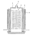
- the heat treatment apparatus disclosed in Patent Document 1 is a batch-type heat treatment apparatus, in which wafers 2 stacked in multiple stages are placed in a quartz process tube 3, and graphite or the like is placed on the outer periphery of the process tube 3.
- the heating tower 4 formed of the conductive member is disposed, and the solenoid-like induction heating coil 5 is disposed on the outer periphery thereof.
- the heating tower 4 is heated by the influence of the magnetic flux generated by the induction heating coil 5, and the wafer 2 disposed in the process tube 3 is heated by the radiant heat from the heating tower 4.
- the heat treatment apparatus disclosed in Patent Document 2 is a single-wafer type heat treatment apparatus, in which a susceptor 7 divided into concentric circles is formed of graphite or the like, and the upper surface of the susceptor 7 is formed.
- a wafer 8 is placed on the side, and a plurality of annular induction heating coils 9 are arranged concentrically on the lower surface side to enable individual power control for the plurality of induction heating coils 9.
- the heat treatment apparatus 6 having such a configuration since heat transfer between the susceptor 7 positioned in the heating range by each induction heating coil 9 and the other susceptor 7 is suppressed, power control for the induction heating coil 9 is performed. This improves the temperature distribution controllability of the wafer 8.
- the magnetic flux acts perpendicularly to the graphite. For this reason, when a metal film or the like is formed on the surface of the wafer as an object to be heated, the wafer may be directly heated, and temperature distribution control may be disturbed.
- each of the main heating coil and the auxiliary heating coil has a rectangular cross-sectional shape of the coil winding region, and a vertical length of the winding region in the main heating coil.
- the length of the auxiliary heating coil may be longer than the vertical length of the winding region.
- auxiliary susceptors are arranged above and below the plurality of susceptors to be processed.
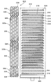
- FIG. 1A and 1B are diagrams showing a configuration of a heat treatment apparatus according to the first embodiment.
- FIG. 1A is a partial cross-sectional block diagram showing a side configuration
- FIG. 1B is a block diagram showing a plan configuration.
- FIG. 2 is a partial cross-sectional block diagram showing a side configuration of the heat treatment apparatus according to the second embodiment.
- FIG. 3 is a block diagram showing a planar configuration of a heat treatment apparatus according to the third embodiment.
- FIG. 4 is a view showing a form in which the main heating coil is divided into a plurality of parts to cope with an increase in the number of susceptors to be processed.
- FIG. 5 is a diagram showing the configuration of a conventional batch induction heating apparatus.
- FIG. 6 is a diagram showing a configuration of a conventional single wafer induction heating apparatus.
- the processing object susceptor 14 and the auxiliary susceptor 16 can be formed of the same material and in the same shape (in the present embodiment, a disk shape). Specifically, it may be made of a conductive member, and may be made of, for example, graphite, SiC, SiC-coated graphite, refractory metal, or the like.
- the boat 12 configured as described above is mounted on a rotary table 20 including a motor (not shown), and can rotate the susceptor (processing target susceptor 14 and auxiliary susceptor 16) and the wafer 18 during the heat treatment process. .
- a rotary table 20 including a motor (not shown), and can rotate the susceptor (processing target susceptor 14 and auxiliary susceptor 16) and the wafer 18 during the heat treatment process.
- the susceptor processing target susceptor 14 and auxiliary susceptor 16
- the wafer 18 during the heat treatment process.
- the induction heating coil according to the present embodiment is configured by winding the coil base material 28 around the cores 30, 32, 34 arranged on the outer peripheral side of the boat 12.
- the induction heating coil according to the present embodiment includes a main heating coil 22 in which the processing object susceptor 14 is disposed as a main heating object, and auxiliary heating coils 24 and 26 in which the auxiliary susceptor 16 is disposed as a main heating object.
- the main heating coil 22 has a vertical winding range set so as to cover the arrangement range of the plurality of processing target susceptors 14 arranged in a stacked manner.
- the auxiliary heating coils 24 and 26 have a vertical winding range so as to cover the arrangement range of the auxiliary susceptor 16.
- the cores 30, 32, and 34 may be made of ferrite ceramics or the like, and may be formed by firing after forming a clay-like raw material. This is because it is possible to freely form a shape by using such a member. Further, by using the cores 30, 32, and 34, the diffusion of magnetic flux can be prevented as compared with the case where the induction heating coil is formed of the coil base material 28 alone, and highly efficient induction heating with concentrated magnetic flux can be performed. Can be realized.
- the main heating coil 22 and the auxiliary heating coils 24, 26 are wound around the outer periphery of the cores 30, 32, 34 with the end faces facing the center of the susceptor. For this reason, the central axis in the winding direction of the coil base material 28 and the central axis in the mounting state of the wafer 18 or the susceptor face in a direction perpendicular to each other, and the end faces of the cores 30, 32, and 34 facing the susceptor are Each becomes a magnetic pole face. With such a configuration, an alternating magnetic flux is generated in a direction parallel to the wafer mounting surface of the susceptor from the magnetic pole surfaces of the cores 30, 32, and 34 around which the coil base material 28 is wound.
- the main heating coil 22 and the two auxiliary heating coils 24 and 26 configured as described above are connected to a single power supply unit 36.
- the power supply unit 36 is provided with a plurality of inverters (not shown) corresponding to the main heating coil 22 and the auxiliary heating coils 24 and 26, an AC power supply (not shown), a power control unit (not shown), and the like.
- the current, voltage, frequency, and the like supplied to the heating coil 22 and the auxiliary heating coils 24 and 26 can be adjusted.
- a resonant type inverter a resonant capacitor matched to each control frequency is connected in parallel so that the frequency can be easily switched, and this is used as a signal from the power control unit. It is desirable to configure so that it can be switched accordingly.
- the zone control means matches the frequency of the current applied to the adjacent induction heating coil based on the detected current frequency and waveform (current waveform) and synchronizes the phase of the current waveform (phase difference).
- Power control zone control control that avoids the influence of mutual induction between adjacently arranged induction heating coils by controlling so that the phase difference is approximated to 0 or a phase difference of 0) It is possible.
- the heat treatment apparatus 10 having such a configuration, since the magnetic flux works horizontally with respect to the wafer 18, even if a conductive member such as a metal film is formed on the surface of the wafer 18, the wafer There is no possibility that the temperature distribution of 18 is disturbed.
- one main heating coil (or one group) is provided, and a pair of auxiliary heating coils are arranged so as to sandwich the main heating coil.
- a pair of auxiliary heating coils are arranged so as to sandwich the main heating coil.
Landscapes
- General Induction Heating (AREA)
- Container, Conveyance, Adherence, Positioning, Of Wafer (AREA)
Abstract
Description
熱処理装置10は、ボート12と、誘導加熱コイル(主加熱コイル22、補助加熱コイル24,26)、および電源部36を基本として構成される。
その他の構成、作用、効果については、上述した第1の実施形態に係る熱処理装置10,110と同様である。
12………ボート
14………処理対象サセプタ
16………補助サセプタ
18………ウエハ
20………回転テーブル
22………主加熱コイル
24………補助加熱コイル
26………補助加熱コイル
28………コイル母材
30………コア
32………コア
34………コア
36………電源部
Claims (4)
- 被加熱物を載置する複数の処理対象サセプタと、複数の前記処理対象サセプタを垂直方向に挟み込むように配置される補助サセプタとを垂直方向に積層配置して構成されるボートと、
前記ボートの外周側に配置され、前記処理対象サセプタにおける前記被加熱物載置面と平行な方向に交流磁束を形成する誘導加熱コイルと、
前記誘導加熱コイルに対して電力を投入する電源部とを有し、
前記誘導加熱コイルは、前記処理対象サセプタの加熱割合が高い主加熱コイルと、前記主加熱コイルに近接配置されつつ前記補助サセプタの加熱割合を高くした補助加熱コイルとから成り、
前記電源部は、前記主加熱コイルと前記補助加熱コイルに投入する電力割合を制御するゾーンコントロール手段を有することを特徴とする半導体基板熱処理装置。 - 前記主加熱コイルと前記補助加熱コイルはそれぞれ、コイル巻回領域の断面形状を矩形とし、前記主加熱コイルにおける前記巻回領域の垂直方向長さを前記補助加熱コイルにおける前記巻回領域の垂直方向長さよりも長くしたことを特徴とする請求項1に記載の半導体基板熱処理装置。
- 前記補助サセプタは、複数の前記処理対象サセプタの上下に、少なくともそれぞれ2枚以上配置したことを特徴とする請求項1または請求項2に記載の半導体基板熱処理装置。
- 巻回される前記主加熱コイルおよび前記補助加熱コイルの内側には、導電性部材により構成されたコアを配置したことを特徴とする請求項1乃至請求項3のいずれか1項に記載の半導体基板熱処理装置。
Priority Applications (4)
| Application Number | Priority Date | Filing Date | Title |
|---|---|---|---|
| KR1020127004452A KR101192501B1 (ko) | 2010-07-20 | 2010-09-30 | 반도체기판 열처리장치 |
| US13/383,722 US20120138599A1 (en) | 2010-07-20 | 2010-09-30 | Semiconductor substrate heat treatment apparatus |
| CN2010800405690A CN102484071B (zh) | 2010-07-20 | 2010-09-30 | 半导体基板热处理装置 |
| DE112010002634.3T DE112010002634B4 (de) | 2010-07-20 | 2010-09-30 | Halbleitersubstrat-Wärmebehandlungsvorrichtung |
Applications Claiming Priority (2)
| Application Number | Priority Date | Filing Date | Title |
|---|---|---|---|
| JP2010-162609 | 2010-07-20 | ||
| JP2010162609A JP4676567B1 (ja) | 2010-07-20 | 2010-07-20 | 半導体基板熱処理装置 |
Publications (1)
| Publication Number | Publication Date |
|---|---|
| WO2012011203A1 true WO2012011203A1 (ja) | 2012-01-26 |
Family
ID=44080066
Family Applications (1)
| Application Number | Title | Priority Date | Filing Date |
|---|---|---|---|
| PCT/JP2010/067103 Ceased WO2012011203A1 (ja) | 2010-07-20 | 2010-09-30 | 半導体基板熱処理装置 |
Country Status (7)
| Country | Link |
|---|---|
| US (1) | US20120138599A1 (ja) |
| JP (1) | JP4676567B1 (ja) |
| KR (1) | KR101192501B1 (ja) |
| CN (1) | CN102484071B (ja) |
| DE (1) | DE112010002634B4 (ja) |
| TW (1) | TWI445091B (ja) |
| WO (1) | WO2012011203A1 (ja) |
Families Citing this family (12)
| Publication number | Priority date | Publication date | Assignee | Title |
|---|---|---|---|---|
| JP5063755B2 (ja) * | 2010-08-09 | 2012-10-31 | 三井造船株式会社 | 誘導加熱装置および誘導加熱方法 |
| JP4980475B1 (ja) * | 2011-03-31 | 2012-07-18 | 三井造船株式会社 | 誘導加熱装置 |
| CN102839362B (zh) * | 2011-06-23 | 2014-07-30 | 北京北方微电子基地设备工艺研究中心有限责任公司 | 一种基片处理设备 |
| JP6013113B2 (ja) * | 2012-09-27 | 2016-10-25 | 東京エレクトロン株式会社 | 発熱体の製造方法 |
| CN104244559A (zh) * | 2014-09-02 | 2014-12-24 | 清华大学 | 等离子体源装置 |
| DE102015214666A1 (de) * | 2015-07-31 | 2017-02-02 | TRUMPF Hüttinger GmbH + Co. KG | Induktor und Induktoranordnung |
| DE102016119328A1 (de) * | 2016-10-11 | 2018-04-12 | Osram Opto Semiconductors Gmbh | Heizvorrichtung, Verfahren und System zur Herstellung von Halbleiterchips im Waferverbund |
| WO2019171949A1 (ja) * | 2018-03-06 | 2019-09-12 | 東京エレクトロン株式会社 | 液処理装置および液処理方法 |
| US11500298B2 (en) * | 2018-12-21 | 2022-11-15 | Asml Holding N.V. | Reticle sub-field thermal control |
| JP7095654B2 (ja) * | 2019-05-23 | 2022-07-05 | トヨタ自動車株式会社 | 金属箔の製造方法 |
| CN112351537A (zh) * | 2020-11-12 | 2021-02-09 | 浙江上河茶叶机械有限公司 | 茶叶理条机的电磁加热线圈结构 |
| TW202543002A (zh) * | 2024-04-25 | 2025-11-01 | 日商國際電氣股份有限公司 | 基板處理裝置、基板處理方法、半導體裝置的製造方法、程式以及感應加熱裝置 |
Citations (4)
| Publication number | Priority date | Publication date | Assignee | Title |
|---|---|---|---|---|
| JP2002075878A (ja) * | 2000-08-31 | 2002-03-15 | Hitachi Kokusai Electric Inc | 縦型熱処理装置 |
| JP2003059837A (ja) * | 2001-08-10 | 2003-02-28 | Tokyo Electron Ltd | 熱処理装置及び熱処理方法 |
| JP2003100643A (ja) * | 2001-09-26 | 2003-04-04 | Daiichi Kiden:Kk | 高温cvd装置 |
| WO2010026815A1 (ja) * | 2008-09-04 | 2010-03-11 | 東京エレクトロン株式会社 | 熱処理装置 |
Family Cites Families (43)
| Publication number | Priority date | Publication date | Assignee | Title |
|---|---|---|---|---|
| US3696223A (en) * | 1970-10-05 | 1972-10-03 | Cragmet Corp | Susceptor |
| US3980854A (en) * | 1974-11-15 | 1976-09-14 | Rca Corporation | Graphite susceptor structure for inductively heating semiconductor wafers |
| US4062318A (en) * | 1976-11-19 | 1977-12-13 | Rca Corporation | Apparatus for chemical vapor deposition |
| GB2039787B (en) * | 1978-11-13 | 1982-12-08 | Res Inst For Special Inorganic | Producing corrosion resistant articles |
| US4232063A (en) * | 1978-11-14 | 1980-11-04 | Applied Materials, Inc. | Chemical vapor deposition reactor and process |
| US4386255A (en) * | 1979-12-17 | 1983-05-31 | Rca Corporation | Susceptor for rotary disc reactor |
| US4401689A (en) * | 1980-01-31 | 1983-08-30 | Rca Corporation | Radiation heated reactor process for chemical vapor deposition on substrates |
| JPS58158915A (ja) * | 1982-03-16 | 1983-09-21 | Fujitsu Ltd | 薄膜生成装置 |
| US4488507A (en) * | 1982-09-30 | 1984-12-18 | Jackson Jr David A | Susceptors for organometallic vapor-phase epitaxial (OMVPE) method |
| US4579080A (en) * | 1983-12-09 | 1986-04-01 | Applied Materials, Inc. | Induction heated reactor system for chemical vapor deposition |
| US4858557A (en) * | 1984-07-19 | 1989-08-22 | L.P.E. Spa | Epitaxial reactors |
| US4728389A (en) * | 1985-05-20 | 1988-03-01 | Applied Materials, Inc. | Particulate-free epitaxial process |
| JPS6312128A (ja) * | 1986-03-20 | 1988-01-19 | Toshiba Mach Co Ltd | バレル型気相成長装置 |
| FR2596070A1 (fr) * | 1986-03-21 | 1987-09-25 | Labo Electronique Physique | Dispositif comprenant un suscepteur plan tournant parallelement a un plan de reference autour d'un axe perpendiculaire a ce plan |
| US4838983A (en) * | 1986-07-03 | 1989-06-13 | Emcore, Inc. | Gas treatment apparatus and method |
| US4772356A (en) * | 1986-07-03 | 1988-09-20 | Emcore, Inc. | Gas treatment apparatus and method |
| US4807562A (en) * | 1987-01-05 | 1989-02-28 | Norman Sandys | Reactor for heating semiconductor substrates |
| US5033948A (en) * | 1989-04-17 | 1991-07-23 | Sandvik Limited | Induction melting of metals without a crucible |
| US5257281A (en) * | 1990-01-31 | 1993-10-26 | Inductotherm Corp. | Induction heating apparatus and method |
| US5550353A (en) * | 1990-01-31 | 1996-08-27 | Inductotherm Corp. | Induction heating coil assembly for prevent of circulating current in induction heating lines for continuous-cast products |
| US5624594A (en) * | 1991-04-05 | 1997-04-29 | The Boeing Company | Fixed coil induction heater for thermoplastic welding |
| DE69432383D1 (de) * | 1993-05-27 | 2003-05-08 | Applied Materials Inc | Verbesserungen betreffend Substrathalter geeignet für den Gebrauch in Vorrichtungen für die chemische Abscheidung aus der Dampfphase |
| US5468299A (en) * | 1995-01-09 | 1995-11-21 | Tsai; Charles S. | Device comprising a flat susceptor rotating parallel to a reference surface about a shaft perpendicular to this surface |
| US5881208A (en) * | 1995-12-20 | 1999-03-09 | Sematech, Inc. | Heater and temperature sensor array for rapid thermal processing thermal core |
| US5873781A (en) * | 1996-11-14 | 1999-02-23 | Bally Gaming International, Inc. | Gaming machine having truly random results |
| US6118100A (en) * | 1997-11-26 | 2000-09-12 | Mattson Technology, Inc. | Susceptor hold-down mechanism |
| US6179924B1 (en) * | 1998-04-28 | 2001-01-30 | Applied Materials, Inc. | Heater for use in substrate processing apparatus to deposit tungsten |
| IT1312150B1 (it) * | 1999-03-25 | 2002-04-09 | Lpe Spa | Perfezionata camera di reazione per reattore epitassiale |
| JP4176236B2 (ja) * | 1999-06-07 | 2008-11-05 | 東京エレクトロン株式会社 | 処理装置における紫外線ランプの光量測定方法及び装置 |
| US6436796B1 (en) * | 2000-01-31 | 2002-08-20 | Mattson Technology, Inc. | Systems and methods for epitaxial processing of a semiconductor substrate |
| DE10102991C2 (de) * | 2000-02-19 | 2003-11-20 | Ald Vacuum Techn Ag | Einrichtung zum Aufheizen eines Werkstücks aus Metall |
| JP4181761B2 (ja) * | 2001-06-21 | 2008-11-19 | ジュン キム ヒョン | 熱感受性非導電性基板上の半導体フィルムを熱処理するための方法および装置 |
| WO2003015149A1 (en) * | 2001-08-08 | 2003-02-20 | Tokyo Electron Limited | Heat treatment method and heat treatment device |
| ITMI20011881A1 (it) * | 2001-09-07 | 2003-03-07 | L P E S P A | Suscettori dotato di dispositivi di controllo della crescita epitassiale e reattore epitassiale che utilizza lo stesso |
| JP3984820B2 (ja) * | 2001-11-16 | 2007-10-03 | 株式会社神戸製鋼所 | 縦型減圧cvd装置 |
| US7122844B2 (en) * | 2002-05-13 | 2006-10-17 | Cree, Inc. | Susceptor for MOCVD reactor |
| JP2004071596A (ja) | 2002-08-01 | 2004-03-04 | Koyo Thermo System Kk | 熱処理装置 |
| WO2004095560A1 (ja) * | 2003-04-18 | 2004-11-04 | Hitachi Kokusai Electric Inc. | 半導体製造装置および半導体装置の製造方法 |
| CN1777977B (zh) * | 2003-08-11 | 2010-07-07 | 东京毅力科创株式会社 | 成膜方法 |
| JP4336283B2 (ja) | 2004-09-29 | 2009-09-30 | 三井造船株式会社 | 誘導加熱装置 |
| JP2008251866A (ja) * | 2007-03-30 | 2008-10-16 | Hitachi High-Technologies Corp | プラズマ処理装置 |
| JP2009087703A (ja) | 2007-09-28 | 2009-04-23 | Mitsui Eng & Shipbuild Co Ltd | 誘導加熱装置用発熱体および分割発熱体用パッケージ |
| JP5063755B2 (ja) * | 2010-08-09 | 2012-10-31 | 三井造船株式会社 | 誘導加熱装置および誘導加熱方法 |
-
2010
- 2010-07-20 JP JP2010162609A patent/JP4676567B1/ja active Active
- 2010-09-30 CN CN2010800405690A patent/CN102484071B/zh active Active
- 2010-09-30 TW TW099133302A patent/TWI445091B/zh active
- 2010-09-30 DE DE112010002634.3T patent/DE112010002634B4/de active Active
- 2010-09-30 US US13/383,722 patent/US20120138599A1/en not_active Abandoned
- 2010-09-30 WO PCT/JP2010/067103 patent/WO2012011203A1/ja not_active Ceased
- 2010-09-30 KR KR1020127004452A patent/KR101192501B1/ko active Active
Patent Citations (4)
| Publication number | Priority date | Publication date | Assignee | Title |
|---|---|---|---|---|
| JP2002075878A (ja) * | 2000-08-31 | 2002-03-15 | Hitachi Kokusai Electric Inc | 縦型熱処理装置 |
| JP2003059837A (ja) * | 2001-08-10 | 2003-02-28 | Tokyo Electron Ltd | 熱処理装置及び熱処理方法 |
| JP2003100643A (ja) * | 2001-09-26 | 2003-04-04 | Daiichi Kiden:Kk | 高温cvd装置 |
| WO2010026815A1 (ja) * | 2008-09-04 | 2010-03-11 | 東京エレクトロン株式会社 | 熱処理装置 |
Also Published As
| Publication number | Publication date |
|---|---|
| KR20120026638A (ko) | 2012-03-19 |
| US20120138599A1 (en) | 2012-06-07 |
| CN102484071A (zh) | 2012-05-30 |
| TW201205677A (en) | 2012-02-01 |
| JP4676567B1 (ja) | 2011-04-27 |
| CN102484071B (zh) | 2013-08-21 |
| DE112010002634T5 (de) | 2012-08-09 |
| DE112010002634B4 (de) | 2015-06-18 |
| JP2012028368A (ja) | 2012-02-09 |
| KR101192501B1 (ko) | 2012-10-17 |
| TWI445091B (zh) | 2014-07-11 |
Similar Documents
| Publication | Publication Date | Title |
|---|---|---|
| JP4676567B1 (ja) | 半導体基板熱処理装置 | |
| CN103069921B (zh) | 感应加热装置及感应加热方法 | |
| JP4980461B1 (ja) | 誘導加熱装置 | |
| JP5443228B2 (ja) | 半導体熱処理装置 | |
| JP5596998B2 (ja) | 半導体基板熱処理装置および半導体基板熱処理装置による温度推定方法 | |
| KR101184133B1 (ko) | 유도가열 장치 | |
| JP5084069B2 (ja) | 誘導加熱装置および誘導加熱方法 | |
| JP4980475B1 (ja) | 誘導加熱装置 | |
| JP5616271B2 (ja) | 誘導加熱装置および磁極 | |
| JP5216153B2 (ja) | 温度制御方法 | |
| JP2012089775A (ja) | サセプタおよび半導体基板加熱装置 | |
| JP5628731B2 (ja) | 誘導加熱装置 | |
| JP5453072B2 (ja) | 半導体基板熱処理装置 | |
| JP5005120B1 (ja) | 誘導加熱方法 |
Legal Events
| Date | Code | Title | Description |
|---|---|---|---|
| WWE | Wipo information: entry into national phase |
Ref document number: 201080040569.0 Country of ref document: CN |
|
| WWE | Wipo information: entry into national phase |
Ref document number: 13383722 Country of ref document: US |
|
| WWE | Wipo information: entry into national phase |
Ref document number: 1120100026343 Country of ref document: DE Ref document number: 112010002634 Country of ref document: DE |
|
| ENP | Entry into the national phase |
Ref document number: 20127004452 Country of ref document: KR Kind code of ref document: A |
|
| 121 | Ep: the epo has been informed by wipo that ep was designated in this application |
Ref document number: 10855040 Country of ref document: EP Kind code of ref document: A1 |
|
| 122 | Ep: pct application non-entry in european phase |
Ref document number: 10855040 Country of ref document: EP Kind code of ref document: A1 |