WO2012008463A1 - アルミニウム合金製内面溝付き伝熱管 - Google Patents
アルミニウム合金製内面溝付き伝熱管 Download PDFInfo
- Publication number
- WO2012008463A1 WO2012008463A1 PCT/JP2011/065906 JP2011065906W WO2012008463A1 WO 2012008463 A1 WO2012008463 A1 WO 2012008463A1 JP 2011065906 W JP2011065906 W JP 2011065906W WO 2012008463 A1 WO2012008463 A1 WO 2012008463A1
- Authority
- WO
- WIPO (PCT)
- Prior art keywords
- heat transfer
- tube
- transfer tube
- fin
- less
- Prior art date
- Legal status (The legal status is an assumption and is not a legal conclusion. Google has not performed a legal analysis and makes no representation as to the accuracy of the status listed.)
- Ceased
Links
Images

Classifications
-
- F—MECHANICAL ENGINEERING; LIGHTING; HEATING; WEAPONS; BLASTING
- F28—HEAT EXCHANGE IN GENERAL
- F28F—DETAILS OF HEAT-EXCHANGE AND HEAT-TRANSFER APPARATUS, OF GENERAL APPLICATION
- F28F21/00—Constructions of heat-exchange apparatus characterised by the selection of particular materials
- F28F21/08—Constructions of heat-exchange apparatus characterised by the selection of particular materials of metal
-
- F—MECHANICAL ENGINEERING; LIGHTING; HEATING; WEAPONS; BLASTING
- F28—HEAT EXCHANGE IN GENERAL
- F28F—DETAILS OF HEAT-EXCHANGE AND HEAT-TRANSFER APPARATUS, OF GENERAL APPLICATION
- F28F1/00—Tubular elements; Assemblies of tubular elements
- F28F1/10—Tubular elements and assemblies thereof with means for increasing heat-transfer area, e.g. with fins, with projections, with recesses
- F28F1/12—Tubular elements and assemblies thereof with means for increasing heat-transfer area, e.g. with fins, with projections, with recesses the means being only outside the tubular element
- F28F1/24—Tubular elements and assemblies thereof with means for increasing heat-transfer area, e.g. with fins, with projections, with recesses the means being only outside the tubular element and extending transversely
- F28F1/32—Tubular elements and assemblies thereof with means for increasing heat-transfer area, e.g. with fins, with projections, with recesses the means being only outside the tubular element and extending transversely the means having portions engaging further tubular elements
- F28F1/325—Fins with openings
-
- B—PERFORMING OPERATIONS; TRANSPORTING
- B21—MECHANICAL METAL-WORKING WITHOUT ESSENTIALLY REMOVING MATERIAL; PUNCHING METAL
- B21C—MANUFACTURE OF METAL SHEETS, WIRE, RODS, TUBES, PROFILES OR LIKE SEMI-MANUFACTURED PRODUCTS OTHERWISE THAN BY ROLLING; AUXILIARY OPERATIONS USED IN CONNECTION WITH METAL-WORKING WITHOUT ESSENTIALLY REMOVING MATERIAL
- B21C1/00—Manufacture of metal sheets, wire, rods, tubes or like semi-manufactured products by drawing
- B21C1/16—Metal drawing by machines or apparatus in which the drawing action is effected by means other than drums, e.g. by a longitudinally-moved carriage pulling or pushing the work or stock for making metal sheets, rods or tubes
- B21C1/22—Metal drawing by machines or apparatus in which the drawing action is effected by means other than drums, e.g. by a longitudinally-moved carriage pulling or pushing the work or stock for making metal sheets, rods or tubes specially adapted for making tubular articles
- B21C1/24—Metal drawing by machines or apparatus in which the drawing action is effected by means other than drums, e.g. by a longitudinally-moved carriage pulling or pushing the work or stock for making metal sheets, rods or tubes specially adapted for making tubular articles by means of mandrels
-
- B—PERFORMING OPERATIONS; TRANSPORTING
- B21—MECHANICAL METAL-WORKING WITHOUT ESSENTIALLY REMOVING MATERIAL; PUNCHING METAL
- B21C—MANUFACTURE OF METAL SHEETS, WIRE, RODS, TUBES, PROFILES OR LIKE SEMI-MANUFACTURED PRODUCTS OTHERWISE THAN BY ROLLING; AUXILIARY OPERATIONS USED IN CONNECTION WITH METAL-WORKING WITHOUT ESSENTIALLY REMOVING MATERIAL
- B21C37/00—Manufacture of metal sheets, rods, wire, tubes, profiles or like semi-manufactured products, not otherwise provided for; Manufacture of tubes of special shape
- B21C37/06—Manufacture of metal sheets, rods, wire, tubes, profiles or like semi-manufactured products, not otherwise provided for; Manufacture of tubes of special shape of tubes or metal hoses; Combined procedures for making tubes, e.g. for making multi-wall tubes
- B21C37/15—Making tubes of special shape; Making tube fittings
- B21C37/20—Making helical or similar guides in or on tubes without removing material, e.g. by drawing same over mandrels, by pushing same through dies ; Making tubes with angled walls, ribbed tubes or tubes with decorated walls
- B21C37/207—Making helical or similar guides in or on tubes without removing material, e.g. by drawing same over mandrels, by pushing same through dies ; Making tubes with angled walls, ribbed tubes or tubes with decorated walls with helical guides
-
- B—PERFORMING OPERATIONS; TRANSPORTING
- B21—MECHANICAL METAL-WORKING WITHOUT ESSENTIALLY REMOVING MATERIAL; PUNCHING METAL
- B21D—WORKING OR PROCESSING OF SHEET METAL OR METAL TUBES, RODS OR PROFILES WITHOUT ESSENTIALLY REMOVING MATERIAL; PUNCHING METAL
- B21D53/00—Making other particular articles
- B21D53/02—Making other particular articles heat exchangers or parts thereof, e.g. radiators, condensers fins, headers
- B21D53/08—Making other particular articles heat exchangers or parts thereof, e.g. radiators, condensers fins, headers of both metal tubes and sheet metal
-
- C—CHEMISTRY; METALLURGY
- C22—METALLURGY; FERROUS OR NON-FERROUS ALLOYS; TREATMENT OF ALLOYS OR NON-FERROUS METALS
- C22C—ALLOYS
- C22C21/00—Alloys based on aluminium
-
- C—CHEMISTRY; METALLURGY
- C22—METALLURGY; FERROUS OR NON-FERROUS ALLOYS; TREATMENT OF ALLOYS OR NON-FERROUS METALS
- C22F—CHANGING THE PHYSICAL STRUCTURE OF NON-FERROUS METALS AND NON-FERROUS ALLOYS
- C22F1/00—Changing the physical structure of non-ferrous metals or alloys by heat treatment or by hot or cold working
-
- C—CHEMISTRY; METALLURGY
- C22—METALLURGY; FERROUS OR NON-FERROUS ALLOYS; TREATMENT OF ALLOYS OR NON-FERROUS METALS
- C22F—CHANGING THE PHYSICAL STRUCTURE OF NON-FERROUS METALS AND NON-FERROUS ALLOYS
- C22F1/00—Changing the physical structure of non-ferrous metals or alloys by heat treatment or by hot or cold working
- C22F1/04—Changing the physical structure of non-ferrous metals or alloys by heat treatment or by hot or cold working of aluminium or alloys based thereon
-
- F—MECHANICAL ENGINEERING; LIGHTING; HEATING; WEAPONS; BLASTING
- F28—HEAT EXCHANGE IN GENERAL
- F28F—DETAILS OF HEAT-EXCHANGE AND HEAT-TRANSFER APPARATUS, OF GENERAL APPLICATION
- F28F1/00—Tubular elements; Assemblies of tubular elements
- F28F1/10—Tubular elements and assemblies thereof with means for increasing heat-transfer area, e.g. with fins, with projections, with recesses
- F28F1/40—Tubular elements and assemblies thereof with means for increasing heat-transfer area, e.g. with fins, with projections, with recesses the means being only inside the tubular element
-
- F—MECHANICAL ENGINEERING; LIGHTING; HEATING; WEAPONS; BLASTING
- F28—HEAT EXCHANGE IN GENERAL
- F28F—DETAILS OF HEAT-EXCHANGE AND HEAT-TRANSFER APPARATUS, OF GENERAL APPLICATION
- F28F21/00—Constructions of heat-exchange apparatus characterised by the selection of particular materials
- F28F21/08—Constructions of heat-exchange apparatus characterised by the selection of particular materials of metal
- F28F21/081—Heat exchange elements made from metals or metal alloys
- F28F21/084—Heat exchange elements made from metals or metal alloys from aluminium or aluminium alloys
-
- F—MECHANICAL ENGINEERING; LIGHTING; HEATING; WEAPONS; BLASTING
- F28—HEAT EXCHANGE IN GENERAL
- F28F—DETAILS OF HEAT-EXCHANGE AND HEAT-TRANSFER APPARATUS, OF GENERAL APPLICATION
- F28F2275/00—Fastening; Joining
- F28F2275/12—Fastening; Joining by methods involving deformation of the elements
- F28F2275/125—Fastening; Joining by methods involving deformation of the elements by bringing elements together and expanding
Definitions
- the present invention relates to an aluminum inner surface grooved heat transfer tube used as a heat transfer tube of a cross fin type heat exchanger used in a domestic air conditioner, a commercial air conditioner, a heat pump type hot water heater and the like. .
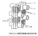
- a general cross fin type (also known as fin and tube type) heat exchanger inserts a heat transfer tube into an insertion hole opened in an aluminum heat radiating fin and then has a larger inside diameter than the inside of the heat transfer tube.
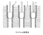
- a mandrel for tube expansion having an outer diameter is pushed in to expand the diameter of the heat transfer tube, and the outer peripheral surface of the heat transfer tube and the insertion hole of the aluminum radiation fin are brought into close contact (tube expansion processing: FIG. 2). Thereafter, the heat transfer tube integrated with the aluminum radiation fin is bent into a hairpin shape, and a heat transfer tube (U-shaped tube) bent in a separate U shape is joined by torch brazing to complete (Non-patent Document 1).
- the heat transfer tube used in the cross fin type heat exchanger is one that causes HFC or the like to flow through the tube as a refrigerant to exchange heat, and a copper heat transfer tube having a trapezoidal or triangular protrusion fin on the inner surface of the tube (Hereinafter referred to as an internally grooved tube) is used to improve the efficiency and energy saving of the heat exchanger.
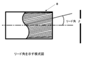
- the depth and bottom thickness of the groove between the projecting fins shown in FIG. Thiickness of the base of the projecting fin), the shape of the fin (vertical angle, etc.), or various transmissions that define the lead angle of the projecting fin shown in FIG.
- a heat pipe has been proposed (for example, Patent Document 1). It is said that the heat transfer performance of the internally grooved tube is superior because the surface area inside the tube is increased compared to the smooth tube, and a uniform refrigerant liquid film is formed in the tube by this groove (non- Patent Document 2).
- the projecting fins arranged in a spiral manner are generally formed on the inner surface of the inner grooved tube by rolling a raw tube (smooth tube).
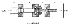
- a rolling method a roll rolling method (see Fig. 3) in which a grooved plug that freely rotates into the pipe is inserted, a roll that freely rotates from the outside of the pipe is pressed, and the pipe is pulled out while rotating planetary (see Fig. 3), or instead of a roll
- a ball rolling method using a ball pressing mechanism is known (Non-patent Document 1, Patent Document 2).
- copper-based materials such as copper and copper alloys have been mainly used for internally grooved pipes, but aluminum-based materials such as aluminum and aluminum alloys (hereinafter referred to as “reducing costs”) , And aluminum alloys) are being studied.
- the heat transfer tube has a two-layer structure, the inner layer of the tube is made of an Al—Mn alloy, and the outer surface layer is coated with an Al—Zn alloy as a sacrificial anticorrosion layer. Grooved tubes have been proposed.
- Patent Document 4 an Al—Mn alloy such as A3003 is used for an inner layer of a heat transfer tube, and an outer surface layer is a sacrificial anticorrosive layer clad with an Al—Zn alloy such as A7072 and the inner grooved tube. Heat exchangers using internally grooved tubes have been proposed.
- Patent Document 5 proposes to form an oxide film having a thickness of 5 ⁇ m or more on the inner surface of the aluminum pipe.
- the inner surface of the aluminum in which the inner layer on which the protruding fins are formed is made of an aluminum alloy layer having a high mechanical strength and the outer layer of the aluminum alloy layer is clad with an aluminum layer having a low mechanical strength.
- Grooved tubes have been proposed.
- an inner layer uses an A3003 aluminum alloy and an outer layer uses A1050 (pure aluminum).
- the outer peripheral tube bottom portion made of A1050 is preferentially deformed and the outer diameter is expanded, and the inner peripheral tube bottom portion made of A3003 is on the inner surface even when the tube is expanded because the deformation amount is small. It is described that the collapse amount of the projection fin can be suppressed to an allowable range or less.
- Patent Document 7 uses a high-strength alloy obtained by adding Zn to an Al—Mn alloy (A3000 alloy) as an outer layer material of an aluminum tube as an internally grooved tube excellent in tube expansion workability. Three layers using an Al-Mn alloy (A3000 alloy) on the inside, and an Al-Mg-Si alloy (A6000 alloy) or Al-Mg alloy (A5000 alloy) with high strength on the inner layer A cladding tube has also been proposed.
- Patent Documents 1 and 2 Non-Patent Documents 1 and 2
- the problems of corrosion resistance and fin crushing when an aluminum alloy is used for a heat transfer tube have not been improved.
- Patent Documents 3 and 4 describe methods for improving the corrosion resistance of heat transfer tubes, but the problem of fin crushing has not been improved.
- Patent Documents 5 to 7 describe methods for improving the fin crushing of heat transfer tubes, but there is room for improvement in the following points. That is, in Patent Document 5, an anodizing process or the like is added as a process for forming an oxide film inside, which causes a significant increase in processing costs and is not realistic. In addition, it is very difficult to perform such treatment on the inside of a generally long tube.
- Patent Document 6 it is necessary to make the thickness ratio of pure aluminum of the outer layer thicker than the A3003 alloy of the inner layer.
- the A1050 outer layer is 0.8 mm and the A3003 inner layer is 0.2 mm, or the A1050 outer layer is 0.7 mm and the A3003 inner layer is 0.3 mm.
- since such a structure reduces the strength of the pipe itself, it is necessary to make the pipe itself a thick-walled pipe in order to obtain a pressure resistance that can withstand the internal pressure of the refrigerant, which increases the material cost and is uneconomical. .
- Patent Document 7 since a three-layer clad tube is used, the manufacturing process is complicated, and productivity and yield are low, so that there is a problem that processing costs increase.
- the present invention has been made from such a viewpoint, and an object of the present invention is to provide an aluminum alloy internally grooved heat transfer tube that is less likely to cause fin crushing even when the tube is mechanically expanded by a mandrel. That is. Another object is to provide an aluminum alloy internally grooved heat transfer tube which is a heat transfer tube in which such fin crushing is unlikely to occur, and which has better corrosion resistance and can be thinned.
- a plurality of fin-shaped fins are formed on the inner surface, Mn: 0.8 to 1.8% by mass (hereinafter referred to as “%”), Cu: 0.3 to There is provided an aluminum alloy internally grooved heat transfer tube comprising 0.8%, Si: 0.3 to 1.0%, the balance being made of Al and inevitable impurities.
- a plurality of protrusion-shaped fins are formed on the inner surface, Mn: 0.8 to 1.8%, Cu: 0.3 to 0.8%, Si: 0.3 to 1. Further, Fe: 0.60% or less, Mg: 0.20% or less, Zn: 0.30% or less, Cr: 0.20% or less, Ti: 0.20% or less, Zr: 0 There is provided an aluminum alloy internally grooved heat transfer tube comprising one or more of 20% or less, the balance being made of Al and inevitable impurities.
- a heat exchanger including any one of the above heat transfer tubes is provided.
- an air conditioner including any one of the above heat transfer tubes is provided.
- the aluminum alloy inner surface grooved heat transfer tube of the present invention has an effect that fin crushing hardly occurs even when the tube is mechanically expanded by a mandrel. Or it has the effect that it is hard to generate
- Heat transfer tube> (1-1) Component
- the heat transfer tube assumed in the present embodiment is used for a heat exchanger for an air conditioner for general households, and the dimensions thereof are, for example, outer diameters ⁇ 4.0 to ⁇ 9. It is a small-diameter thin tube with a thickness of 54 mm and a bottom wall thickness of about 0.3 to 0.6 mm.
- an Al—Mn-based A3003 having an appropriate strength and relatively excellent workability (extrudability, drawability, rollability) for obtaining a small-diameter thin-walled tube.
- the heat transfer tube of the present embodiment has a plurality of ridge-shaped fins formed on the inner surface, Mn: 0.8 to 1.8% by mass (hereinafter referred to as “%”), Cu: 0.3 to An aluminum alloy internally grooved heat transfer tube comprising 0.8%, Si: 0.3 to 1.0%, the balance being made of Al and inevitable impurities.
- This heat transfer tube has an effect that the fin crushing hardly occurs, as demonstrated in the examples described later. Since this heat transfer tube has high pressure resistance, the material cost can be reduced by thinning. Since this heat transfer tube does not necessarily require a complicated production process or a special structure, it is excellent in productivity and quality.
- the heat transfer tube has a plurality of fins on the inner surface, Mn: 0.8 to 1.8%, Cu: 0.3 to 0.8%, Si: 0.3 to 1.0% Fe: 0.60% or less, Mg: 0.20% or less, Zn: 0.30% or less, Cr: 0.20% or less, Ti: 0.20% or less, Zr: 0.20 % Or less, and the balance is made of Al and inevitable impurities, and it is considered that the same effect can be achieved even with an aluminum alloy internally grooved heat transfer tube. .
- the aluminum alloy is an alloy containing Al as a main component.
- the Al content in the aluminum alloy is, for example, 90 to 99.9%.
- the Al content is, for example, 90, 91, 92, 93, 94, 95, 96, 97, 98, 99, 99.5, or 99.9%.
- the Al content may be in any two of the numerical values exemplified here.
- As the alloy system a 3000 series alloy typified by JIS 3003, 3004 or the like and a 6000 series alloy typified by JIS 6061, 6063 or the like are preferably used.
- Mn is a main additive element for improving the strength of 3000 series alloys, and has the effect of giving solid solution, part of which is precipitated and imparting strength, and if the addition amount is less than 0.8%, the heat transfer tube Insufficient strength, and if it exceeds 1.8%, the effect of improving the strength is saturated, and the amount of coarse intermetallic compound increases, so that defects such as cracks are likely to occur in the manufacturing process of the tube. Therefore, the amount of Mn added is in the range of 0.8 to 1.8%. A more preferred range is 1.0 to 1.5%.
- Cu is an element that has the effect of further improving the strength by dissolving in aluminum and does not impair the workability. If the amount added is less than 0.3%, the strength is insufficient and crushing of the groove due to mechanical expansion cannot be prevented, and if it exceeds 0.8%, the extrudability, the drawability and the corrosion resistance deteriorate. Therefore, the Cu addition amount is set in the range of 0.3 to 0.8%. A more preferred range is 0.4 to 0.6%.
- Si When Si is contained in an Al—Mn—Cu alloy, it forms an Al—Mn—Si or Al—Mn—Si—Cu intermetallic compound, which further improves the strength of the Al—Mn—Cu alloy. And an element that does not hinder processability. If the amount added is less than 0.3%, the strength is insufficient and groove crushing due to mechanical expansion cannot be prevented, and if it exceeds 1.0%, extrudability, drawability, rolling workability, and bending workability are obtained. to degrade. Therefore, the Si addition amount is set to a range of 0.3 to 1.0%. A more preferred range is 0.4 to 0.6%.
- Impurities include Fe, Mg, Zn and the like, but these do not impair the effects of the present invention as long as Fe is 0.6% or less, Mg is 0.2% or less, and Zn is 0.3% or less. These content ratios are preferably as small as possible from the viewpoint of not inhibiting the effects of the present invention. Moreover, the lower limit of these content rates is not specifically limited, For example, 0.01, 0.001, 0.0001 or more, or 0% may be sufficient.
- Ti, Cr, Zr may be contained because it has the effect of uniformly refining the ingot structure. However, if it exceeds 0.2%, a giant intermetallic compound is formed or the extrudability is lowered.
- the content is 0.2% or less. Although the lower limit of these content rates is not specifically limited, For example, 0.01, 0.001, 0.0001 or more, or 0% may be sufficient.
- the protrusion fin may have a hardness of HV (Vickers hardness) 35 or more. This is to prevent the occurrence of fin crushing in the pipe expansion process.
- HV Vanders hardness
- the combination of the above Mn, Cu, and Si additions is optimized (basically, a higher combination within the component range), and normal such as annealing and not overheating. The process management may be performed.
- the hardness of the ridge fin is HV35 or more before the pipe expansion process, the ridge fin is not plastically deformed during the pipe expansion process, so the hardness after the pipe expansion process does not change.
- the heat transfer tube of this embodiment is assumed to be used as a heat exchanger for an outdoor unit in a salt damage area along the coast, and pure Al or Al- A Zn-based alloy layer may be provided.
- the heat transfer tube of the present embodiment in which the sacrificial anticorrosion layer is formed is a high-quality heat transfer tube because it is excellent in both corrosion resistance and fin crushing.
- the thickness of these sacrificial anticorrosive layers is preferably 5 to 30% with respect to the total thickness. If the thickness of the sacrificial anticorrosive layer is less than 5% of the total thickness, the effective period of the sacrificial anticorrosive layer in use as a heat exchanger is insufficient, and if it exceeds 30%, the strength of the heat transfer tube is reduced and the thickness is reduced. It becomes difficult.
- This ratio is, for example, 5, 6, 7, 8, 9, 10, 11, 12, 13, 14, 15, 16, 17, 18, 19, 20, 21, 22, 23, 24, 25, 26, 27, 28, 29, or 30%. This ratio may be within the range of any two values exemplified here.
- the sacrificial anticorrosive layer may have a natural potential lower than that of the core Al—Mn—Si—Cu alloy.
- pure aluminum such as A1050 or A7072 (Al-0.8 to 1..
- An Al—Zn alloy such as a 3% Zn alloy may be used as appropriate.
- the combined billet of the Al—Mn—Si—Cu alloy in the heat transfer tube of this embodiment was prepared by bending a sacrificial anticorrosion alloy plate (pure Al or Al—Zn alloy) into a cylindrical shape outside the cylindrical billet. Then, this is heated to 350 to 600 ° C. in a heating furnace and homogenized.
- the combination billet is inserted between the extrusion die and the extrusion ram nose and inserted into the container. With the extrusion die and the extrusion ram nose fixed, a mandrel having an outer diameter larger than the inner diameter of the core material is press-fitted to expand the core material.
- the mandrel is fixed in place, the extrusion hollow stem is advanced, and the combined billet is extruded through a die to obtain a two-layer clad extruded tube.
- the extruded tube is drawn to a predetermined outer diameter and thickness to obtain a two-layer clad elementary tube (smooth tube). For this drawing process, it is desirable to use a draw block type continuous drawing machine with high productivity.
- a cylindrical sacrificial anticorrosive billet is heated to 350 to 600 ° C., and a hollow hollow billet obtained by shrink-fitting a cylindrical core hollow billet inside is extruded, and similarly drawn. It is also possible to obtain a two-layer clad base tube (smooth tube).
- a two-layer clad sheet obtained by clad rolling a sacrificial anti-corrosion material sheet on one side of an aluminum alloy core sheet, and roll-forming the sheet into a tubular shape, and then welding the sheet abutting surface to form a two-layer clad electro-resistance tube It is good.
- the raw pipe (smooth pipe) on which the sacrificial anticorrosive layer is formed in this way be subjected to annealing softening treatment in advance.
- the annealing condition is 300 to 400 ° C. and the time is about 2 to 8 hours.
- these smooth tubes have a slightly reduced outer diameter and wall thickness in the next rolling process. Therefore, the dimensions (outer diameter, wall thickness) of the raw pipe are set larger than the inner grooved pipe as the final product in consideration of the decrease.
- the smooth tube is subjected to rolling by a roll rolling method, a ball rolling method, or the like to produce an internally grooved tube having a ridge-shaped fin.
- the internally grooved tube of the present embodiment can be manufactured in various dimensions according to the use of the heat exchanger, but when used in a domestic air conditioner, production in the manufacture of the tube
- the outer diameter is preferably 4.0 mm or more from the viewpoint of performance, and the outer diameter is preferably 9.95 mm or less from the viewpoint of reducing the size and weight of the heat exchanger.
- This outer diameter is, for example, 4.0, 5.0, 6.0, 6.35, 6.5, 7.0, 7.5, 8.0, 8.5, 9.0, or 9. 54 mm.
- the outer diameter may be within the range of any two values exemplified here.
- the bottom wall thickness is preferably 0.3 or more from the viewpoint of pressure resistance, and 0.6 mm or less from the viewpoint of miniaturization and weight reduction of the heat exchanger.
- the bottom wall thickness is, for example, 0.30, 0.35, 0.40, 0.45, 0.50, 0.55, or 0.60 mm.
- the bottom wall thickness may be within the range of any two values exemplified here.
- the height H of the inner surface ridge fin is 0.1 to 0.4 mm
- the apex angle ⁇ of the inner surface ridge fin is 10 to 40 °
- the number of inner surface ridge fins is 40 or more
- the lead angle ⁇ (inner surface protrusion) is preferably 20 ° or more.
- annealing softening treatment may be performed. This is for removing the processing distortion introduced at the time of rolling and facilitating hairpin bending (meandering bending). Annealing may be performed at 300 to 400 ° C. for about 2 to 8 hours by a conventional method.
- the inner grooved tube of the present embodiment manufactured in this way is brought into close contact with the insertion hole of the aluminum heat radiating fin by pipe expansion processing.
- the pipe expanding process can improve production efficiency by a hydraulic pipe expanding method in which an internal pressure is applied to the pipe by hydraulic pressure or water pressure instead of a mechanical pipe expanding method using a mandrel.
- Heat exchanger> Other embodiment of this invention is a heat exchanger provided with the heat exchanger tube which concerns on said embodiment. Since this heat exchanger includes a heat transfer tube in which fin crushing is difficult to occur, heat transfer performance is good and efficiency is excellent. Or since this heat exchanger is equipped with the heat exchanger tube which is hard to generate
- Air conditioner> Other embodiment of this invention is an air conditioner provided with the heat exchanger tube which concerns on said embodiment. Since this air conditioner includes a heat transfer tube in which fins are not easily crushed, heat transfer performance is good and efficiency is high. Or since this air conditioner is equipped with the heat exchanger tube which is hard to generate
- a cylindrical billet of an aluminum alloy having the composition shown in Table 1 was cast, and an extruded tube having an outer diameter of 47 mm and a wall thickness of 3.5 mm was obtained by an indirect extrusion method.
- the extruded tube was subjected to a drawing process using a draw block type continuous drawing machine to obtain a drawn tube having an outer diameter of 10 mm and a wall thickness of 0.45 mm.
- the drawn tube thus obtained is annealed and softened at 360 ° C. for 2 hours, and then a floating plug, a rod and a plug with a grooved plug are inserted, and a floating die, a machining head, and a molding die are inserted.
- the inner surface is grooved by passing it through, the outer diameter: ⁇ 7 mm, the bottom wall thickness: 0.35 mm, the height H of the ridge fins: 0.22 mm, the number of ridge fins is 50, the apex angle ⁇ :
- An internally grooved tube having a lead angle ⁇ of 35 ° was prepared. For Nos. 8 to 14 and Nos.
- the sacrificial anticorrosive layer was adjusted by the billet thickness of the sacrificial anticorrosive material in the extrusion process so that the sacrificial anticorrosive layer was 0.035 mm (ratio of 10% with respect to the bottom wall thickness). . Furthermore, the annealing softening process was finally performed at 360 degreeC for 2 hours, and the internally grooved pipe was completed.
- the aluminum inner grooved tubes No1 to No14 of the present invention have a reduction amount of the fin height H (fin collapse amount) of 0.01 mm or less.
- the fin crush amounts of No. 3 to No. 7 and No. 10 to No. 14 where the hardness of the fin portion is HV35 or higher are zero and extremely good.
- No. 8 to No. 14 formed with the sacrificial anticorrosive layer no through-holes are observed and the external corrosion resistance is good.
- the tensile strength of the pipe is 118 MPa or more, which is higher than that of, for example, 97 MPa (corresponding to A3003) of Comparative Example No. 16, and therefore the pressure resistance of the pipe is also high, so that the material cost can be reduced by thinning.
- No. 15 to No. 17 and No. 21 to No. 23 with a small amount of Mn, Cu, and Si have a large crushing of the projecting fins at the time of tube expansion, and the strength of the tube itself is also low.
- No18 to No20 and No24 to No26 with large amounts of Mn, Cu, and Si were cracked in the drawing process and the rolling process, and the inner grooved tube itself could not be manufactured.
Landscapes
- Engineering & Computer Science (AREA)
- Mechanical Engineering (AREA)
- Chemical & Material Sciences (AREA)
- Physics & Mathematics (AREA)
- Thermal Sciences (AREA)
- General Engineering & Computer Science (AREA)
- Materials Engineering (AREA)
- Metallurgy (AREA)
- Organic Chemistry (AREA)
- Geometry (AREA)
- Crystallography & Structural Chemistry (AREA)
- Heat-Exchange Devices With Radiators And Conduit Assemblies (AREA)
- Extrusion Of Metal (AREA)
- Rigid Pipes And Flexible Pipes (AREA)
Abstract
Description
第一に、特許文献1、2、非特許文献1,および2においては、アルミニウム合金を伝熱管に使用した際の耐食やフィン潰れの問題が改善されていなかった。
すなわち、本発明によれば、内面に複数の突条型のフィンが形成され、Mn:0.8~1.8質量%(以下、質量%を、%と記載)、Cu:0.3~0.8%、Si:0.3~1.0%を含有し、残部がAlと不可避的不純物からなることを特徴とするアルミニウム合金製内面溝付き伝熱管が提供される。
(1-1)成分
本実施形態において想定している伝熱管は、一般家庭向け空気調和機用の熱交換器に使用するものであり、その寸法は、例えば、外径φ4.0~φ9.54mm、底肉厚0.3~0.6mm程度の小径薄肉管である。このため、各種のアルミニウム合金のうち、適度な強度を有し、かつ小径薄肉管を得るための加工性(押出性、抽伸性、転造性)に比較的優れているAl-Mn系のA3003合金(Al-1.0~1.5%Mn-0.05~0.20%Cu合金)をベースとして、添加元素調整により加工性を損なわずに強度を向上させることで拡管加工によるフィン潰れを防止するアルミニウム合金を得るものである。
Mnは3000系合金において強度を向上させる主要な添加元素であり、アルミニウム中に固溶、一部は析出して強度を付与する効果をもち、その添加量が0.8%より少ないと伝熱管としての強度が不十分であり、1.8%より多いと強度向上効果が飽和するうえ、粗大な金属間化合物の量が多くなり管の製造工程において割れなどの不具合が発生しやすくなる。したがって、Mn添加量は0.8~1.8%の範囲とする。更に好ましい範囲は1.0~1.5%である。
本実施形態においてはさらに突条フィンの硬さをHV(ヴィッカース硬さ)35以上であっても良い。これは拡管加工においてフィン潰れが発生しないようにするためである。この硬さを制御するために、具体的には上記Mn、Cu、Si添加量の組合せを適正化(基本的には成分範囲内で高めの組合せ)するとともに、焼鈍で過加熱しない等の通常の工程管理をおこなえばよい。なお、突条フィンの硬さは拡管加工前にHV35以上であれば、拡管加工時に突条フィンが塑性変形することは無いので、拡管加工後の硬さも変わることはない。
本実施形態の伝熱管は、海岸沿いの塩害地等において室外機の熱交換器として使用する場合を想定し、伝熱管外面に犠牲防食層として純AlまたはAl-Zn系合金層を設けても良い。犠牲防食層を形成した本実施例の伝熱管は、耐食性とフィン潰れの両面から優れているため、高品質の伝熱管である。
本実施形態の伝熱管におけるAl-Mn-Si-Cu系合金の、円筒状ビレットの外側に犠牲防食合金板材(純AlまたはAl-Zn系合金)を円筒状に曲げ被せた組み合わせビレットを作製し、これを加熱炉により350~600℃に加熱し均質化処理をおこなう。この組み合わせビレットを押出ダイスと押出ラムノーズ間に挟持してコンテナ内に挿入し、押出ダイスと押出ラムノーズを固定した状態で、芯材内径より大きな外径を持つマンドレルを圧入し、芯材を拡管して芯材と外皮材間の空気を追い出す。次にマンドレルを所定にの位置に固定して、押出ホローステムを前進させダイスを通して組み合わせビレットを押出し、2層クラッド押出管を得る。次いで該押出管を所定の外径、肉厚に抽伸加工し、2層クラッドの素管(平滑管)を得る。この抽伸加工は生産性の高いドローブロック式連続抽伸機を使用することが望ましい。
本実施形態の内面溝付き管は、熱交換器の用途に応じて種々の寸法で製造できるが、家庭用空気調和機に使用する場合、管の製造における生産性の面からは外径φ4.0以上が好ましく、熱交換器の小型化・軽量化の面からは外径φ9.54mm以下が好ましい。この外径は、例えば、4.0、5.0、6.0、6.35、6.5、7.0、7.5、8.0、8.5、9.0、または9.54mmである。またこの外径は、ここで例示した何れか2つの値の範囲内であってもよい。
本発明の他の実施形態は、上記の実施形態に係る伝熱管を備える熱交換器である。この熱交換器は、フィン潰れが発生し難い伝熱管を備えているため、伝熱性能が良く、効率性に優れている。または、この熱交換器はフィン潰れが発生し難く、且つ耐食性に優れた伝熱管を備えているため、伝熱性能および耐久性に優れている。
本発明の他の実施形態は、上記の実施形態に係る伝熱管を備える空気調和機である。この空気調和機は、フィン潰れが発生し難い伝熱管を備えているため、伝熱性能が良く、効率性に優れている。または、この空気調和機はフィン潰れが発生し難く、且つ耐食性に優れた伝熱管を備えているため、伝熱性能および耐久性に優れている。
表1に示す成分組成のアルミニウム合金の円筒状ビレットを鋳造し、間接押出法により外径φ47mm、肉厚3.5mmの押出管を得た。この押出管にドローブロック式連続抽伸機により抽伸加工を施し、外径φ10mm、肉厚0.45mmの抽伸管を得た。

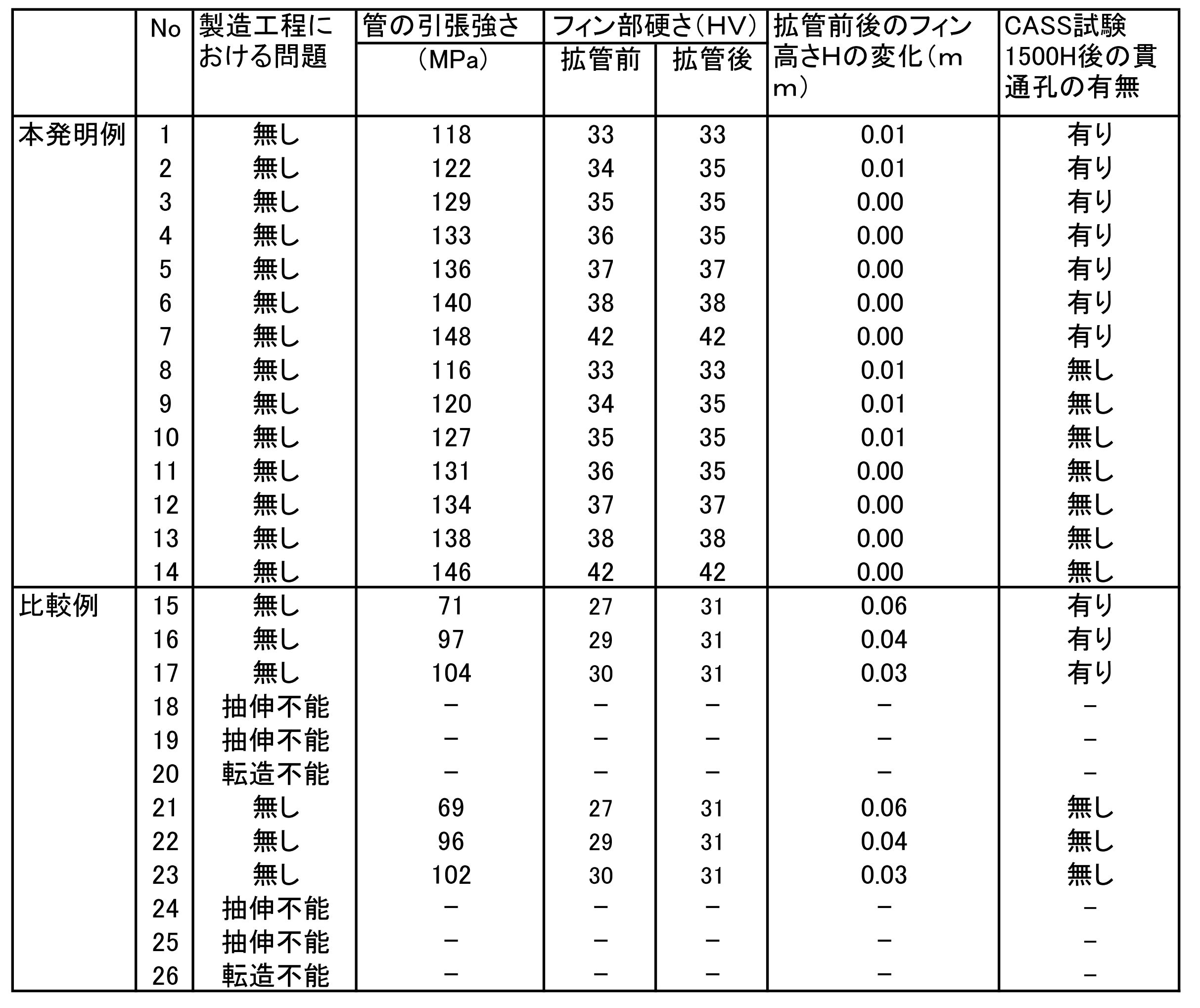
内面溝付き管の強度を測定するため、JIS Z2241に準じ引張試験を実施した。
上記外径φ7mmの内面溝付き管を、鋼製マンドレルを使用し外径が5%増加するように拡管加工を行った。その後、管断面を観察し、突条フィン高さHの減少量を測定してフィン潰れ量を評価した。熱交換器としての伝熱特性を得るためには、このフィン潰れ量は0.01mm以下であることが望ましい。また拡管加工前後の突条フィン断面の中央部の硬さをマイクロヴィッカース硬度計で測定した。
外部耐食性を評価するために、各内面溝付き管についてJIS Z8681に準じCASS試験を1500時間行った。試験後、供試管の表面腐食生成物を除去して、管の腐食状況を観察し、貫通孔の有無により外部耐食性を評価した。
2 伝熱管(内面溝付管)
3 ルーバー
4 拡管プラグ(マンドレル)
5 素管(平滑管)
6 転造プラグ
7 回転ロール
8 内面螺旋溝付管
9 突条フィン
10 犠牲防食層
Claims (8)
- 内面に複数の突条型のフィンが形成され、Mn:0.8~1.8質量%(以下、質量%を、%と記載)、Cu:0.3~0.8%、Si:0.3~1.0%を含有し、残部がAlと不可避的不純物からなることを特徴とするアルミニウム合金製内面溝付き伝熱管。
- 内面に複数の突条型のフィンが形成され、Mn:0.8~1.8%、Cu:0.3~0.8%、Si:0.3~1.0%を含有し、更にFe:0.60%以下、Mg:0.20%以下、Zn:0.30%以下、Cr:0.20%以下、Ti:0.20%以下、Zr:0.20%以下の中から1種又は2種以上を含有し、残部がAlと不可避的不純物からなることを特徴とするアルミニウム合金製内面溝付き伝熱管。
- 請求項1または2に記載の伝熱管であって、
前記突条型のフィンの硬さがHV35以上であることを特徴とする、伝熱管。 - 請求項1または2に記載の伝熱管であって、
外面に犠牲防食材として純AlまたはAl-Zn系合金層を形成したことを特徴とする、伝熱管。 - 請求項1または2に記載の伝熱管であって、
前記伝熱管の外径が、4.0~9.54mmである、伝熱管。 - 請求項1または2に記載の伝熱管であって、
前記伝熱管の底肉厚が、0.3~0.6mmである、伝熱管。 - 請求項1または2に記載の伝熱管を備える、熱交換器。
- 請求項1または2に記載の伝熱管を備える、空気調和機。
Priority Applications (3)
| Application Number | Priority Date | Filing Date | Title |
|---|---|---|---|
| KR1020137001783A KR20130043659A (ko) | 2010-07-13 | 2011-07-12 | 알루미늄 합금으로 제조된 내면홈을 가지는 전열관 |
| CN2011800342643A CN103003655A (zh) | 2010-07-13 | 2011-07-12 | 铝合金制内面带槽传热管 |
| JP2012524562A JP6154610B2 (ja) | 2010-07-13 | 2011-07-12 | アルミニウム合金製内面溝付き伝熱管 |
Applications Claiming Priority (2)
| Application Number | Priority Date | Filing Date | Title |
|---|---|---|---|
| JP2010158849 | 2010-07-13 | ||
| JP2010-158849 | 2010-07-13 |
Publications (1)
| Publication Number | Publication Date |
|---|---|
| WO2012008463A1 true WO2012008463A1 (ja) | 2012-01-19 |
Family
ID=45469460
Family Applications (1)
| Application Number | Title | Priority Date | Filing Date |
|---|---|---|---|
| PCT/JP2011/065906 Ceased WO2012008463A1 (ja) | 2010-07-13 | 2011-07-12 | アルミニウム合金製内面溝付き伝熱管 |
Country Status (5)
| Country | Link |
|---|---|
| JP (1) | JP6154610B2 (ja) |
| KR (1) | KR20130043659A (ja) |
| CN (1) | CN103003655A (ja) |
| MY (1) | MY173745A (ja) |
| WO (1) | WO2012008463A1 (ja) |
Cited By (6)
| Publication number | Priority date | Publication date | Assignee | Title |
|---|---|---|---|---|
| JP2013190191A (ja) * | 2012-03-15 | 2013-09-26 | Sumitomo Light Metal Ind Ltd | 熱交換器用アルミニウム合金扁平管及びその製造方法並びに熱交換器コア及びその製造方法 |
| JPWO2013153972A1 (ja) * | 2012-04-13 | 2015-12-17 | 株式会社Uacj | アルミニウム合金製内面溝付き伝熱管 |
| CN105890433A (zh) * | 2016-04-25 | 2016-08-24 | 江苏金源腾峰换热设备有限公司 | 一种双金属空气冷却器用钛合金翅片及其处理工艺 |
| JP2016223768A (ja) * | 2016-07-05 | 2016-12-28 | 三菱アルミニウム株式会社 | 熱交換器 |
| WO2021014203A1 (en) * | 2019-07-22 | 2021-01-28 | Hydro Precision Tubing (Suzhou) Co., Ltd. | Long-life aluminum alloy with a high corrosion resistance and helically grooved tube produced from the alloy |
| NO349576B1 (en) * | 2025-01-09 | 2026-03-02 | Hydro Extruded Solutions As | System and method for manufacturing of helical inner grooved tubes |
Families Citing this family (6)
| Publication number | Priority date | Publication date | Assignee | Title |
|---|---|---|---|---|
| CN105112738B (zh) * | 2015-09-28 | 2017-08-11 | 亚太轻合金(南通)科技有限公司 | 高强度耐腐蚀铝合金的制备工艺及高强度耐腐蚀铝合金 |
| CN105499430A (zh) * | 2015-12-08 | 2016-04-20 | 安阳方快锅炉有限公司 | 一种锅炉用内翅片管的加工方法 |
| CN105543575B (zh) * | 2015-12-21 | 2017-11-28 | 无锡市世达精密焊管制造有限公司 | 一种富含硅、铜和钛元素的铝合金板锭及其制备方法 |
| CN107575657A (zh) * | 2017-10-24 | 2018-01-12 | 陕西海恩得工贸有限公司 | 一种耐腐蚀换热器用钛管 |
| CN107619970A (zh) * | 2017-10-26 | 2018-01-23 | 江苏亚太安信达铝业有限公司 | 用于家用空调复合管材的铝合金及其制备方法 |
| CN108344322B (zh) * | 2018-03-28 | 2023-12-15 | 长沙格力暖通制冷设备有限公司 | 翅片换热器及空调器 |
Citations (3)
| Publication number | Priority date | Publication date | Assignee | Title |
|---|---|---|---|---|
| JPH09155443A (ja) * | 1995-12-04 | 1997-06-17 | Mitsubishi Shindoh Co Ltd | 内面溝付伝熱管の製造方法および製造装置 |
| JP2008267714A (ja) * | 2007-04-20 | 2008-11-06 | Furukawa Sky Kk | 成形性に優れたアルミニウム製内面溝付き管およびその製造方法 |
| JP2010085065A (ja) * | 2008-10-02 | 2010-04-15 | Mitsubishi Alum Co Ltd | フィンチューブ型エアコン熱交換器用アルミニウム合金押出チューブ |
Family Cites Families (8)
| Publication number | Priority date | Publication date | Assignee | Title |
|---|---|---|---|---|
| JPH07164181A (ja) * | 1993-12-13 | 1995-06-27 | Daiichi Meteko Kk | アルミニウム合金製熱交換器およびその製造方法 |
| JP3217607B2 (ja) * | 1994-08-24 | 2001-10-09 | 古河電気工業株式会社 | 疲労強度と耐食性に優れる熱交換器用アルミ合金複合材 |
| JPH11351791A (ja) * | 1998-06-09 | 1999-12-24 | Hitachi Cable Ltd | アルミニウム製内面溝付管 |
| JP3402234B2 (ja) * | 1999-01-11 | 2003-05-06 | 日立電線株式会社 | 内面溝付アルミニウム管及びその製造方法 |
| US6908520B2 (en) * | 1999-05-28 | 2005-06-21 | The Furukawa Electric Co., Ltd. | Aluminum alloy hollow material, aluminum alloy extruded pipe material for air conditioner piping and process for producing the same |
| CN1726114A (zh) * | 2002-12-12 | 2006-01-25 | 昭和电工株式会社 | 铝合金钎焊材料、钎焊件、使用所述材料的钎焊制品及其钎焊方法,钎焊热交换管、使用所述钎焊热交换管的热交换器及其制造方法 |
| JP2006145060A (ja) * | 2004-11-16 | 2006-06-08 | Denso Corp | アルミニウム熱交換器 |
| JP4777119B2 (ja) * | 2006-04-07 | 2011-09-21 | 株式会社デンソー | アルミニウム製熱交換器の製造方法 |
-
2011
- 2011-07-12 MY MYPI2013000104A patent/MY173745A/en unknown
- 2011-07-12 KR KR1020137001783A patent/KR20130043659A/ko not_active Withdrawn
- 2011-07-12 CN CN2011800342643A patent/CN103003655A/zh active Pending
- 2011-07-12 JP JP2012524562A patent/JP6154610B2/ja active Active
- 2011-07-12 WO PCT/JP2011/065906 patent/WO2012008463A1/ja not_active Ceased
Patent Citations (3)
| Publication number | Priority date | Publication date | Assignee | Title |
|---|---|---|---|---|
| JPH09155443A (ja) * | 1995-12-04 | 1997-06-17 | Mitsubishi Shindoh Co Ltd | 内面溝付伝熱管の製造方法および製造装置 |
| JP2008267714A (ja) * | 2007-04-20 | 2008-11-06 | Furukawa Sky Kk | 成形性に優れたアルミニウム製内面溝付き管およびその製造方法 |
| JP2010085065A (ja) * | 2008-10-02 | 2010-04-15 | Mitsubishi Alum Co Ltd | フィンチューブ型エアコン熱交換器用アルミニウム合金押出チューブ |
Cited By (11)
| Publication number | Priority date | Publication date | Assignee | Title |
|---|---|---|---|---|
| JP2013190191A (ja) * | 2012-03-15 | 2013-09-26 | Sumitomo Light Metal Ind Ltd | 熱交換器用アルミニウム合金扁平管及びその製造方法並びに熱交換器コア及びその製造方法 |
| JPWO2013153972A1 (ja) * | 2012-04-13 | 2015-12-17 | 株式会社Uacj | アルミニウム合金製内面溝付き伝熱管 |
| CN105890433A (zh) * | 2016-04-25 | 2016-08-24 | 江苏金源腾峰换热设备有限公司 | 一种双金属空气冷却器用钛合金翅片及其处理工艺 |
| JP2016223768A (ja) * | 2016-07-05 | 2016-12-28 | 三菱アルミニウム株式会社 | 熱交換器 |
| WO2021014203A1 (en) * | 2019-07-22 | 2021-01-28 | Hydro Precision Tubing (Suzhou) Co., Ltd. | Long-life aluminum alloy with a high corrosion resistance and helically grooved tube produced from the alloy |
| US20220259704A1 (en) * | 2019-07-22 | 2022-08-18 | HYDRO PRECISION TUBING (SUZHOU) CO., Ltd | Long-life aluminum alloy with a high corrosion resistance and helically grooved tube produced from the alloy |
| JP2022541891A (ja) * | 2019-07-22 | 2022-09-28 | ヒドロ・プレシジョン・チュービング(スーチョウ)カンパニー・リミテッド | 耐食性に優れる長寿命アルミニウム合金及びその合金から製造された螺旋溝付管 |
| JP7524299B2 (ja) | 2019-07-22 | 2024-07-29 | ヒドロ・プレシジョン・チュービング(スーチョウ)カンパニー・リミテッド | 耐食性に優れる長寿命アルミニウム合金及びその合金から製造された螺旋溝付管 |
| US12584197B2 (en) * | 2019-07-22 | 2026-03-24 | HYDRO PRECISION TUBING (SUZHOU) CO., Ltd | Long-life aluminum alloy with a high corrosion resistance and helically grooved tube produced from the alloy |
| NO349576B1 (en) * | 2025-01-09 | 2026-03-02 | Hydro Extruded Solutions As | System and method for manufacturing of helical inner grooved tubes |
| WO2026149963A1 (en) * | 2025-01-09 | 2026-07-16 | Hydro Extruded Solutions As | System and method for manufacturing of helical inner grooved tubes |
Also Published As
| Publication number | Publication date |
|---|---|
| KR20130043659A (ko) | 2013-04-30 |
| JPWO2012008463A1 (ja) | 2013-09-09 |
| MY173745A (en) | 2020-02-18 |
| JP6154610B2 (ja) | 2017-06-28 |
| CN103003655A (zh) | 2013-03-27 |
Similar Documents
| Publication | Publication Date | Title |
|---|---|---|
| JP6154610B2 (ja) | アルミニウム合金製内面溝付き伝熱管 | |
| JP6154611B2 (ja) | アルミニウム合金製内面溝付き伝熱管 | |
| JP6105561B2 (ja) | アルミニウム合金製内面溝付き伝熱管 | |
| JP5089232B2 (ja) | 3層クラッドアルミニウム管およびアルミニウム製内面溝付き管の製造方法 | |
| US20090308481A1 (en) | Cu/Al COMPOSITE PIPE AND A MANUFACTURING METHOD THEREOF | |
| JP2002161323A (ja) | 成形性及びろう付け性に優れた熱交換器用アルミニウム合金フィン材 | |
| JPH10265881A (ja) | オイルクーラーの内管用複合パイプとその製造方法及びこのパイプを用いた二重管式オイルクーラーと一体型熱交換器 | |
| JP2010085065A (ja) | フィンチューブ型エアコン熱交換器用アルミニウム合金押出チューブ | |
| CN107109531A (zh) | 换热器用内面带槽管及其制造方法 | |
| JP2010185646A (ja) | フィンチューブ型エアコン熱交換器用アルミニウム合金押出チューブ | |
| JP2006213934A (ja) | 熱交換器用チューブおよびその製造方法 | |
| JP5357403B2 (ja) | 成形性に優れたアルミニウム製内面溝付き管およびその製造方法 | |
| US20220259704A1 (en) | Long-life aluminum alloy with a high corrosion resistance and helically grooved tube produced from the alloy | |
| JP5006155B2 (ja) | 伝熱管 | |
| JP2016028219A (ja) | 押出性に優れた内面溝付管 | |
| JP5607294B2 (ja) | 伝熱管 | |
| JP6244213B2 (ja) | 熱交換器用銅管 | |
| JP5208562B2 (ja) | 継目無管 | |
| JP5882615B2 (ja) | エアコン用アルミニウム合金製内面溝付き管及びその溝付き管を備えるエアコン並びにアルミニウム合金内面溝付き管の製造方法及びエアコン用アルミニウム内面溝付き管の製造方法 | |
| JP2013224768A (ja) | 内面溝付き2層クラッドアルミニウム合金管、及び、熱交換器、並びに、内面溝付き2層クラッドアルミニウム合金管の製造方法 | |
| CN103765152A (zh) | 无缝管、平绕盘管和交叉翅片管型热交换器及其制造方法 | |
| JP7627936B2 (ja) | Al系内面溝付伝熱管及びその製造方法 | |
| CN114888117A (zh) | 一种铝基复合管及其制造方法 | |
| JP2010185647A (ja) | フィンチューブ型エアコン熱交換器用アルミニウム合金押出チューブ | |
| JP6101969B2 (ja) | レベルワウンドコイル、レベルワウンドコイルの製造方法、クロスフィンチューブ型熱交換器及びクロスフィンチューブ型熱交換器の製造方法 |
Legal Events
| Date | Code | Title | Description |
|---|---|---|---|
| 121 | Ep: the epo has been informed by wipo that ep was designated in this application |
Ref document number: 11806793 Country of ref document: EP Kind code of ref document: A1 |
|
| WWE | Wipo information: entry into national phase |
Ref document number: 2012524562 Country of ref document: JP |
|
| NENP | Non-entry into the national phase |
Ref country code: DE |
|
| ENP | Entry into the national phase |
Ref document number: 20137001783 Country of ref document: KR Kind code of ref document: A |
|
| 122 | Ep: pct application non-entry in european phase |
Ref document number: 11806793 Country of ref document: EP Kind code of ref document: A1 |