WO2012008241A1 - 車両用カーテンエアバッグ装置 - Google Patents
車両用カーテンエアバッグ装置 Download PDFInfo
- Publication number
- WO2012008241A1 WO2012008241A1 PCT/JP2011/063021 JP2011063021W WO2012008241A1 WO 2012008241 A1 WO2012008241 A1 WO 2012008241A1 JP 2011063021 W JP2011063021 W JP 2011063021W WO 2012008241 A1 WO2012008241 A1 WO 2012008241A1
- Authority
- WO
- WIPO (PCT)
- Prior art keywords
- vehicle
- chamber
- guide seam
- gas
- airbag
- Prior art date
- Legal status (The legal status is an assumption and is not a legal conclusion. Google has not performed a legal analysis and makes no representation as to the accuracy of the status listed.)
- Ceased
Links
Images



Classifications
-
- B—PERFORMING OPERATIONS; TRANSPORTING
- B60—VEHICLES IN GENERAL
- B60R—VEHICLES, VEHICLE FITTINGS, OR VEHICLE PARTS, NOT OTHERWISE PROVIDED FOR
- B60R21/00—Arrangements or fittings on vehicles for protecting or preventing injuries to occupants or pedestrians in case of accidents or other traffic risks
- B60R21/02—Occupant safety arrangements or fittings, e.g. crash pads
- B60R21/16—Inflatable occupant restraints or confinements designed to inflate upon impact or impending impact, e.g. air bags
- B60R21/23—Inflatable members
- B60R21/231—Inflatable members characterised by their shape, construction or spatial configuration
- B60R21/232—Curtain-type airbags deploying mainly in a vertical direction from their top edge
Definitions
- the present invention is capable of accurately ensuring the occupant protection performance even when the occupant is in the non-regular position, and appropriately incorporating the occupant protection function against the occupant's release from the vehicle and the side collision,
- the present invention relates to a curtain air bag device for a vehicle that can satisfy all three occupant protection performances.
- Patent Document 1 is known as a curtain airbag device for a vehicle in which an airbag body is deployed and inflated downward along a side window from a roof.
- the “head protection airbag device” of Patent Document 1 has an object to provide a head protection airbag device capable of generating a high tension along the vehicle longitudinal direction on the lower edge side of the airbag when deployment and inflation are completed.
- a tension in the front-rear direction is generated in each of the inflating shielding portions by the inflating portions partitioned by the partitioning portions in each of the inflating shielding portions.
- the respective expansion shielding portions are connected to each other on the lower edge side of the airbag by an expansion communication portion at a position below the plate-like portion that does not allow the inflation gas to flow.
- the expansion communication portion is disposed in the front-rear direction along the lower edge of the airbag, and the expansion shield portions can be connected to each other without lowering the tension generated in the expansion shield portions. Overall, a high tension along the front-rear direction can be generated.
- Patent Document 1 discloses that a high tension along the front-rear direction is generated on the entire lower edge of the airbag by an inflating communication portion that is a plate-like portion that does not allow the inflating gas to flow, so that an occupant particularly at the time of rollover of a vehicle. It is designed to prevent the vehicle from being released.
- the overall performance of the airbag is not limited to the occupant protection performance by preventing the occupant from being released, but not only when the occupant is seated in a normal posture, but also when the occupant's head is close to the side window, It is necessary to secure occupant protection performance in the case of out-of-position) and occupant protection performance against side collisions, and it is desired to devise a curtain airbag device for a vehicle that can satisfy all three protection performances. .
- the present invention was devised in view of the above-described conventional problems, and even when the occupant is in a non-regular position, the occupant protection performance can be ensured accurately, and the occupant's release prevention function and side surface It is an object of the present invention to provide a curtain airbag device for a vehicle that can appropriately incorporate an occupant protection function against a collision and can satisfy all three occupant protection performances.
- a curtain airbag device for a vehicle is a curtain airbag device for a vehicle having an airbag body that is deployed and inflated downward along a side window from a roof, and the airbag body uses an inflator gas.
- a gas introduction port to be introduced and a main chamber formed in an airbag space surrounded by the seam, wherein the main chamber is formed by connecting and bending at least the upper lateral guide seam portion and the vertical guide seam portion.
- the inflator gas flows along the vehicle longitudinal direction in communication with the gas introduction port.
- a gas duct is formed, communicated with the gas introduction port on the side of the vertical guide seam part, and a gas flow in which inflator gas flows downward in the vehicle and flows under the upper horizontal guide seam part through the vertical guide seam part.
- a vertical gas duct is formed, and the main chamber is expanded and expanded obliquely downward in the longitudinal direction of the vehicle with a gas flow that flows into and fills the inside of the guide seam from both the horizontal gas duct and the vertical gas duct.
- a curtain airbag device for a vehicle is a curtain airbag device for a vehicle including an airbag main body that is deployed and inflated downward along a side window from a roof, and the airbag main body includes an inflator.
- a gas introduction port for introducing gas and a pair of front and rear front main chambers and rear main chambers arranged in parallel in the vehicle front-rear direction in an airbag space surrounded by a seam, wherein the front main chamber includes at least an upper lateral guide
- a vertical guide seam portion is connected to the rear end of the seam portion, and is bent and surrounded by a front guide seam formed in the airbag space, and the rear main chamber includes at least an upper lateral guide seam.
- the vertical guide seam is connected to the front end of the part and bent.
- the inflator gas flows to the front and rear of the vehicle in communication with the gas introduction port.
- a lateral gas duct is formed as a gas flow that circulates toward the vertical guide seam portion through the guide seam portion, and the vertical guide seam portions of the front guide seam and the rear guide seam are disposed to face each other.
- the inflator gas communicates with the gas introduction port, and the inflator gas flows downward to the vehicle and generates a gas flow that wraps around the upper horizontal guide seam portion via the vertical guide seam portion.
- a vertical chamber is formed that expands and expands downward, and the front main chamber and the upper chamber are formed.
- Each of the rear main chambers is expanded and expanded toward the vehicle front diagonally downward and the vehicle rear diagonally downward with a gas flow that flows into and fills the inside of the front guide seam and the inside of the rear guide seam from both the lateral gas duct and the vertical chamber. It is characterized by that.
- the vertical chamber is positioned at the B-pillar position of the vehicle and is deployed and inflated so as to overlap along the B-pillar so that the airbag main body is pulled inward of the vehicle.
- the airbag main body is formed with a front chamber that is in communication with the front main chamber and into which inflator gas flows in, in front of the front main chamber. It is desirable to be positioned at the pillar position and to be deployed and inflated so as to overlap the A pillar.
- At least the front chamber is formed with an outer contour that lowers below the belt line so that the front chamber overlaps with the belt line of the vehicle door when expanded.
- a rear chamber is formed in the airbag main body at a rear side of the rear main chamber and communicated with the rear main chamber and into which inflator gas flows.
- the rear chamber is positioned at a C pillar position of the vehicle. It is preferable that the C pillar is expanded and inflated.
- an additional seam portion is formed in parallel with the vertical guide seam portion from the upper lateral guide seam portion in order to partition the rear main chamber forward and backward.
- An additional chamber that is in communication with the rear chamber and into which inflator gas flows is formed in the airbag main body behind the rear chamber, and the additional chamber is deployed and inflated behind the C pillar. preferable.
- the occupant protection performance can be accurately ensured even when the occupant is in the non-regular position, and the occupant protection function against the occupant's outside release and the side collision Can be appropriately incorporated, and all three passenger protection performances can be satisfied.
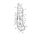
- FIG. 1 is a front view showing a preferred embodiment of a curtain airbag device for a vehicle according to the present invention in a state where an airbag main body is deployed and inflated inside a vehicle. It is front sectional drawing of the airbag main body of the curtain airbag apparatus for vehicles shown in FIG.
- FIG. 2 is a cross-sectional view taken along line AA in FIG. It is a principal part enlarged view which shows the modification of the curtain airbag apparatus for vehicles concerning this invention. It is a principal part enlarged view which shows the other modification of the curtain airbag apparatus for vehicles concerning this invention.
- FIG. 1 is a front view showing a state in which an airbag body of a curtain airbag device for a vehicle according to the present embodiment is deployed and inflated inside the vehicle
- FIG. 2 is an airbag of the curtain airbag device for a vehicle shown in FIG.
- FIG. 3 is a front sectional view of the main body
- FIG. 3 is a sectional view taken along line AA in FIG.
- the vehicle curtain airbag device 1 mainly includes an airbag body 2 that is deployed and inflated, and an inflator 3 that introduces an inflator gas G into the airbag body 2.
- the airbag main body 2 of the curtain airbag device 1 for a vehicle has a length dimension that covers from the position of the A pillar 4 to the rear side window 9 behind the C pillar 6 along the longitudinal direction of the vehicle. It is formed.
- the airbag main body 2 has a front side window 7 between the A pillar 4 and the B pillar 5 and a central side window 8 between the B pillar 5 and the C pillar 6 in the vertical direction of the vehicle. , As well as the height dimension covering all of the rear side window 9.
- the airbag main body 2 is attached to the roof of the vehicle, specifically, the periphery of the roof side rail 10 and fixed to the periphery of the roof side rail 10 while being wound or folded. Stored and installed.
- the rear end portion of the airbag main body 2 is connected to the roof and its peripheral portion at the rear position of the rear side window 9.
- a strap 11 that connects the front edge of the airbag body 2 and the A pillar 4 is housed and provided inside the A pillar 4.
- the inflator 3 is in the form of a cylinder and is attached and fixed to the periphery of the roof side rail 10 behind the B pillar 5.
- the airbag body 2 is directed downward along the side windows 7 to 9 from the roof side rail 10. It is designed to expand and expand.
- the airbag body 2 is formed by joining one cloth material folded or overlapped or two cloth materials overlapped with an annular seam S by stitching or joining. You may form by the bag weave in which an edge part forms a seam.
- an airbag space is formed inside the annular seam S. Even if the seam S is not ring-shaped, it is only necessary that the airbag space can be formed inside the seam S by connection with other seams.
- a gas introduction port 12 into which the inflator 3 is inserted and the inflator gas G is introduced is formed in a form in which this is partially cut away.
- the gas introduction port 12 is formed at the center of the upper end of the airbag body 2, and in the illustrated example, at the rear position of the B pillar 5.
- Inflator gas G is introduced from the gas introduction port 12 into the airbag space surrounded by the annular seam S.
- a pair of front and rear front main chambers 14 and 15 are formed in parallel in the vehicle front-rear direction by a combination of the annular seam S and the guide seam 13.
- a front guide seam 13 is formed in the airbag space.
- the front guide seam 13 may be formed by continuous bonding or intermittent bonding.
- the front guide seam 13 includes, in parallel with the upper edge Su of the annular seam S, an upper lateral guide seam portion 13a extending from the front of the B pillar 5 toward the A pillar 4 in the longitudinal direction of the vehicle, It is formed from a vertical guide seam portion 13b extending along the pillar 5 downward in the height direction of the vehicle.
- the front guide seam 13 is formed in a bent form by connecting the upper end of the vertical guide seam portion 13b to the rear end of the upper horizontal guide seam portion 13a.
- the front end of the upper lateral guide seam portion 13a is formed by bending downward.
- the lower end of the vertical guide seam portion 13b is formed to be bent forward. Accordingly, the front guide seam 13 is generally formed in an L-shape, J-shape, U-shape or C-shape in which the upper lateral guide seam portion 13a and the vertical guide seam portion 13b form two sides.
- the front guide seam 13 is configured such that the lower side of the upper horizontal guide seam portion 13a faces the lower edge S1 of the annular seam S, and the front side of the vertical guide seam portion 13b faces the front edge Sf of the annular seam S.
- a front main chamber 14 is formed on the inner side of the front guide seam 13 surrounded by the front guide chamber 14 so as to face the vehicle front obliquely downward.
- the annular seam S in order to form the front chamber 16 in front of the front main chamber 14, the annular seam S is continuously formed with a front seam 17 that forms a part of the annular seam S.
- the vertical guide seam 13 b faces the front seam 17.
- the front seam 17 is formed from the upper edge Su of the annular seam S downward in the vehicle height direction, and the lower end thereof is set to be positioned below the lower end of the vertical guide seam portion 13b.
- the upper lateral guide seam portion 13a of the front guide seam 13 is formed at a distance downward from the upper edge Su of the annular seam S, whereby the upper edge Su of the annular seam S is located above the upper lateral guide seam portion 13a.
- a lateral gas duct 18 is formed from the B pillar 5 toward the front of the vehicle.
- the inlet side of the lateral gas duct 18 defined by the rear end of the upper horizontal guide seam portion 13a located in front of the B pillar 5 is communicated with the gas introduction port 12 located at the rear.
- the outlet side of the sideways gas duct 18 faces the front seam 17 that is part of the annular seam S. Accordingly, the inflator gas G that flows into the sideways gas duct 18 and travels forward of the vehicle is guided by the front seam 17 and flows downward toward the vehicle.
- the rear main chamber 15 is formed in the same manner as the front main chamber 14, and the direction is directed obliquely downward to the rear of the vehicle.
- a rear guide seam 13 is formed in the airbag space.
- the rear guide seam 13 may also be formed by continuous bonding or intermittent bonding.
- the rear guide seam 13 is parallel to the upper edge Su of the annular seam S, and has an upper lateral guide seam portion 13a extending from the rear of the B pillar 5 toward the C pillar 6 and rearward in the longitudinal direction of the vehicle. It is formed from a vertical guide seam portion 13b extending along the pillar 5 downward in the height direction of the vehicle.
- the rear guide seam 13 is formed in a bent form by connecting the upper end of the vertical guide seam portion 13b to the front end of the upper horizontal guide seam portion 13a.
- the rear end of the upper lateral guide seam portion 13a is formed by bending downward.
- the lower end of the vertical guide seam portion 13b is formed by bending backward. Therefore, the rear guide seam 13 as a whole is also formed in an L-shape, J-shape, U-shape, or C-shape in which the upper lateral guide seam portion 13a and the vertical guide seam portion 13b form two sides.
- the rear guide seam 13 is configured such that the lower side of the upper lateral guide seam portion 13a faces the lower edge S1 of the annular seam S, and the rear side of the vertical guide seam portion 13b faces the rear edge Sr of the annular seam S.
- a rear main chamber 15 is formed on the inner side of the rear guide seam 13 surrounded by the rearwardly facing rearwardly downwardly facing vehicle.
- the annular seam S in order to form the rear chamber 19 behind the rear main chamber 15, the annular seam S is continuously formed with a rear seam 20 that forms a part of the annular seam S.
- the vertical guide seam 13 b faces the rear seam 20.
- the rear seam 20 is formed from the upper edge Su of the annular seam S downward in the vehicle height direction, and the lower end thereof is set to be positioned below the lower end of the vertical guide seam portion 13b.
- the upper lateral guide seam portion 13a of the rear guide seam 13 is formed to be spaced downward from the upper edge Su of the annular seam S, whereby the upper edge Su of the annular seam S is located above the upper lateral guide seam portion 13a. In between, a lateral gas duct 18 from the B pillar 5 toward the rear of the vehicle is formed.
- the inlet side of the lateral gas duct 18 defined by the front end of the upper lateral guide seam portion 13a located behind the B pillar 5 is communicated with the gas introduction port 12 located almost immediately above.
- the outlet side of the sideways gas duct 18 faces the rear seam 20 that is part of the annular seam S. Therefore, the inflator gas G that flows into the sideways gas duct 18 and moves toward the rear of the vehicle is guided by the rear seam 20 and flows toward the lower side of the vehicle.
- the rear guide seam 13 that forms the rear main chamber 15 and the front main chamber 14 and the vertical guide seam portion 13b of the front guide seam 13 are formed in parallel to face each other across the B pillar 5. Between the vertical guide seam portions 13b, a vertical chamber 21 is formed along the B pillar 5 so as to overlap the B pillar 5 from the vehicle inner side toward the lower side of the vehicle.
- the inlet side of the vertical chamber 21 defined by the upper end of the vertical guide seam portion 13b communicates with the gas introduction port 12 located almost directly above.
- the outlet side of the vertical chamber 21 defined by the lower end of the vertical guide seam portion 13b faces the lower edge S1 of the annular seam S. Therefore, the vertical chamber 21 is expanded and expanded toward the vehicle lower side by the inflator gas G flowing into the chamber 21.
- the inflator gas G flowing downward in the vehicle in the vertical chamber 21 is guided by the lower edge S1 of the annular seam S and distributed to the front main chamber 14 side in front of the vehicle and the rear main chamber 15 side in the rear of the vehicle. Flowed.
- the vertically extending chamber 21 that expands and inflates contacts the B pillar 5 from the inside of the vehicle and pushes the entire airbag body 2 inward of the vehicle by the contact reaction force.
- the vertical chamber 21 itself is deployed and inflated, it also has a function of circulating the inflator gas G to other parts of the airbag body 2, so that it is called a vertical gas duct formed on the side of the vertical guide seam portion 13 b. You can also
- the inflator gas G introduced from the gas introduction port 12 is guided to the front seam 17 from the lateral gas duct 18 in the front of the vehicle, and flows toward the vertical guide seam portion 13b via the upper lateral guide seam portion 13a.
- the gas flow is guided from the vertical chamber 21 to the lower edge S1 of the annular seam S and flows under the upper horizontal guide seam portion 13a via the vertical guide seam portion 13b.
- 21 flows into the front guide seam 13 from both sides and fills up, whereby the front main chamber 14 is expanded and inflated downward and obliquely downward in front of the vehicle at a position facing the front side window 7 (indicated by an arrow X in the figure). Show).
- the inflator gas G introduced from the gas introduction port 12 is guided to the rear seam 20 from the lateral gas duct 18 and becomes a gas flow that goes around the vertical guide seam portion 13b via the upper lateral guide seam portion 13a.
- the gas flow is guided from the vertical chamber 21 to the lower edge S1 of the annular seam S, and circulates below the upper horizontal guide seam portion 13a via the vertical guide seam portion 13b. From both sides, the air flows into the rear guide seam 13 and fills up.
- the rear main chamber 15 is expanded and inflated downward and rearward in the vehicle rearward direction at a position facing the central side window 8 (indicated by an arrow Y in the figure). ).
- the front chamber 16 is formed between the front main chamber 14 and the A pillar 4 inside the annular seam S.
- the front chamber 16 communicates with the front main chamber 14 via a front port 22 formed between the lower end of the front seam 17 and the lower edge Sl of the annular seam S.
- the front port 22 is formed at an obliquely lower position in front of the vehicle where the front main chamber 14 expands and expands, and a gas G accompanying the expansion and expansion flows into the front port 22. Accordingly, the front port 22 is formed in the lower part of the front chamber 16.
- the front chamber 16 is expanded and expanded upward in the vehicle height direction on the front side of the front side window 7 by the inflator gas G flowing from the front main chamber 14 via the front port 22.
- the front chamber 16 is formed so as to be at least partially overlapped with the A pillar 4 from the inside of the vehicle by being inflated and deployed.
- the front chamber 16 that expands and inflates contacts the A pillar 4 from the inside of the vehicle and pushes the entire airbag body 2 inward of the vehicle by the contact reaction force.
- the belt line 23 of the vehicle door In order to overlap, the lower part is formed with an outline that reaches below the belt line 23.
- the rear chamber 19 is configured in substantially the same manner as the front chamber 16.
- the rear chamber 19 is formed inside the annular seam S so as to overlap the C pillar 6 from the vehicle inner side at the position of the C pillar 6.
- the rear chamber 19 communicates with the rear main chamber 15 via a rear port 24 formed between the lower end of the rear seam 20 and the lower edge Sl of the annular seam S.
- the rear port 24 is formed at a position obliquely below the vehicle where the rear main chamber 15 expands and expands, and a gas G accompanying the expansion and expansion flows into the rear port 24. Accordingly, the rear port 24 is formed in a lower portion of the rear chamber 19.
- the rear chamber 19 is expanded and expanded upward in the vehicle height direction along the C pillar 6 by the inflator gas G flowing from the rear main chamber 15 through the rear port 24.
- the rear chamber 19 that expands and inflates contacts the C pillar 6 from the inside of the vehicle and pushes the entire airbag body 2 into the vehicle by the contact reaction force.
- the front and rear main chambers 14 and 15 are first deployed and inflated, and then the front and rear chambers 16 and 19 are deployed and inflated to complete the entire deployment and inflation action. More specifically, the inflator gas G of the inflator 3 introduced from the gas introduction port 12 first flows into the vertical chamber 21 and is distributed and flows into the lateral gas ducts 18 at the front and rear in the longitudinal direction of the vehicle. .
- the vertical chamber 21 instantly expands downward in the vehicle height direction and expands to form a firm vertical frame at the center of the airbag body 2. Further, the vertical chamber 21 draws the entire airbag main body 2 inward of the vehicle by the contact reaction force against the B pillar 5, and advances the deployment and inflation action inward of the vehicle.
- the lateral gas ducts 18 also instantly inflate forward and backward in the longitudinal direction of the vehicle, forming a firm lateral frame at the upper position of the airbag body 2.
- the inflator gas G blown out from the lateral gas duct 18 is guided by the front seam 17 and the rear seam 20 and flows downward in the height direction of the vehicle, and the upper lateral guide is arranged by the arrangement of the lower edge Sl of the annular seam S and the guide seam 13.
- the gas flows into the main chambers 14 and 15 surrounded by the guide seam 13 by going around the vertical guide seam 13b through the seam 13a.
- the inflator gas G blown out from the vertical chamber 21 is guided by the lower edge S1 of the annular seam S and distributed in the front-rear direction of the vehicle, while the front seam 17, the rear seam 20, and the guide seam 13 arrange the vertical guide.
- the gas flows into the main chambers 14 and 15 through the seam portion 13b and below the upper lateral guide seam portion 13a.
- the inflator gas G further flows into the front port 22 and the rear port 24 that are located in the direction in which the main chambers 14 and 15 expand.
- the inflator gas G flowing into the front port 22 and the rear port 24 expands and expands the front chamber 16 and the rear chamber 19 at a timing later than the completion of expansion and expansion of the main chambers 14 and 15.
- the front chamber 16 and the rear chamber 19 reliably hold the entire airbag body 2 that has completed the inflating and expanding action inside the vehicle by the contact reaction force on the upper part of the A pillar 4 and the C pillar 6.
- the vehicular curtain airbag device 1 can control the deploying and inflating direction of the main chambers 14 and 15 obliquely downward in the front of the vehicle and the rear of the vehicle. Even when the main chambers 14 and 15 are located, the main chambers 14 and 15 are expanded obliquely, and at this time, the expansion timing of the main chambers 14 and 15 near the passenger's head is delayed, 15 can be inserted between the occupant's head and the side windows 7 and 8 in a state where the thickness is thin, and the situation where the deployment and inflation force of the airbag body 2 acts on the head from above is prevented. And the occupant injury value can be reduced.
- the rear side main chamber 15 located between the chambers 21 and 19 can shield the central side window 8 to prevent the passenger from being released from the vehicle.
- the front chamber 16 Since at least the front chamber 16 is formed with an outer contour that lowers below the belt line 23 so that the front chamber 16 overlaps with the belt line 23 of the vehicle door when expanded, the front chamber 16 contacts the belt line 23 from the belt line 23. The contact force can be obtained, and the front side window 7 can be almost completely shielded, so that the effect of preventing release from the vehicle can be further improved.
- the front chamber 16 when the front chamber 16 is arranged close to the outside of the vehicle, it is possible to ensure the action of preventing the vehicle outside discharge by the front chamber 16 by this overlap.
- the strap 11 for connecting the airbag main body 2 and the A pillar 4 is provided, it is possible to prevent the gap between the airbag main body 4 and the A pillar 4 from expanding, and to further enhance the effect of preventing release from the vehicle. It is.
- the expansion / expansion completion time of the main chambers 14 and 15 can be substantially shortened. It is possible to improve the protection performance. Further, the inflator gas G flows from the main chambers 14 and 15 into the front chamber 16 and the rear chamber 19, whereby the hardness of the main chambers 14 and 15 can be controlled. The control of the hardness and the timing at which the expansion and expansion of the front chamber 16 and the rear chamber 19 are completed can be adjusted by setting the sizes of the front port 22 and the rear port 24.
- the occupant protection performance can be ensured accurately even when the occupant is in the non-regular position, and the occupant can prevent the vehicle from being released outside the vehicle or against a side collision.
- An occupant protection function can be appropriately incorporated, and all these three occupant protection performances can be satisfied.
- FIG. 4 shows a modification of the above embodiment.
- an additional seam portion 25 is formed in the guide seam 13 forming the rear main chamber 15 in parallel with the vertical guide seam portion 13b from the upper lateral guide seam portion 13a in order to partition the rear main chamber 15 forward and backward. Is done.
- the lower ends of the vertical guide seam portion 13b and the additional seam portion 25 are both close to the lower edge Sl of the annular seam S.
- the rear main chamber 15 is divided forward and backward by the additional seam portion 25, so that the rear portion is a preceding deployment chamber portion 15a that is developed obliquely downward in the rear of the vehicle, and the front portion is effective for side collision countermeasures. It can be a delay chamber portion 15b.
- FIG. 5 shows another modification.
- an additional chamber 26 is provided in the annular seam S of the airbag main body 2 so as to be located behind the rear chamber 19 at the C pillar 6 position and communicated with the rear chamber 19 and into which the inflator gas G flows.
- the additional chamber 26 is expanded and expanded behind the C pillar 6.
- the additional chamber 26 is formed by appropriately partitioning with an additional seam 27 connected to the annular seam S. If comprised in this way, the delay chamber (additional chamber 26) effective in a side collision countermeasure can be provided with respect to the large sized van etc. which a seat is provided facing the rear side window 9.
- the gas fill port 12 with which the airbag main body 2 is equipped was demonstrated exemplifying the center fill type which forms in the vehicle front-back direction center part, even if it is a rear fill type or a front fill type Of course it is good.
- curtain airbag device for a vehicle is a preferred example of the present invention, and other embodiments can be implemented or performed by various methods.
- the present invention is not limited to the detailed shape, size, configuration, and the like of the components shown in the accompanying drawings unless otherwise stated in the present specification.
- expressions and terms used in the present specification are for the purpose of explanation, and are not limited thereto unless otherwise specified.
Landscapes
- Engineering & Computer Science (AREA)
- Mechanical Engineering (AREA)
- Air Bags (AREA)
Abstract
【課題】乗員が非正規位置にいても、的確に乗員保護性能を確保することが可能であると共に、乗員の車外放出防止機能や側面衝突に対する乗員保護機能を適切に組み込むことが可能で、これら3つの乗員保護性能をすべて満足し得る車両用カーテンエアバッグ装置を提供する。 【解決手段】エアバッグ本体2は、環状シームSで取り囲んだエアバッグ空間内に形成されるメインチャンバ14,15を含み、メインチャンバは、上部横ガイドシーム部13aと縦ガイドシーム部13bでL字状に形成されたガイドシーム13で囲ってその内側に区画され、上部横ガイドシーム部上方には、横向きガスダクト18が形成され、互いに向かい合う縦ガイドシーム部間には、縦向きチャンバ21が形成され、各メインチャンバは、横向きガスダクト及び縦向きチャンバから流れ込んで充満するガス流で車両前方・後方斜め下向きに展開膨張される。
Description
本発明は、乗員が非正規位置にいても、的確に乗員保護性能を確保することが可能であると共に、乗員の車外放出防止機能や側面衝突に対する乗員保護機能を適切に組み込むことが可能で、これら3つの乗員保護性能をすべて満足し得る車両用カーテンエアバッグ装置に関する。
エアバッグ本体がルーフからサイドウインドウに沿って下向きに展開膨張される車両用カーテンエアバッグ装置として、特許文献1が知られている。特許文献1の「頭部保護エアバッグ装置」は、展開膨張完了時に、エアバッグの下縁側に、車両前後方向に沿う高いテンションを発生可能な頭部保護エアバッグ装置を提供することを課題とし、膨張用ガスを流入させて、エアバッグが展開膨張を完了させると、各膨張遮蔽部における区画部で区画された各膨張部により、各膨張遮蔽部自体に、前後方向のテンションが発生する。各膨張遮蔽部相互は、膨張用ガスを流入させない板状部の下方位置の膨張連通部により、エアバッグ下縁側で連結されている。膨張連通部は、エアバッグ下縁に沿って前後方向に配置されて、各膨張遮蔽部相互を、各膨張遮蔽部に生じていたテンションを低下させずに、連結できるため、エアバッグの下縁全体に、前後方向に沿う高いテンションを生じさせることができる。
特許文献1は、膨張用ガスを流入させない板状部とした膨張連通部により、エアバッグの下縁全体に、前後方向に沿う高いテンションを生じさせることで、特に車両のロールオーバー時における乗員の車外放出防止作用を企図して構成されている。
しかしながら、エアバッグ全体性能としては、乗員放出防止による乗員保護性能に加え、乗員が通常の姿勢で着座している場合だけでなく、乗員頭部がサイドウインドウに接近しているなど非正規位置(out of position)にある場合の乗員保護性能や、側面衝突に対する乗員保護性能も確保する必要があり、これら3つの保護性能をすべて満足し得る車両用カーテンエアバッグ装置の案出が望まれている。
本発明は上記従来の課題に鑑みて創案されたものであって、乗員が非正規位置にいても、的確に乗員保護性能を確保することが可能であると共に、乗員の車外放出防止機能や側面衝突に対する乗員保護機能を適切に組み込むことが可能で、これら3つの乗員保護性能をすべて満足し得る車両用カーテンエアバッグ装置を提供することを目的とする。
本発明にかかる車両用カーテンエアバッグ装置は、ルーフからサイドウインドウに沿って下向きに展開膨張されるエアバッグ本体を備えた車両用カーテンエアバッグ装置であって、上記エアバッグ本体は、インフレータガスを導入するガス導入ポートと、シームによって取り囲まれるエアバッグ空間内に形成されるメインチャンバとを含み、該メインチャンバは、少なくとも上部横ガイドシーム部と縦ガイドシーム部とを接続して折り曲げた形態で上記エアバッグ空間内に形成されたガイドシームで囲ってその内側に区画され、上記上部横ガイドシーム部上方には、上記ガス導入ポートに連通して、インフレータガスが車両前後方向に沿って流れ該上部横ガイドシーム部を介して上記縦ガイドシーム部に向かって回り込むガス流となる横向きガスダクトが形成され、上記縦ガイドシーム部側方には、上記ガス導入ポートに連通して、インフレータガスが車両下方へ流れ該縦ガイドシーム部を介して上記上部横ガイドシーム部下へ回り込むガス流となる縦向きガスダクトが形成され、上記メインチャンバは、これら横向きガスダクトおよび縦向きガスダクト双方から上記ガイドシーム内側へ流れ込んで充満するガス流で車両前後方向斜め下向きに向かって展開膨張されることを特徴とする。
また、本発明にかかる車両用カーテンエアバッグ装置は、ルーフからサイドウインドウに沿って下向きに展開膨張されるエアバッグ本体を備えた車両用カーテンエアバッグ装置であって、上記エアバッグ本体は、インフレータガスを導入するガス導入ポートと、シームによって取り囲まれるエアバッグ空間内に車両前後方向に並設される前後一対の前方メインチャンバおよび後方メインチャンバとを含み、上記前方メインチャンバは、少なくとも上部横ガイドシーム部の後端に縦ガイドシーム部を接続して折り曲げた形態で上記エアバッグ空間内に形成された前方ガイドシームで囲ってその内側に区画され、上記後方メインチャンバは、少なくとも上部横ガイドシーム部の前端に縦ガイドシーム部を接続して折り曲げた形態で上記エアバッグ空間内に形成された後方ガイドシームで囲ってその内側に区画され、上記上部横ガイドシーム部上方には、上記ガス導入ポートに連通して、インフレータガスが車両前方および車両後方へ流れ該上部横ガイドシーム部を介して上記縦ガイドシーム部に向かって回り込むガス流となる横向きガスダクトが形成され、上記前方ガイドシームおよび上記後方ガイドシームの上記縦ガイドシーム部は互いに向かい合って配置され、これら縦ガイドシーム部間には、上記ガス導入ポートに連通して、インフレータガスが車両下方へ流れ該縦ガイドシーム部を介して上記上部横ガイドシーム部下へ回り込むガス流を生成しつつ、当該インフレータガスにより車両下方へ向かって展開膨張する縦向きチャンバが形成され、上記前方メインチャンバおよび上記後方メインチャンバはそれぞれ、これら横向きガスダクトおよび縦向きチャンバ双方から上記前方ガイドシーム内側および上記後方ガイドシーム内側へ流れ込んで充満するガス流で車両前方斜め下向きおよび車両後方斜め下向きに向かって展開膨張されることを特徴とする。
前記縦向きチャンバは、車両のBピラー位置に位置づけられ、前記エアバッグ本体を車両内方へ引き込むように、該Bピラーに沿って重なり合って展開膨張されることが好ましい。
前記エアバッグ本体には、前記前方メインチャンバの車両前方に、該前方メインチャンバと連通されてインフレータガスが流入されるフロントチャンバが形成され、該フロントチャンバは、少なくとも上部が部分的に車両のAピラー位置に位置づけられて、該Aピラーと重なり合って展開膨張されることが望ましい。
少なくとも前記フロントチャンバは、膨張したとき、車両ドアのベルトラインとオーバーラップするように、その下部が該ベルトラインよりも下方へ達する外形輪郭で形成されることが好ましい。
前記エアバッグ本体と前記Aピラーとを連結するストラップが設けられることが望ましい。
前記エアバッグ本体には、前記後方メインチャンバの車両後方に、該後方メインチャンバと連通されてインフレータガスが流入されるリアチャンバが形成され、該リアチャンバは、車両のCピラー位置に位置づけられて、該Cピラーと重なり合って展開膨張されることが好ましい。
前記後方メインチャンバを形成する前記ガイドシームには、該後方メインチャンバを前後に仕切るために、前記上部横ガイドシーム部から前記縦ガイドシーム部と並行に追加シーム部が形成されることが望ましい。
前記エアバッグ本体には、前記リアチャンバの車両後方に、該リアチャンバと連通されてインフレータガスが流入される追加チャンバが形成され、該追加チャンバは、前記Cピラー後方で展開膨張されることが好ましい。
本発明にかかる車両用カーテンエアバッグ装置にあっては、乗員が非正規位置にいても、的確に乗員保護性能を確保することができると共に、乗員の車外放出防止機能や側面衝突に対する乗員保護機能を適切に組み込むことができ、これら3つの乗員保護性能をすべて満足させることが可能である。
以下に、本発明にかかる車両用カーテンエアバッグ装置の好適な実施形態を、添付図面を参照して詳細に説明する。図1は、本実施形態にかかる車両用カーテンエアバッグ装置のエアバッグ本体が車両内部で展開膨張した状態を示す正面図、図2は、図1に示した車両用カーテンエアバッグ装置のエアバッグ本体の正面断面図、図3は、図1中A-A線矢視断面図である。
車両用カーテンエアバッグ装置1は主に、展開膨張されるエアバッグ本体2と、エアバッグ本体2にインフレータガスGを導入するインフレータ3とから構成される。
本実施形態にかかる車両用カーテンエアバッグ装置1のエアバッグ本体2は、車両の前後長さ方向に沿って、Aピラー4位置からCピラー6後方の後部サイドウインドウ9までを覆う長さ寸法で形成される。また、エアバッグ本体2は車両の上下高さ方向に沿って、おおよそ、Aピラー4とBピラー5の間の前部サイドウインドウ7、Bピラー5とCピラー6の間の中央部サイドウインドウ8、並びに後部サイドウインドウ9のすべてを覆う高さ寸法で形成される。
エアバッグ本体2は、巻き取った状態あるいは畳み込んだ状態で、上縁部を車両のルーフ、具体的にはルーフサイドレール10周辺部に取付固定することで、当該ルーフサイドレール10周辺部に格納して設置される。エアバッグ本体2の後端部は、後部サイドウインドウ9後方位置で、ルーフやその周辺部分に連結される。本実施形態では、エアバッグ本体2の前縁部とAピラー4とを連結するストラップ11が、Aピラー4内部に収納して設けられる。
インフレータ3はシリンダ形態で、Bピラー5後方のルーフサイドレール10周辺部に取付固定される。車両用カーテンエアバッグ装置1では、格納されているエアバッグ本体2に、インフレータ3からインフレータガスGを導入することにより、エアバッグ本体2がルーフサイドレール10からサイドウインドウ7~9に沿って下向きに展開膨張するようになっている。
エアバッグ本体2は従来周知のように、折り畳んで重ね合わせた一枚の布材、もしくは重ね合わせた二枚の布材を、縫合や接合による環状シームSで結合することで形成される。縁辺部がシームを形成する袋織りによって形成してもよい。エアバッグ本体2内には、この環状シームSで取り囲んだ内部に、エアバッグ空間が形成される。シームSは環状でなくても、他のシームとの連結によってその内部にエアバッグ空間を形成できればよい。
環状シームSには、これを一部切除した形態で、インフレータ3が挿入されてインフレータガスGが導入されるガス導入ポート12が形成される。図示例にあっては、ガス導入ポート12は、エアバッグ本体2の上端中央部、図示例にあっては、Bピラー5後方位置に形成されている。環状シームSで取り囲んだエアバッグ空間内には、ガス導入ポート12からインフレータガスGが導入される。
エアバッグ空間内には、環状シームSとガイドシーム13の組み合わせにより、車両前後方向に並設して前後一対の前方メインチャンバ14と後方メインチャンバ15が形成される。
まず、前方メインチャンバ14について説明する。エアバッグ空間内には、前方ガイドシーム13が形成される。前方ガイドシーム13は、連続的な接合で形成しても、断続的な接合で形成してもよい。前方ガイドシーム13は、環状シームSの上縁Suと並行に、Bピラー5前方からAピラー4へ向かって車両の長さ方向前方へ延びる上部横ガイドシーム部13aと、Bピラー5前方でBピラー5に沿って車両の高さ方向下方へ延びる縦ガイドシーム部13bとから形成される。
前方ガイドシーム13は、上部横ガイドシーム部13aの後端に、縦ガイドシーム部13bの上端を接続して折り曲げた形態で形成される。上部横ガイドシーム部13aの前端は、下方へ曲げ下げて形成される。縦ガイドシーム部13bの下端は、前方へ向けて曲げられて形成される。従って、前方ガイドシーム13は全体としておおよそ、上部横ガイドシーム部13aおよび縦ガイドシーム部13bが二辺をなすL字状やJ字状もしくはコ字状あるいはC字状の形態で形成される。
前方ガイドシーム13は、上部横ガイドシーム部13aの下側が環状シームSの下縁Slと向かい合うと共に、縦ガイドシーム部13bの前方側が環状シームSの前縁Sfと向かい合い、これにより、折り曲げた形態で囲い込む前方ガイドシーム13の内側に、車両前方斜め下方へ向けられた前方メインチャンバ14が形成される。
本実施形態にあっては、前方メインチャンバ14の前方にフロントチャンバ16を形成するために、環状シームSにはこれに連続して当該環状シームSの一部をなすフロントシーム17が形成されていて、縦ガイドシーム部13bはフロントシーム17と向かい合っている。フロントシーム17は、環状シームSの上縁Suから車両の高さ方向下方へ向かって形成され、その下端が縦ガイドシーム部13bの下端よりも下方に位置するように設定される。
前方ガイドシーム13の上部横ガイドシーム部13aは、環状シームSの上縁Suから下方に間隔を隔てて形成され、これにより、上部横ガイドシーム部13a上方には、環状シームSの上縁Suとの間に、Bピラー5から車両前方へ向かう横向きガスダクト18が形成される。
Bピラー5前方に位置する上部横ガイドシーム部13aの後端で規定される横向きガスダクト18の入口側は、後方に位置するガス導入ポート12と連通される。横向きガスダクト18の出口側は、環状シームSの一部であるフロントシーム17に面する。従って、横向きガスダクト18に流入して車両前方へ向かうインフレータガスGは、フロントシーム17に案内されて、車両下方へ向かうように流れる。
後方メインチャンバ15は、前方メインチャンバ14と同様に形成され、向きが車両後方斜め下方に向けられる。エアバッグ空間内には、後方ガイドシーム13が形成される。後方ガイドシーム13も、連続的な接合で形成しても、断続的な接合で形成してもよい。後方ガイドシーム13は、環状シームSの上縁Suと並行に、Bピラー5後方からCピラー6へ向かって車両の長さ方向後方へ延びる上部横ガイドシーム部13aと、Bピラー5後方でBピラー5に沿って車両の高さ方向下方へ延びる縦ガイドシーム部13bとから形成される。
後方ガイドシーム13は、上部横ガイドシーム部13aの前端に、縦ガイドシーム部13bの上端を接続して折り曲げた形態で形成される。上部横ガイドシーム部13aの後端は、下方へ曲げ下げて形成される。縦ガイドシーム部13bの下端は、後方へ向けて曲げられて形成される。従って、後方ガイドシーム13も全体としておおよそ、上部横ガイドシーム部13aおよび縦ガイドシーム部13bが二辺をなすL字状やJ字状もしくはコ字状あるいはC字状の形態で形成される。
後方ガイドシーム13は、上部横ガイドシーム部13aの下側が環状シームSの下縁Slと向かい合うと共に、縦ガイドシーム部13bの後方側が環状シームSの後縁Srと向かい合い、これにより、折り曲げた形態で囲い込む後方ガイドシーム13の内側に、車両後方斜め下方へ向けられた後方メインチャンバ15が形成される。
本実施形態にあっては、後方メインチャンバ15の後方にリアチャンバ19を形成するために、環状シームSにはこれに連続して当該環状シームSの一部をなすリアシーム20が形成されていて、縦ガイドシーム部13bはリアシーム20と向かい合っている。リアシーム20は、環状シームSの上縁Suから車両の高さ方向下方へ向かって形成され、その下端が縦ガイドシーム部13bの下端よりも下方に位置するように設定される。
後方ガイドシーム13の上部横ガイドシーム部13aは、環状シームSの上縁Suから下方に間隔を隔てて形成され、これにより、上部横ガイドシーム部13a上方には、環状シームSの上縁Suとの間に、Bピラー5から車両後方へ向かう横向きガスダクト18が形成される。
Bピラー5後方に位置する上部横ガイドシーム部13aの前端で規定される横向きガスダクト18の入口側は、ほぼ直上に位置するガス導入ポート12と連通される。横向きガスダクト18の出口側は、環状シームSの一部であるリアシーム20に面する。従って、横向きガスダクト18に流入して車両後方へ向かうインフレータガスGは、リアシーム20に案内されて、車両下方へ向かうように流れる。
後方メインチャンバ15および前方メインチャンバ14を形成する後方ガイドシーム13および前方ガイドシーム13の縦ガイドシーム部13bは、Bピラー5を挟んで互いに向かい合って並行に形成される。これら縦ガイドシーム部13b同士の間には、Bピラー5に沿って当該Bピラー5に車両内側から重なり合うように位置づけられて、車両の下方へ向かって縦向きチャンバ21が形成される。
縦ガイドシーム部13bの上端で規定される縦向きチャンバ21の入口側は、ほぼ直上に位置するガス導入ポート12と連通される。縦ガイドシーム部13bの下端で規定される縦向きチャンバ21の出口側は、環状シームSの下縁Slに面する。従って、縦向きチャンバ21は、これに流れ込むインフレータガスGにより車両下方へ向かって展開膨張する。
また、縦向きチャンバ21内を車両下方へ向かって流れるインフレータガスGは、環状シームSの下縁Slに案内されて、車両前方の前方メインチャンバ14側と車両後方の後方メインチャンバ15側へ振り分けられて流れる。展開膨張する縦向きチャンバ21は、Bピラー5に車両内側から当接し、その当接反力でエアバッグ本体2全体を車両内方へ押し込むようになっている。
縦向きチャンバ21は、それ自体が展開膨張するけれども、インフレータガスGをエアバッグ本体2の他の部位へ流通させる機能も有することから、縦ガイドシーム部13b側方に形成される縦向きガスダクトということもできる。
ガス導入ポート12から導入されるインフレータガスGは、車両前方については、横向きガスダクト18からフロントシーム17に案内されて、上部横ガイドシーム部13aを介し縦ガイドシーム部13bに向かって回り込むガス流となると共に、縦向きチャンバ21から環状シームSの下縁Slに案内されて、縦ガイドシーム部13bを介し上部横ガイドシーム部13a下へ回り込むガス流となって、これら横向きガスダクト18および縦向きチャンバ21双方から前方ガイドシーム13内側へ流れ込んで充満し、これにより前方メインチャンバ14が前部サイドウインドウ7に面する位置で、車両前方斜め下方へ向かって展開膨張される(図中、矢印Xで示す)。
車両後方についても、ガス導入ポート12から導入されるインフレータガスGは、横向きガスダクト18からリアシーム20に案内されて、上部横ガイドシーム部13aを介し縦ガイドシーム部13bに向かって回り込むガス流となると共に、縦向きチャンバ21から環状シームSの下縁Slに案内されて、縦ガイドシーム部13bを介し上部横ガイドシーム部13a下へ回り込むガス流となって、これら横向きガスダクト18および縦向きチャンバ21双方から後方ガイドシーム13内側へ流れ込んで充満し、これにより後方メインチャンバ15が中央部サイドウインドウ8に面する位置で、車両後方斜め下方へ向かって展開膨張される(図中、矢印Yで示す)。
フロントチャンバ16は、環状シームSに取り囲まれた内部に、前方メインチャンバ14とAピラー4との間に位置させて形成される。フロントチャンバ16は、フロントシーム17の下端と環状シームSの下縁Slとの間に形成されるフロントポート22を介して、前方メインチャンバ14側に連通される。
フロントポート22は、前方メインチャンバ14が展開膨張する車両前方斜め下方位置に形成され、この展開膨張に伴うガスGが流入される。従って、フロントポート22は、フロントチャンバ16の下方部分に形成される。フロントチャンバ16は、前方メインチャンバ14からフロントポート22を介して流入するインフレータガスGにより、前部サイドウインドウ7前側で、車両の高さ方向上方へ向かって展開膨張される。
フロントチャンバ16は、膨張展開されることで、少なくとも上部が部分的に、車両内側からAピラー4と重なり合うように形成される。展開膨張するフロントチャンバ16は、Aピラー4に車両内側から当接し、その当接反力でエアバッグ本体2全体を車両内方へ押し込むようになっている。
フロントチャンバ16および前方メインチャンバ14のフロントチャンバ16近辺は、環状シームSの下縁Slが下方へ向かって凸の形態で湾曲形成されることによって、膨張したときに、車両ドアのベルトライン23とオーバーラップするように、その下部がベルトライン23よりも下方へ達する外形輪郭で形成される。
リアチャンバ19は、フロントチャンバ16とほぼ同様に構成される。リアチャンバ19は、環状シームSに取り囲まれた内部に、Cピラー6位置に、当該Cピラー6に車両内側から重なり合う配置で形成される。リアチャンバ19は、リアシーム20の下端と環状シームSの下縁Slとの間に形成されるリアポート24を介して、後方メインチャンバ15側に連通される。
リアポート24は、後方メインチャンバ15が展開膨張する車両後方斜め下方位置に形成され、この展開膨張に伴うガスGが流入される。従って、リアポート24は、リアチャンバ19の下方部分に形成される。リアチャンバ19は、後方メインチャンバ15からリアポート24を介して流入するインフレータガスGにより、Cピラー6に沿って車両の高さ方向上方へ向かって展開膨張される。
展開膨張するリアチャンバ19は、Cピラー6に車両内側から当接し、その当接反力でエアバッグ本体2全体を車両内方へ押し込むようになっている。
次に、本実施形態にかかる車両用カーテンエアバッグ装置1の作用について説明する。エアバッグ本体2は、まず前方・後方メインチャンバ14,15が展開膨張し、引き続き、フロント・リアチャンバ16,19が展開膨張して、全体の展開膨張作用が完了する。詳細に説明すると、ガス導入ポート12から導入されるインフレータ3のインフレータガスGは、まず、縦向きチャンバ21に流入すると共に、車両の長さ方向前方および後方の横向きガスダクト18に振り分けられて流入する。
縦向きチャンバ21は、瞬時に車両の高さ方向下方へ展開しかつ膨張して、エアバッグ本体2の中央位置でしっかりとした縦フレームを形作る。また縦向きチャンバ21は、Bピラー5に対する当接反力により、エアバッグ本体2全体を車両内方へ引き込み、展開膨張作用を車両内方で進行させる。
横向きガスダクト18は、これらも瞬時に車両の長さ方向前方および後方で膨張し、エアバッグ本体2の上部位置でしっかりとした横フレームを形作る。
横向きガスダクト18から吹き出すインフレータガスGは、フロントシーム17およびリアシーム20に案内されて車両の高さ方向下方へ向かって流れながら、環状シームSの下縁Slとガイドシーム13の配置によって、上部横ガイドシーム部13aを介し縦ガイドシーム部13bへ向かって回り込んでガイドシーム13内側に囲ったメインチャンバ14,15へと流れ込むガス流となる。同様に、縦向きチャンバ21から吹き出すインフレータガスGは、環状シームSの下縁Slに案内されて車両の前後方向へ振り分けられながら、フロントシーム17およびリアシーム20とガイドシーム13の配置によって、縦ガイドシーム部13bを介し上部横ガイドシーム部13a下へと回り込んでメインチャンバ14,15へ流れ込むガス流となる。
これらガス流によってインフレータガスGが充満する前方・後方メインチャンバ14,15はそれぞれ、車両前方斜め下方および車両後方斜め下方へ向かって展開膨張する。
これらメインチャンバ14,15の展開膨張過程で、インフレータガスGはさらに、これらメインチャンバ14,15が膨張する方向に面して位置するフロントポート22およびリアポート24に向かって流入する。フロントポート22およびリアポート24に流れ込んだインフレータガスGは、メインチャンバ14,15の展開膨張完了よりも遅いタイミングで、フロントチャンバ16およびリアチャンバ19を展開膨張させる。フロントチャンバ16およびリアチャンバ19は、Aピラー4上部およびCピラー6に対する当接反力により、展開膨張作用を完了したエアバッグ本体2全体を確実に車両内方に保持する。
以上説明した本実施形態にかかる車両用カーテンエアバッグ装置1は、メインチャンバ14,15の展開膨張方向を車両前方および車両後方の斜め下方へコントロールすることができるので、非正規位置に乗員頭部が位置している場合であっても、メインチャンバ14,15が斜めに展開していき、その際、乗員頭部付近でのメインチャンバ14,15の膨張タイミングを遅らせて、これらメインチャンバ14,15を、それらの厚みが薄い状態で乗員頭部とサイドウインドウ7,8の間に割り込ませることが可能で、当該頭部に上方からエアバッグ本体2の展開膨張力が作用する事態を防止することができ、乗員傷害値を低減することが可能である。
Bピラー5に沿って重なり合って膨張展開する縦向きチャンバ21による当接反力と、前方メインチャンバ14よりも遅いタイミングで展開膨張して前部サイドウインドウ7を遮蔽するフロントチャンバ16を併設したので、ロールオーバー発生時などにおける乗員の車外放出を適切に防止することが可能である。
Bピラー5に沿って重なり合って膨張展開する縦向きチャンバ21による当接反力と、後方メインチャンバ15よりも遅いタイミングでCピラー6に沿って重なり合って展開膨張するリアチャンバ19を併設したので、これらチャンバ21,19間に位置する後方メインチャンバ15で中央部サイドウインドウ8を遮蔽して、乗員の車外放出を適切に防止することが可能である。
少なくともフロントチャンバ16を、膨張したとき、車両ドアのベルトライン23とオーバーラップするように、その下部がベルトライン23よりも下方へ達する外形輪郭で形成したので、フロントチャンバ16によりベルトライン23から当接反力を得て、前部サイドウインドウ7をほぼ完全に遮蔽することができ、車外放出防止効果をさらに向上することができる。特に、フロントチャンバ16を車両外側に寄せて配置する場合には、このオーバーラップにより、フロントチャンバ16による車外放出防止作用を確実化することが可能である。
エアバッグ本体2とAピラー4とを連結するストラップ11を設けたので、エアバッグ本体4とAピラー4との間の隙間が拡大することを防止でき、車外放出防止効果をさらに高めることが可能である。
メインチャンバ14,15よりも膨張展開完了時点を遅延させたフロントチャンバ16とリアチャンバ19により、実質的にメインチャンバ14,15の展開膨張完了時間を短縮することが可能で、側面衝突時における乗員保護性能を向上することが可能である。また、メインチャンバ14,15からフロントチャンバ16やリアチャンバ19へのインフレータガスGの流入によって、メインチャンバ14,15の硬さのコントロールが可能となる。この硬さのコントロールと、フロントチャンバ16およびリアチャンバ19の展開膨張が完了するタイミングとは、フロントポート22およびリアポート24の大きさの設定により、調整することが可能である。
従って、本実施形態にかかる車両用カーテンエアバッグ装置1によれば、乗員が非正規位置にいても、的確に乗員保護性能を確保することができると共に、乗員の車外放出防止機能や側面衝突に対する乗員保護機能を適切に組み込むことができ、これら3つの乗員保護性能をすべて満足させることが可能である。
図4には、上記実施形態の変形例が示されている。この変形例では、後方メインチャンバ15を形成するガイドシーム13に、当該後方メインチャンバ15を前後に仕切るために、上部横ガイドシーム部13aから縦ガイドシーム部13bと並行に追加シーム部25が形成される。縦ガイドシーム部13bと追加シーム部25の下端は共に、環状シームSの下縁Slに近接される。中央部サイドウインドウ8が大きい場合、後方メインチャンバ15の容量が大きくなり、即座に展開膨張させることが難しい場合がある。このような場合には、後方メインチャンバ15を追加シーム部25で前後に仕切ることで、後方部分を車両後方斜め下方へ展開する先行展開チャンバ部分15aとし、前方部分を、側面衝突対策に有効な遅延チャンバ部分15bとすることが可能である。
図5には、他の変形例が示されている。この変形例では、エアバッグ本体2の環状シームS内に、Cピラー6位置のリアチャンバ19よりも車両後方に位置させて、リアチャンバ19と連通されてインフレータガスGが流入される追加チャンバ26を形成し、追加チャンバ26を、Cピラー6後方で展開膨張させるようにしている。追加チャンバ26は、環状シームSに接続される増設シーム27で適宜に仕切ることにより形成される。このように構成すると、後部サイドウインドウ9に面して座席が設けられる大型のバンなどに対し、側面衝突対策に有効な遅延チャンバ(追加チャンバ26)を備えることができる。
上記実施形態および変形例では、エアバッグ本体2に備えるガス導入ポート12を、車両前後方向中央部に形成するセンターフィルタイプを例示して説明したが、リアフィルタイプやフロントフィルタイプであってもよいことはもちろんである。
以上に述べた車両用カーテンエアバッグ装置は、本発明の好ましい例であって、これ以外の実施形態例も、各種の方法で実施または遂行できる。特に、本願明細書中に限定される主旨の記載がない限り、この発明は、添付図面に示した詳細な部品の形状、大きさおよび構成配置等に制約されるものではない。また、本願明細書中に用いられた表現および用語は、説明を目的としたもので、特に限定される主旨の記載がない限り、それに限定されるものではない。
1 車両用カーテンエアバッグ装置
2 エアバッグ本体
4 Aピラー
5 Bピラー
6 Cピラー
7~9 サイドウインドウ
10 ルーフサイドレール
11 ストラップ
12 ガス導入ポート
13 前方・後方ガイドシーム
13a 上部横ガイドシーム部
13b 縦ガイドシーム部
14 前方メインチャンバ
15 後方メインチャンバ
16 フロントチャンバ
18 横向きガスダクト
19 リアチャンバ
21 縦向きチャンバ
23 車両ドアのベルトライン
25 追加シーム部
26 追加チャンバ
G インフレータガス
S 環状シーム
2 エアバッグ本体
4 Aピラー
5 Bピラー
6 Cピラー
7~9 サイドウインドウ
10 ルーフサイドレール
11 ストラップ
12 ガス導入ポート
13 前方・後方ガイドシーム
13a 上部横ガイドシーム部
13b 縦ガイドシーム部
14 前方メインチャンバ
15 後方メインチャンバ
16 フロントチャンバ
18 横向きガスダクト
19 リアチャンバ
21 縦向きチャンバ
23 車両ドアのベルトライン
25 追加シーム部
26 追加チャンバ
G インフレータガス
S 環状シーム
Claims (9)
- ルーフからサイドウインドウに沿って下向きに展開膨張されるエアバッグ本体を備えた車両用カーテンエアバッグ装置であって、
上記エアバッグ本体は、インフレータガスを導入するガス導入ポートと、シームによって取り囲まれるエアバッグ空間内に形成されるメインチャンバとを含み、
該メインチャンバは、少なくとも上部横ガイドシーム部と縦ガイドシーム部とを接続して折り曲げた形態で上記エアバッグ空間内に形成されたガイドシームで囲ってその内側に区画され、
上記上部横ガイドシーム部上方には、上記ガス導入ポートに連通して、インフレータガスが車両前後方向に沿って流れ該上部横ガイドシーム部を介して上記縦ガイドシーム部に向かって回り込むガス流となる横向きガスダクトが形成され、
上記縦ガイドシーム部側方には、上記ガス導入ポートに連通して、インフレータガスが車両下方へ流れ該縦ガイドシーム部を介して上記上部横ガイドシーム部下へ回り込むガス流となる縦向きガスダクトが形成され、
上記メインチャンバは、これら横向きガスダクトおよび縦向きガスダクト双方から上記ガイドシーム内側へ流れ込んで充満するガス流で車両前後方向斜め下向きに向かって展開膨張されることを特徴とする車両用カーテンエアバッグ装置。 - ルーフからサイドウインドウに沿って下向きに展開膨張されるエアバッグ本体を備えた車両用カーテンエアバッグ装置であって、
上記エアバッグ本体は、インフレータガスを導入するガス導入ポートと、シームによって取り囲まれるエアバッグ空間内に車両前後方向に並設される前後一対の前方メインチャンバおよび後方メインチャンバとを含み、
上記前方メインチャンバは、少なくとも上部横ガイドシーム部の後端に縦ガイドシーム部を接続して折り曲げた形態で上記エアバッグ空間内に形成された前方ガイドシームで囲ってその内側に区画され、
上記後方メインチャンバは、少なくとも上部横ガイドシーム部の前端に縦ガイドシーム部を接続して折り曲げた形態で上記エアバッグ空間内に形成された後方ガイドシームで囲ってその内側に区画され、
上記上部横ガイドシーム部上方には、上記ガス導入ポートに連通して、インフレータガスが車両前方および車両後方へ流れ該上部横ガイドシーム部を介して上記縦ガイドシーム部に向かって回り込むガス流となる横向きガスダクトが形成され、
上記前方ガイドシームおよび上記後方ガイドシームの上記縦ガイドシーム部は互いに向かい合って配置され、
これら縦ガイドシーム部間には、上記ガス導入ポートに連通して、インフレータガスが車両下方へ流れ該縦ガイドシーム部を介して上記上部横ガイドシーム部下へ回り込むガス流を生成しつつ、当該インフレータガスにより車両下方へ向かって展開膨張する縦向きチャンバが形成され、
上記前方メインチャンバおよび上記後方メインチャンバはそれぞれ、これら横向きガスダクトおよび縦向きチャンバ双方から上記前方ガイドシーム内側および上記後方ガイドシーム内側へ流れ込んで充満するガス流で車両前方斜め下向きおよび車両後方斜め下向きに向かって展開膨張されることを特徴とする車両用カーテンエアバッグ装置。 - 前記縦向きチャンバは、車両のBピラー位置に位置づけられ、前記エアバッグ本体を車両内方へ引き込むように、該Bピラーに沿って重なり合って展開膨張されることを特徴とする請求項2に記載の車両用カーテンエアバッグ装置。
- 前記エアバッグ本体には、前記前方メインチャンバの車両前方に、該前方メインチャンバと連通されてインフレータガスが流入されるフロントチャンバが形成され、該フロントチャンバは、少なくとも上部が部分的に車両のAピラー位置に位置づけられて、該Aピラーと重なり合って展開膨張されることを特徴とする請求項2または3に記載の車両用カーテンエアバッグ装置。
- 少なくとも前記フロントチャンバは、膨張したとき、車両ドアのベルトラインとオーバーラップするように、その下部が該ベルトラインよりも下方へ達する外形輪郭で形成されることを特徴とする請求項4に記載の車両用カーテンエアバッグ装置。
- 前記エアバッグ本体と前記Aピラーとを連結するストラップが設けられることを特徴とする請求項1から5いずれかの項に記載の車両用カーテンエアバッグ装置。
- 前記エアバッグ本体には、前記後方メインチャンバの車両後方に、該後方メインチャンバと連通されてインフレータガスが流入されるリアチャンバが形成され、該リアチャンバは、車両のCピラー位置に位置づけられて、該Cピラーと重なり合って展開膨張されることを特徴とする請求項2から6いずれかの項に記載の車両用カーテンエアバッグ装置。
- 前記後方メインチャンバを形成する前記ガイドシームには、該後方メインチャンバを前後に仕切るために、前記上部横ガイドシーム部から前記縦ガイドシーム部と並行に追加シーム部が形成されることを特徴とする請求項2から7いずれかの項に記載の車両用カーテンエアバッグ装置。
- 前記エアバッグ本体には、前記リアチャンバの車両後方に、該リアチャンバと連通されてインフレータガスが流入される追加チャンバが形成され、該追加チャンバは、前記Cピラー後方で展開膨張されることを特徴とする請求項7または8に記載の車両用カーテンエアバッグ装置。
Priority Applications (1)
| Application Number | Priority Date | Filing Date | Title |
|---|---|---|---|
| JP2012524493A JP5623526B2 (ja) | 2010-07-16 | 2011-06-07 | 車両用カーテンエアバッグ装置 |
Applications Claiming Priority (2)
| Application Number | Priority Date | Filing Date | Title |
|---|---|---|---|
| JP2010-162258 | 2010-07-16 | ||
| JP2010162258 | 2010-07-16 |
Publications (1)
| Publication Number | Publication Date |
|---|---|
| WO2012008241A1 true WO2012008241A1 (ja) | 2012-01-19 |
Family
ID=45469251
Family Applications (1)
| Application Number | Title | Priority Date | Filing Date |
|---|---|---|---|
| PCT/JP2011/063021 Ceased WO2012008241A1 (ja) | 2010-07-16 | 2011-06-07 | 車両用カーテンエアバッグ装置 |
Country Status (2)
| Country | Link |
|---|---|
| JP (1) | JP5623526B2 (ja) |
| WO (1) | WO2012008241A1 (ja) |
Cited By (8)
| Publication number | Priority date | Publication date | Assignee | Title |
|---|---|---|---|---|
| WO2012124549A1 (ja) * | 2011-03-11 | 2012-09-20 | 芦森工業株式会社 | エアバッグ装置 |
| WO2012124548A1 (ja) * | 2011-03-11 | 2012-09-20 | 芦森工業株式会社 | エアバッグ装置 |
| JP2014034250A (ja) * | 2012-08-07 | 2014-02-24 | Autoliv Development Ab | 車両用カーテンエアバッグ及びその取付構造 |
| JP2016107882A (ja) * | 2014-12-08 | 2016-06-20 | 日本プラスト株式会社 | エアバッグ |
| JP2017019383A (ja) * | 2015-07-10 | 2017-01-26 | 三菱自動車工業株式会社 | カーテンエアバッグ |
| US9744935B2 (en) | 2014-08-01 | 2017-08-29 | Toyota Jidosha Kabushiki Kaisha | Vehicle curtain airbag device |
| US10493943B2 (en) | 2017-01-18 | 2019-12-03 | Joyson Safety Systems Japan K. K. | Curtain airbag, curtain airbag apparatus, and method for manufacturing curtain airbag apparatus |
| CN119389146A (zh) * | 2024-12-03 | 2025-02-07 | 均胜汽车安全系统(安徽)有限公司 | 一种侧气帘 |
Citations (5)
| Publication number | Priority date | Publication date | Assignee | Title |
|---|---|---|---|---|
| JP2003320920A (ja) * | 2002-02-27 | 2003-11-11 | Takata Corp | 頭部保護エアバッグ及び頭部保護エアバッグ装置 |
| JP2004249841A (ja) * | 2003-02-20 | 2004-09-09 | Nissan Motor Co Ltd | 車両用エアバッグ |
| JP2008007065A (ja) * | 2006-06-30 | 2008-01-17 | Nippon Plast Co Ltd | エアバッグ及びエアバッグ装置 |
| WO2009091527A2 (en) * | 2008-01-14 | 2009-07-23 | Highland Industries, Inc. | Airbag |
| JP2010241417A (ja) * | 2009-03-31 | 2010-10-28 | Tk Holdings Inc | エアバッグ |
-
2011
- 2011-06-07 WO PCT/JP2011/063021 patent/WO2012008241A1/ja not_active Ceased
- 2011-06-07 JP JP2012524493A patent/JP5623526B2/ja not_active Expired - Fee Related
Patent Citations (5)
| Publication number | Priority date | Publication date | Assignee | Title |
|---|---|---|---|---|
| JP2003320920A (ja) * | 2002-02-27 | 2003-11-11 | Takata Corp | 頭部保護エアバッグ及び頭部保護エアバッグ装置 |
| JP2004249841A (ja) * | 2003-02-20 | 2004-09-09 | Nissan Motor Co Ltd | 車両用エアバッグ |
| JP2008007065A (ja) * | 2006-06-30 | 2008-01-17 | Nippon Plast Co Ltd | エアバッグ及びエアバッグ装置 |
| WO2009091527A2 (en) * | 2008-01-14 | 2009-07-23 | Highland Industries, Inc. | Airbag |
| JP2010241417A (ja) * | 2009-03-31 | 2010-10-28 | Tk Holdings Inc | エアバッグ |
Cited By (9)
| Publication number | Priority date | Publication date | Assignee | Title |
|---|---|---|---|---|
| WO2012124549A1 (ja) * | 2011-03-11 | 2012-09-20 | 芦森工業株式会社 | エアバッグ装置 |
| WO2012124548A1 (ja) * | 2011-03-11 | 2012-09-20 | 芦森工業株式会社 | エアバッグ装置 |
| JP2014034250A (ja) * | 2012-08-07 | 2014-02-24 | Autoliv Development Ab | 車両用カーテンエアバッグ及びその取付構造 |
| US9744935B2 (en) | 2014-08-01 | 2017-08-29 | Toyota Jidosha Kabushiki Kaisha | Vehicle curtain airbag device |
| JP2016107882A (ja) * | 2014-12-08 | 2016-06-20 | 日本プラスト株式会社 | エアバッグ |
| JP2017019383A (ja) * | 2015-07-10 | 2017-01-26 | 三菱自動車工業株式会社 | カーテンエアバッグ |
| US10493943B2 (en) | 2017-01-18 | 2019-12-03 | Joyson Safety Systems Japan K. K. | Curtain airbag, curtain airbag apparatus, and method for manufacturing curtain airbag apparatus |
| CN119389146A (zh) * | 2024-12-03 | 2025-02-07 | 均胜汽车安全系统(安徽)有限公司 | 一种侧气帘 |
| CN119389146B (zh) * | 2024-12-03 | 2026-04-28 | 均胜汽车安全系统(安徽)有限公司 | 一种侧气帘 |
Also Published As
| Publication number | Publication date |
|---|---|
| JPWO2012008241A1 (ja) | 2013-09-05 |
| JP5623526B2 (ja) | 2014-11-12 |
Similar Documents
| Publication | Publication Date | Title |
|---|---|---|
| JP5623526B2 (ja) | 車両用カーテンエアバッグ装置 | |
| JP5752400B2 (ja) | 車両用エアバッグ装置 | |
| US7264269B2 (en) | Head-protecting airbag and head-protecting airbag device | |
| US9776593B2 (en) | Curtain airbag apparatus | |
| US9771046B2 (en) | Curtain airbag apparatus | |
| KR101708223B1 (ko) | 차량용 사이드 커튼 에어백 | |
| KR20190007291A (ko) | 차량용 루프 에어백 | |
| US10532716B2 (en) | Vehicle curtain airbag device | |
| US9550470B2 (en) | Curtain airbag apparatus | |
| US7556286B2 (en) | Extended inflatable coverage of inflatable curtains | |
| JP2020055464A (ja) | 車両用カーテンエアバッグ装置 | |
| CN110893831A (zh) | 车辆用气囊装置 | |
| US9283918B2 (en) | Curtain airbag | |
| KR102227852B1 (ko) | 커튼 에어백 장치 및 그것의 제조방법 | |
| US8424906B2 (en) | Passenger protection device for vehicle | |
| JP6872373B2 (ja) | エアバッグ | |
| JP6708108B2 (ja) | 車両用カーテンエアバッグ装置 | |
| JP2010052513A (ja) | エアバッグ及びエアバッグ装置 | |
| JP6922677B2 (ja) | 車両用サイドエアバッグ装置 | |
| KR101695234B1 (ko) | 차량용 사이드 커튼 에어백 | |
| KR101305552B1 (ko) | 차량용 사이드 에어백 | |
| KR20140074548A (ko) | 커튼에어백 | |
| JP4385910B2 (ja) | エアバッグ装置 | |
| JP5131982B2 (ja) | エアバッグ及びエアバッグ装置 | |
| KR102523104B1 (ko) | 커튼 에어백 장치 |
Legal Events
| Date | Code | Title | Description |
|---|---|---|---|
| 121 | Ep: the epo has been informed by wipo that ep was designated in this application |
Ref document number: 11806572 Country of ref document: EP Kind code of ref document: A1 |
|
| WWE | Wipo information: entry into national phase |
Ref document number: 2012524493 Country of ref document: JP |
|
| NENP | Non-entry into the national phase |
Ref country code: DE |
|
| 122 | Ep: pct application non-entry in european phase |
Ref document number: 11806572 Country of ref document: EP Kind code of ref document: A1 |