WO2012005283A1 - 車両用シート - Google Patents
車両用シート Download PDFInfo
- Publication number
- WO2012005283A1 WO2012005283A1 PCT/JP2011/065444 JP2011065444W WO2012005283A1 WO 2012005283 A1 WO2012005283 A1 WO 2012005283A1 JP 2011065444 W JP2011065444 W JP 2011065444W WO 2012005283 A1 WO2012005283 A1 WO 2012005283A1
- Authority
- WO
- WIPO (PCT)
- Prior art keywords
- frame
- load
- bracket
- wall
- input member
- Prior art date
Links
- 230000005540 biological transmission Effects 0.000 description 11
- 238000003466 welding Methods 0.000 description 9
- 230000003014 reinforcing effect Effects 0.000 description 5
- 230000009466 transformation Effects 0.000 description 4
- 239000012141 concentrate Substances 0.000 description 3
- JOYRKODLDBILNP-UHFFFAOYSA-N Ethyl urethane Chemical compound CCOC(N)=O JOYRKODLDBILNP-UHFFFAOYSA-N 0.000 description 1
- 230000000694 effects Effects 0.000 description 1
- 239000006260 foam Substances 0.000 description 1
- 230000012447 hatching Effects 0.000 description 1
- 239000000463 material Substances 0.000 description 1
- 238000012986 modification Methods 0.000 description 1
- 230000004048 modification Effects 0.000 description 1
- 230000000149 penetrating effect Effects 0.000 description 1
- 239000011347 resin Substances 0.000 description 1
- 229920005989 resin Polymers 0.000 description 1
Images


Classifications
-
- B—PERFORMING OPERATIONS; TRANSPORTING
- B60—VEHICLES IN GENERAL
- B60N—SEATS SPECIALLY ADAPTED FOR VEHICLES; VEHICLE PASSENGER ACCOMMODATION NOT OTHERWISE PROVIDED FOR
- B60N2/00—Seats specially adapted for vehicles; Arrangement or mounting of seats in vehicles
- B60N2/24—Seats specially adapted for vehicles; Arrangement or mounting of seats in vehicles for particular purposes or particular vehicles
- B60N2/42—Seats specially adapted for vehicles; Arrangement or mounting of seats in vehicles for particular purposes or particular vehicles the seat constructed to protect the occupant from the effect of abnormal g-forces, e.g. crash or safety seats
- B60N2/427—Seats or parts thereof displaced during a crash
- B60N2/42709—Seats or parts thereof displaced during a crash involving residual deformation or fracture of the structure
-
- B—PERFORMING OPERATIONS; TRANSPORTING
- B60—VEHICLES IN GENERAL
- B60N—SEATS SPECIALLY ADAPTED FOR VEHICLES; VEHICLE PASSENGER ACCOMMODATION NOT OTHERWISE PROVIDED FOR
- B60N2/00—Seats specially adapted for vehicles; Arrangement or mounting of seats in vehicles
- B60N2/24—Seats specially adapted for vehicles; Arrangement or mounting of seats in vehicles for particular purposes or particular vehicles
- B60N2/42—Seats specially adapted for vehicles; Arrangement or mounting of seats in vehicles for particular purposes or particular vehicles the seat constructed to protect the occupant from the effect of abnormal g-forces, e.g. crash or safety seats
- B60N2/4207—Seats specially adapted for vehicles; Arrangement or mounting of seats in vehicles for particular purposes or particular vehicles the seat constructed to protect the occupant from the effect of abnormal g-forces, e.g. crash or safety seats characterised by the direction of the g-forces
- B60N2/4235—Seats specially adapted for vehicles; Arrangement or mounting of seats in vehicles for particular purposes or particular vehicles the seat constructed to protect the occupant from the effect of abnormal g-forces, e.g. crash or safety seats characterised by the direction of the g-forces transversal
-
- B—PERFORMING OPERATIONS; TRANSPORTING
- B60—VEHICLES IN GENERAL
- B60N—SEATS SPECIALLY ADAPTED FOR VEHICLES; VEHICLE PASSENGER ACCOMMODATION NOT OTHERWISE PROVIDED FOR
- B60N2/00—Seats specially adapted for vehicles; Arrangement or mounting of seats in vehicles
- B60N2/24—Seats specially adapted for vehicles; Arrangement or mounting of seats in vehicles for particular purposes or particular vehicles
- B60N2/42—Seats specially adapted for vehicles; Arrangement or mounting of seats in vehicles for particular purposes or particular vehicles the seat constructed to protect the occupant from the effect of abnormal g-forces, e.g. crash or safety seats
- B60N2/4249—Seats specially adapted for vehicles; Arrangement or mounting of seats in vehicles for particular purposes or particular vehicles the seat constructed to protect the occupant from the effect of abnormal g-forces, e.g. crash or safety seats fixed structures, i.e. where neither the seat nor a part thereof are displaced during a crash
-
- B—PERFORMING OPERATIONS; TRANSPORTING
- B60—VEHICLES IN GENERAL
- B60N—SEATS SPECIALLY ADAPTED FOR VEHICLES; VEHICLE PASSENGER ACCOMMODATION NOT OTHERWISE PROVIDED FOR
- B60N2/00—Seats specially adapted for vehicles; Arrangement or mounting of seats in vehicles
- B60N2/68—Seat frames
-
- B—PERFORMING OPERATIONS; TRANSPORTING
- B60—VEHICLES IN GENERAL
- B60N—SEATS SPECIALLY ADAPTED FOR VEHICLES; VEHICLE PASSENGER ACCOMMODATION NOT OTHERWISE PROVIDED FOR
- B60N2/00—Seats specially adapted for vehicles; Arrangement or mounting of seats in vehicles
- B60N2/68—Seat frames
- B60N2/682—Joining means
Definitions
- the present invention relates to a vehicle seat capable of transmitting a side-impact load to a vehicle from an outer side in the left-right direction to an inner side in the left-right direction.
- a vehicle seat including a seatback frame in which a pipe material is formed in a rectangular frame shape, and a reinforcing member that is fixed in an inclined state from an outer side in the left-right direction toward an inner bottom.
- the reinforcing member has an outer end protruding from the frame, and a flange is provided at the end.
- a side impact load applied to one flange from the outside in the left-right direction is transmitted to the opposite side to the one flange via the reinforcing member and the other flange.
- the load can be received over a wide area by the flange provided on the reinforcing member, but the flange may be deformed depending on the input direction of the load, so there is a possibility that load transmission cannot be performed satisfactorily. there were.
- a vehicle seat is provided adjacent to the left and right base frames constituting at least the left and right lower portions of the seat back frame, and the left and right outer sides of one base frame, and is loaded from the outer side in the left and right direction.
- Is input and a load transmission unit that transmits a load from the input member to the side opposite to the side on which the input member is provided.
- the input member has a closed cross-sectional shape, and the input side end portion is expanded in diameter in at least one of the upper, lower, front, and rear directions than the output side end portion.
- the input member has a closed cross-sectional shape, and the input side end portion is expanded in diameter at least in any of the upper, lower, front, and rear directions than the output side end portion.
- the input side end portion in the load input direction can have a double wall structure.
- the front-rear width of the lower end portion of the input side end portion may be larger than the front-rear width of the upper end portion.
- the load input area can be secured, the load can be transmitted better.
- the base frame may have a pipe shape, and the output side end of the input member may be positioned within the width of the base frame in the front-rear direction.
- the input load can be concentrated on the base frame, the load can be transmitted better.
- At least a part of the front and rear walls of the input member may be configured to have inclined surfaces inclined with respect to the left-right direction so that the front-rear width of the input member is gradually reduced.
- At least a part of the upper and lower walls of the input member can be configured to have an inclined surface inclined with respect to the left-right direction so as to gradually reduce the vertical width of the input member.
- FIG. 3 is a sectional view taken along the line II in FIG. 2. It is the expansion perspective view which looked at the bracket and the structure around it from the back side. It is sectional drawing of a bracket.
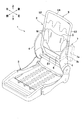
- the vehicle seat according to the present invention is configured by covering a seat cushion made of urethane foam or the like on the outside of a seat frame 1 as shown in FIG.
- the seat frame 1 includes a seat back frame 2 and a seating portion frame 3.
- front and rear, left and right, and top and bottom are based on a passenger sitting on the seat.
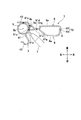
- the seat back frame 2 includes a pair of side frames 4, a reinforcing frame that reinforces the side frames 4, that is, a pipe frame 5, a lower frame 6, and a bracket 7 as an example of an input member.
- the pipe frame 5 has a cylindrical pipe shape (closed cross-sectional shape) and is formed by being bent into a substantially rectangular ring shape.
- the pipe frame 5 includes side portions 52 and 53 as examples of the left and right base frames, a lower portion 51 that connects the lower ends of the side portions 52 and 53, and an upper portion 54 that connects the upper ends of the side portions 52 and 53. have.
- the lower portion 51 of the pipe frame 5 (including a portion extending obliquely downward from the side frame 4) functions as a load transmitting portion that transmits a load in the left-right direction together with the lower frame 6.
- the side frame 4 is a plate-like member joined adjacent to the outer side in the left-right direction of the lower portion of the pipe frame 5 (each side portion 52, 53), together with each side portion 52, 53. It constitutes the left and right lower parts.
- the side frame 4 is formed so as to protrude forward (at least one in the front-rear direction) from the pipe frame 5.
- a forward projecting shape of the seat back side portion is formed, and components such as an airbag (not shown) can be satisfactorily fixed to the plate-like side frame 4 extending in the front-rear direction. ing.
- the side frame 4 is formed with a hole 41 penetrating left and right at an appropriate position, and the front portion 42 of the side frame 4 bends inward in the left-right direction, and then bends backward U It is bent in a letter shape. Thereby, the rigidity of the front part 42 of the side frame 4 is improved.
- the rear portion 43 of the side frame 4 is bent in an approximately L shape toward the inner side in the left-right direction and joined to the pipe frame 5 by welding.
- the points welded by the welding torch T are indicated by large black dots.
- the lower frame 6 is a plate-like member extending in the left-right direction, joined to and connected to the lower part of each side frame 4, and joined to the lower part 51 of the pipe frame 5.
- the load applied to the bracket 7 from the outside in the left-right direction is transmitted to the left-right opposite side of the bracket 7 via the lower frame 6 and the lower part 51 of the pipe frame 5 described above.
- the bracket 7 is a component configured separately from the pipe frame 5 and the side frame 4, and is adjacent to the left side (outside in the left-right direction) of the side portion 53 (one base frame) of the pipe frame 5 via the side frame 4. Is provided.
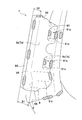
- the bracket 7 When the vehicle seat is attached to the vehicle, the bracket 7 has an input side end 7a (outer wall 73 (see FIG. 2)) on the outer side in the left-right direction close to a side panel such as a side pillar or door of the vehicle.
- the side impact load applied to the vehicle is input from the input side end 7a (the load is input from the outside in the left-right direction).
- the bracket 7 outputs (transmits) a load input from the input side end 7a to the side frame 4 and the pipe frame 5 from the output side end 7b on the inner side in the left-right direction.
- the bracket 7 is directly fixed to the pipe frame 5 by welding through two holes 41 (openings) formed in the side frame 4. Thereby, it is possible to transmit the load from the bracket 7 to the pipe frame 5 without being affected by the deformation of the side frame 4 regardless of the input angle or the magnitude of the side impact load. It has become.
- the welded portion is indicated by dot hatching.
- the bracket 7 is configured by fitting a front box-shaped member 8 and a rear box-shaped member 9 which are divided in the front-rear direction, and each box when cut by a plane orthogonal to the left-right direction.
- the closed members 8 and 9 form a closed cross-sectional shape.
- the front box-shaped member 8 includes a plate-like front wall 81 that extends longer in the vertical direction than the left-right direction, an upper wall 82 that extends rearward from the upper end of the front wall 81, and a rearward end from the laterally outer end of the front wall 81.
- An extending outer wall 83 and a lower wall 84 extending rearward from the lower end of the front wall 81 are integrally provided. That is, the front box-shaped member 8 is formed in a box shape that opens rearward and inward in the left-right direction.
- the front wall 81 is formed with two concave portions 81a (concave and convex shapes) that are recessed inward in the front-rear direction at portions away from the upper and lower ends of the front wall 81, and are arranged side by side at predetermined intervals. Thereby, since the rigidity of the front wall 81 is improved, it is possible to satisfactorily transmit the side impact load to the pipe frame 5 by the highly rigid front wall 81.
- each recessed part 81a is formed in the output side edge part 8b of the front wall 81, and is opened ahead and the left-right direction inner side.
- the edge 81c of the output side end 8b is bent back and forth, so that the rigidity of the output side edge 81c of the side impact load can be increased, and the side impact load can be transmitted to the pipe frame 5 and the like. It is possible.
- the inner wall 81g on the left side of each recess 81a is inclined rearward and rightward from the front surface of the input side end 8a of the front wall 81 toward the bottom wall 81d of the recess 81a.
- the front wall 81 has an inclined surface (inner wall 81g) inclined with respect to the left-right direction so as to gradually reduce the front-rear width of the bracket 7 from left to right.
- an extending portion 81 e (a part of the input member on the inner side in the left-right direction) is formed on the bottom wall 81 d of each recess 81 a, extending inward in the left-right direction with respect to the edge 81 c of the front wall 81. ing.
- the extending portion 81e extends to the pipe frame 5 through the hole 41 of the side frame 4 described above, and is welded in a state of being abutted against the pipe frame 5.
- the size of the hole 41 may be made to be a size corresponding to the extended portion 81e. 4 can be improved.
- the hole 41 is formed to be smaller than the front-rear width of the pipe frame 5, is smaller than the vertical length of the entire edge 81c of the front wall 81, and is higher than the extended portion 81e.
- the shape of the long hole is large.
- size of the hole 41 should just be the magnitude
- the hole 41 is formed in such a size, for example, the rigidity of the side frame 4 can be increased as compared with a case where a hole having a size that allows the entire end of the bracket 7 on the inner side in the left-right direction to pass therethrough is formed. It is possible.
- extension part 81e was provided, this invention is not limited to this, The extension part 81e does not need to be provided. In this case, there is a slight gap between the pipe frame 5 and the edge 81c of the front wall 81, but welding is possible even if such a gap is left, and the pipe frame 5 and the bracket 7 Can be fixed directly.
- the portion (including the extending portion 81 e) that becomes the edge of the bottom wall 81 d of the recess 81 a in the edge 81 c of the output side end portion 8 b is located within the front-rear width of the pipe frame 5.
- the extending part 81e is fixed to the central part 5a of the pipe frame 5 in the front-rear direction. Thereby, since the load from the bracket 7 is concentrated and transmitted to the center part 5a of the pipe frame 5, it is possible to transmit the load better.
- the center 5 b in the front-rear direction of the pipe frame 5 is located within the front-rear width of the bracket 7.
- the upper and lower portions of the edge 81c of the front wall 81 are fixed to the side frame 4 by welding. That is, the front wall 81 is directly fixed to both the side frame 4 and the pipe frame 5.
- the load input to the bracket 7 is transmitted not only to the pipe frame 5 but also to the load transmission part (the lower frame 6 and the lower part 51 of the pipe frame 5) not only through the side frame 4, but the load is further improved. It is possible to communicate to.
- the load transmitted to the load transmitting portion can be transmitted to the vehicle body side through a console box or the like provided on the side opposite to the bracket 7.
- the rear box-shaped member 9 includes a plate-shaped rear wall 91 that extends longer in the vertical direction than the left-right direction, an upper wall 92 that extends forward from the upper end of the rear wall 91, and the rear wall 91.
- An outer wall 93 extending forward from the outer end in the left-right direction and a lower wall 94 extending forward from the lower end of the rear wall 91 are integrally provided. That is, the rear box-shaped member 9 is formed in a box shape that opens forward and inward in the left-right direction.
- the rear wall 91 is formed with two concave portions 91a (concave and convex shapes) recessed inward in the front-rear direction at portions away from the upper and lower ends of the rear wall 91 so as to be lined up and down at predetermined intervals.
- the inner wall 91g on the left side of each recess 91a is inclined diagonally right forward from the rear surface of the input side end 9a of the rear wall 91 toward the bottom wall 91d of the recess 91a.
- the rear wall 91 has an inclined surface (inner wall 91g) inclined with respect to the left-right direction so as to gradually reduce the front-rear width of the bracket 7 from left to right.
- Each recess 91a is disposed so as to face the respective recesses 81a of the front box-like member 8 in the front-rear direction, and each bottom wall 91d and each bottom wall 81d of each recess 81a are disposed so as to contact each other. Yes. As a result, the two bottom walls 81d and 91d adjacent to each other form a thick portion at the substantially central portion of the bracket 7 in the front-rear direction, so that the side impact load can be transmitted well. Yes.
- bracket 7 The two bottom walls 81d and 91d adjacent to each other are joined by welding. Thereby, since the rigidity of bracket 7 can be raised, it is possible to transmit a side impact load satisfactorily.
- the two bottom walls 81d and 91d adjacent to each other are located within the front-rear width of the pipe frame 5. Thereby, it is possible to satisfactorily transmit the side impact load to the pipe frame 5 through the thickened portion by combining the two bottom walls 81d and 91d.
- the center 5b in the front-rear direction of the pipe frame 5 is located within the front-rear width of the thick portion including the bottom walls 81d and 91d.
- the load can be concentrated and transmitted to the vicinity of the center 5b of the pipe frame 5 through the thickened portion by combining the two bottom walls 81d and 91d.
- the edge 91c of the output side end portion 9b in the upper portion of the rear wall 91 is located within the longitudinal width of the pipe frame 5.
- the output side end portion 9b specifically, the edge 91c and the edge 81c of the front wall 81 (the portion serving as the edge of the bottom wall 81d) are positioned within the width of the pipe frame 5 (base frame) in the front-rear direction. It becomes.
- the input load is transmitted to the pipe frame 5 in a concentrated manner, it is possible to transmit the load satisfactorily.
- the output side end 9b of the rear wall 91 is fixed to the side frame 4 by welding. More specifically, as shown in FIG. 3, the output side end portion 9 b of the rear wall 91 is a closed cross section formed by the rear portion 43 of the side frame 4 bent in an L shape and the left rear portion of the pipe frame 5. It is joined to the shape part. As a result, the side impact load transmitted from the rear wall 91 to the inner side in the left-right direction is favorably received by the closed cross-sectional shape portion and is successfully transmitted to the pipe frame 5.
- the upper wall 92, the outer wall 93 and the lower wall 94 of the rear box-shaped member 9 are arranged so as to cover the upper wall 82, the outer wall 83 and the lower wall 84 of the front box-shaped member 8. These are fixed to the walls 82 to 84 by welding.
- the outer wall 73 of the bracket 7 is overlapped with the outer walls 83 and 93 (two plate-like portions) of the box-like members 8 and 9 at positions away from the front and rear ends.
- a step B (uneven shape) is formed by the alignment. Therefore, the substantially central portion of the outer wall 73 in the front-rear direction is formed thick by overlapping the outer walls 83 and 93, so that the rigidity of the outer wall 73 can be increased and the side impact load can be transmitted well. It has become.
- the upper wall 72 and the lower wall 74 of the bracket 7 have a step B (not shown) due to the overlapping of the upper walls 82 and 92 of the box-shaped members 8 and 9 and the lower walls 84 and 94. Is formed. That is, by fitting the rear box-shaped member 9 so as to cover the front-side box-shaped member 8, the upper wall 72, the outer wall 73, and the lower wall 74 of the bracket 7 are stepped B across the walls 72-74. It is formed continuously.
- the thick portion of the outer wall 73 is formed continuously with the thick portions of the upper wall 72 and the lower wall 74, so that the side impact load received by the thick portion of the outer wall 73 is continuously increased in the upper and lower thicknesses. It can be transmitted to the inside in the left-right direction through the thick part.
- the rear wall 91 is formed such that the lower end portion 91f bulges in a substantially mountain shape toward the rear.
- the front-back width D1 of a lower end part is larger than the front-back width D2 of an upper end part.
- each box-shaped member 8, 9 has an input side end portion 7 a (8 a and 9 a) whose diameter is increased in the vertical direction than the output side end portion 7 b (8 b and 9 b). is doing. More specifically, as shown in FIG. 5, the bracket 7 has a closed cross-sectional shape, and has a shape in which the left side (outside in the left-right direction) portions of the upper wall 72 and the lower wall 74 bulge upward or downward. ing.
- the bulged portion of the bracket 7, that is, the upper end portion (bulged portion 75) and the lower end portion (bulged portion 76) of the input side end portion 7 a are doubled in the left-right direction that is the load input direction. It becomes a wall structure.
- the rigidity of the bracket 7 can be improved, so that the deformation of the bracket 7 can be suppressed and the load can be transmitted well.
- the area of the input side end part 7a (outer wall 73) can be ensured by having the bulging parts 75 and 76, it is possible to receive a load reliably.
- Walls 75a, 76a (a part of the upper wall 72 and the lower wall 74) on the right side (in the left-right direction) of the bulging portions 75, 76 are directed from the upper end or lower end of the bulging portions 75, 76 toward the side frame 4 side.
- the bracket 7 has an inclined surface inclined with respect to the left-right direction so as to gradually reduce the vertical width.
- the bracket 7 Since the bracket 7 has a closed cross-sectional shape and the input side end 7a has a diameter larger than that of the output side end 7b, the rigidity of the bracket 7 can be improved. Thereby, since the deformation of the bracket 7 can be suppressed, the load can be favorably transmitted from the bracket 7 to the pipe frame 5 and the lower frame 6.
- the front-rear width D1 of the lower end portion of the input side end portion 7a is larger than the front-rear width D2 of the upper end portion, a load input area can be secured and the load can be transmitted better.
- load transmission is performed below via the load transmission member (the lower frame 6 and the lower portion 51 of the pipe frame 5), so by increasing the front-rear width D1 of the input side end portion 7a, Contributes to better transmission of load.
- the output side end portion 7b of the bracket 7 is positioned within the width of the pipe frame 5 in the front-rear direction, the input load can be concentrated on the pipe frame 5, and the load can be transmitted better.
- front wall 81 and the rear wall 91 of the bracket 7 have inclined surfaces (inner walls 81g, 91g) inclined with respect to the left-right direction so as to gradually reduce the front-rear width of the bracket 7, deformation of the bracket 7 can be suppressed, Can be transmitted better.
- bracket 7 Since the upper wall 72 and the lower wall 74 of the bracket 7 have inclined surfaces (walls 75a, 76a) that are inclined with respect to the left-right direction so as to gradually reduce the vertical width of the bracket 7, deformation of the bracket 7 can be suppressed, and the load Can be transmitted better.
- bracket 7 Since the bracket 7 is directly fixed to the pipe frame 5 instead of the side frame 4, the load is not affected by the deformation of the side frame 4 regardless of the input angle or size of the side impact load. Can be satisfactorily transmitted from the bracket 7 to the pipe frame 5.
- bracket 7 is configured separately from the pipe frame 5, each can be formed into a free shape and the assemblability can be improved.
- bracket 7 and the pipe frame 5 By fixing the bracket 7 and the pipe frame 5 through the opening (hole 41) formed in the side frame 4, for example, it is not necessary to divide the side frame back and forth or up and down so as to avoid the fixing part of the bracket and the pipe frame.
- the rigidity of the side frame 4 can be improved.
- the bracket 7 Since only a part of the bracket 7 (the extended portion 81e) is fixed to the pipe frame 5 through the opening (hole 41), it is not necessary to form an opening in the side frame so as to pass through the entire side part on the inner side in the left-right direction of the bracket. Therefore, the rigidity of the side frame 4 can be further improved.
- the opening formed in the side frame 4 is the hole 41, for example, the bracket 7 and the pipe frame 5 in the side frame 4 are fixed compared to a structure in which the opening is formed in a groove shape (notch shape) opened forward or backward. Since the upper part and the lower part can be connected before and after the fixed part, the rigidity of the side frame 4 can be further improved.
- bracket 7 Since the bracket 7 is fixed to the pipe frame 5 having a closed cross-sectional shape, the load from the bracket 7 is satisfactorily applied to the load transmission part (the lower frame 6 and the lower part 51 of the pipe frame 5) via the pipe frame 5 that is difficult to deform. Can communicate.
- bracket 7 Since the bracket 7 is directly fixed to both the side frame 4 and the pipe frame 5, the load input to the bracket 7 is transmitted not only to the pipe frame 5 but also to the load transmission portion via the side frame 4. The load can be transmitted better.
- bracket 7 Since the bracket 7 is fixed to the central portion 5a in the front-rear direction of the pipe frame 5, the load from the bracket 7 is concentrated and transmitted to the central portion 5a in the front-rear direction of the pipe frame 5, so that the load is transmitted better. Can do.
- the base frame (side portions 52 and 53 of the pipe frame 5) has a cylindrical pipe shape.
- the present invention is not limited to this, and for example, a polygonal pipe shape may be used.
- a polygonal columnar member may be employed.
- the input member is the bracket 7 composed of the two box-like members 8 and 9, but the present invention is not limited to this, and for example, a bracket constituted by one box-like member may be used.
- the load transmitting portion is configured by the lower frame 6 and the lower portion 51 of the pipe frame 5, but the present invention is not limited to this.
- the load transmitting portion (lower part 51) is integrally formed with the pipe frame 5 which is the base frame.
- each pipe frame 5 A separate frame connecting the lower end portions may be used as the load transmitting portion.
- the lower part 51 of the pipe frame 5 in the above embodiment is divided in the middle and joined to the lower frame 6, the lower part 51 and the lower frame 6 that extend partway may be used as the load transmitting portion.
- the bracket 7 and the pipe frame 5 were fixed by welding, this invention is not limited to this, For example, you may fix with a volt
- the hole 41 is employed as the opening.
- the present invention is not limited to this, and may be, for example, a notch opening forward or backward.
- a part of the bracket 7 (the extended portion 81e) is passed through the opening (hole 41).
- the present invention is not limited to this, and a part of the base frame is passed through the opening and fixed directly to the bracket. May be.
- the bracket 7 was directly fixed to the pipe frame 5, this invention is not limited to this, For example, you may fix only to the side frame of the said embodiment.
- the seat back frame 2 includes the side frame 4, but the present invention is not limited to this, and may have a configuration not including the side frame, for example.
- the entire base frame (pipe frame 5) has a closed cross-sectional shape, but the present invention is not limited to this, and at least a portion of the base frame to which the input member is fixed may have a closed cross-sectional shape. That's fine.
- the front wall 81 and the rear wall 91 of the bracket 7 have inclined surfaces (inner walls 81g, 91g) inclined with respect to the left-right direction so that the front-rear width of the bracket 7 is gradually reduced.
- the invention is not limited to this.
- only one of the front wall 81 and the rear wall 91 may have an inclined surface, or both may not have an inclined surface.
- the upper wall 72 and the lower wall 74 of the bracket 7 have inclined surfaces (walls 75a and 76a) inclined with respect to the left-right direction so that the vertical width of the bracket 7 is gradually reduced.
- the present invention is not limited to this.
- only one of the upper wall 72 and the lower wall 74 may have an inclined surface, or both may not have an inclined surface.
- the output side end portion 8b of the front wall 81 is located within the width of the pipe frame 5 in the front-rear direction, only a part of the edge 81c (the portion that becomes the edge of the bottom wall 81d).
- the present invention is not limited to this.
- the entire edge of the output side end may be positioned within the width of the pipe frame 5.
- the front-rear width D1 of the lower end portion of the bracket 7 is larger than the front-rear width D2 of the upper end portion, but the present invention is not limited to this.
- the front-rear width of the lower end portion of the input member and the front-rear width of the upper end portion may be the same.
- the front-rear width of the lower end part may be made larger than the front-rear width of the upper end part only at the input side end part.
- the input side end 7a of the bracket 7 has a diameter larger than that of the output side end 7b.
- the present invention is not limited to this, and for example, the input side of the input member
- the end portion may be expanded in diameter before and after the output side end portion.
- the input side end of the input member may have a diameter that is larger in the vertical direction and the front and rear direction than the output side end.
Abstract
Description
本発明に係る車両用シートは、図1に示すようなシートフレーム1の外側に、ウレタンフォームなどからなるシートクッションを被せることで構成されている。シートフレーム1は、シートバックフレーム2と、着座部フレーム3を有する。なお、本発明において、前後、左右、上下は、シートに座る乗員を基準とする。
ブラケット7が閉断面形状を有し、入力側端部7aが出力側端部7bよりも上下に拡径しているので、ブラケット7の剛性を向上させることができる。これにより、ブラケット7の変形を抑制することができるので、荷重をブラケット7からパイプフレーム5およびロアフレーム6に良好に伝達することができる。
前記実施形態では、ベースフレーム(パイプフレーム5の側部52,53)を円筒状のパイプ形状としたが、本発明はこれに限定されず、例えば多角形状のパイプ形状としてもよいし、円柱や多角柱状の部材を採用してもよい。
前記実施形態では、開口として孔41を採用したが、本発明はこれに限定されず、例えば前方または後方に開口する切欠などであってもよい。
前記実施形態では、シートバックフレーム2がサイドフレーム4を備えていたが、本発明はこれに限定されず、例えばサイドフレームを備えない構成としてもよい。
Claims (5)
- シートバックフレームの左右少なくとも下側部分を構成する左右のベースフレームと、
一方のベースフレームの左右方向外側に隣接して設けられ、左右方向外側から荷重が入力される入力部材と、
前記入力部材からの荷重を前記入力部材が設けられている側とは左右反対側に伝達する荷重伝達部と、を備え、
前記入力部材は、閉断面形状を有するととともに、入力側端部が出力側端部よりも上・下・前・後の方向のうち少なくとも一方向に拡径していることを特徴とする車両用シート。 - 前記入力側端部は、下端部の前後幅が上端部の前後幅よりも大きいことを特徴とする請求項1に記載の車両用シート。
- 前記ベースフレームは、パイプ形状を有し、
前記入力部材の出力側端部は、前後方向において前記ベースフレームの幅内に位置することを特徴とする請求項1に記載の車両用シート。 - 前記入力部材は、前後の壁の少なくとも一部が、前記入力部材の前後幅を徐々に小さくするように、左右方向に対し傾いた傾斜面を有していることを特徴とする請求項1に記載の車両用シート。
- 前記入力部材は、上下の壁の少なくとも一部が、前記入力部材の上下幅を徐々に小さくするように、左右方向に対し傾いた傾斜面を有していることを特徴とする請求項1に記載の車両用シート。
Priority Applications (4)
| Application Number | Priority Date | Filing Date | Title |
|---|---|---|---|
| US13/808,851 US9102253B2 (en) | 2010-07-09 | 2011-07-06 | Vehicle seat |
| CN201180033846XA CN103003099A (zh) | 2010-07-09 | 2011-07-06 | 车辆座椅 |
| JP2012523897A JP5805638B2 (ja) | 2010-07-09 | 2011-07-06 | 車両用シート |
| EP11803617.7A EP2591950A4 (en) | 2010-07-09 | 2011-07-06 | VEHICLE SEAT |
Applications Claiming Priority (2)
| Application Number | Priority Date | Filing Date | Title |
|---|---|---|---|
| JP2010157271 | 2010-07-09 | ||
| JP2010-157271 | 2010-07-09 |
Publications (1)
| Publication Number | Publication Date |
|---|---|
| WO2012005283A1 true WO2012005283A1 (ja) | 2012-01-12 |
Family
ID=45441260
Family Applications (1)
| Application Number | Title | Priority Date | Filing Date |
|---|---|---|---|
| PCT/JP2011/065444 WO2012005283A1 (ja) | 2010-07-09 | 2011-07-06 | 車両用シート |
Country Status (5)
| Country | Link |
|---|---|
| US (1) | US9102253B2 (ja) |
| EP (1) | EP2591950A4 (ja) |
| JP (1) | JP5805638B2 (ja) |
| CN (1) | CN103003099A (ja) |
| WO (1) | WO2012005283A1 (ja) |
Families Citing this family (5)
| Publication number | Priority date | Publication date | Assignee | Title |
|---|---|---|---|---|
| US9102251B2 (en) | 2010-07-09 | 2015-08-11 | Ts Tech Co., Ltd. | Vehicle seat |
| CN103003098A (zh) | 2010-07-09 | 2013-03-27 | 提爱思科技股份有限公司 | 车辆座椅 |
| CN110461646B (zh) | 2017-03-27 | 2022-04-19 | 提爱思科技股份有限公司 | 乘坐物用座椅 |
| JP2018192934A (ja) * | 2017-05-18 | 2018-12-06 | トヨタ紡織株式会社 | 乗物用シートのバックフレーム |
| US11279488B2 (en) * | 2020-02-20 | 2022-03-22 | B/E Aerospace, Inc. | Seat assembly with sacrificial backrest breakover feature |
Citations (3)
| Publication number | Priority date | Publication date | Assignee | Title |
|---|---|---|---|---|
| JPH11222088A (ja) | 1998-02-10 | 1999-08-17 | Honda Motor Co Ltd | 車両における側面衝突保護装置 |
| JP2001105947A (ja) * | 1999-10-14 | 2001-04-17 | Nissan Motor Co Ltd | 車体構造 |
| WO2009044729A1 (ja) * | 2007-10-02 | 2009-04-09 | Toyota Shatai Kabushiki Kaisha | 自動車のボディ構造 |
Family Cites Families (26)
| Publication number | Priority date | Publication date | Assignee | Title |
|---|---|---|---|---|
| JPH057956Y2 (ja) * | 1987-11-27 | 1993-03-01 | ||
| GB2283163A (en) | 1993-10-26 | 1995-05-03 | Autoliv Dev | "Improvements in or relating to a vehicle seat" |
| JP3011231B2 (ja) | 1995-12-20 | 2000-02-21 | 池田物産株式会社 | 車両用シート |
| JP3583556B2 (ja) | 1996-08-06 | 2004-11-04 | ジョンソン コントロールズ オートモーティブ システムズ株式会社 | 自動車用座席 |
| JP2000103275A (ja) | 1998-09-30 | 2000-04-11 | Fuji Heavy Ind Ltd | 自動車用シート |
| EP0990553B1 (en) | 1998-09-30 | 2006-03-08 | Fuji Jukogyo Kabushiki Kaisha | Vehicle seat with occupant protection devices |
| US6857698B2 (en) * | 2003-02-21 | 2005-02-22 | Lear Corporation | Seat side impact resistance mechanism |
| DE102005051948B4 (de) * | 2005-10-29 | 2007-12-06 | Dr.Ing.H.C. F. Porsche Ag | Vorrichtung zur Aufnahme von Seitenkräften bei einem Seitenaufprall eines Kraftfahrzeugs |
| JP2007253887A (ja) | 2006-03-24 | 2007-10-04 | Press Kogyo Co Ltd | 車枠の継ぎ手 |
| EP1857320B1 (en) | 2006-05-20 | 2010-10-13 | Jian-Jhong Fong | Safety seat system for car |
| JP4752629B2 (ja) | 2006-06-07 | 2011-08-17 | 日産自動車株式会社 | 自動車の側突荷重伝達構造 |
| JP4405546B2 (ja) * | 2007-07-20 | 2010-01-27 | 本田技研工業株式会社 | 車両用シート |
| US8033602B2 (en) | 2007-07-20 | 2011-10-11 | Honda Motor Co., Ltd. | Vehicle seat |
| US7631926B2 (en) * | 2007-10-02 | 2009-12-15 | Honda Motor Co., Ltd. | Side impact crash event body structure improvement |
| JP5182478B2 (ja) * | 2007-10-12 | 2013-04-17 | 日産自動車株式会社 | 車体の側突荷重支持構造および側突荷重支持方法 |
| JP5308011B2 (ja) | 2007-11-21 | 2013-10-09 | テイ・エス テック株式会社 | 車両用シート |
| JP5237673B2 (ja) | 2008-04-08 | 2013-07-17 | 本田技研工業株式会社 | 車体前部構造 |
| JP4485582B2 (ja) * | 2008-07-11 | 2010-06-23 | 本田技研工業株式会社 | 車両の荷重伝達体 |
| JP5292004B2 (ja) * | 2008-07-11 | 2013-09-18 | 本田技研工業株式会社 | 車両用シート |
| JP4738506B2 (ja) | 2009-03-26 | 2011-08-03 | 本田技研工業株式会社 | 補強体構造 |
| JP5562590B2 (ja) | 2009-07-25 | 2014-07-30 | 株式会社タチエス | 自動車シート |
| US8292353B2 (en) * | 2009-12-01 | 2012-10-23 | Toyota Motor Engineering & Manufacturing North America, Inc. | Construction for an automotive vehicle |
| CN103003098A (zh) | 2010-07-09 | 2013-03-27 | 提爱思科技股份有限公司 | 车辆座椅 |
| US9102251B2 (en) | 2010-07-09 | 2015-08-11 | Ts Tech Co., Ltd. | Vehicle seat |
| EP2599662A4 (en) | 2010-07-09 | 2016-04-27 | Ts Tech Co Ltd | VEHICLE SEAT |
| US9010855B2 (en) * | 2010-09-17 | 2015-04-21 | Honda Motor Co., Ltd. | Vehicle seat |
-
2011
- 2011-07-06 WO PCT/JP2011/065444 patent/WO2012005283A1/ja active Application Filing
- 2011-07-06 JP JP2012523897A patent/JP5805638B2/ja active Active
- 2011-07-06 EP EP11803617.7A patent/EP2591950A4/en not_active Withdrawn
- 2011-07-06 US US13/808,851 patent/US9102253B2/en not_active Expired - Fee Related
- 2011-07-06 CN CN201180033846XA patent/CN103003099A/zh active Pending
Patent Citations (3)
| Publication number | Priority date | Publication date | Assignee | Title |
|---|---|---|---|---|
| JPH11222088A (ja) | 1998-02-10 | 1999-08-17 | Honda Motor Co Ltd | 車両における側面衝突保護装置 |
| JP2001105947A (ja) * | 1999-10-14 | 2001-04-17 | Nissan Motor Co Ltd | 車体構造 |
| WO2009044729A1 (ja) * | 2007-10-02 | 2009-04-09 | Toyota Shatai Kabushiki Kaisha | 自動車のボディ構造 |
Non-Patent Citations (1)
| Title |
|---|
| See also references of EP2591950A4 |
Also Published As
| Publication number | Publication date |
|---|---|
| US20130113243A1 (en) | 2013-05-09 |
| CN103003099A (zh) | 2013-03-27 |
| JPWO2012005283A1 (ja) | 2013-09-05 |
| US9102253B2 (en) | 2015-08-11 |
| EP2591950A1 (en) | 2013-05-15 |
| EP2591950A4 (en) | 2016-04-27 |
| JP5805638B2 (ja) | 2015-11-04 |
Similar Documents
| Publication | Publication Date | Title |
|---|---|---|
| WO2012005279A1 (ja) | 車両用シート | |
| WO2012005280A1 (ja) | 車両用シート | |
| WO2012005298A1 (ja) | 車両用シート | |
| JP5805637B2 (ja) | 車両用シート | |
| JP4738506B2 (ja) | 補強体構造 | |
| JP5275622B2 (ja) | 車両用シート | |
| WO2010100717A1 (ja) | 車両の骨格構造 | |
| WO2012005283A1 (ja) | 車両用シート | |
| WO2012005281A1 (ja) | 車両用シート | |
| JP5563393B2 (ja) | 車両用シート | |
| JP2005001473A (ja) | 自動車の下部車体構造 | |
| JPWO2013161611A1 (ja) | 対側突荷重伝達構造 | |
| JP5572461B2 (ja) | 車両用シート | |
| JP5572462B2 (ja) | 車両用シート | |
| JP6353566B2 (ja) | 車両用シート | |
| JP5820907B2 (ja) | 車両用シート | |
| JP6092339B2 (ja) | 車両用シート | |
| JP5572463B2 (ja) | 車両用シート | |
| JP6335109B2 (ja) | 側面衝突用補強部材を備えた乗用車シート | |
| JP7040380B2 (ja) | 車両の後部車体構造 |
Legal Events
| Date | Code | Title | Description |
|---|---|---|---|
| 121 | Ep: the epo has been informed by wipo that ep was designated in this application |
Ref document number: 11803617 Country of ref document: EP Kind code of ref document: A1 |
|
| WWE | Wipo information: entry into national phase |
Ref document number: 2012523897 Country of ref document: JP |
|
| WWE | Wipo information: entry into national phase |
Ref document number: 13808851 Country of ref document: US |
|
| REEP | Request for entry into the european phase |
Ref document number: 2011803617 Country of ref document: EP |
|
| WWE | Wipo information: entry into national phase |
Ref document number: 2011803617 Country of ref document: EP |
|
| NENP | Non-entry into the national phase |
Ref country code: DE |