WO2012005258A1 - 絶縁電線の接続構造及び接続方法 - Google Patents
絶縁電線の接続構造及び接続方法 Download PDFInfo
- Publication number
- WO2012005258A1 WO2012005258A1 PCT/JP2011/065392 JP2011065392W WO2012005258A1 WO 2012005258 A1 WO2012005258 A1 WO 2012005258A1 JP 2011065392 W JP2011065392 W JP 2011065392W WO 2012005258 A1 WO2012005258 A1 WO 2012005258A1
- Authority
- WO
- WIPO (PCT)
- Prior art keywords
- conductor
- portions
- wires
- folded
- electric wires
- Prior art date
- Legal status (The legal status is an assumption and is not a legal conclusion. Google has not performed a legal analysis and makes no representation as to the accuracy of the status listed.)
- Ceased
Links
Images






Classifications
-
- H—ELECTRICITY
- H01—ELECTRIC ELEMENTS
- H01B—CABLES; CONDUCTORS; INSULATORS; SELECTION OF MATERIALS FOR THEIR CONDUCTIVE, INSULATING OR DIELECTRIC PROPERTIES
- H01B13/00—Apparatus or processes specially adapted for manufacturing conductors or cables
-
- H—ELECTRICITY
- H01—ELECTRIC ELEMENTS
- H01B—CABLES; CONDUCTORS; INSULATORS; SELECTION OF MATERIALS FOR THEIR CONDUCTIVE, INSULATING OR DIELECTRIC PROPERTIES
- H01B7/00—Insulated conductors or cables characterised by their form
- H01B7/0009—Details relating to the conductive cores
-
- H—ELECTRICITY
- H01—ELECTRIC ELEMENTS
- H01R—ELECTRICALLY-CONDUCTIVE CONNECTIONS; STRUCTURAL ASSOCIATIONS OF A PLURALITY OF MUTUALLY-INSULATED ELECTRICAL CONNECTING ELEMENTS; COUPLING DEVICES; CURRENT COLLECTORS
- H01R4/00—Electrically-conductive connections between two or more conductive members in direct contact, i.e. touching one another; Means for effecting or maintaining such contact; Electrically-conductive connections having two or more spaced connecting locations for conductors and using contact members penetrating insulation
- H01R4/02—Soldered or welded connections
-
- H—ELECTRICITY
- H01—ELECTRIC ELEMENTS
- H01R—ELECTRICALLY-CONDUCTIVE CONNECTIONS; STRUCTURAL ASSOCIATIONS OF A PLURALITY OF MUTUALLY-INSULATED ELECTRICAL CONNECTING ELEMENTS; COUPLING DEVICES; CURRENT COLLECTORS
- H01R4/00—Electrically-conductive connections between two or more conductive members in direct contact, i.e. touching one another; Means for effecting or maintaining such contact; Electrically-conductive connections having two or more spaced connecting locations for conductors and using contact members penetrating insulation
- H01R4/02—Soldered or welded connections
- H01R4/021—Soldered or welded connections between two or more cables or wires
-
- H—ELECTRICITY
- H01—ELECTRIC ELEMENTS
- H01R—ELECTRICALLY-CONDUCTIVE CONNECTIONS; STRUCTURAL ASSOCIATIONS OF A PLURALITY OF MUTUALLY-INSULATED ELECTRICAL CONNECTING ELEMENTS; COUPLING DEVICES; CURRENT COLLECTORS
- H01R4/00—Electrically-conductive connections between two or more conductive members in direct contact, i.e. touching one another; Means for effecting or maintaining such contact; Electrically-conductive connections having two or more spaced connecting locations for conductors and using contact members penetrating insulation
- H01R4/10—Electrically-conductive connections between two or more conductive members in direct contact, i.e. touching one another; Means for effecting or maintaining such contact; Electrically-conductive connections having two or more spaced connecting locations for conductors and using contact members penetrating insulation effected solely by twisting, wrapping, bending, crimping, or other permanent deformation
- H01R4/12—Electrically-conductive connections between two or more conductive members in direct contact, i.e. touching one another; Means for effecting or maintaining such contact; Electrically-conductive connections having two or more spaced connecting locations for conductors and using contact members penetrating insulation effected solely by twisting, wrapping, bending, crimping, or other permanent deformation by twisting
-
- H—ELECTRICITY
- H01—ELECTRIC ELEMENTS
- H01R—ELECTRICALLY-CONDUCTIVE CONNECTIONS; STRUCTURAL ASSOCIATIONS OF A PLURALITY OF MUTUALLY-INSULATED ELECTRICAL CONNECTING ELEMENTS; COUPLING DEVICES; CURRENT COLLECTORS
- H01R43/00—Apparatus or processes specially adapted for manufacturing, assembling, maintaining, or repairing of line connectors or current collectors or for joining electric conductors
- H01R43/02—Apparatus or processes specially adapted for manufacturing, assembling, maintaining, or repairing of line connectors or current collectors or for joining electric conductors for soldered or welded connections
-
- H—ELECTRICITY
- H01—ELECTRIC ELEMENTS
- H01R—ELECTRICALLY-CONDUCTIVE CONNECTIONS; STRUCTURAL ASSOCIATIONS OF A PLURALITY OF MUTUALLY-INSULATED ELECTRICAL CONNECTING ELEMENTS; COUPLING DEVICES; CURRENT COLLECTORS
- H01R43/00—Apparatus or processes specially adapted for manufacturing, assembling, maintaining, or repairing of line connectors or current collectors or for joining electric conductors
- H01R43/02—Apparatus or processes specially adapted for manufacturing, assembling, maintaining, or repairing of line connectors or current collectors or for joining electric conductors for soldered or welded connections
- H01R43/0207—Ultrasonic-, H.F.-, cold- or impact welding
Definitions
- the present invention relates to a connection structure and a connection method for an insulated wire in which a plurality of insulated wires are twisted together and electrically connected together.
- connection method described in Patent Document 1 has an inlet 101 having a certain extent in a cylindrical object and two holes 102 having a certain angle, and a rotating shaft 103.
- the two cords are inserted into the holes and then the rotating shaft is rotated. Thereby, two cords are simultaneously rotated, twisted, and connected.
- connection method described in Patent Document 2 is a method of performing an interconnecting spiral torsion connection between two wires 203 and 204 as shown in FIG.
- the two members 201 and 202 of the two-member connector are mutually rotated.
- the cavity means has such a shape that the wires 203 and 204 can be introduced only in a side-by-side relationship with the cavity means when the wires 203 and 204 are in a specific direction with respect to the cavity means.
- the wires 203 and 204 are jammed with respect to the inner surface.
- reference numerals 203A and 204A denote storage portions in the connector.
- ultrasonic bonding may be employed from the viewpoint of easy and reliable work.
- the portions where the insulating coatings of the plurality of insulated wires 301 to 304 are stripped and the conductors 301A to 304A are exposed are simply arranged in parallel (parallel
- the conductors 301A to 304A are connected to each other by applying ultrasonic bonding to the portions arranged in parallel.
- connection strength there is a problem in connection strength. Specifically, there is a problem that the conductor is partially broken due to insufficient connection strength.
- this insulated wire connection method is performed by applying insulation coating on a plurality of insulated wires 401 to 404 as shown in FIGS. 14 (A), 14 (B), 15 (A), and 15 (B).
- Each of the conductors 401A to 404A is exposed by stripping off a predetermined length, the exposed conductors 401A to 404A are twisted together in the same direction, and the twisted portions are welded and connected by ultrasonic bonding. Is.
- the plurality of insulated wires 401 to 404 are electrically connected, sufficient connection strength can be ensured even if the conductors 401A to 404A are connected by ultrasonic bonding.
- Patent Document 1 has such inconveniences that it is difficult to twist the cords well if the cords are hard in material or the number of cords is large.
- Patent Document 2 has inconveniences such as difficult connection with a twisted wire. It is also necessary to take measures such as preparing connectors according to the number and diameter of cords.
- the present invention has been made in view of the circumstances described above, and its purpose is to reduce the number of wires to be connected while minimizing damage to the conductors when twisting the conductors of the respective conductors to be connected together.
- An object of the present invention is to provide an insulated wire connection structure and connection method capable of minimizing damage to a conductor even when there are many conductors or when a conductor cross-sectional area is large.
- the insulated wire connection structure according to the present invention is characterized by the following (1).
- (1) A connection structure of insulated wires in which conductor portions of each of a plurality of electric wires exposed by removing a part of the covering are twisted together and ultrasonically joined together, In a state where the covering portions on both sides sandwiching the exposed conductor portion overlap each other, a combined covering portion in which the covering portions of each of the plurality of electric wires are bundled, A joint conductor in which the conductor portions of each of the plurality of electric wires are twisted in a state where the exposed conductor portion is folded, and the other portions except the folded portion of the conductor portion are integrally ultrasonically bonded. And Be provided.
- the insulated wire connection structure described in (1) above when the conductor portions of the respective conductors to be connected are twisted together, damage to the conductor is suppressed as much as possible, and the number of wires to be connected is large. Even if the conductor cross-sectional area is large, it is possible to provide an insulated wire connection structure that can minimize damage to the conductor.
- the insulated wire connection method according to the present invention is characterized by the following (2) to (4).
- a rotating jig is inserted inside the folded portions of the conductor portions of each of the plurality of electric wires, and the conductor portions are rotated by rotating the rotating jig.
- twist together Twist together.
- (4) In the method for connecting insulated wires according to (2) or (3) above, Further comprising a step of processing the twisted conductor portion into a predetermined shape using a forming jig, In the step of ultrasonic bonding, the other portions excluding the folded portion of the conductor portion processed into a predetermined shape are integrally ultrasonically bonded.
- the method for connecting insulated wires described in (2) above when the conductor portions of the respective conductive wires to be connected are twisted together, damage to the conductor is suppressed as much as possible, and the number of electric wires to be connected is large. Even if the conductor cross-sectional area is large, it is possible to provide a method for connecting an insulated wire that can minimize damage to the conductor. According to the method for connecting insulated wires described in (3) above, the conductors can be easily twisted together by the rotating jig. According to the method for connecting insulated wires described in (4) above, ultrasonic bonding can be effectively performed.
- connection structure of the insulated wire of the present invention when the conductor portions of the conductors to be connected are twisted together, damage to the conductor is suppressed as much as possible, and when the number of wires to be connected is large or the conductor cross-sectional area Even if this is large, damage to the conductor can be minimized.
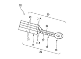
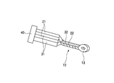
- FIG. 1 is a perspective view showing an insulated wire connection structure to which an insulated wire connection method according to an embodiment of the present invention is applied.
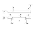
- 2 (A) and 2 (B) are diagrams showing one of the wires used in the insulated wire connection structure according to the embodiment of the present invention, and FIG. 2 (A) shows the insulated wire connection structure.
- One electric wire used, FIG. 2 (B), is an explanatory view showing a state where the coating is peeled off.
- 3 (A) and 3 (B) are diagrams showing the other electric wire used in the insulated wire connection structure according to the embodiment of the present invention, and FIG. 3 (A) shows the insulated wire connection structure.
- FIG. 3B is an explanatory view showing a state where the coating is peeled off.
- FIG. 4 is a process diagram showing one process of the connection method of the connection structure of the insulated wires.
- FIG. 5 is a process diagram showing one process of the connection method of the insulated wire connection structure.
- FIG. 6 is a process diagram showing one process of the connection method of the insulated wire connection structure.
- FIG. 7 is a process diagram showing one process of the connection method of the insulated wire connection structure.
- FIG. 8 is a process diagram showing one process of the connection method of the insulated wire connection structure.
- FIG. 9 is a process diagram showing one process of the connection method of the insulated wire connection structure.
- FIG. 10 is a process diagram showing a twisting process performed using a rotating jig different from the rotating jig shown in FIG. 4.
- FIG. 11 is a cross-sectional view showing a tool for electrically connecting conventional insulated wires by electrically twisting them together.
- FIG. 12 is a perspective view showing a method of twisting cables using another conventional connection tool.
- 13 (A) to 13 (D) are explanatory views showing still another conventional method of twisting electric wires.
- FIGS. 13 (A) to 13 (D) are diagrams illustrating one of the methods. It is a figure which shows a process.
- 14 (A) and 14 (B) are explanatory views showing still another conventional wire twisting method.
- FIGS. 14 (A) and 14 (B) show the state before twisting.
- FIGS. 14 (A) and 14 (B) are diagrams showing a state in the middle of twisting in the conventional wire twisting method shown in FIGS. 14 (A) and 14 (B).
- FIGS. 14 (A) and 14 (B) are a front view and a side view.
- FIG. 1 shows an insulated wire connection structure 10 according to an embodiment of the present invention.
- the insulated wire connection structure 10 includes a plurality of wires to be twisted (two in this embodiment, particularly 2).
- the conductors (not limited to the book), which are located at the intermediate portions of the electric wires 20 and 30, are peeled off by a predetermined length, removed, and exposed to conductors (hereinafter referred to as conductor portions; FIG. 2A). 2 (B), FIG. 3 (A), and FIG. 3 (B).) 22 and 32 are twisted together and integrally ultrasonically bonded.
- a portion 12 and a loop conductor portion 13 are provided.
- Each of the covering portions 11 is a state in which the covering portions 21 (31) on both sides sandwiching the exposed conductor portion 22 (32) overlap each other among the respective coverings of the electric wires 20 (30) to be connected, In this configuration, the covering portions 21 and 31 of the plurality of electric wires 20 and 30 are bundled.
- each of the conductor portions 22 and 32 is folded back into two at the center folding point, and the other electric wires 20 (30) are folded back with the exposed conductor portions 22 and 32 folded back.
- the conductor portions 22 (32) are twisted together and the conductor portions 22 and 32 other than the folded back portions (loop conductor portions 13 described later) are integrally ultrasonically joined together. ing.
- the loop conductor portion 13 is formed by integrally forming the tips of the joint conductor portions 12 of the electric wires 20 (30) that are integrated with each other in a loop shape. In this embodiment, the loop conductor portion 13 is left. However, the joint conductor portion 12 cannot be unwound after the junction conductor portion 12 is formed. Also good.
- a method for forming the insulated wire connection structure 10 according to the present embodiment will be described with reference to FIGS.
- a plurality (two in this embodiment) of electric wires 20 and 30 to be twisted are prepared (see FIG. 2A and FIG. 3A), and the respective coverings of the electric wires 20 and 30 are predetermined.
- the conductor portions 22 and 32 are exposed by a predetermined length (L) by peeling and removing only the length (L) (see FIGS. 2B and 3B).
- the edge portions on both sides of the covering portions 21 and 31 on both sides sandwiching the conductor portions 22 and 32 in each electric wire are referred to as “conductor adjacent edge portion 21A (31A)”.
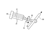
- each electric wire 20, 30 is bent in two with the intermediate portion (L / 2) of each conductor portion 22, 32 exposed by a predetermined length (L) as a reference point, 30 conductor portions 22 and 32 are formed in a loop shape (see FIG. 4).
- the “loop shape” here refers to a state in which the gap is minimized, in other words, a state having a slit-like hole S (see FIG. 4).
- the folded covering portions 21 and 31 of the electric wires 20 and 30 are collectively fixed and held together by a holding jig 40, and the conductor portions 22 and 32 of the electric wires 20 and 30.
- the through part 50 of the rotating jig is passed through the inside of the hole S of the folded part Q formed by folding in a loop shape.
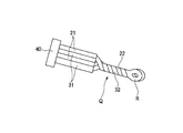
- the folded portions Q which are the conductor portions 22 and 32 of the electric wires 20 and 30 are twisted and twisted together, and finally all regions other than the portion where the penetrating portion 50 is left are twisted together.
- the hole S is narrowed by pushing the hole S of the folded portion Q toward the tip, and the ring portion R is formed by pulling out the through portion 50 of the rotating jig from the hole S (see FIG. 6). ).
- the folded portion Q which is the conductor portions 22 and 32 of the electric wires 20 and 30, is pressed and processed into a predetermined shape using a pair of upper and lower forming jigs 60, as shown in FIG. Although it is not essential to perform this processing, ultrasonic bonding described later can be effectively performed.
- the folded portion Q that has been twisted and processed in this way is pressurized using the anvil 71 and the horn 72 (white arrow in FIG. 8) and vibrated ( (Solid arrows in FIG. 8) are ultrasonically joined.
- turning part Q is formed.
- the conductor portions 22 and 32 are connected. It will not be able to be solved naturally. Therefore, although it may be cut off, in this embodiment, it is left as it is as the loop conductor portion 13 as shown in FIG.
- the conductor edge portion 21A (31A) in particular in the covering portions 21 and 31 of the electric wires 20 and 30 is finally obtained.
- the holding jig 40 that has been fixed and held together near the conductor edge 21A (31A) can be finally removed.
- the folded portions Q that are the conductor portions 22 and 32 of the electric wires 20 and 30 are integrally twisted and twisted by the through portion 50 of the rotating jig.
- a rotating jig 50 ′ as shown in FIG. 10 may be used together with the holding jig 40 to twist the folded portion Q integrally.
- the conductor portion is hung on the holding jig, so that the conductor damage received when the conductor portions 22 and 32 are held is very small. Therefore, when forming the connection structure 10 of the present invention by twisting, the connection structure method of the present invention can be applied even when the number of electric wires is large or the conductor electric area is large.
- connection structure of the insulated wire of the present invention when the conductor portions of the conductors to be connected are twisted together, damage to the conductor is suppressed as much as possible, and when the number of wires to be connected is large or the conductor cross-sectional area Even if it is large, there is an effect that damage to the conductor can be minimized.
Landscapes
- Engineering & Computer Science (AREA)
- Manufacturing & Machinery (AREA)
- Connections Effected By Soldering, Adhesion, Or Permanent Deformation (AREA)
- Manufacturing Of Electrical Connectors (AREA)
- Processing Of Terminals (AREA)
Abstract
Description
(1) 一部の被覆が除去されて露出した複数本の電線それぞれの導体部が撚り合わされ、一体に超音波接合された絶縁電線の接続構造であって、
露出した前記導体部を挟む両側の被覆部が互いに重なり合う状態で、複数本の前記電線それぞれの該被覆部が束ねられた結合被覆部と、
露出した前記導体部が折り返された状態で複数本の前記電線それぞれの該導体部が撚り合わされるとともに、前記導体部の折り返された一部を除く他部が一体に超音波接合された接合導体部と、
を備えること。
(2) 複数本の電線のそれぞれの被覆の一部を除去して導体部を露出させる工程と、
露出した前記導体部を一部で折り返すとともに、露出した前記導体部を挟む両側の被覆部が互いに重なり合う状態で複数本の前記電線それぞれの該被覆部を束ねる工程と、
複数本の前記電線それぞれの折り返された前記導体部を撚り合わせる工程と、
前記導体部の折り返された一部を除く他部を一体に超音波接合する工程と、
を有すること。
(3) 上記(2)に記載の絶縁電線の接続方法において、
前記導体部を撚り合わせる工程にて、複数本の前記電線それぞれの前記導体部の折り返された一部の内側に回転治具を挿通させ、該回転治具を回転することによって、前記導体部を撚り合わせる
こと。
(4) 上記(2)または(3)に記載の絶縁電線の接続方法において、
撚り合わされた前記導体部をフォーミング治具を用いて所定形状に加工する工程をさらに有し、
超音波接合する工程にて、所定形状に加工された前記導体部の折り返された一部を除く他部を一体に超音波接合する
こと。
上記(3)に記載の絶縁電線の接続方法によれば、回転治具によって容易に導体を撚り合わせることができる。
上記(4)に記載の絶縁電線の接続方法によれば、超音波接合を効果的に実施することができる。
図1は、本発明の実施形態に係る絶縁電線の接続構造10を示すものであり、この絶縁電線の接続構造10は、撚り合わせるべき複数本(本実施形態では2本であるが、特に2本に限定されるものではない)の電線20、30の中間部に位置する被覆をそれぞれ所定長だけ剥離させて除去して露出させた導体(以下、導体部と称する。図2(A)、図2(B)及び図3(A)、図3(B)参照。)22、32どうしを撚り合わせて、一体に超音波接合させた構成となっており、結合被覆部11と、接合導体部12と、ループ導体部13と、を備えている。
初めに、撚り合わせるべき複数本(本実施形態では2本)の電線20、30を用意し(図2(A)及び図3(A)参照)、この電線20、30のそれぞれの被覆を所定長(L)だけ剥離し、除去して導体部22、32を所定長(L)だけ露出させる(図2(B)及び図3(B)参照)。なお、ここで、各電線における導体部22、32を挟む両側の被覆部21、31の両側の縁部の部分を、「導体臨縁部21A(31A)」とよぶことにする。
11 結合被覆部
12 接合導体部
13 ループ導体部
20、30 電線
21、31 被覆部
21A、31A 導体臨縁部
22、32 導体部
40 保持用治具
50 回転治具の貫通部
50´ 回転治具
60 フォーミング治具
71 アンビル
72 ホーン
Q 折返部
R リング部
S 孔
Claims (4)
- 一部の被覆が除去されて露出した複数本の電線それぞれの導体部が撚り合わされ、一体に超音波接合された絶縁電線の接続構造であって、
露出した前記導体部を挟む両側の被覆部が互いに重なり合う状態で、複数本の前記電線それぞれの該被覆部が束ねられた結合被覆部と、
露出した前記導体部が折り返された状態で複数本の前記電線それぞれの該導体部が撚り合わされるとともに、前記導体部の折り返された一部を除く他部が一体に超音波接合された接合導体部と、
を備える絶縁電線の接続構造。 - 複数本の電線のそれぞれの被覆の一部を除去して導体部を露出させる工程と、
露出した前記導体部を一部で折り返すとともに、露出した前記導体部を挟む両側の被覆部が互いに重なり合う状態で複数本の前記電線それぞれの該被覆部を束ねる工程と、
複数本の前記電線それぞれの折り返された前記導体部を撚り合わせる工程と、
前記導体部の折り返された一部を除く他部を一体に超音波接合する工程と、
を有する絶縁電線の接続方法。 - 前記導体部を撚り合わせる工程にて、複数本の前記電線それぞれの前記導体部の折り返された一部の内側に回転治具を挿通させ、該回転治具を回転することによって、前記導体部を撚り合わせる
請求項2に記載の絶縁電線の接続方法。 - 撚り合わされた前記導体部をフォーミング治具を用いて所定形状に加工する工程をさらに有し、
超音波接合する工程にて、所定形状に加工された前記導体部の折り返された一部を除く他部を一体に超音波接合する
請求項2または3に記載の絶縁電線の接続方法。
Priority Applications (6)
| Application Number | Priority Date | Filing Date | Title |
|---|---|---|---|
| DE112011102283.2T DE112011102283B4 (de) | 2010-07-05 | 2011-07-05 | Verbindungsaufbau und Verbindungsverfahren für isolierte Drähte |
| US13/807,762 US9159474B2 (en) | 2010-07-05 | 2011-07-05 | Connecting structure and connecting method of insulated wires |
| RU2013104525/07A RU2526025C1 (ru) | 2010-07-05 | 2011-07-05 | Структура для соединения и способ соединения изолированных проводов |
| KR1020137000251A KR101441258B1 (ko) | 2010-07-05 | 2011-07-05 | 절연 전선의 연결 구조 및 연결 방법 |
| BR112013000294A BR112013000294A2 (pt) | 2010-07-05 | 2011-07-05 | estrutura de conexão e método de conexão de fios isolados |
| CN201180033352.1A CN102971911B (zh) | 2010-07-05 | 2011-07-05 | 绝缘电线的连接结构和连接方法 |
Applications Claiming Priority (2)
| Application Number | Priority Date | Filing Date | Title |
|---|---|---|---|
| JP2010-153087 | 2010-07-05 | ||
| JP2010153087A JP5723112B2 (ja) | 2010-07-05 | 2010-07-05 | 絶縁電線の接続構造及び接続方法 |
Publications (1)
| Publication Number | Publication Date |
|---|---|
| WO2012005258A1 true WO2012005258A1 (ja) | 2012-01-12 |
Family
ID=45441236
Family Applications (1)
| Application Number | Title | Priority Date | Filing Date |
|---|---|---|---|
| PCT/JP2011/065392 Ceased WO2012005258A1 (ja) | 2010-07-05 | 2011-07-05 | 絶縁電線の接続構造及び接続方法 |
Country Status (8)
| Country | Link |
|---|---|
| US (1) | US9159474B2 (ja) |
| JP (1) | JP5723112B2 (ja) |
| KR (1) | KR101441258B1 (ja) |
| CN (1) | CN102971911B (ja) |
| BR (1) | BR112013000294A2 (ja) |
| DE (1) | DE112011102283B4 (ja) |
| RU (1) | RU2526025C1 (ja) |
| WO (1) | WO2012005258A1 (ja) |
Cited By (1)
| Publication number | Priority date | Publication date | Assignee | Title |
|---|---|---|---|---|
| US20140374466A1 (en) * | 2013-06-19 | 2014-12-25 | Branson Ultrasonics Corporation | Method of ultrasonically welding multi-stranded malleable wires together |
Families Citing this family (8)
| Publication number | Priority date | Publication date | Assignee | Title |
|---|---|---|---|---|
| JP6220559B2 (ja) * | 2013-05-31 | 2017-10-25 | 矢崎総業株式会社 | 電線の接続方法,接続装置 |
| JP6048859B2 (ja) * | 2013-07-04 | 2016-12-27 | 住友電装株式会社 | 導電線、導電線の製造方法及び導電線の配索構造 |
| US9793625B2 (en) * | 2015-03-19 | 2017-10-17 | Yazaki Corporation | Electric wire with connecting terminal and method for manufacturing such electric wire |
| DE102017112947A1 (de) * | 2017-06-13 | 2018-12-13 | Te Connectivity Germany Gmbh | Elektrischer Hochstromverbinder sowie Verfahren zum Herstellen eines elektrischen Hochstromverbinders |
| JP2019153420A (ja) * | 2018-03-01 | 2019-09-12 | 矢崎総業株式会社 | 電線の導体の接合方法および電線 |
| DE102018208407A1 (de) * | 2018-05-28 | 2019-11-28 | Thyssenkrupp Ag | Verfahren zur Herstellung von Formlitze, Verfahren zur Herstellung eines Elektromotors, sowie Verwendung von Formlitze |
| US20250279223A1 (en) * | 2024-02-29 | 2025-09-04 | Fca Us Llc | High voltage cable integrated end connector system that eliminates terminal |
| US20250279594A1 (en) * | 2024-02-29 | 2025-09-04 | Fca Us Llc | High voltage cable integrated end connector system that eliminates terminal |
Citations (3)
| Publication number | Priority date | Publication date | Assignee | Title |
|---|---|---|---|---|
| JPH0688092U (ja) * | 1993-05-31 | 1994-12-22 | 恒 星野 | 回転接続子 |
| JP2000285981A (ja) * | 1999-03-31 | 2000-10-13 | Sumitomo Wiring Syst Ltd | ワイヤハーネスの電線接続構造 |
| JP2005322544A (ja) * | 2004-05-11 | 2005-11-17 | Furukawa Electric Co Ltd:The | 絶縁電線の接続部及び絶縁電線の接続方法 |
Family Cites Families (15)
| Publication number | Priority date | Publication date | Assignee | Title |
|---|---|---|---|---|
| US1751405A (en) * | 1926-03-10 | 1930-03-18 | Nat Carbon Co Inc | Terminal and method of making same |
| US2643366A (en) * | 1949-02-12 | 1953-06-23 | Aircraft Marine Prod Inc | Terminal of the grommet type |
| JPS60175383A (ja) * | 1984-02-20 | 1985-09-09 | 住友電気工業株式会社 | 超電導線の接続方法 |
| SU1709452A1 (ru) * | 1990-03-29 | 1992-01-30 | Институт Физико-Технических Проблем Севера Со Ан Ссср | Способ соединени многожильных проводов |
| US5446241A (en) | 1990-05-23 | 1995-08-29 | Mackaness; James B. | Apparatus and method for twist connecting wires |
| KR920704376A (ko) | 1990-05-23 | 1992-12-19 | 제임스 벨라미 멕케니스 | 전선을 꼬임 연결하기 위한 방법 및 장치 |
| JPH0688092A (ja) | 1992-09-04 | 1994-03-29 | Shiseido Co Ltd | 香料組成物 |
| JPH0757790A (ja) * | 1993-08-20 | 1995-03-03 | Tokai Rika Co Ltd | ターミナルと電線の接続構造 |
| US5493069A (en) * | 1994-08-31 | 1996-02-20 | Heraeus Sensor Gmbh | Method of ultrasonically welding together two conductors |
| DE19956193A1 (de) * | 1999-11-23 | 2001-06-13 | Schunk Kohlenstofftechnik Gmbh | Elektrischer Leiter, Verfahren zur Herstellung eines für einen Leiter bestimmten Kontakt- oder Steckverbindungsteils sowie Kohlebürste |
| WO2002071563A1 (fr) | 2001-03-01 | 2002-09-12 | The Furukawa Electric Co., Ltd. | Ensemble de distribution d'energie |
| JP4021734B2 (ja) * | 2002-08-30 | 2007-12-12 | 矢崎総業株式会社 | 電線の超音波接合方法 |
| JP4698428B2 (ja) * | 2006-01-16 | 2011-06-08 | 矢崎総業株式会社 | 超音波接合方法 |
| JP5235369B2 (ja) * | 2007-09-18 | 2013-07-10 | 株式会社オートネットワーク技術研究所 | ワイヤーハーネスおよびその製造方法ならびに絶縁電線の接続方法 |
| JP5422992B2 (ja) | 2008-12-24 | 2014-02-19 | トヨタ自動車株式会社 | 燃料電池 |
-
2010
- 2010-07-05 JP JP2010153087A patent/JP5723112B2/ja not_active Expired - Fee Related
-
2011
- 2011-07-05 RU RU2013104525/07A patent/RU2526025C1/ru not_active IP Right Cessation
- 2011-07-05 DE DE112011102283.2T patent/DE112011102283B4/de not_active Expired - Fee Related
- 2011-07-05 WO PCT/JP2011/065392 patent/WO2012005258A1/ja not_active Ceased
- 2011-07-05 KR KR1020137000251A patent/KR101441258B1/ko not_active Expired - Fee Related
- 2011-07-05 CN CN201180033352.1A patent/CN102971911B/zh not_active Expired - Fee Related
- 2011-07-05 BR BR112013000294A patent/BR112013000294A2/pt active Search and Examination
- 2011-07-05 US US13/807,762 patent/US9159474B2/en not_active Expired - Fee Related
Patent Citations (3)
| Publication number | Priority date | Publication date | Assignee | Title |
|---|---|---|---|---|
| JPH0688092U (ja) * | 1993-05-31 | 1994-12-22 | 恒 星野 | 回転接続子 |
| JP2000285981A (ja) * | 1999-03-31 | 2000-10-13 | Sumitomo Wiring Syst Ltd | ワイヤハーネスの電線接続構造 |
| JP2005322544A (ja) * | 2004-05-11 | 2005-11-17 | Furukawa Electric Co Ltd:The | 絶縁電線の接続部及び絶縁電線の接続方法 |
Cited By (1)
| Publication number | Priority date | Publication date | Assignee | Title |
|---|---|---|---|---|
| US20140374466A1 (en) * | 2013-06-19 | 2014-12-25 | Branson Ultrasonics Corporation | Method of ultrasonically welding multi-stranded malleable wires together |
Also Published As
| Publication number | Publication date |
|---|---|
| RU2013104525A (ru) | 2014-08-20 |
| CN102971911A (zh) | 2013-03-13 |
| DE112011102283T5 (de) | 2013-05-29 |
| KR20130039327A (ko) | 2013-04-19 |
| BR112013000294A2 (pt) | 2016-05-24 |
| JP2012015062A (ja) | 2012-01-19 |
| CN102971911B (zh) | 2015-06-10 |
| US9159474B2 (en) | 2015-10-13 |
| JP5723112B2 (ja) | 2015-05-27 |
| KR101441258B1 (ko) | 2014-09-17 |
| RU2526025C1 (ru) | 2014-08-20 |
| US20130092414A1 (en) | 2013-04-18 |
| DE112011102283B4 (de) | 2022-06-15 |
Similar Documents
| Publication | Publication Date | Title |
|---|---|---|
| JP5723112B2 (ja) | 絶縁電線の接続構造及び接続方法 | |
| US10032544B2 (en) | Terminal treatment apparatus for a coaxial cable to separate a sheath from a conductor | |
| JP2012124078A5 (ja) | ||
| CN114128049B (zh) | 电线的连接结构及电线的连接方法 | |
| JP6901047B2 (ja) | 電線の接続構造、および、電線の接続方法 | |
| JP5191923B2 (ja) | 電線の接続方法 | |
| US20150236494A1 (en) | Terminal-formed wire and manufacturing method thereof | |
| KR20160054991A (ko) | 전선 단자 커넥터 | |
| JP5690538B2 (ja) | 繊維導体の接続構造 | |
| US20150104983A1 (en) | Joint structure between end of coaxial cable and terminal, and joining method therebetween | |
| KR20130064780A (ko) | 전선단부의 접합방법 | |
| JP2005322544A (ja) | 絶縁電線の接続部及び絶縁電線の接続方法 | |
| JP6316230B2 (ja) | 接続端子付き電線及びその電線の製造方法 | |
| JP2012014975A (ja) | 絶縁電線の接続構造及び接続方法 | |
| JP6782104B2 (ja) | ブランチケーブル | |
| JP5597464B2 (ja) | 電線の撚り合わせ形成方法及び撚り合わせ構造 | |
| JP2013242991A (ja) | 電線の接合構造 | |
| CN108886205A (zh) | 导体的连接结构以及线束 | |
| WO2020080077A1 (ja) | 複数の電線の接続構造 | |
| JP2017199607A (ja) | 電線のジョイント構造および製造方法 | |
| JP2006004640A (ja) | ワイヤハーネスの配線構造及び配線方法 | |
| JP2010003431A (ja) | 多心電線の皮剥き方法 | |
| JP2000200631A (ja) | 電線接続部シ―ル構造およびその製造方法 | |
| JP2016001571A (ja) | 導体の端子接続構造 |
Legal Events
| Date | Code | Title | Description |
|---|---|---|---|
| WWE | Wipo information: entry into national phase |
Ref document number: 201180033352.1 Country of ref document: CN |
|
| 121 | Ep: the epo has been informed by wipo that ep was designated in this application |
Ref document number: 11803592 Country of ref document: EP Kind code of ref document: A1 |
|
| WWE | Wipo information: entry into national phase |
Ref document number: 13807762 Country of ref document: US |
|
| ENP | Entry into the national phase |
Ref document number: 20137000251 Country of ref document: KR Kind code of ref document: A |
|
| WWE | Wipo information: entry into national phase |
Ref document number: 1120111022832 Country of ref document: DE Ref document number: 112011102283 Country of ref document: DE |
|
| ENP | Entry into the national phase |
Ref document number: 2013104525 Country of ref document: RU Kind code of ref document: A |
|
| 122 | Ep: pct application non-entry in european phase |
Ref document number: 11803592 Country of ref document: EP Kind code of ref document: A1 |
|
| REG | Reference to national code |
Ref country code: BR Ref legal event code: B01A Ref document number: 112013000294 Country of ref document: BR |
|
| ENP | Entry into the national phase |
Ref document number: 112013000294 Country of ref document: BR Kind code of ref document: A2 Effective date: 20130104 |