WO2012005091A1 - クラッチ操作装置 - Google Patents
クラッチ操作装置 Download PDFInfo
- Publication number
- WO2012005091A1 WO2012005091A1 PCT/JP2011/063599 JP2011063599W WO2012005091A1 WO 2012005091 A1 WO2012005091 A1 WO 2012005091A1 JP 2011063599 W JP2011063599 W JP 2011063599W WO 2012005091 A1 WO2012005091 A1 WO 2012005091A1
- Authority
- WO
- WIPO (PCT)
- Prior art keywords
- clutch
- link member
- force
- speed reduction
- reduction ratio
- Prior art date
- Legal status (The legal status is an assumption and is not a legal conclusion. Google has not performed a legal analysis and makes no representation as to the accuracy of the status listed.)
- Ceased
Links
Images



Classifications
-
- F—MECHANICAL ENGINEERING; LIGHTING; HEATING; WEAPONS; BLASTING
- F16—ENGINEERING ELEMENTS AND UNITS; GENERAL MEASURES FOR PRODUCING AND MAINTAINING EFFECTIVE FUNCTIONING OF MACHINES OR INSTALLATIONS; THERMAL INSULATION IN GENERAL
- F16D—COUPLINGS FOR TRANSMITTING ROTATION; CLUTCHES; BRAKES
- F16D23/00—Details of mechanically-actuated clutches not specific for one distinct type
- F16D23/12—Mechanical clutch-actuating mechanisms arranged outside the clutch as such
-
- F—MECHANICAL ENGINEERING; LIGHTING; HEATING; WEAPONS; BLASTING
- F16—ENGINEERING ELEMENTS AND UNITS; GENERAL MEASURES FOR PRODUCING AND MAINTAINING EFFECTIVE FUNCTIONING OF MACHINES OR INSTALLATIONS; THERMAL INSULATION IN GENERAL
- F16D—COUPLINGS FOR TRANSMITTING ROTATION; CLUTCHES; BRAKES
- F16D28/00—Electrically-actuated clutches
Definitions
- the present invention relates to a clutch operating device for operating a clutch device.
- a clutch device is provided between the engine and the transmission, and the shift lever of the driver's seat and the transmission are mechanically connected by a link mechanism such as a control rod.
- the clutch pedal is depressed to cut off the power transmission between the engine and the transmission by the clutch device and operate the shift lever. For this reason, when frequent shifts are required, a series of operations becomes a heavy burden on the driver.
- a normally closed type is usually used as a clutch device for the above automatic transmission.
- an automatic transmission using a normally open type clutch device has been developed.
- the clutch device is disengaged when no operating force is applied from the clutch operating device to the clutch device.
- the pressure plate is pressed by the drive mechanism via the lever, and the clutch disk is sandwiched between the pressure plate and the flywheel. As a result, power is transmitted to the input shaft of the transmission via the clutch disk.
- the pressing force (clutch load) acting on the clutch disk is determined by the operating force transmitted from the clutch operating device.
- the clutch load characteristics may vary due to individual differences in the products of the clutch device, the relationship between the clutch load and the operating force varies from product to product. Therefore, the load on the drive source of the clutch operating device may vary depending on the individual product, and as a result, the load on the drive source may increase more than expected.
- Patent Document 1 an assist mechanism using a cam is proposed in order to reduce the driving load.
- the technique described in Patent Document 1 cannot cope with such individual differences in products.
- the subject of this invention is providing the clutch operating device which can reduce the increase in the load resulting from the individual difference of the product of a clutch apparatus.
- the clutch operating device is a device for operating the clutch device, and includes a drive unit and a speed reduction unit.
- the driving unit generates a driving force.
- the deceleration unit is a mechanism that amplifies the driving force by decelerating the driving amount input from the driving unit and converts it into the operating force of the clutch device, and gradually increases from the power cutoff state of the clutch device to the power transmission state.
- the reduction ratio characteristic can be adjusted according to the state of the clutch device.
- the state of the clutch device is a concept including variations in clutch load characteristics due to individual differences between products, and may also include variations in clutch load characteristics due to changes with time.
- the “reduction ratio” is a value obtained by dividing the input drive amount input from the drive unit to the reduction unit by the output drive amount output from the reduction unit.
- the “reduction ratio characteristic” means the relationship between the output drive amount and the reduction ratio, and can be represented by a single line by a graph. Therefore, “adjusting the speed reduction ratio characteristic” means changing the relationship between the output drive amount and the speed reduction ratio, and means changing the shape of the line on the graph.
- the speed reduction unit can adjust the reduction ratio characteristic according to the state of the clutch device, so even if the clutch load characteristic of the clutch device varies due to individual differences of products, the load of the drive unit The increase can be reduced.
- the speed reduction unit can adjust the speed reduction ratio characteristic according to the state of the clutch device, so that the clutch load characteristic of the clutch device varies due to individual differences of products.
- an increase in the load on the drive unit can be reduced. Therefore, with this clutch operating device, it is possible to reduce an increase in load caused by individual differences in the products of the clutch device.
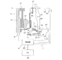
- the clutch device 9 is an example of a device for transmitting power from an engine (not shown) to a transmission (not shown), and is fixed to a flywheel 91 of the engine, for example. .
- the clutch device 9 is a so-called normal open type device. In a state where no operating force is applied to the clutch device 9 from the clutch operating device 1 (described later), power transmission from the engine to the transmission is interrupted. Details of the clutch operating device 1 will be described later.
- the clutch device 9 includes a clutch cover 93, a pressure plate 92, a clutch disk 94, a pressing lever 96, an engagement bearing 97, and a clutch lever 98.
- the clutch cover 93 is fixed to the flywheel 91.
- the pressure plate 92 is supported by the clutch cover 93 so as to be integrally rotatable and movable in the axial direction.
- the pressure plate 92 is coupled to the clutch cover 93 and a plurality of strap plates (not shown) so as to be integrally rotatable.
- the pressure plate 92 is elastically connected to the clutch cover 93 in the axial direction by a strap plate.
- the clutch disc 94 is disposed between the flywheel 91 and the pressure plate 92, and is sandwiched between the flywheel 91 and the pressure plate 92 in the axial direction when the clutch device 9 is connected.
- the clutch disk 94 has a cushioning plate.
- the pressing lever 96 is a substantially annular plate, and is supported by a clutch cover 93 so as to be elastically deformable in the axial direction.
- the elastic force of the pressing lever 96 is small, and the force required for elastic deformation is relatively small.
- the inner peripheral portion of the pressing lever 96 can be pushed in the axial direction by an engagement bearing 97.
- the engagement bearing 97 absorbs the rotational difference between the clutch lever 98 and the pressing lever 96.
- the engagement bearing 97 presses the pressure plate 92 in the axial direction via the pressing lever 96.
- the engagement bearing 97 is driven in the axial direction by the clutch operating device 1 via the clutch lever 98.
- the pressing force acting on the clutch disk 94 via the pressing lever 96 and the pressure plate 92 changes according to the amount of movement of the engagement bearing 97 (the amount of operation of the clutch operating device 1).
- the clutch lever 98 is rotatably supported by a housing (not shown).
- the clutch operating device 1 is a device for operating the clutch device 9 and switches the clutch device 9 to one of a power transmission state and a power cutoff state based on an operation signal output from the transmission ECU 89, for example.
- the power cut-off state means a state where power transmission through the clutch device 9 is completely cut off
- the power transmission state means that power transmission is performed via the clutch device 9. It means that there is.
- the rotational speeds of the flywheel 91 and the input shaft 99 of the transmission are the same.
- the clutch operating device 1 can be applied to various clutch devices having different specifications.
- the clutch operating device 1 will be described by taking the above-described clutch device 9 as an example of an operation target of the clutch operating device 1.
- the clutch operating device 1 includes a drive mechanism 2 (an example of a drive unit), a speed reduction mechanism 3 (an example of a speed reduction unit), and a control unit 8.
- the drive mechanism 2 is a drive source for driving the clutch lever 98 of the clutch device 9 and applies thrust to the clutch lever 98 via the speed reduction mechanism 3.
- the force input from the drive mechanism 2 to the speed reduction mechanism 3 is the driving force F1 (an example of the drive force of the drive unit), and the force output from the speed reduction mechanism 3 is the operation force F2 (an example of the operation force of the clutch device). It is defined as The driving force F1 and the operating force F2 vary according to the force required for the clutch device 9.
- the driving mechanism 2 generates a driving force F1 for driving the clutch device 9.
- the drive mechanism 2 includes a drive motor 23 and a ball screw 22.
- the drive motor 23 is a brushless motor, for example, and has a drive shaft 21 for outputting a rotational drive force.
- the ball screw 22 converts the rotational motion of the drive shaft 21 into linear motion.
- the drive shaft 21 is formed with a male screw, and the ball screw 22 is formed with a female screw.
- a drive shaft 21 is screwed into the ball screw 22.
- the ball screw 22 moves in the axial direction. Thereby, the rotational driving force generated by the drive motor 23 is converted into the axial driving force F1.
- the driving force F ⁇ b> 1 is transmitted to the speed reduction mechanism 3 through the ball screw 22.
- the deceleration mechanism 3 converts the driving force F1 generated by the driving mechanism 2 into an operating force F2. More specifically, the speed reduction mechanism 3 decelerates the drive amount (stroke of the ball screw 22) input from the drive mechanism 2 to amplify the drive force F1 and convert it into the operation force F2 of the clutch device 9.
- the speed reduction mechanism 3 applies the principle of a so-called toggle mechanism, and has a speed reduction ratio characteristic in which the speed reduction ratio gradually increases from the power cutoff state (see FIG. 1) to the power transmission state (see FIG. 2) of the clutch device 9. is doing. Details of the speed reduction mechanism 3 will be described later.
- the control unit 8 includes a control device 83, a first rotation sensor 81, a second rotation sensor 84, and a stroke sensor 82.
- the control device 83 controls the drive motor 23 according to the state of the vehicle. Specifically, control device 83 controls drive motor 23 based on an operation signal output from transmission ECU 89 (FIG. 1).
- the first rotation sensor 81 detects the rotation speed of the flywheel 91.
- the second rotation sensor 84 detects the rotational speed of the input shaft 99 that rotates integrally with the clutch disk 94.
- the stroke sensor 82 detects the stroke S (absolute position) of the clutch lever 98.
- the control device 83 is electrically connected to the first rotation sensor 81, the second rotation sensor 84 and the stroke sensor 82. Detection signals from the first rotation sensor 81, the second rotation sensor 84, and the stroke sensor 82 are input to the control device 83 at a predetermined cycle.
- the control device 83 controls the operation of the drive motor 23 using each detection signal
- the control device 83 controls the drive of the drive motor 23 so that the clutch lever 98 rotates to a predetermined release position. Based on the detection signal of the stroke sensor 82, the control device 83 determines whether or not the clutch lever 98 is in a predetermined position.
- the control device 83 controls the drive of the drive motor 23 so that the clutch lever 98 rotates to the engage position.
- the determination of the engagement position of the clutch lever 98 is performed based on whether or not the rotational speeds of the flywheel 91 and the input shaft 99 are comparable. More specifically, the rotational speeds of the flywheel 91 and the input shaft 99 are determined based on detection signals from the first rotation sensor 81 and the second rotation sensor 84.
- the drive motor 23 drives the clutch lever 98 based on the control signal of the control device 83. Specifically, the drive shaft 21 of the drive motor 23 starts rotating, and the ball screw 22 moves toward pushing the first link member 31. When the first end 31a of the first link member 31 is pushed by the ball screw 22, the first link member 31 rotates about the rotation axis A1. As a result, the driving force of the driving motor 23 is transmitted to the clutch lever 98 via the second link member 32, the coil spring 34 and the third link member 33.
- the drive amount of the drive mechanism 2 (the rotation amount of the drive shaft 21 or the stroke of the ball screw 22) is decelerated by the speed reduction mechanism 3 and converted into a stroke S. Further, the driving force F1 generated by the driving mechanism 2 is amplified by the speed reduction mechanism 3 and converted into the operating force F2.
- the clutch lever 98 is driven by the stroke S by the operating force F2 output from the speed reduction mechanism 3.
- the operating force F2 varies according to the state of the clutch device 9, and the driving force F1 also varies accordingly. That is, the operating force F2 and the driving force F1 vary according to the state of the clutch device 9 and the state of the speed reduction mechanism 3.
- the speed reduction mechanism 3 has a function of automatically adjusting the speed reduction ratio characteristics according to the state of the clutch device 9. In order to realize this function, as shown in FIG. 3 (A) and FIG. 3 (B), the speed reduction mechanism 3 includes a first link member 31, a second link member 32, a third link member 33, Coil spring 34 (an example of an elastic member).
- the first link member 31 is rotatably supported by a housing (not shown) around the rotation axis A1, and is driven to rotate by the drive mechanism 2.
- the first link member 31 is bent in an L shape.
- the first end 31a of the first link member 31 is rotatably connected to the end of the ball screw 22 via a pin.
- the second end 31b of the first link member 31 is rotatably connected to the second link member 32 via a pin.
- the second link member 32 is rotatably connected to the second end portion 31 b of the first link member 31.
- the second link member 32 has a sliding hole 32a.
- a third link member 33 is inserted into the sliding hole 32a.
- the third link member 33 is slidably disposed with the second link member 32 and is connected to the clutch lever 98.
- the third link member 33 includes a rod-shaped shaft portion 33a, a columnar stopper portion 33b, and a connecting portion 33c.
- the shaft portion 33 a is inserted into the sliding hole 32 a of the second link member 32 and is longer than the second link member 32. Since the shaft portion 33a is inserted into the sliding hole 32a, the second link member 32 is movable along the shaft portion 33a.
- the stopper portion 33b is disposed so as to be able to contact the second link member 32, and is formed at the first end portion 33d of the shaft portion 33a.
- the outer diameter of the stopper portion 33b is larger than the outer diameter of the shaft portion 33a and further larger than the inner diameter of the sliding hole 32a.
- the second link member 32 is positioned by the stopper portion 33b.
- the connecting portion 33c is formed at the second end portion 33e of the shaft portion 33a.
- the connecting portion 33c is rotatably connected to the end of the clutch lever 98 via a pin.
- the connecting portion 33c has the same outer dimensions as the stopper portion 33b.
- the coil spring 34 is disposed on a power transmission path from the drive mechanism 2 to the clutch device 9, and is disposed in a compressed state between the second link member 32 and the third link member 33. More specifically, the coil spring 34 is disposed between the second link member 32 and the connecting portion 33c in a pre-compressed state. A shaft portion 33 a is inserted into the coil spring 34. In a state where the second link member 32 is in contact with the stopper portion 33b, the coil spring 34 is compressed between the second link member 32 and the connecting portion 33c. That is, in the initial state shown in FIG. 3A, the second link member 32 is pressed against the stopper portion 33 b of the third link member 33 by the coil spring 34. As shown in FIG. 3B, the coil spring 34 starts to be compressed when a load exceeding the initial compression load Fi is applied. The compression of the coil spring 34 stops at a position where the force F4 acting on the coil spring 34 and the elastic force of the coil spring 34 are balanced.
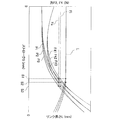
- the first vertical axis shown in FIG. 4 indicates the operating force F2 and the force F4 acting on the coil spring 34
- the second vertical axis indicates the link length L
- the horizontal axis indicates the output side of the speed reduction mechanism 3. Stroke S is shown.
- the link length L is the length shown in FIGS. 3 (A) and 3 (B).
- the change amount of the link length L corresponds to the change amount (compression change amount) of the length of the coil spring 34.
- the relationship between the operating force F2 and the stroke S at the time of product shipment is as shown in the first clutch load characteristic P1.
- the relationship between the operating force F2 and the stroke S when the clutch disk 94 is worn to the maximum allowable wear amount is as shown in the third clutch load characteristic P3.
- An intermediate characteristic between the first clutch load characteristic P1 and the third clutch load characteristic P3 can be represented by a second clutch load characteristic P2. In any case, it can be seen that the required operating force F2 gradually increases as the stroke S increases.
- the curve F41 of the force F4 gradually approaches the curve of the first clutch load characteristic P1.
- the curve F42 of the force F4 gradually approaches the curve of the second clutch load characteristic P2.
- the curve F43 of the force F4 gradually approaches the curve of the third clutch load characteristic P3.
- the curves of the force F4 and the operating force F2 shown in FIG. 4 show the case where the coil spring 34 maintains the initial compression state.
- the force F4 exceeds the initial compression load Fi
- the magnitude of the force F4 Accordingly, the compression of the coil spring 34 proceeds, and the link length L is shortened according to the force F4 as shown in FIG.
- the link length L is reduced. It starts to get shorter.
- the operating force F2 when the compression of the coil spring 34 is started is substantially the same even if the clutch load characteristic changes.
- This operation force F2 is referred to as an operation start operation force Fs in the following description.
- the speed reduction mechanism 3 may be configured such that the operation start operation force Fs changes according to the clutch load characteristics.
- whether or not the coil spring 34 is operated is determined by the force F4 and the initial compression load Fi. Since the force F4 changes according to the operating force F2 and the stroke S, whether or not the coil spring 34 operates and the amount of change in the compression of the coil spring 34 is determined by the relationship between the operating force F2 and the stroke S. The relationship between the operating force F2 and the stroke S means how much operating force F2 is required for a certain stroke S. Therefore, it can be said that whether or not the coil spring 34 operates is determined by the state of the clutch device 9.
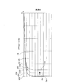
- FIG. 5 shows the reduction ratio characteristics of the reduction mechanism 3.
- the vertical axis of the graph shown in FIG. 5 indicates the reduction ratio of the speed reduction mechanism 3, and the horizontal axis indicates the output side stroke S of the speed reduction mechanism 3.
- the “reduction ratio” here refers to the output drive amount (the stroke of the ball screw 22) input from the drive mechanism 2 (drive unit) to the reduction mechanism 3 (deceleration unit). The value divided by the stroke S).
- the speed reduction mechanism 3 uses the principle of the toggle mechanism, the speed reduction ratio of the speed reduction mechanism 3 increases rapidly at the end of the stroke S.
- the first link member 31 is not directly connected to the third link member 33 with a pin, but is connected to the third link member 33 via the second link member 32 and the coil spring 34. . Therefore, when the compression state of the coil spring 34 changes, the fulcrum position where the first link member 31 and the third link member 33 are connected changes, and the reduction ratio characteristic also changes accordingly. That is, the reduction ratio characteristic of the speed reduction mechanism 3 changes steplessly according to the state of the clutch device 9.
- the third reduction ratio characteristic R3 is the reduction ratio characteristic of the reduction mechanism 3 when the coil spring 34 continues to maintain the initial compression state.
- the first reduction ratio characteristic R1 is a reduction ratio characteristic when the compression amount of the coil spring 34 is maximum.
- the second reduction ratio characteristic R2 is a reduction ratio characteristic of the reduction mechanism 3 when the coil spring 34 is compressed from the initial compression state to a certain extent.
- the compression state of the coil spring 34 is changed by the operating force F2 and the stroke S during the operation of the speed reduction mechanism 3, and during the operation of the speed reduction mechanism 3, the first speed reduction ratio characteristic R1 to the third speed reduction ratio characteristic R3.
- the reduction ratio characteristic changes steplessly within the region of.
- FIG. 6 shows clutch load characteristics and motor torque of the clutch device 9.
- the first vertical axis shown in FIG. 6 indicates the clutch load of the clutch device 9 (more specifically, the operating force F2), and the second vertical axis indicates the motor torque of the drive motor 23.
- the horizontal axis shown in FIG. 6 indicates the stroke S of the clutch operating device 1.
- the clutch load characteristic shown in FIG. 6 changes depending on the state of the clutch device 9.
- the state of the clutch device 9 changes due to individual differences of products and deterioration over time. As deterioration with time, for example, wear of the clutch disk 94 or deterioration of the cushioning plate may be considered.
- the clutch load F0 is the minimum operating force F2 required to maintain the power transmission state of the clutch device 9.
- the stroke S required to obtain the clutch load F0 differs between the first clutch load characteristic P1 to the third clutch load characteristic P3. Specifically, as shown in FIG.
- the first clutch load characteristic P1 requires a stroke S11 to obtain the clutch load F0
- the third clutch load characteristic P3 is longer than the stroke S11 to obtain the clutch load F0. Stroke S31 is required.
- the second clutch load characteristic P2 requires a stroke S21 longer than the stroke S11 in order to obtain the clutch load F0.
- the speed reduction ratio characteristic of the speed reduction mechanism 3 changes.
- the speed reduction ratio characteristic of the speed reduction mechanism 3 changes from the third speed reduction ratio characteristic R3 toward the first speed reduction ratio characteristic R1 in accordance with the compression amount of the coil spring 34. That is, in the case of the first clutch load characteristic P1, the reduction ratio increases early from the stroke S1 corresponding to the operation start operating force Fs.
- the motor torque of the drive motor 23 gradually decreases from the first operating point Q1 corresponding to the stroke S1.
- the force F4 acting on the coil spring 34 reaches the initial compression load Fi.
- the stroke S becomes longer than the stroke S2 the force F4 acting on the coil spring 34 exceeds the initial compression load Fi, and the coil spring 34 starts operating.
- the reduction ratio of the speed reduction mechanism 3 increases early, as in the case of the first clutch load characteristic P1 described above.
- the reference operating force Fs2 and the elastic force of the coil spring 34 are balanced, the compression of the coil spring 34 is stopped, and the change in the reduction ratio characteristic of the speed reduction mechanism 3 is also stopped.
- the motor torque of the drive motor 23 gradually decreases from the second operation point Q2 corresponding to the stroke S2, as indicated by a region T21 in FIG. From FIG. 6, it can be seen that the motor torque can be reduced compared to the motor torque T22 (broken line) when the reduction ratio characteristic is not adjusted.
- the motor torque of the drive motor 23 gradually decreases from the third operating point Q3 corresponding to the stroke S3. From FIG. 6, it can be seen that the motor torque can be reduced compared to the motor torque T32 (broken line) when the reduction ratio characteristic is not adjusted.
- the reduction ratio characteristic of the speed reduction mechanism 3 is automatically adjusted according to the state of the clutch device 9 (more specifically, the relationship between the operating force F2 and the stroke S). Therefore, an increase in motor torque of the drive mechanism 2 due to individual differences in the products of the clutch device 9 can be reduced.
- the reduction ratio characteristic of the reduction mechanism 3 is automatically adjusted according to the amount of wear of the clutch disk 94. Therefore, an increase in load on the drive mechanism 2 due to wear of the clutch disk 94 can also be reduced.
- the clutch device is described by taking the clutch device 9 as an example, but the configuration of the clutch device is not limited to the above-described embodiment.
- the above-described technology can be applied to a normally open type clutch device.
- a twin clutch using two clutch disks may be considered as a clutch device.
- the drive unit has been described by taking the drive mechanism 2 as an example.
- the configuration of the drive unit that generates the driving force is not limited to the drive motor 23 and the ball screw 22.
- another actuator such as a hydraulic cylinder may be employed as the drive unit.
- the speed reduction unit is described by taking the speed reduction mechanism 3 as an example.
- the configuration of the speed reduction unit is not limited to the speed reduction mechanism 3 described above.
- the speed reduction unit may have another configuration.
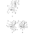
- a modified example of the deceleration unit will be described with reference to FIGS. 7 (A) to 7 (C).
- the speed reduction mechanism 103 of the first modified example applies the principle of a toggle mechanism, and includes a first link member 131, a second link member 32, a third link member 33, and the like. And a coil spring 34.
- the first end 131a of the first link member 131 is rotatably connected to a housing (not shown).
- the second end 131 b of the first link member 131 is rotatably connected to the second link member 32.
- the second link member 32 is pushed downward by the drive mechanism 2.
- the ball screw 22 is connected to the second end 131 b and the second link member 32.
- the drive motor 23 of the drive mechanism 2 is supported by a housing (not shown) so as to be rotatable about the rotation axis A3.
- the coil spring 34 is disposed in a compressed state between the second link member 32 and the third link member 33.
- the connecting portion 33 c of the third link member 33 is connected to the clutch lever 98.
- the speed reduction mechanism 203 of the second modified example applies the principle of a toggle mechanism, and includes a sliding member 231, a second link member 32, a third link member 33, And a coil spring 34.
- the sliding member 231 is movably supported by a guide member 239 fixed to a housing (not shown). Specifically, the sliding member 231 is inserted into the guide groove 239a of the guide member 239. The sliding member 231 is rotatably connected to the second link member 32. The sliding member 231 is pushed downward by the drive mechanism 2.
- the coil spring 34 is disposed in a compressed state between the second link member 32 and the third link member 33.
- the connecting portion 33 c of the third link member 33 is connected to the clutch lever 98.
- the speed reduction mechanism 303 of the third modified example applies the principle of a toggle mechanism, and includes a first link member 331, a second link member 32, and a third link member. 33, a coil spring 34, and an intermediate link member 335.
- the first end 331a of the first link member 331 is rotatably connected to a housing (not shown).
- the second end 331b of the first link member 331 is rotatably connected to the intermediate link member 335.
- the first end 335 a of the intermediate link member 335 is rotatably connected to the first link member 331.
- the first end portion 335 a is pushed downward by the drive mechanism 2.
- a second end 335 b of the intermediate link member 335 is rotatably connected to the second link member 32.
- the second link member 32 and the third link member 33 are movably supported by a guide member 339 fixed to a housing (not shown). Specifically, the second link member 32 and the third link member 33 are inserted into the guide groove 339 a of the guide member 339.
- the connecting portion 33 c of the third link member 33 is connected to the clutch lever 98.
- the drive motor 23 of the drive mechanism 2 is supported by a housing (not shown) so as to be rotatable about the rotation axis A3.
- the elastic member has been described by taking the coil spring 34 as an example, the elastic member used for the speed reduction unit may have another configuration as long as it is a member capable of generating an elastic force.
- the clutch lever 98 may be omitted. In this case, a configuration in which the third link member 33 directly presses the engagement bearing 97 is conceivable.
- another mechanism may be provided between the clutch lever 98 and the speed reduction mechanism 3.
- a slave cylinder and a master cylinder may be provided between the clutch lever 98 and the drive mechanism 2.
Landscapes
- Engineering & Computer Science (AREA)
- General Engineering & Computer Science (AREA)
- Mechanical Engineering (AREA)
- Physics & Mathematics (AREA)
- Electromagnetism (AREA)
- Mechanical Operated Clutches (AREA)
- Hydraulic Clutches, Magnetic Clutches, Fluid Clutches, And Fluid Joints (AREA)
- Power Steering Mechanism (AREA)
Abstract
Description
ノーマルオープンタイプの場合、クラッチ操作装置からクラッチ装置に操作力が付与されていない状態では、クラッチ装置の連結は解除されている。クラッチ装置を連結する際には、レバーを介して駆動機構によりプレッシャプレートが押圧され、プレッシャプレートとフライホイールとの間にクラッチディスクが挟み込まれる。この結果、クラッチディスクを介して変速機の入力シャフトに動力が伝達される。
一方で、クラッチ装置の製品の個体差に起因してクラッチ荷重特性にばらつきが生じる場合があるので、クラッチ荷重と操作力との関係が製品ごとで異なってしまう。したがって、製品の個体差によってクラッチ操作装置の駆動源の負荷もばらつき、その結果、駆動源の負荷が予想以上に増大する場合も考えられる。
しかし、特許文献1に記載の技術では、このような製品の個体差には対応することができない。
本発明の課題は、クラッチ装置の製品の個体差に起因する負荷の増大を低減できるクラッチ操作装置を提供することにある。
また、「減速比」とは、駆動部から減速部に入力される入力駆動量を減速部から出力される出力駆動量で除した値をいう。「減速比特性」とは、出力駆動量と減速比との関係を意味しており、グラフにより1本の線で表すことができる。したがって、「減速比特性を調整する」とは、出力駆動量と減速比との関係を変化させることを意味しており、グラフ上の線の形状を変化させることを意味している。
以上に説明したように、このクラッチ操作装置では、減速部がクラッチ装置の状態に応じて減速比特性を調整可能であるので、製品の個体差に起因してクラッチ装置のクラッチ荷重特性がばらついても、駆動部の負荷の増大を低減することができる。したがって、このクラッチ操作装置であれば、クラッチ装置の製品の個体差に起因する負荷の増大を低減することができる。
図1に示すように、クラッチ装置9は、エンジン(図示せず)からトランスミッション(図示せず)への動力伝達を行うための装置の一例であり、例えばエンジンのフライホイール91に固定されている。クラッチ装置9はいわゆるノーマルオープンタイプの装置である。クラッチ操作装置1(後述)から操作力がクラッチ装置9に付与されていない状態では、エンジンからトランスミッションへの動力伝達が遮断されている。クラッチ操作装置1の詳細については後述する。
クラッチカバー93はフライホイール91に固定されている。プレッシャプレート92はクラッチカバー93により一体回転可能かつ軸方向に移動可能に支持されている。プレッシャプレート92はクラッチカバー93と複数のストラッププレート(図示せず)により一体回転可能に連結されている。また、プレッシャプレート92はストラッププレートによりクラッチカバー93に軸方向に弾性的に連結されている。
クラッチ操作装置1は、クラッチ装置9を操作するための装置であり、例えばトランスミッションECU89から出力される操作信号に基づいて、クラッチ装置9を動力伝達状態および動力遮断状態のうち一方に切り替える。ここで、動力遮断状態とは、クラッチ装置9を介しての動力伝達が完全に遮断されている状態を意味しており、動力伝達状態とは、クラッチ装置9を介して動力伝達が行われている状態を意味している。動力伝達状態では、フライホイール91とトランスミッションの入力シャフト99との回転速度が同じである。
図1および図2に示すように、クラッチ操作装置1は、駆動機構2(駆動部の一例)と、減速機構3(減速部の一例)と、制御ユニット8と、を備えている。
第1回転センサ81はフライホイール91の回転速度を検出する。第2回転センサ84はクラッチディスク94と一体で回転する入力シャフト99の回転速度を検出する。ストロークセンサ82はクラッチレバー98のストロークS(絶対位置)を検出する。制御装置83は第1回転センサ81、第2回転センサ84およびストロークセンサ82と電気的に接続されている。制御装置83には第1回転センサ81、第2回転センサ84およびストロークセンサ82の検出信号が所定の周期で入力される。制御装置83は各検出信号を用いて駆動モータ23の動作を制御する。
ここで、クラッチ操作装置1の動作について簡単に説明する。
図1に示す動力遮断状態では、クラッチ操作装置1で生成される駆動力はエンゲージベアリング97に伝達されていないので、プレッシャプレート92はストラッププレートの弾性力によりクラッチディスク94から離れた位置で保持されている。したがって、フライホイール91の回転がクラッチディスク94には伝達されず、トランスミッションでの変速動作が可能となる。
<減速機構の詳細構成>
減速機構3はクラッチ装置9の状態に応じて減速比特性を自動的に調整する機能を有している。この機能を実現するために、図3(A)および図3(B)に示すように、減速機構3は、第1リンク部材31と、第2リンク部材32と、第3リンク部材33と、コイルスプリング34(弾性部材の一例)と、を有している。
第3リンク部材33は、第2リンク部材32と摺動可能に配置されており、クラッチレバー98に連結されている。具体的には、第3リンク部材33は、棒状の軸部33aと、円柱状のストッパ部33bと、連結部33cと、を有している。軸部33aは、第2リンク部材32の摺動孔32aに挿入されており、第2リンク部材32よりも長い。軸部33aが摺動孔32aに挿入されているので、第2リンク部材32は軸部33aに沿って移動可能となっている。
連結部33cは軸部33aの第2端部33eに形成されている。連結部33cはクラッチレバー98の端部にピンを介して回転可能に連結されている。連結部33cはストッパ部33bと同じくらいの外形寸法を有している。
具体的には図4に示すように、第1クラッチ荷重特性P1の場合、ストロークS1で力F4が初期圧縮荷重Fiに達するので、ストロークS1でコイルスプリング34の圧縮が進行しリンク長さLが短くなりはじめる。第2クラッチ荷重特性P2の場合、ストロークS2で力F4が初期圧縮荷重Fiに達するので、ストロークS2でリンク長さLが短くなりはじめる。さらに、第3クラッチ荷重特性P3の場合、ストロークS3で力F4が初期圧縮荷重Fiに達するので、ストロークS3でリンク長さLが短くなりはじめる。図4に示すように、本実施形態では、コイルスプリング34の圧縮が開始される際の操作力F2は、クラッチ荷重特性が変わっても概ね同じである。この操作力F2を以下の説明では作動開始操作力Fsとする。なお、クラッチ荷重特性に応じて作動開始操作力Fsが変化するように減速機構3が構成されていてもよい。
減速機構3が以上のような構成を有しているので、減速機構3の減速比特性は操作力F2およびストロークSに応じて変化する。ここで、減速機構3の減速比特性についてより詳細に説明する。図5に減速機構3の減速比特性を示す。図5に示すグラフの縦軸は減速機構3の減速比を示しており、横軸は減速機構3の出力側のストロークSを示している。ここでいう「減速比」とは、駆動機構2(駆動部)から減速機構3(減速部)に入力される入力駆動量(ボールネジ22のストローク)を減速機構3から出力される出力駆動量(ストロークS)で除した値をいう。
前述の減速機構3を用いることで、このクラッチ操作装置1ではクラッチ装置9の状態に応じて自動的に減速比特性が調整され、駆動モータ23のモータトルクを低減できる。以下、クラッチ荷重特性およびモータトルクの関係について説明する。
図6にクラッチ装置9のクラッチ荷重特性およびモータトルクを示す。図6に示す第1縦軸はクラッチ装置9のクラッチ荷重(より詳細には、操作力F2)を示しており、第2縦軸は駆動モータ23のモータトルクを示している。また、図6に示す横軸はクラッチ操作装置1のストロークSを示している。
例えば図6に示すように、第1クラッチ荷重特性P1では、クラッチディスク94が摩耗していないので、ストロークSが短くても必要なクラッチ荷重F0を得ることができる。ここで、クラッチ荷重F0とはクラッチ装置9の動力伝達状態を維持するのに最低限必要な操作力F2である。クラッチ荷重F0を得るために必要なストロークSは第1クラッチ荷重特性P1~第3クラッチ荷重特性P3で異なっている。具体的には図6に示すように、第1クラッチ荷重特性P1ではクラッチ荷重F0を得るためにストロークS11が必要となり、第3クラッチ荷重特性P3ではクラッチ荷重F0を得るためにストロークS11よりも長いストロークS31が必要となる。さらに、第2クラッチ荷重特性P2ではクラッチ荷重F0を得るためにストロークS11よりも長いストロークS21が必要となる。
しかし、前述のように、クラッチ装置9の状態に応じて減速機構3の減速比特性が自動的に調整されるので、モータトルクの増大を抑制することができる。具体的には図4および図6に示すように、第1クラッチ荷重特性P1の場合、ストロークSがストロークS1に達すると、コイルスプリング34に作用する力F4が初期圧縮荷重Fiに達し、ストロークSがストロークS1よりも長くなると、コイルスプリング34の圧縮が進行し、減速機構3の減速比が徐々に上昇する。
<クラッチ操作装置の特徴>
このように、このクラッチ操作装置1では、クラッチ装置9の状態(より詳細には、操作力F2およびストロークSの関係)に応じて減速機構3の減速比特性が自動的に調整される。したがって、クラッチ装置9の製品の個体差に起因する駆動機構2のモータトルクの増大を低減することができる。
〔他の実施形態〕
本発明の具体的な構成は、前述の実施形態に限られるものではなく、発明の要旨を逸脱しない範囲で種々の変更および修正が可能である。なお、以降の説明では、前述の実施形態の構成と実質的に同じ機能を有する構成については、同じ符号を使用し、その詳細な説明は省略する。
(B)前述の実施形態では、駆動機構2を例に駆動部を説明しているが、駆動力を生成する駆動部の構成は、駆動モータ23およびボールネジ22に限定されない。例えば、油圧シリンダなどの他のアクチュエータを駆動部として採用してもよい。
図7(A)に示すように、第1変形例の減速機構103は、トグル機構の原理を応用しており、第1リンク部材131と、第2リンク部材32と、第3リンク部材33と、コイルスプリング34と、を有している。第1リンク部材131の第1端部131aはハウジング(図示せず)に回転可能に連結されている。第1リンク部材131の第2端部131bは第2リンク部材32に回転可能に連結されている。第2リンク部材32は駆動機構2により下側に押される。具体的には、ボールネジ22は第2端部131bおよび第2リンク部材32に連結されている。駆動機構2の駆動モータ23は回転軸A3を中心に回転可能にハウジング(図示せず)により支持されている。コイルスプリング34は第2リンク部材32と第3リンク部材33との間に圧縮された状態で配置されている。第3リンク部材33の連結部33cはクラッチレバー98に連結されている。
(D)クラッチレバー98が省略されてもよい。この場合、第3リンク部材33がエンゲージベアリング97を直接押圧する構成が考えられる。逆に、クラッチレバー98と減速機構3との間に他の機構が設けられていてもよい。例えば、クラッチレバー98と駆動機構2との間にスレーブシリンダおよびマスターシリンダが設けられていてもよい。
2 駆動機構(駆動部の一例)
22 ボールネジ
23 駆動モータ
3 減速機構(減速部の一例)
31 第1リンク部材
31a 第1端
31b 第2端部
32 第2リンク部材
32a 摺動孔
33 第3リンク部材
33a 軸部
33b ストッパ部
33c 連結部
33d 第1端部
33e 第2端部
34 コイルスプリング(弾性部材の一例)
9 クラッチ装置
F1 駆動力
F2 操作力
Fs 基準操作力
P1 第1クラッチ荷重特性
P2 第2クラッチ荷重特性
P3 第3クラッチ荷重特性
R1 第1減速比特性
R2 第2減速比特性
R3 第3減速比特性
Claims (9)
- クラッチ装置を操作するためのクラッチ操作装置であって、
駆動力を生成する駆動部と、
前記駆動部から入力される駆動量を減速することで前記駆動力を増幅して前記クラッチ装置の操作力に変換する機構であって、前記クラッチ装置の動力遮断状態から動力伝達状態にかけて徐々に大きくなる減速比特性を有し、前記クラッチ装置の状態に応じて前記減速比特性を調整可能な減速部と、
を備えたクラッチ操作装置。 - 前記減速部は、前記操作力および前記駆動量の関係に応じて前記減速比特性を自動的に調整可能である、
請求項1に記載のクラッチ操作装置。 - 前記減速部は、前記クラッチ装置に作用する前記操作力が基準操作力に達すると前記減速比特性が変化しはじめるように構成されている、
請求項1または2に記載のクラッチ操作装置。 - 前記基準操作力は、前記駆動量に応じて変化する、
請求項3に記載のクラッチ操作装置。 - 前記減速部は、前記駆動部から前記クラッチ装置までの動力伝達経路上に配置され前記基準操作力を決定する弾性部材を有している、
請求項3または4に記載のクラッチ操作装置。 - 前記弾性部材は、予め圧縮された状態で設けられており、初期圧縮荷重を超える荷重が作用すると圧縮を開始し、
前記基準操作力は、前記初期圧縮荷重により決まる、
請求項5に記載のクラッチ操作装置。 - 前記減速部は、前記駆動部により回転駆動される第1リンク部材と、前記第1リンク部材に回転可能に連結された第2リンク部材と、前記第2リンク部材に対して移動可能に配置され前記クラッチ装置に連結された第3リンク部材と、を有しており、
前記弾性部材は、前記第2リンク部材と前記第3リンク部材との間に予め圧縮された状態で配置されている、
請求項5または6に記載のクラッチ操作装置。 - 前記第2リンク部材は、摺動孔を有しており、
前記第3リンク部材は、前記摺動孔に挿入された軸部と、前記軸部の第1端部に形成され前記摺動孔よりも外形が大きいストッパ部と、前記軸部の第2端部に配置され前記クラッチ装置に回転可能に連結された連結部と、を有しており、
前記弾性部材は、前記第2リンク部材と前記連結部との間で予め圧縮されている、請求項7に記載のクラッチ操作装置。 - 前記クラッチ装置が初期状態の場合に、前記減速部は、第1減速比特性を実現し、
前記クラッチ装置が摩耗状態の場合に、前記減速部は、前記第1減速比特性よりも減速比が大きくなる第2減速比特性を実現する、
請求項1から8のいずれかに記載のクラッチ操作装置。
Priority Applications (3)
| Application Number | Priority Date | Filing Date | Title |
|---|---|---|---|
| CN201180029809.1A CN102959265B (zh) | 2010-07-07 | 2011-06-14 | 离合器操纵装置 |
| DE112011102280T DE112011102280T5 (de) | 2010-07-07 | 2011-06-14 | Kupplungsbetätigungsvorrichtung |
| US13/807,514 US8960400B2 (en) | 2010-07-07 | 2011-06-14 | Clutch operating device |
Applications Claiming Priority (2)
| Application Number | Priority Date | Filing Date | Title |
|---|---|---|---|
| JP2010155075A JP4962997B2 (ja) | 2010-07-07 | 2010-07-07 | クラッチ操作装置 |
| JP2010-155075 | 2010-07-07 |
Publications (1)
| Publication Number | Publication Date |
|---|---|
| WO2012005091A1 true WO2012005091A1 (ja) | 2012-01-12 |
Family
ID=45441077
Family Applications (1)
| Application Number | Title | Priority Date | Filing Date |
|---|---|---|---|
| PCT/JP2011/063599 Ceased WO2012005091A1 (ja) | 2010-07-07 | 2011-06-14 | クラッチ操作装置 |
Country Status (5)
| Country | Link |
|---|---|
| US (1) | US8960400B2 (ja) |
| JP (1) | JP4962997B2 (ja) |
| CN (1) | CN102959265B (ja) |
| DE (1) | DE112011102280T5 (ja) |
| WO (1) | WO2012005091A1 (ja) |
Families Citing this family (10)
| Publication number | Priority date | Publication date | Assignee | Title |
|---|---|---|---|---|
| KR101822204B1 (ko) * | 2012-12-17 | 2018-01-26 | 현대자동차주식회사 | 차량용 클러치 액추에이터 |
| CN103967970A (zh) * | 2014-05-16 | 2014-08-06 | 西华大学 | 一种离合器的操纵机构及其控制方法 |
| DE102016201886B4 (de) | 2016-02-09 | 2024-08-29 | Schaeffler Technologies AG & Co. KG | Betätigungsvorrichtung mit einem Sensor zur Detektierung eines Signalgebers an einem Kupplungssystem und Kupplungssystem mit Betätigungsvorrichtung |
| KR101862471B1 (ko) * | 2016-10-21 | 2018-05-29 | 현대다이모스(주) | 듀얼클러치 액츄에이터 |
| US11105412B2 (en) | 2016-12-22 | 2021-08-31 | Eaton Cummins Automated Transmission Technologies Llc | System, method, and apparatus for managing transmission shutdown operations |
| WO2018118131A1 (en) | 2016-12-22 | 2018-06-28 | Eaton Corporation | System, method, and apparatus for operating a high efficiency, high output transmission |
| US10584778B2 (en) | 2016-12-22 | 2020-03-10 | Eaton Cummins Automated Transmission Technologies, Llc | High efficiency, high output transmission |
| CN108571541A (zh) * | 2017-03-10 | 2018-09-25 | 上海汽车集团股份有限公司 | 汽车及其离合器静液分离系统 |
| KR101953030B1 (ko) * | 2017-06-23 | 2019-02-27 | 현대트랜시스 주식회사 | 차량용 클러치 액추에이터 |
| KR101953029B1 (ko) * | 2017-06-23 | 2019-02-27 | 현대트랜시스 주식회사 | 클러치 액츄에이터 |
Citations (8)
| Publication number | Priority date | Publication date | Assignee | Title |
|---|---|---|---|---|
| JPS61130628A (ja) * | 1984-11-30 | 1986-06-18 | Hino Motors Ltd | クラツチ・レバ−位置調整機構 |
| JPH0861392A (ja) * | 1994-08-22 | 1996-03-08 | Toyota Motor Corp | 無調整式クラッチにおける摩耗検出機構 |
| JP2004116689A (ja) * | 2002-09-27 | 2004-04-15 | Daihatsu Motor Co Ltd | 発進クラッチのクリープ力制御方法 |
| JP2006071070A (ja) * | 2004-09-06 | 2006-03-16 | Gkn ドライブライン トルクテクノロジー株式会社 | カップリング装置 |
| JP2008043992A (ja) * | 2006-08-21 | 2008-02-28 | Murata Mach Ltd | リニアモータ搭載プレス機械 |
| JP2009264512A (ja) * | 2008-04-25 | 2009-11-12 | Aisin Ai Co Ltd | クラッチ操作装置 |
| JP2011052790A (ja) * | 2009-09-03 | 2011-03-17 | Exedy Corp | クラッチ操作装置 |
| JP2011052789A (ja) * | 2009-09-03 | 2011-03-17 | Exedy Corp | クラッチ操作装置 |
Family Cites Families (6)
| Publication number | Priority date | Publication date | Assignee | Title |
|---|---|---|---|---|
| DE2313885A1 (de) | 1973-03-20 | 1974-10-03 | Guenther Niessen | Computer. nachbau der teile des gehirns, die fuer das denken verantwortlich sind |
| GB2313885B (en) | 1996-06-05 | 2001-02-14 | Luk Getriebe Systeme Gmbh | Operating device |
| WO2002101258A2 (de) * | 2001-06-13 | 2002-12-19 | Luk Lamellen Und Kupplungsbau Beteiligungs Kg | Kupplungsbetätigungsvorrichtung sowie verfahren zum ermitteln von kupplugsparametern |
| AT5722U1 (de) * | 2001-09-18 | 2002-10-25 | Steyr Powertrain Ag & Co Kg | Vorrichtung und verfahren zur einstellung des von einer reibungskupplung übertragenen drehmomentes |
| DE102007021302B4 (de) * | 2007-05-07 | 2015-09-10 | Magna Powertrain Ag & Co. Kg | Verfahren und Vorrichtung zum Einstellen des von einer Reibungskupplung übertragenen Drehmoments |
| CN201363377Y (zh) * | 2009-01-23 | 2009-12-16 | 浙江钱江摩托股份有限公司 | 一种离合器操纵机构 |
-
2010
- 2010-07-07 JP JP2010155075A patent/JP4962997B2/ja not_active Expired - Fee Related
-
2011
- 2011-06-14 CN CN201180029809.1A patent/CN102959265B/zh not_active Expired - Fee Related
- 2011-06-14 WO PCT/JP2011/063599 patent/WO2012005091A1/ja not_active Ceased
- 2011-06-14 US US13/807,514 patent/US8960400B2/en not_active Expired - Fee Related
- 2011-06-14 DE DE112011102280T patent/DE112011102280T5/de not_active Withdrawn
Patent Citations (8)
| Publication number | Priority date | Publication date | Assignee | Title |
|---|---|---|---|---|
| JPS61130628A (ja) * | 1984-11-30 | 1986-06-18 | Hino Motors Ltd | クラツチ・レバ−位置調整機構 |
| JPH0861392A (ja) * | 1994-08-22 | 1996-03-08 | Toyota Motor Corp | 無調整式クラッチにおける摩耗検出機構 |
| JP2004116689A (ja) * | 2002-09-27 | 2004-04-15 | Daihatsu Motor Co Ltd | 発進クラッチのクリープ力制御方法 |
| JP2006071070A (ja) * | 2004-09-06 | 2006-03-16 | Gkn ドライブライン トルクテクノロジー株式会社 | カップリング装置 |
| JP2008043992A (ja) * | 2006-08-21 | 2008-02-28 | Murata Mach Ltd | リニアモータ搭載プレス機械 |
| JP2009264512A (ja) * | 2008-04-25 | 2009-11-12 | Aisin Ai Co Ltd | クラッチ操作装置 |
| JP2011052790A (ja) * | 2009-09-03 | 2011-03-17 | Exedy Corp | クラッチ操作装置 |
| JP2011052789A (ja) * | 2009-09-03 | 2011-03-17 | Exedy Corp | クラッチ操作装置 |
Also Published As
| Publication number | Publication date |
|---|---|
| JP2012017795A (ja) | 2012-01-26 |
| DE112011102280T5 (de) | 2013-05-29 |
| CN102959265A (zh) | 2013-03-06 |
| US8960400B2 (en) | 2015-02-24 |
| CN102959265B (zh) | 2015-06-17 |
| US20130112525A1 (en) | 2013-05-09 |
| JP4962997B2 (ja) | 2012-06-27 |
Similar Documents
| Publication | Publication Date | Title |
|---|---|---|
| JP4962997B2 (ja) | クラッチ操作装置 | |
| RU2561431C2 (ru) | Двойное сцепление с дифференциатором | |
| KR101417665B1 (ko) | 클러치 액츄에이터의 마모보상장치 | |
| US10663015B2 (en) | Clutch actuator with automatic wear compensation | |
| CN103348156B (zh) | 离合器操纵装置 | |
| JP4921576B2 (ja) | クラッチ操作装置 | |
| WO2011027687A1 (ja) | クラッチ操作装置 | |
| US10844912B2 (en) | Reduced vibration clutch actuator | |
| WO2015119077A1 (ja) | 運動変換装置およびクラッチアクチュエータ | |
| IN2014DN10179A (ja) | ||
| US20190360536A1 (en) | Clutch engaging/releasing device | |
| JP4975723B2 (ja) | モータサイクル用クラッチ装置 | |
| KR101526789B1 (ko) | 클러치 액추에이터 | |
| CN104822958B (zh) | 分离系统 | |
| WO2011027693A1 (ja) | クラッチ操作装置 | |
| JP5600556B2 (ja) | クラッチ作動装置 | |
| JP2007533926A (ja) | クラッチ | |
| JP2009537768A (ja) | クラッチ調節装置及びその制御方法 | |
| JP2015068456A (ja) | 制動装置 | |
| JP2009174618A (ja) | クラッチ装置 | |
| JP2013047545A (ja) | ディスクブレーキ | |
| JP6318754B2 (ja) | ダンパ装置 | |
| CN111207162A (zh) | 具有自动分离系统的离合器操作系统的预加载荷调节方法 | |
| BG110909A (bg) | Устройство за намаляване на фрикционни самовъзбуждащи се трептения, възникващи в системи с триещи съединители |
Legal Events
| Date | Code | Title | Description |
|---|---|---|---|
| WWE | Wipo information: entry into national phase |
Ref document number: 201180029809.1 Country of ref document: CN |
|
| 121 | Ep: the epo has been informed by wipo that ep was designated in this application |
Ref document number: 11803427 Country of ref document: EP Kind code of ref document: A1 |
|
| WWE | Wipo information: entry into national phase |
Ref document number: 13807514 Country of ref document: US |
|
| WWE | Wipo information: entry into national phase |
Ref document number: 112011102280 Country of ref document: DE Ref document number: 1120111022808 Country of ref document: DE |
|
| 122 | Ep: pct application non-entry in european phase |
Ref document number: 11803427 Country of ref document: EP Kind code of ref document: A1 |