WO2012004644A1 - Système de gestion d'énergie - Google Patents
Système de gestion d'énergie Download PDFInfo
- Publication number
- WO2012004644A1 WO2012004644A1 PCT/IB2011/001396 IB2011001396W WO2012004644A1 WO 2012004644 A1 WO2012004644 A1 WO 2012004644A1 IB 2011001396 W IB2011001396 W IB 2011001396W WO 2012004644 A1 WO2012004644 A1 WO 2012004644A1
- Authority
- WO
- WIPO (PCT)
- Prior art keywords
- energy
- hot water
- ice
- storage battery
- heat pump
- Prior art date
Links
Images


Classifications
-
- F—MECHANICAL ENGINEERING; LIGHTING; HEATING; WEAPONS; BLASTING
- F24—HEATING; RANGES; VENTILATING
- F24F—AIR-CONDITIONING; AIR-HUMIDIFICATION; VENTILATION; USE OF AIR CURRENTS FOR SCREENING
- F24F5/00—Air-conditioning systems or apparatus not covered by F24F1/00 or F24F3/00, e.g. using solar heat or combined with household units such as an oven or water heater
- F24F5/0046—Air-conditioning systems or apparatus not covered by F24F1/00 or F24F3/00, e.g. using solar heat or combined with household units such as an oven or water heater using natural energy, e.g. solar energy, energy from the ground
-
- F—MECHANICAL ENGINEERING; LIGHTING; HEATING; WEAPONS; BLASTING
- F24—HEATING; RANGES; VENTILATING
- F24F—AIR-CONDITIONING; AIR-HUMIDIFICATION; VENTILATION; USE OF AIR CURRENTS FOR SCREENING
- F24F5/00—Air-conditioning systems or apparatus not covered by F24F1/00 or F24F3/00, e.g. using solar heat or combined with household units such as an oven or water heater
- F24F5/0007—Air-conditioning systems or apparatus not covered by F24F1/00 or F24F3/00, e.g. using solar heat or combined with household units such as an oven or water heater cooling apparatus specially adapted for use in air-conditioning
- F24F5/0017—Air-conditioning systems or apparatus not covered by F24F1/00 or F24F3/00, e.g. using solar heat or combined with household units such as an oven or water heater cooling apparatus specially adapted for use in air-conditioning using cold storage bodies, e.g. ice
-
- F—MECHANICAL ENGINEERING; LIGHTING; HEATING; WEAPONS; BLASTING
- F25—REFRIGERATION OR COOLING; COMBINED HEATING AND REFRIGERATION SYSTEMS; HEAT PUMP SYSTEMS; MANUFACTURE OR STORAGE OF ICE; LIQUEFACTION SOLIDIFICATION OF GASES
- F25B—REFRIGERATION MACHINES, PLANTS OR SYSTEMS; COMBINED HEATING AND REFRIGERATION SYSTEMS; HEAT PUMP SYSTEMS
- F25B27/00—Machines, plants or systems, using particular sources of energy
- F25B27/002—Machines, plants or systems, using particular sources of energy using solar energy
-
- H—ELECTRICITY
- H01—ELECTRIC ELEMENTS
- H01M—PROCESSES OR MEANS, e.g. BATTERIES, FOR THE DIRECT CONVERSION OF CHEMICAL ENERGY INTO ELECTRICAL ENERGY
- H01M10/00—Secondary cells; Manufacture thereof
- H01M10/42—Methods or arrangements for servicing or maintenance of secondary cells or secondary half-cells
- H01M10/46—Accumulators structurally combined with charging apparatus
- H01M10/465—Accumulators structurally combined with charging apparatus with solar battery as charging system
-
- H—ELECTRICITY
- H02—GENERATION; CONVERSION OR DISTRIBUTION OF ELECTRIC POWER
- H02J—CIRCUIT ARRANGEMENTS OR SYSTEMS FOR SUPPLYING OR DISTRIBUTING ELECTRIC POWER; SYSTEMS FOR STORING ELECTRIC ENERGY
- H02J7/00—Circuit arrangements for charging or depolarising batteries or for supplying loads from batteries
- H02J7/34—Parallel operation in networks using both storage and other dc sources, e.g. providing buffering
- H02J7/35—Parallel operation in networks using both storage and other dc sources, e.g. providing buffering with light sensitive cells
-
- F—MECHANICAL ENGINEERING; LIGHTING; HEATING; WEAPONS; BLASTING
- F24—HEATING; RANGES; VENTILATING
- F24F—AIR-CONDITIONING; AIR-HUMIDIFICATION; VENTILATION; USE OF AIR CURRENTS FOR SCREENING
- F24F5/00—Air-conditioning systems or apparatus not covered by F24F1/00 or F24F3/00, e.g. using solar heat or combined with household units such as an oven or water heater
- F24F5/0046—Air-conditioning systems or apparatus not covered by F24F1/00 or F24F3/00, e.g. using solar heat or combined with household units such as an oven or water heater using natural energy, e.g. solar energy, energy from the ground
- F24F2005/0064—Air-conditioning systems or apparatus not covered by F24F1/00 or F24F3/00, e.g. using solar heat or combined with household units such as an oven or water heater using natural energy, e.g. solar energy, energy from the ground using solar energy
-
- F—MECHANICAL ENGINEERING; LIGHTING; HEATING; WEAPONS; BLASTING
- F25—REFRIGERATION OR COOLING; COMBINED HEATING AND REFRIGERATION SYSTEMS; HEAT PUMP SYSTEMS; MANUFACTURE OR STORAGE OF ICE; LIQUEFACTION SOLIDIFICATION OF GASES
- F25B—REFRIGERATION MACHINES, PLANTS OR SYSTEMS; COMBINED HEATING AND REFRIGERATION SYSTEMS; HEAT PUMP SYSTEMS
- F25B2400/00—General features or devices for refrigeration machines, plants or systems, combined heating and refrigeration systems or heat-pump systems, i.e. not limited to a particular subgroup of F25B
- F25B2400/24—Storage receiver heat
-
- Y—GENERAL TAGGING OF NEW TECHNOLOGICAL DEVELOPMENTS; GENERAL TAGGING OF CROSS-SECTIONAL TECHNOLOGIES SPANNING OVER SEVERAL SECTIONS OF THE IPC; TECHNICAL SUBJECTS COVERED BY FORMER USPC CROSS-REFERENCE ART COLLECTIONS [XRACs] AND DIGESTS
- Y02—TECHNOLOGIES OR APPLICATIONS FOR MITIGATION OR ADAPTATION AGAINST CLIMATE CHANGE
- Y02A—TECHNOLOGIES FOR ADAPTATION TO CLIMATE CHANGE
- Y02A30/00—Adapting or protecting infrastructure or their operation
- Y02A30/27—Relating to heating, ventilation or air conditioning [HVAC] technologies
- Y02A30/272—Solar heating or cooling
-
- Y—GENERAL TAGGING OF NEW TECHNOLOGICAL DEVELOPMENTS; GENERAL TAGGING OF CROSS-SECTIONAL TECHNOLOGIES SPANNING OVER SEVERAL SECTIONS OF THE IPC; TECHNICAL SUBJECTS COVERED BY FORMER USPC CROSS-REFERENCE ART COLLECTIONS [XRACs] AND DIGESTS
- Y02—TECHNOLOGIES OR APPLICATIONS FOR MITIGATION OR ADAPTATION AGAINST CLIMATE CHANGE
- Y02B—CLIMATE CHANGE MITIGATION TECHNOLOGIES RELATED TO BUILDINGS, e.g. HOUSING, HOUSE APPLIANCES OR RELATED END-USER APPLICATIONS
- Y02B10/00—Integration of renewable energy sources in buildings
- Y02B10/10—Photovoltaic [PV]
-
- Y—GENERAL TAGGING OF NEW TECHNOLOGICAL DEVELOPMENTS; GENERAL TAGGING OF CROSS-SECTIONAL TECHNOLOGIES SPANNING OVER SEVERAL SECTIONS OF THE IPC; TECHNICAL SUBJECTS COVERED BY FORMER USPC CROSS-REFERENCE ART COLLECTIONS [XRACs] AND DIGESTS
- Y02—TECHNOLOGIES OR APPLICATIONS FOR MITIGATION OR ADAPTATION AGAINST CLIMATE CHANGE
- Y02B—CLIMATE CHANGE MITIGATION TECHNOLOGIES RELATED TO BUILDINGS, e.g. HOUSING, HOUSE APPLIANCES OR RELATED END-USER APPLICATIONS
- Y02B10/00—Integration of renewable energy sources in buildings
- Y02B10/20—Solar thermal
-
- Y—GENERAL TAGGING OF NEW TECHNOLOGICAL DEVELOPMENTS; GENERAL TAGGING OF CROSS-SECTIONAL TECHNOLOGIES SPANNING OVER SEVERAL SECTIONS OF THE IPC; TECHNICAL SUBJECTS COVERED BY FORMER USPC CROSS-REFERENCE ART COLLECTIONS [XRACs] AND DIGESTS
- Y02—TECHNOLOGIES OR APPLICATIONS FOR MITIGATION OR ADAPTATION AGAINST CLIMATE CHANGE
- Y02E—REDUCTION OF GREENHOUSE GAS [GHG] EMISSIONS, RELATED TO ENERGY GENERATION, TRANSMISSION OR DISTRIBUTION
- Y02E10/00—Energy generation through renewable energy sources
- Y02E10/50—Photovoltaic [PV] energy
- Y02E10/56—Power conversion systems, e.g. maximum power point trackers
-
- Y—GENERAL TAGGING OF NEW TECHNOLOGICAL DEVELOPMENTS; GENERAL TAGGING OF CROSS-SECTIONAL TECHNOLOGIES SPANNING OVER SEVERAL SECTIONS OF THE IPC; TECHNICAL SUBJECTS COVERED BY FORMER USPC CROSS-REFERENCE ART COLLECTIONS [XRACs] AND DIGESTS
- Y02—TECHNOLOGIES OR APPLICATIONS FOR MITIGATION OR ADAPTATION AGAINST CLIMATE CHANGE
- Y02E—REDUCTION OF GREENHOUSE GAS [GHG] EMISSIONS, RELATED TO ENERGY GENERATION, TRANSMISSION OR DISTRIBUTION
- Y02E60/00—Enabling technologies; Technologies with a potential or indirect contribution to GHG emissions mitigation
- Y02E60/10—Energy storage using batteries
-
- Y—GENERAL TAGGING OF NEW TECHNOLOGICAL DEVELOPMENTS; GENERAL TAGGING OF CROSS-SECTIONAL TECHNOLOGIES SPANNING OVER SEVERAL SECTIONS OF THE IPC; TECHNICAL SUBJECTS COVERED BY FORMER USPC CROSS-REFERENCE ART COLLECTIONS [XRACs] AND DIGESTS
- Y02—TECHNOLOGIES OR APPLICATIONS FOR MITIGATION OR ADAPTATION AGAINST CLIMATE CHANGE
- Y02E—REDUCTION OF GREENHOUSE GAS [GHG] EMISSIONS, RELATED TO ENERGY GENERATION, TRANSMISSION OR DISTRIBUTION
- Y02E60/00—Enabling technologies; Technologies with a potential or indirect contribution to GHG emissions mitigation
- Y02E60/14—Thermal energy storage
-
- Y—GENERAL TAGGING OF NEW TECHNOLOGICAL DEVELOPMENTS; GENERAL TAGGING OF CROSS-SECTIONAL TECHNOLOGIES SPANNING OVER SEVERAL SECTIONS OF THE IPC; TECHNICAL SUBJECTS COVERED BY FORMER USPC CROSS-REFERENCE ART COLLECTIONS [XRACs] AND DIGESTS
- Y02—TECHNOLOGIES OR APPLICATIONS FOR MITIGATION OR ADAPTATION AGAINST CLIMATE CHANGE
- Y02E—REDUCTION OF GREENHOUSE GAS [GHG] EMISSIONS, RELATED TO ENERGY GENERATION, TRANSMISSION OR DISTRIBUTION
- Y02E70/00—Other energy conversion or management systems reducing GHG emissions
- Y02E70/30—Systems combining energy storage with energy generation of non-fossil origin
Definitions
- the present invention relates to an energy management system for managing energy consumed in a house or office.
- Patent Document 1 discloses a heat pump hot water supply system that reduces electricity charges by operating a heat pump water heater in the midnight hours when electricity charges are low and storing hot water used the next day in a hot water storage tank.
- JP-A-9-68369 see paragraph 0016)
- An energy management system includes a solar cell, a grid-connected photovoltaic power generation system having a power conditioner that converts electric energy generated by the solar cell into predetermined electric energy, a storage battery, A storage battery system having a charge / discharge device for storing electrical energy in the storage battery and discharging the stored electrical energy; a heat pump water heater for generating hot water by consuming electrical energy; and a heat pump hot water supply system having a hot water storage tank; An ice making device that consumes electric energy to generate ice and an ice heat storage air conditioning system having a heat storage tank for storing the generated ice, and the electric energy generated by the solar power generation system is stored in the storage battery Excess electric energy that cannot be charged to the storage battery is generated by the heat pump hot water supply system.
- the power conditioner is transmitted with information on surplus electrical energy from the charging / discharging device, and based on the information, from the solar power generation system or the storage battery system to the heat pump hot water supply system or the It is preferable that surplus electrical energy is supplied to the ice thermal storage air conditioning system.
- a temperature sensor for detecting an outside air temperature is further provided. Based on the detection result of the temperature sensor and information on excess heat energy from the heat pump water heater and the ice making device, the heat pump hot water system or It is preferable that surplus thermal energy is supplied to the photovoltaic power generation system or the storage battery system from the ice storage type air conditioning system.
- information on surplus electrical energy is transmitted from the power conditioner and the charging / discharging device, and based on the information, the heat pump hot water supply system or the ice from the solar power generation system or the storage battery system. It is preferable to include a control device that supplies excess electrical energy to the heat storage type air conditioning system.
- information on excess heat energy is transmitted from the heat pump water heater and the ice making device, and based on the information, from the heat pump hot water system or the ice regenerative air conditioning system to the solar power generation system or It is preferable to provide a control device that supplies surplus thermal energy to the storage battery system. According to the present invention, it is possible to efficiently generate and use electric energy and heat energy to save energy.
- 1A is a block diagram of an energy management system according to Embodiment 1 of the present invention
- 1B is a block diagram
- 2A is a block diagram of an energy management system according to Embodiment 2 of the present invention
- 2B is a block diagram.
- the energy management system according to the present invention is not limited to a detached house, and can be installed in an apartment house, a commercial facility, an office building, or the like.
- the energy management system of the present embodiment includes a photovoltaic power generation system 1, a storage battery system 2, a heat pump hot water supply system 3, an ice thermal storage air conditioning system 4, and a watt hour meter 6. Yes.
- the solar power generation system is a grid-connected type connected to a commercial AC power system 7 via a watt-hour meter 6, and includes a solar cell array 10 that converts solar energy into electric energy, and a solar cell array. And a power conditioner 11 that converts electrical energy generated (converted) at 10 into predetermined electrical energy suitable for a load (such as an electrical device in a house).
- the power conditioner 11 includes various loads (a heat pump hot water supply system 3 and an ice regenerative air conditioning system 4) in a house through electric power supplied from the solar cell array 10 or the AC power system 7 via a power supply line L2. The same shall apply hereinafter).
- the power conditioner 11 can reversely flow (sell power) the surplus electrical energy to the AC power system 7 via the power line L1, as will be described later.
- the storage battery system 2 charges the storage battery 20 with the storage battery 20 such as a lithium ion battery and the electric energy supplied from the power conditioner 11 via the power supply line L3, and discharges the electric energy stored in the storage battery 20.
- a charge / discharge device 21 that supplies the load via the power conditioner 11.
- the heat pump hot water supply system 3 includes a heat pump water heater 30 that generates hot water by consuming electric energy supplied via the power supply line L2, and a hot water storage tank 31 that stores hot water generated by the heat pump water heater 30. Yes.
- a hot water pipe P1 is connected to the hot water tank 31, and hot water (thermal energy) stored in the hot water tank 31 is circulated to the hot water pipe P1 by a circulation pump (not shown).
- a heat exchanger (not shown) is installed in the vicinity of the solar cell array 10 and the storage battery 20, and the heat energy of hot water (warm water) circulating through the hot water pipe P1 is supplied via the heat exchanger.
- the battery array 10 and the storage battery 20 are kept warm.
- the ice heat storage air conditioning system 4 is stored in the ice making device 40 that consumes electric energy supplied via the power supply line L2 to generate ice, the heat storage tank 41 that stores the generated ice, and the heat storage tank 41.
- a radiator 42 for radiating ice (heat energy) to cool the room.
- the heat storage tank 41 is connected with a cold air pipe P2, and heat energy (cold air) stored in the heat storage tank 41 by a circulation pump (not shown) is circulated to the cold air pipe P2. Then, a radiator (not shown) is installed in the vicinity of the solar cell array 10 and the storage battery 20, and the thermal energy of the cold air circulating through the cold air pipe P2 is supplied via the radiator, so that the solar cell array 10 and the storage battery. 20 is cooled.
- the watt-hour meter 6 individually determines the amount of power flowing from the AC power system 7 to the power conditioner 11 (the amount of purchased power) and the amount of power flowing back from the power conditioner 11 to the AC power system 7 (the amount of power sold). Has the function to measure.
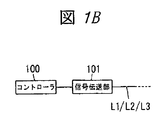
- the power conditioner 11, the charging / discharging device 21, the heat pump water heater 30, the ice making device 40, and the watt-hour meter 6 each include a controller 100 and a signal transmission unit 101 (see FIG. 1B).
- the signal transmission unit 101 performs data transmission using the power line L1 or the power supply lines L2 and L3 as a transmission path.
- the signal transmission unit 101 has a high frequency to an AC voltage or a DC voltage supplied via the power line L1 or the power supply lines L2 and L3. The signal voltage is superimposed.
- the technology for sharing the power feeding line and the data transmission transmission line is well known in the art, such as power line carrier communication, detailed description thereof will be omitted.
- the controller 100 includes a processor such as a CPU, and performs a process described later by executing a dedicated program on the processor. Each controller 100 is assigned a unique identification code, and the identification code becomes an address of each controller 100 in data transmission. Next, the operation of this embodiment will be described. First, the use of electric energy will be described.
- the power conditioner 11 stores the electric energy generated by the solar cell array 10 in the storage battery 20 by sending it to the charging / discharging device 21.
- the controller 100 of the charging / discharging device 21 constantly monitors the amount of electricity stored in the storage battery 20, and when the storage battery 20 is fully charged, a command to stop charging is sent from the signal transmission unit 101 to the controller 100 of the power conditioner 11 via the feeder line L3. Transmit to.
- the controller 100 of the power conditioner 11 supplies electric energy via the power supply line L3 until a charge stop command is received from the controller 100 of the charge / discharge device 21, and stops supplying the charge stop command when the charge stop command is received. To do. Furthermore, when there is surplus electrical energy that cannot be charged in the corresponding storage battery, the controller 100 of the power conditioner 11 sends a command for inquiring whether reverse power flow (power sale) to the AC power system 7 is possible from the signal transmission unit 101 through the power line L1. To the watt hour meter 6.
- the controller 100 of the watt hour meter 6 When the controller 100 of the watt hour meter 6 receives the command, it determines whether or not reverse power flow (power sale) is possible based on the current state of the AC power system 7, and the determination result is sent from the signal transmission unit 101 to the power line L 1. To the controller 100 of the power conditioner 11. When the system voltage of the AC power system 7 exceeds a predetermined voltage, or when the daily power sales amount (integrated power amount) exceeds a predetermined upper limit value, the watt-hour meter 6 is a reverse power flow. Judged as impossible, otherwise judged as reverse flow possible.
- the controller 100 of the power conditioner 11 transfers the electric energy generated by the solar cell array 10 to the AC power system 7 via the power line L1. Reverse current.
- the controller 100 of the power conditioner 11 is at least one of the controller 100 of the heat pump water heater 30 and the controller 100 of the ice making device 40.
- a command for instructing the start of operation is transmitted from the signal transmission unit 101 via the feeder line L2.
- the controller 100 of the heat pump water heater 30 or the controller 100 of the ice making device 40 receives an operation start command from the controller 100 of the power conditioner 11, the controller 100 starts the operation and consumes electric energy supplied via the power supply line L2. Hot water or ice is generated and stored in the hot water storage tank 31 or the heat storage tank 41.
- thermal energy can be interchanged between the systems. For example, since the performance of the solar cell array 10 and the storage battery 20 may decrease when the temperature decreases, if the solar cell array 10 and the storage battery 20 are warmed using the thermal energy stored in the hot water storage tank 31, the temperature is low. The performance degradation at the time of temperature can be suppressed.
- a temperature sensor 8 that detects the outside air temperature is connected to the controller 100 of the power conditioner 11 and the controller 100 of the charge / discharge device 21.
- the outside air temperature detected by the temperature sensor reaches a high temperature range (for example, 30 degrees Celsius or higher) or the maximum daily temperature, the ice making device 40 is controlled by the controller 100 of the power conditioner 11 and the controller 100 of the charge / discharge device 21.
- a cooling request command is transmitted from the signal transmission unit 101 to the controller 100.
- the controller 100 of the ice making device 40 that has received the command operates the circulation pump if the amount of heat stored in the heat storage tank 41 (the amount of ice) is full or has its own ice making capacity, and operates the heat storage tank 41.
- the cold air is circulated through the cold air pipe P2.
- the thermal energy of the cold air which circulates through the cold air piping P2 is supplied to the solar cell array 10 and the storage battery 20 through the radiator and cooled.
- the controller 100 of the power conditioner 11 and the controller 100 of the charging / discharging device 21 are used.
- the controller 100 transmits a heat insulation request command from the signal transmission unit 101.
- the controller 100 of the heat pump water heater 30 that has received the command operates the circulation pump and passes the hot water pipe 31 through the hot water pipe P1 if the hot water capacity of the hot water tank 31 is full or if its own hot water capacity is sufficient. Circulate hot water (heat energy). And the thermal energy of the hot water (warm water) circulating through the hot water pipe P1 is supplied to the solar cell array 10 and the storage battery 20 through the heat exchanger to be kept warm. As described above, in the energy management system according to the present embodiment, the surplus electrical energy generated by the photovoltaic power generation system 1 is reversely flowed, thereby saving energy and reducing the electricity bill.
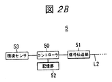
- the energy management system of the present embodiment includes a photovoltaic power generation system 1, a storage battery system 2, a heat pump hot water supply system 3, an ice thermal storage air conditioning system 4, a control device 5, and a watt hour meter 6. It consists of and. However, since the configuration other than the control device 5 is the same as that of the first embodiment, the same components are denoted by the same reference numerals and the description thereof is omitted. As shown in FIG. 2B, the control device 5 includes a controller 50, a signal transmission unit 51, a storage unit 52, and an environmental sensor 53. The signal transmission unit 51 performs data transmission using the power line L1 and the power supply lines L2 and L3 as transmission lines.
- the signal transmission unit 51 has a high frequency to an AC voltage or a DC voltage supplied via the power line L1 and the power supply lines L2 and L3.
- the signal voltage is superimposed.
- the environmental sensor 53 detects the outside air temperature, the outside air humidity, the amount of solar radiation, etc. periodically (for example, every several minutes to several tens of minutes), and outputs each detected value to the controller 50.
- the controller 50 includes a processor such as a CPU, and performs a process described later by executing a dedicated program on the processor. Further, the controller 50 can electrically rewrite the detection value data such as the outside air temperature, the outside air humidity, and the amount of solar radiation received from the environment sensor 53 together with a time stamp indicating the date and time when each detection value data is acquired.
- the controller 50 It memorize
- a unique identification code is assigned to the controller 50, and the identification code is an address of the controller 50 in data transmission.
- information on the surplus electrical energy and thermal energy is obtained from the controller 100 of each of the power conditioner 11, the charging / discharging device 21, the heat pump water heater 30, the ice making device 40, and the watt hour meter 6. Is transmitted.
- the controller 100 of the power conditioner 11 transmits measurement values such as the power generation amount and power generation efficiency (total system efficiency) of the solar cell array 10 and the temperature of the solar cell array 10 from the signal transmission unit 101 to the control device 5.
- the controller 100 of the charge / discharge device 21 transmits measured values such as the charge amount (or the ratio to the full charge) of the storage battery 20, the discharge amount, the charge / discharge efficiency, and the temperature of the storage battery 20 from the signal transmission unit 101 to the control device 5.
- the controller 100 of the heat pump water heater 30 transmits measured values such as the amount of hot water stored in the hot water storage tank 310 (or the ratio to the full water amount) and the amount of hot water supplied from the signal transmission unit 101 to the control device 5.
- the controller 100 of the ice making device 40 transmits measured values such as the amount of heat stored in the heat storage tank 41 (the amount of ice) and the amount of heat released (the amount of cold air supplied to the radiator 42) from the signal transmission unit 101 to the control device 5. ing.
- the controller 100 of the watt-hour meter 6 includes the amount of power received (purchased) from the AC power system 7 (system received power amount), the amount of power reversely flowed (sold) to the AC power system 7 (reverse power flow energy), A measurement value such as an achievement rate with respect to the upper limit value of the reverse flow power amount per day and information on whether reverse flow is possible are transmitted from the signal transmission unit 101 to the control device 5.
- information (data) such as measurement values transmitted from the signal transmission unit 101 of the power conditioner 11, the charge / discharge device 21, the heat pump water heater 30, the ice making device 40, and the watt hour meter 6 is stored.
- the signal is received by the signal transmission unit 101 and stored in the storage unit 52 together with the time stamp.
- the controller 50 of the control device 5 refers to the information (data) stored in the storage unit 52, and when one or more pieces of information (detected values, measured values, etc.) satisfy a predetermined condition, the heat pump water heater 30 A command for instructing start of operation is transmitted from the signal transmission unit 51 to the controller 100 or at least one of the controllers 100 of the ice making device 40 via the feeder line L2.
- the conditions are, for example, that the power generation amount of the solar cell array 10 is sufficiently large, the charge amount of the storage battery 20 is fully charged, the reverse power flow is impossible or the achievement rate of the reverse power flow amount is 100%, and the amount of solar radiation Exceeds the predetermined amount, and the amount of stored hot water or the amount of stored heat is below the threshold value.
- this condition is an example, and other conditions may be set.
- the controller 100 of the heat pump water heater 30 or the controller 100 of the ice making device 40 receives an operation start command from the controller 50 of the control device 5, the controller 100 starts the operation and consumes the electric energy supplied via the power supply line L ⁇ b> 2. Hot water or ice is generated and stored in the hot water storage tank 31 or the heat storage tank 41.
- the controller 50 of the control device 5 refers to the information (data) stored in the storage unit 52, and when one or more pieces of information (detected values, measured values, etc.) satisfy a predetermined condition, the heat pump water heater 30 A heat insulation request command is transmitted from the signal transmission unit 51 to the controller 100.
- the conditions are, for example, that the power generation efficiency is low, the temperature of the solar cell array 10 is lower than the lower limit value, and the amount of hot water stored in the hot water storage tank 31 remains 60% or more of the full water amount.
- the charging / discharging efficiency is low, the temperature of the storage battery 20 is lower than the lower limit value, and the hot water storage amount of the hot water storage tank 31 remains 60% or more of the full water amount.
- the controller 100 of the heat pump water heater 30 that has received the command from the control device 5 operates the circulation pump to circulate hot water (thermal energy) from the hot water storage tank 31 through the hot water pipe P1. And the thermal energy of the hot water (warm water) circulating through the hot water pipe P1 is supplied to the solar cell array 10 and the storage battery 20 via the heat exchanger and kept warm. Further, the power generation efficiency and the charge / discharge efficiency are low, the temperature of the solar cell array 10 or the temperature of the storage battery 20 exceeds the upper limit value, and the heat storage amount of the heat storage tank 41 remains 60% or more of the full ice amount. It is good also as conditions.
- the controller 50 of the control device 5 transmits a cooling request command from the signal transmission unit 51 to the controller 100 of the ice making device 40.
- the controller 100 of the ice making device 40 that has received the command from the control device 5 operates the circulation pump to circulate cold air from the heat storage tank 41 through the cold air pipe P2. And the thermal energy of the cold air which circulates through the cold air piping P2 is supplied to the solar cell array 10 and the storage battery 20 through the radiator and cooled.
- the energy management system of the present embodiment like the first embodiment, achieves energy saving and reduction of electric charges by causing the surplus electrical energy generated by the photovoltaic power generation system 1 to flow backward. be able to.
- the heat pump hot water supply system 3 and the ice heat storage air conditioning system 4 are operated, and a part of the surplus electrical energy is converted into heat energy and stored. Furthermore, when the outside air temperature reaches a certain temperature, surplus thermal energy can be utilized by supplying the cold air from the heat storage tank 41 or the hot water from the hot water storage tank 31 to the solar cell array 10 and the storage battery 20. Therefore, it is possible to efficiently generate and use electric energy and thermal energy to save energy. Furthermore, in the first embodiment, the controller 100 included in the power conditioner 11, the charging / discharging device 21, the heat pump water heater 30, the ice making device 40, and the watt-hour meter 6 performs distributed control. The device 5 performs centralized control.
- the distributed control method has an advantage that even if a new system is added, it is not necessary to change other existing systems.
- the control content (program) of the control device 5 needs to be changed, but there is an advantage that a dedicated program for each system becomes unnecessary.
Abstract
L'invention concerne un système de gestion d'énergie comprenant : un système photovoltaïque interconnecté pourvu d'une cellule solaire ou d'un conditionneur d'énergie destiné à convertir de l'énergie électrique générée par la cellule solaire en énergie électrique uniforme; un système de batterie d'accumulateurs pourvu d'une batterie d'accumulateurs ou d'un dispositif de charge/décharge destiné à stocker de l'énergie électrique dans la batterie d'accumulateurs et à décharger l'énergie électrique accumulée; un système d'alimentation en eau chaude à pompe à chaleur pourvu d'un distributeur d'eau chaude à pompe à chaleur destiné à utiliser l'énergie électrique pour produire de l'eau chaude, et d'un réservoir de stockage d'eau chaude; et un système de conditionnement d'air à stockage thermique à glace pourvu d'un dispositif de fabrication de glace destiné à utiliser l'énergie électrique pour produire de la glace, et d'un réservoir de stockage thermique destiné à stocker la glace produite. Le système de gestion d'énergie selon l'invention se caractérise en ce que l'énergie électrique produite par le système photovoltaïque est stockée dans la batterie d'accumulateurs et que l'énergie électrique excédentaire qui ne peut pas être déchargée dans la batterie d'accumulateurs est consommée ou stockée par conversion en énergie thermique dans le système d'alimentation en eau chaude à pompe à chaleur ou dans le système de conditionnement d'air à stockage de glace.
Applications Claiming Priority (2)
| Application Number | Priority Date | Filing Date | Title |
|---|---|---|---|
| JP2010-153376 | 2010-07-05 | ||
| JP2010153376A JP2012016253A (ja) | 2010-07-05 | 2010-07-05 | エネルギ管理システム |
Publications (1)
| Publication Number | Publication Date |
|---|---|
| WO2012004644A1 true WO2012004644A1 (fr) | 2012-01-12 |
Family
ID=45440811
Family Applications (1)
| Application Number | Title | Priority Date | Filing Date |
|---|---|---|---|
| PCT/IB2011/001396 WO2012004644A1 (fr) | 2010-07-05 | 2011-06-21 | Système de gestion d'énergie |
Country Status (2)
| Country | Link |
|---|---|
| JP (1) | JP2012016253A (fr) |
| WO (1) | WO2012004644A1 (fr) |
Cited By (15)
| Publication number | Priority date | Publication date | Assignee | Title |
|---|---|---|---|---|
| CN103607034A (zh) * | 2013-11-13 | 2014-02-26 | 中国能源建设集团广东省电力设计研究院 | 集约式光储热冷系统 |
| DE102012212040A1 (de) | 2012-07-10 | 2014-05-15 | Glen Dimplex Deutschland Gmbh | Wärmepumpenanlage sowie Verfahren zum Bereitstellen von Wärme |
| CN104456785A (zh) * | 2014-11-10 | 2015-03-25 | 江苏创兰太阳能空调有限公司 | 一种太阳能中央空调 |
| CN105402939A (zh) * | 2015-12-21 | 2016-03-16 | 广州虹能节能技术有限公司 | 一种太阳能光伏热泵 |
| CN105604126A (zh) * | 2014-11-18 | 2016-05-25 | Ls产电株式会社 | 利用阳光的供水系统 |
| CN105705872A (zh) * | 2016-01-17 | 2016-06-22 | 吴鹏 | 一种智能节能空调系统 |
| CN106385099A (zh) * | 2016-12-02 | 2017-02-08 | 苏州宏捷天光新能源科技有限公司 | 一种有机光电民用或商用集装箱 |
| CN108061344A (zh) * | 2017-11-22 | 2018-05-22 | 国网湖北省电力有限公司 | 一种分布式户用光伏+冰蓄冷的优化协调控制系统及方法 |
| IT201600127654A1 (it) * | 2016-12-16 | 2018-06-16 | Albasolar S R L | Sfruttamento di un impianto fotovoltaico abbinato ad un impianto misto di climatizzazione a caldaia/pompa di calore aria/aria |
| CN111477996A (zh) * | 2020-05-27 | 2020-07-31 | 中国航空发动机研究院 | 一种电池包及双模式混合动力飞行器电池热管理系统 |
| CN111854062A (zh) * | 2020-07-21 | 2020-10-30 | 广东多乐信电器有限公司 | 一种太阳能冷气机的控制方法 |
| GB2586234A (en) * | 2019-08-11 | 2021-02-17 | Kourtis Georgios | Energy system based on intermittent renewable power sources |
| US10976067B2 (en) | 2019-06-14 | 2021-04-13 | Albasolar S.R.L. | Exploitation of a photovoltaic system coupled to a joint water boiler-air/air heat pump air conditioning system |
| US11243338B2 (en) | 2017-01-27 | 2022-02-08 | Magic Leap, Inc. | Diffraction gratings formed by metasurfaces having differently oriented nanobeams |
| US11681153B2 (en) | 2017-01-27 | 2023-06-20 | Magic Leap, Inc. | Antireflection coatings for metasurfaces |
Families Citing this family (8)
| Publication number | Priority date | Publication date | Assignee | Title |
|---|---|---|---|---|
| JP5528494B2 (ja) | 2012-04-19 | 2014-06-25 | リンナイ株式会社 | 貯湯式給湯装置 |
| JP6393242B2 (ja) * | 2015-07-02 | 2018-09-19 | 株式会社日立製作所 | 電力貯蔵システム、エネルギー貯蔵管理システム |
| CN105485809B (zh) * | 2015-12-23 | 2019-01-22 | 广东美的制冷设备有限公司 | 空调系统以及空调系统的控制方法 |
| CN106593842A (zh) * | 2016-12-29 | 2017-04-26 | 上海新时达电气股份有限公司 | 水泵驱动方法及装置 |
| KR101976526B1 (ko) * | 2018-07-31 | 2019-08-28 | 주식회사 반다이앤에스 | 신재생에너지와 ess장치를 구비한 주간 피크전기를 사용하지 않는 에너지 독립형 냉난방시스템 |
| KR102479198B1 (ko) * | 2021-12-21 | 2022-12-20 | 한국건설기술연구원 | 태양광을 이용한 건물 에너지 공급 시스템 |
| JP2023119898A (ja) * | 2022-02-17 | 2023-08-29 | ダイキン工業株式会社 | 空気調和システム |
| JP2023119900A (ja) * | 2022-02-17 | 2023-08-29 | ダイキン工業株式会社 | 空気調和機 |
Citations (3)
| Publication number | Priority date | Publication date | Assignee | Title |
|---|---|---|---|---|
| JP2002095168A (ja) * | 1992-06-23 | 2002-03-29 | Adc Technology Kk | 電力系統制御装置 |
| JP2007151371A (ja) * | 2005-11-30 | 2007-06-14 | Nippon Telegr & Teleph Corp <Ntt> | 系統協調型変動抑制システムおよび出力変動抑制方法 |
| JP2010007953A (ja) * | 2008-06-26 | 2010-01-14 | Denso Corp | 給湯システム |
Family Cites Families (2)
| Publication number | Priority date | Publication date | Assignee | Title |
|---|---|---|---|---|
| JPH08138761A (ja) * | 1994-11-10 | 1996-05-31 | Mitsubishi Heavy Ind Ltd | 電力貯蔵型ヒートポンプシステム |
| JP2007330009A (ja) * | 2006-06-07 | 2007-12-20 | Matsushita Electric Ind Co Ltd | 電力負荷制御装置及びそれを備えるコージェネレーションシステム |
-
2010
- 2010-07-05 JP JP2010153376A patent/JP2012016253A/ja active Pending
-
2011
- 2011-06-21 WO PCT/IB2011/001396 patent/WO2012004644A1/fr active Application Filing
Patent Citations (3)
| Publication number | Priority date | Publication date | Assignee | Title |
|---|---|---|---|---|
| JP2002095168A (ja) * | 1992-06-23 | 2002-03-29 | Adc Technology Kk | 電力系統制御装置 |
| JP2007151371A (ja) * | 2005-11-30 | 2007-06-14 | Nippon Telegr & Teleph Corp <Ntt> | 系統協調型変動抑制システムおよび出力変動抑制方法 |
| JP2010007953A (ja) * | 2008-06-26 | 2010-01-14 | Denso Corp | 給湯システム |
Cited By (17)
| Publication number | Priority date | Publication date | Assignee | Title |
|---|---|---|---|---|
| DE102012212040A1 (de) | 2012-07-10 | 2014-05-15 | Glen Dimplex Deutschland Gmbh | Wärmepumpenanlage sowie Verfahren zum Bereitstellen von Wärme |
| DE102012212040B4 (de) * | 2012-07-10 | 2017-11-23 | Glen Dimplex Deutschland Gmbh | Wärmepumpenanlage sowie Verfahren zum Bereitstellen von Warmwasser |
| CN103607034A (zh) * | 2013-11-13 | 2014-02-26 | 中国能源建设集团广东省电力设计研究院 | 集约式光储热冷系统 |
| CN104456785A (zh) * | 2014-11-10 | 2015-03-25 | 江苏创兰太阳能空调有限公司 | 一种太阳能中央空调 |
| CN105604126A (zh) * | 2014-11-18 | 2016-05-25 | Ls产电株式会社 | 利用阳光的供水系统 |
| CN105402939A (zh) * | 2015-12-21 | 2016-03-16 | 广州虹能节能技术有限公司 | 一种太阳能光伏热泵 |
| CN105705872A (zh) * | 2016-01-17 | 2016-06-22 | 吴鹏 | 一种智能节能空调系统 |
| CN106385099A (zh) * | 2016-12-02 | 2017-02-08 | 苏州宏捷天光新能源科技有限公司 | 一种有机光电民用或商用集装箱 |
| IT201600127654A1 (it) * | 2016-12-16 | 2018-06-16 | Albasolar S R L | Sfruttamento di un impianto fotovoltaico abbinato ad un impianto misto di climatizzazione a caldaia/pompa di calore aria/aria |
| EP3337000A1 (fr) * | 2016-12-16 | 2018-06-20 | Albasolar S.r.l. | Utilisation d'un système photovoltaïque couplé à une combinaison de chaudière à eau chaude et d'un système de climatisation avec pompe à chaleur air/air |
| US11243338B2 (en) | 2017-01-27 | 2022-02-08 | Magic Leap, Inc. | Diffraction gratings formed by metasurfaces having differently oriented nanobeams |
| US11681153B2 (en) | 2017-01-27 | 2023-06-20 | Magic Leap, Inc. | Antireflection coatings for metasurfaces |
| CN108061344A (zh) * | 2017-11-22 | 2018-05-22 | 国网湖北省电力有限公司 | 一种分布式户用光伏+冰蓄冷的优化协调控制系统及方法 |
| US10976067B2 (en) | 2019-06-14 | 2021-04-13 | Albasolar S.R.L. | Exploitation of a photovoltaic system coupled to a joint water boiler-air/air heat pump air conditioning system |
| GB2586234A (en) * | 2019-08-11 | 2021-02-17 | Kourtis Georgios | Energy system based on intermittent renewable power sources |
| CN111477996A (zh) * | 2020-05-27 | 2020-07-31 | 中国航空发动机研究院 | 一种电池包及双模式混合动力飞行器电池热管理系统 |
| CN111854062A (zh) * | 2020-07-21 | 2020-10-30 | 广东多乐信电器有限公司 | 一种太阳能冷气机的控制方法 |
Also Published As
| Publication number | Publication date |
|---|---|
| JP2012016253A (ja) | 2012-01-19 |
Similar Documents
| Publication | Publication Date | Title |
|---|---|---|
| WO2012004644A1 (fr) | Système de gestion d'énergie | |
| US9557068B2 (en) | Heat pump hot-water supply system | |
| CN108496288B (zh) | 家用能源设备及操作家用能源设备的操作方法 | |
| US11431278B2 (en) | Systems and methods for energy storage and power distribution | |
| US9002531B2 (en) | System and method for predictive peak load management via integrated load management | |
| JP2018085927A (ja) | 太陽光発電システム用のソーラー同期負荷 | |
| CN102598454B (zh) | 控制装置和控制方法 | |
| US11196284B2 (en) | Energy storage system and controlling method thereof | |
| US9035615B2 (en) | Energy management system | |
| CN110603703B (zh) | 用于能量系统的能量管理方法和能量系统 | |
| JP6491494B2 (ja) | 給湯制御装置 | |
| JP2012115003A (ja) | 制御装置及び制御方法 | |
| JP2011250673A (ja) | エネルギーコントローラおよび制御方法 | |
| JP5653487B2 (ja) | エネルギー管理システム及びプログラム | |
| WO2018211263A1 (fr) | Système de production et de stockage de chaleur et d'énergie | |
| JP5853144B2 (ja) | 電力供給制御装置およびこれを含む電力供給システム | |
| JP6732205B2 (ja) | 電力管理方法、電力管理サーバ、ローカル制御装置及び電力管理システム | |
| JP2017225301A (ja) | エネルギーマネジメントシステム | |
| US20180233910A1 (en) | Energy management device, energy management method, and energy management program | |
| JP4883900B2 (ja) | 燃料電池システム、燃料電池システム制御方法および建造物 | |
| JP6523120B2 (ja) | 電力供給システム | |
| JP6759623B2 (ja) | 電力系統接続制御システム、電力系統接続制御方法および電力系統接続制御プログラム | |
| JP2023081779A (ja) | 電力マネジメントシステム、及び、電力マネジメント方法 | |
| JP5905226B2 (ja) | エネルギー管理システム、エネルギー管理装置及び電力管理方法 | |
| KR20220154767A (ko) | 에너지 관리 방법 및 에너지 관리 시스템 |
Legal Events
| Date | Code | Title | Description |
|---|---|---|---|
| 121 | Ep: the epo has been informed by wipo that ep was designated in this application |
Ref document number: 11803204 Country of ref document: EP Kind code of ref document: A1 |
|
| NENP | Non-entry into the national phase |
Ref country code: DE |
|
| 122 | Ep: pct application non-entry in european phase |
Ref document number: 11803204 Country of ref document: EP Kind code of ref document: A1 |