WO2012004644A1 - Energy management system - Google Patents
Energy management system Download PDFInfo
- Publication number
- WO2012004644A1 WO2012004644A1 PCT/IB2011/001396 IB2011001396W WO2012004644A1 WO 2012004644 A1 WO2012004644 A1 WO 2012004644A1 IB 2011001396 W IB2011001396 W IB 2011001396W WO 2012004644 A1 WO2012004644 A1 WO 2012004644A1
- Authority
- WO
- WIPO (PCT)
- Prior art keywords
- energy
- hot water
- ice
- storage battery
- heat pump
- Prior art date
Links
Images


Classifications
-
- F—MECHANICAL ENGINEERING; LIGHTING; HEATING; WEAPONS; BLASTING
- F24—HEATING; RANGES; VENTILATING
- F24F—AIR-CONDITIONING; AIR-HUMIDIFICATION; VENTILATION; USE OF AIR CURRENTS FOR SCREENING
- F24F5/00—Air-conditioning systems or apparatus not covered by F24F1/00 or F24F3/00, e.g. using solar heat or combined with household units such as an oven or water heater
- F24F5/0046—Air-conditioning systems or apparatus not covered by F24F1/00 or F24F3/00, e.g. using solar heat or combined with household units such as an oven or water heater using natural energy, e.g. solar energy, energy from the ground
-
- F—MECHANICAL ENGINEERING; LIGHTING; HEATING; WEAPONS; BLASTING
- F24—HEATING; RANGES; VENTILATING
- F24F—AIR-CONDITIONING; AIR-HUMIDIFICATION; VENTILATION; USE OF AIR CURRENTS FOR SCREENING
- F24F5/00—Air-conditioning systems or apparatus not covered by F24F1/00 or F24F3/00, e.g. using solar heat or combined with household units such as an oven or water heater
- F24F5/0007—Air-conditioning systems or apparatus not covered by F24F1/00 or F24F3/00, e.g. using solar heat or combined with household units such as an oven or water heater cooling apparatus specially adapted for use in air-conditioning
- F24F5/0017—Air-conditioning systems or apparatus not covered by F24F1/00 or F24F3/00, e.g. using solar heat or combined with household units such as an oven or water heater cooling apparatus specially adapted for use in air-conditioning using cold storage bodies, e.g. ice
-
- F—MECHANICAL ENGINEERING; LIGHTING; HEATING; WEAPONS; BLASTING
- F25—REFRIGERATION OR COOLING; COMBINED HEATING AND REFRIGERATION SYSTEMS; HEAT PUMP SYSTEMS; MANUFACTURE OR STORAGE OF ICE; LIQUEFACTION SOLIDIFICATION OF GASES
- F25B—REFRIGERATION MACHINES, PLANTS OR SYSTEMS; COMBINED HEATING AND REFRIGERATION SYSTEMS; HEAT PUMP SYSTEMS
- F25B27/00—Machines, plants or systems, using particular sources of energy
- F25B27/002—Machines, plants or systems, using particular sources of energy using solar energy
-
- H—ELECTRICITY
- H01—ELECTRIC ELEMENTS
- H01M—PROCESSES OR MEANS, e.g. BATTERIES, FOR THE DIRECT CONVERSION OF CHEMICAL ENERGY INTO ELECTRICAL ENERGY
- H01M10/00—Secondary cells; Manufacture thereof
- H01M10/42—Methods or arrangements for servicing or maintenance of secondary cells or secondary half-cells
- H01M10/46—Accumulators structurally combined with charging apparatus
- H01M10/465—Accumulators structurally combined with charging apparatus with solar battery as charging system
-
- H—ELECTRICITY
- H02—GENERATION; CONVERSION OR DISTRIBUTION OF ELECTRIC POWER
- H02J—CIRCUIT ARRANGEMENTS OR SYSTEMS FOR SUPPLYING OR DISTRIBUTING ELECTRIC POWER; SYSTEMS FOR STORING ELECTRIC ENERGY
- H02J7/00—Circuit arrangements for charging or depolarising batteries or for supplying loads from batteries
- H02J7/34—Parallel operation in networks using both storage and other dc sources, e.g. providing buffering
- H02J7/35—Parallel operation in networks using both storage and other dc sources, e.g. providing buffering with light sensitive cells
-
- F—MECHANICAL ENGINEERING; LIGHTING; HEATING; WEAPONS; BLASTING
- F24—HEATING; RANGES; VENTILATING
- F24F—AIR-CONDITIONING; AIR-HUMIDIFICATION; VENTILATION; USE OF AIR CURRENTS FOR SCREENING
- F24F5/00—Air-conditioning systems or apparatus not covered by F24F1/00 or F24F3/00, e.g. using solar heat or combined with household units such as an oven or water heater
- F24F5/0046—Air-conditioning systems or apparatus not covered by F24F1/00 or F24F3/00, e.g. using solar heat or combined with household units such as an oven or water heater using natural energy, e.g. solar energy, energy from the ground
- F24F2005/0064—Air-conditioning systems or apparatus not covered by F24F1/00 or F24F3/00, e.g. using solar heat or combined with household units such as an oven or water heater using natural energy, e.g. solar energy, energy from the ground using solar energy
-
- F—MECHANICAL ENGINEERING; LIGHTING; HEATING; WEAPONS; BLASTING
- F25—REFRIGERATION OR COOLING; COMBINED HEATING AND REFRIGERATION SYSTEMS; HEAT PUMP SYSTEMS; MANUFACTURE OR STORAGE OF ICE; LIQUEFACTION SOLIDIFICATION OF GASES
- F25B—REFRIGERATION MACHINES, PLANTS OR SYSTEMS; COMBINED HEATING AND REFRIGERATION SYSTEMS; HEAT PUMP SYSTEMS
- F25B2400/00—General features or devices for refrigeration machines, plants or systems, combined heating and refrigeration systems or heat-pump systems, i.e. not limited to a particular subgroup of F25B
- F25B2400/24—Storage receiver heat
-
- Y—GENERAL TAGGING OF NEW TECHNOLOGICAL DEVELOPMENTS; GENERAL TAGGING OF CROSS-SECTIONAL TECHNOLOGIES SPANNING OVER SEVERAL SECTIONS OF THE IPC; TECHNICAL SUBJECTS COVERED BY FORMER USPC CROSS-REFERENCE ART COLLECTIONS [XRACs] AND DIGESTS
- Y02—TECHNOLOGIES OR APPLICATIONS FOR MITIGATION OR ADAPTATION AGAINST CLIMATE CHANGE
- Y02A—TECHNOLOGIES FOR ADAPTATION TO CLIMATE CHANGE
- Y02A30/00—Adapting or protecting infrastructure or their operation
- Y02A30/27—Relating to heating, ventilation or air conditioning [HVAC] technologies
- Y02A30/272—Solar heating or cooling
-
- Y—GENERAL TAGGING OF NEW TECHNOLOGICAL DEVELOPMENTS; GENERAL TAGGING OF CROSS-SECTIONAL TECHNOLOGIES SPANNING OVER SEVERAL SECTIONS OF THE IPC; TECHNICAL SUBJECTS COVERED BY FORMER USPC CROSS-REFERENCE ART COLLECTIONS [XRACs] AND DIGESTS
- Y02—TECHNOLOGIES OR APPLICATIONS FOR MITIGATION OR ADAPTATION AGAINST CLIMATE CHANGE
- Y02B—CLIMATE CHANGE MITIGATION TECHNOLOGIES RELATED TO BUILDINGS, e.g. HOUSING, HOUSE APPLIANCES OR RELATED END-USER APPLICATIONS
- Y02B10/00—Integration of renewable energy sources in buildings
- Y02B10/10—Photovoltaic [PV]
-
- Y—GENERAL TAGGING OF NEW TECHNOLOGICAL DEVELOPMENTS; GENERAL TAGGING OF CROSS-SECTIONAL TECHNOLOGIES SPANNING OVER SEVERAL SECTIONS OF THE IPC; TECHNICAL SUBJECTS COVERED BY FORMER USPC CROSS-REFERENCE ART COLLECTIONS [XRACs] AND DIGESTS
- Y02—TECHNOLOGIES OR APPLICATIONS FOR MITIGATION OR ADAPTATION AGAINST CLIMATE CHANGE
- Y02B—CLIMATE CHANGE MITIGATION TECHNOLOGIES RELATED TO BUILDINGS, e.g. HOUSING, HOUSE APPLIANCES OR RELATED END-USER APPLICATIONS
- Y02B10/00—Integration of renewable energy sources in buildings
- Y02B10/20—Solar thermal
-
- Y—GENERAL TAGGING OF NEW TECHNOLOGICAL DEVELOPMENTS; GENERAL TAGGING OF CROSS-SECTIONAL TECHNOLOGIES SPANNING OVER SEVERAL SECTIONS OF THE IPC; TECHNICAL SUBJECTS COVERED BY FORMER USPC CROSS-REFERENCE ART COLLECTIONS [XRACs] AND DIGESTS
- Y02—TECHNOLOGIES OR APPLICATIONS FOR MITIGATION OR ADAPTATION AGAINST CLIMATE CHANGE
- Y02E—REDUCTION OF GREENHOUSE GAS [GHG] EMISSIONS, RELATED TO ENERGY GENERATION, TRANSMISSION OR DISTRIBUTION
- Y02E10/00—Energy generation through renewable energy sources
- Y02E10/50—Photovoltaic [PV] energy
- Y02E10/56—Power conversion systems, e.g. maximum power point trackers
-
- Y—GENERAL TAGGING OF NEW TECHNOLOGICAL DEVELOPMENTS; GENERAL TAGGING OF CROSS-SECTIONAL TECHNOLOGIES SPANNING OVER SEVERAL SECTIONS OF THE IPC; TECHNICAL SUBJECTS COVERED BY FORMER USPC CROSS-REFERENCE ART COLLECTIONS [XRACs] AND DIGESTS
- Y02—TECHNOLOGIES OR APPLICATIONS FOR MITIGATION OR ADAPTATION AGAINST CLIMATE CHANGE
- Y02E—REDUCTION OF GREENHOUSE GAS [GHG] EMISSIONS, RELATED TO ENERGY GENERATION, TRANSMISSION OR DISTRIBUTION
- Y02E60/00—Enabling technologies; Technologies with a potential or indirect contribution to GHG emissions mitigation
- Y02E60/10—Energy storage using batteries
-
- Y—GENERAL TAGGING OF NEW TECHNOLOGICAL DEVELOPMENTS; GENERAL TAGGING OF CROSS-SECTIONAL TECHNOLOGIES SPANNING OVER SEVERAL SECTIONS OF THE IPC; TECHNICAL SUBJECTS COVERED BY FORMER USPC CROSS-REFERENCE ART COLLECTIONS [XRACs] AND DIGESTS
- Y02—TECHNOLOGIES OR APPLICATIONS FOR MITIGATION OR ADAPTATION AGAINST CLIMATE CHANGE
- Y02E—REDUCTION OF GREENHOUSE GAS [GHG] EMISSIONS, RELATED TO ENERGY GENERATION, TRANSMISSION OR DISTRIBUTION
- Y02E60/00—Enabling technologies; Technologies with a potential or indirect contribution to GHG emissions mitigation
- Y02E60/14—Thermal energy storage
-
- Y—GENERAL TAGGING OF NEW TECHNOLOGICAL DEVELOPMENTS; GENERAL TAGGING OF CROSS-SECTIONAL TECHNOLOGIES SPANNING OVER SEVERAL SECTIONS OF THE IPC; TECHNICAL SUBJECTS COVERED BY FORMER USPC CROSS-REFERENCE ART COLLECTIONS [XRACs] AND DIGESTS
- Y02—TECHNOLOGIES OR APPLICATIONS FOR MITIGATION OR ADAPTATION AGAINST CLIMATE CHANGE
- Y02E—REDUCTION OF GREENHOUSE GAS [GHG] EMISSIONS, RELATED TO ENERGY GENERATION, TRANSMISSION OR DISTRIBUTION
- Y02E70/00—Other energy conversion or management systems reducing GHG emissions
- Y02E70/30—Systems combining energy storage with energy generation of non-fossil origin
Definitions
- the present invention relates to an energy management system for managing energy consumed in a house or office.
- Patent Document 1 discloses a heat pump hot water supply system that reduces electricity charges by operating a heat pump water heater in the midnight hours when electricity charges are low and storing hot water used the next day in a hot water storage tank.
- JP-A-9-68369 see paragraph 0016)
- An energy management system includes a solar cell, a grid-connected photovoltaic power generation system having a power conditioner that converts electric energy generated by the solar cell into predetermined electric energy, a storage battery, A storage battery system having a charge / discharge device for storing electrical energy in the storage battery and discharging the stored electrical energy; a heat pump water heater for generating hot water by consuming electrical energy; and a heat pump hot water supply system having a hot water storage tank; An ice making device that consumes electric energy to generate ice and an ice heat storage air conditioning system having a heat storage tank for storing the generated ice, and the electric energy generated by the solar power generation system is stored in the storage battery Excess electric energy that cannot be charged to the storage battery is generated by the heat pump hot water supply system.
- the power conditioner is transmitted with information on surplus electrical energy from the charging / discharging device, and based on the information, from the solar power generation system or the storage battery system to the heat pump hot water supply system or the It is preferable that surplus electrical energy is supplied to the ice thermal storage air conditioning system.
- a temperature sensor for detecting an outside air temperature is further provided. Based on the detection result of the temperature sensor and information on excess heat energy from the heat pump water heater and the ice making device, the heat pump hot water system or It is preferable that surplus thermal energy is supplied to the photovoltaic power generation system or the storage battery system from the ice storage type air conditioning system.
- information on surplus electrical energy is transmitted from the power conditioner and the charging / discharging device, and based on the information, the heat pump hot water supply system or the ice from the solar power generation system or the storage battery system. It is preferable to include a control device that supplies excess electrical energy to the heat storage type air conditioning system.
- information on excess heat energy is transmitted from the heat pump water heater and the ice making device, and based on the information, from the heat pump hot water system or the ice regenerative air conditioning system to the solar power generation system or It is preferable to provide a control device that supplies surplus thermal energy to the storage battery system. According to the present invention, it is possible to efficiently generate and use electric energy and heat energy to save energy.
- 1A is a block diagram of an energy management system according to Embodiment 1 of the present invention
- 1B is a block diagram
- 2A is a block diagram of an energy management system according to Embodiment 2 of the present invention
- 2B is a block diagram.
- the energy management system according to the present invention is not limited to a detached house, and can be installed in an apartment house, a commercial facility, an office building, or the like.
- the energy management system of the present embodiment includes a photovoltaic power generation system 1, a storage battery system 2, a heat pump hot water supply system 3, an ice thermal storage air conditioning system 4, and a watt hour meter 6. Yes.
- the solar power generation system is a grid-connected type connected to a commercial AC power system 7 via a watt-hour meter 6, and includes a solar cell array 10 that converts solar energy into electric energy, and a solar cell array. And a power conditioner 11 that converts electrical energy generated (converted) at 10 into predetermined electrical energy suitable for a load (such as an electrical device in a house).
- the power conditioner 11 includes various loads (a heat pump hot water supply system 3 and an ice regenerative air conditioning system 4) in a house through electric power supplied from the solar cell array 10 or the AC power system 7 via a power supply line L2. The same shall apply hereinafter).
- the power conditioner 11 can reversely flow (sell power) the surplus electrical energy to the AC power system 7 via the power line L1, as will be described later.
- the storage battery system 2 charges the storage battery 20 with the storage battery 20 such as a lithium ion battery and the electric energy supplied from the power conditioner 11 via the power supply line L3, and discharges the electric energy stored in the storage battery 20.
- a charge / discharge device 21 that supplies the load via the power conditioner 11.
- the heat pump hot water supply system 3 includes a heat pump water heater 30 that generates hot water by consuming electric energy supplied via the power supply line L2, and a hot water storage tank 31 that stores hot water generated by the heat pump water heater 30. Yes.
- a hot water pipe P1 is connected to the hot water tank 31, and hot water (thermal energy) stored in the hot water tank 31 is circulated to the hot water pipe P1 by a circulation pump (not shown).
- a heat exchanger (not shown) is installed in the vicinity of the solar cell array 10 and the storage battery 20, and the heat energy of hot water (warm water) circulating through the hot water pipe P1 is supplied via the heat exchanger.
- the battery array 10 and the storage battery 20 are kept warm.
- the ice heat storage air conditioning system 4 is stored in the ice making device 40 that consumes electric energy supplied via the power supply line L2 to generate ice, the heat storage tank 41 that stores the generated ice, and the heat storage tank 41.
- a radiator 42 for radiating ice (heat energy) to cool the room.
- the heat storage tank 41 is connected with a cold air pipe P2, and heat energy (cold air) stored in the heat storage tank 41 by a circulation pump (not shown) is circulated to the cold air pipe P2. Then, a radiator (not shown) is installed in the vicinity of the solar cell array 10 and the storage battery 20, and the thermal energy of the cold air circulating through the cold air pipe P2 is supplied via the radiator, so that the solar cell array 10 and the storage battery. 20 is cooled.
- the watt-hour meter 6 individually determines the amount of power flowing from the AC power system 7 to the power conditioner 11 (the amount of purchased power) and the amount of power flowing back from the power conditioner 11 to the AC power system 7 (the amount of power sold). Has the function to measure.
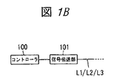
- the power conditioner 11, the charging / discharging device 21, the heat pump water heater 30, the ice making device 40, and the watt-hour meter 6 each include a controller 100 and a signal transmission unit 101 (see FIG. 1B).
- the signal transmission unit 101 performs data transmission using the power line L1 or the power supply lines L2 and L3 as a transmission path.
- the signal transmission unit 101 has a high frequency to an AC voltage or a DC voltage supplied via the power line L1 or the power supply lines L2 and L3. The signal voltage is superimposed.
- the technology for sharing the power feeding line and the data transmission transmission line is well known in the art, such as power line carrier communication, detailed description thereof will be omitted.
- the controller 100 includes a processor such as a CPU, and performs a process described later by executing a dedicated program on the processor. Each controller 100 is assigned a unique identification code, and the identification code becomes an address of each controller 100 in data transmission. Next, the operation of this embodiment will be described. First, the use of electric energy will be described.
- the power conditioner 11 stores the electric energy generated by the solar cell array 10 in the storage battery 20 by sending it to the charging / discharging device 21.
- the controller 100 of the charging / discharging device 21 constantly monitors the amount of electricity stored in the storage battery 20, and when the storage battery 20 is fully charged, a command to stop charging is sent from the signal transmission unit 101 to the controller 100 of the power conditioner 11 via the feeder line L3. Transmit to.
- the controller 100 of the power conditioner 11 supplies electric energy via the power supply line L3 until a charge stop command is received from the controller 100 of the charge / discharge device 21, and stops supplying the charge stop command when the charge stop command is received. To do. Furthermore, when there is surplus electrical energy that cannot be charged in the corresponding storage battery, the controller 100 of the power conditioner 11 sends a command for inquiring whether reverse power flow (power sale) to the AC power system 7 is possible from the signal transmission unit 101 through the power line L1. To the watt hour meter 6.
- the controller 100 of the watt hour meter 6 When the controller 100 of the watt hour meter 6 receives the command, it determines whether or not reverse power flow (power sale) is possible based on the current state of the AC power system 7, and the determination result is sent from the signal transmission unit 101 to the power line L 1. To the controller 100 of the power conditioner 11. When the system voltage of the AC power system 7 exceeds a predetermined voltage, or when the daily power sales amount (integrated power amount) exceeds a predetermined upper limit value, the watt-hour meter 6 is a reverse power flow. Judged as impossible, otherwise judged as reverse flow possible.
- the controller 100 of the power conditioner 11 transfers the electric energy generated by the solar cell array 10 to the AC power system 7 via the power line L1. Reverse current.
- the controller 100 of the power conditioner 11 is at least one of the controller 100 of the heat pump water heater 30 and the controller 100 of the ice making device 40.
- a command for instructing the start of operation is transmitted from the signal transmission unit 101 via the feeder line L2.
- the controller 100 of the heat pump water heater 30 or the controller 100 of the ice making device 40 receives an operation start command from the controller 100 of the power conditioner 11, the controller 100 starts the operation and consumes electric energy supplied via the power supply line L2. Hot water or ice is generated and stored in the hot water storage tank 31 or the heat storage tank 41.
- thermal energy can be interchanged between the systems. For example, since the performance of the solar cell array 10 and the storage battery 20 may decrease when the temperature decreases, if the solar cell array 10 and the storage battery 20 are warmed using the thermal energy stored in the hot water storage tank 31, the temperature is low. The performance degradation at the time of temperature can be suppressed.
- a temperature sensor 8 that detects the outside air temperature is connected to the controller 100 of the power conditioner 11 and the controller 100 of the charge / discharge device 21.
- the outside air temperature detected by the temperature sensor reaches a high temperature range (for example, 30 degrees Celsius or higher) or the maximum daily temperature, the ice making device 40 is controlled by the controller 100 of the power conditioner 11 and the controller 100 of the charge / discharge device 21.
- a cooling request command is transmitted from the signal transmission unit 101 to the controller 100.
- the controller 100 of the ice making device 40 that has received the command operates the circulation pump if the amount of heat stored in the heat storage tank 41 (the amount of ice) is full or has its own ice making capacity, and operates the heat storage tank 41.
- the cold air is circulated through the cold air pipe P2.
- the thermal energy of the cold air which circulates through the cold air piping P2 is supplied to the solar cell array 10 and the storage battery 20 through the radiator and cooled.
- the controller 100 of the power conditioner 11 and the controller 100 of the charging / discharging device 21 are used.
- the controller 100 transmits a heat insulation request command from the signal transmission unit 101.
- the controller 100 of the heat pump water heater 30 that has received the command operates the circulation pump and passes the hot water pipe 31 through the hot water pipe P1 if the hot water capacity of the hot water tank 31 is full or if its own hot water capacity is sufficient. Circulate hot water (heat energy). And the thermal energy of the hot water (warm water) circulating through the hot water pipe P1 is supplied to the solar cell array 10 and the storage battery 20 through the heat exchanger to be kept warm. As described above, in the energy management system according to the present embodiment, the surplus electrical energy generated by the photovoltaic power generation system 1 is reversely flowed, thereby saving energy and reducing the electricity bill.
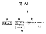
- the energy management system of the present embodiment includes a photovoltaic power generation system 1, a storage battery system 2, a heat pump hot water supply system 3, an ice thermal storage air conditioning system 4, a control device 5, and a watt hour meter 6. It consists of and. However, since the configuration other than the control device 5 is the same as that of the first embodiment, the same components are denoted by the same reference numerals and the description thereof is omitted. As shown in FIG. 2B, the control device 5 includes a controller 50, a signal transmission unit 51, a storage unit 52, and an environmental sensor 53. The signal transmission unit 51 performs data transmission using the power line L1 and the power supply lines L2 and L3 as transmission lines.
- the signal transmission unit 51 has a high frequency to an AC voltage or a DC voltage supplied via the power line L1 and the power supply lines L2 and L3.
- the signal voltage is superimposed.
- the environmental sensor 53 detects the outside air temperature, the outside air humidity, the amount of solar radiation, etc. periodically (for example, every several minutes to several tens of minutes), and outputs each detected value to the controller 50.
- the controller 50 includes a processor such as a CPU, and performs a process described later by executing a dedicated program on the processor. Further, the controller 50 can electrically rewrite the detection value data such as the outside air temperature, the outside air humidity, and the amount of solar radiation received from the environment sensor 53 together with a time stamp indicating the date and time when each detection value data is acquired.
- the controller 50 It memorize
- a unique identification code is assigned to the controller 50, and the identification code is an address of the controller 50 in data transmission.
- information on the surplus electrical energy and thermal energy is obtained from the controller 100 of each of the power conditioner 11, the charging / discharging device 21, the heat pump water heater 30, the ice making device 40, and the watt hour meter 6. Is transmitted.
- the controller 100 of the power conditioner 11 transmits measurement values such as the power generation amount and power generation efficiency (total system efficiency) of the solar cell array 10 and the temperature of the solar cell array 10 from the signal transmission unit 101 to the control device 5.
- the controller 100 of the charge / discharge device 21 transmits measured values such as the charge amount (or the ratio to the full charge) of the storage battery 20, the discharge amount, the charge / discharge efficiency, and the temperature of the storage battery 20 from the signal transmission unit 101 to the control device 5.
- the controller 100 of the heat pump water heater 30 transmits measured values such as the amount of hot water stored in the hot water storage tank 310 (or the ratio to the full water amount) and the amount of hot water supplied from the signal transmission unit 101 to the control device 5.
- the controller 100 of the ice making device 40 transmits measured values such as the amount of heat stored in the heat storage tank 41 (the amount of ice) and the amount of heat released (the amount of cold air supplied to the radiator 42) from the signal transmission unit 101 to the control device 5. ing.
- the controller 100 of the watt-hour meter 6 includes the amount of power received (purchased) from the AC power system 7 (system received power amount), the amount of power reversely flowed (sold) to the AC power system 7 (reverse power flow energy), A measurement value such as an achievement rate with respect to the upper limit value of the reverse flow power amount per day and information on whether reverse flow is possible are transmitted from the signal transmission unit 101 to the control device 5.
- information (data) such as measurement values transmitted from the signal transmission unit 101 of the power conditioner 11, the charge / discharge device 21, the heat pump water heater 30, the ice making device 40, and the watt hour meter 6 is stored.
- the signal is received by the signal transmission unit 101 and stored in the storage unit 52 together with the time stamp.
- the controller 50 of the control device 5 refers to the information (data) stored in the storage unit 52, and when one or more pieces of information (detected values, measured values, etc.) satisfy a predetermined condition, the heat pump water heater 30 A command for instructing start of operation is transmitted from the signal transmission unit 51 to the controller 100 or at least one of the controllers 100 of the ice making device 40 via the feeder line L2.
- the conditions are, for example, that the power generation amount of the solar cell array 10 is sufficiently large, the charge amount of the storage battery 20 is fully charged, the reverse power flow is impossible or the achievement rate of the reverse power flow amount is 100%, and the amount of solar radiation Exceeds the predetermined amount, and the amount of stored hot water or the amount of stored heat is below the threshold value.
- this condition is an example, and other conditions may be set.
- the controller 100 of the heat pump water heater 30 or the controller 100 of the ice making device 40 receives an operation start command from the controller 50 of the control device 5, the controller 100 starts the operation and consumes the electric energy supplied via the power supply line L ⁇ b> 2. Hot water or ice is generated and stored in the hot water storage tank 31 or the heat storage tank 41.
- the controller 50 of the control device 5 refers to the information (data) stored in the storage unit 52, and when one or more pieces of information (detected values, measured values, etc.) satisfy a predetermined condition, the heat pump water heater 30 A heat insulation request command is transmitted from the signal transmission unit 51 to the controller 100.
- the conditions are, for example, that the power generation efficiency is low, the temperature of the solar cell array 10 is lower than the lower limit value, and the amount of hot water stored in the hot water storage tank 31 remains 60% or more of the full water amount.
- the charging / discharging efficiency is low, the temperature of the storage battery 20 is lower than the lower limit value, and the hot water storage amount of the hot water storage tank 31 remains 60% or more of the full water amount.
- the controller 100 of the heat pump water heater 30 that has received the command from the control device 5 operates the circulation pump to circulate hot water (thermal energy) from the hot water storage tank 31 through the hot water pipe P1. And the thermal energy of the hot water (warm water) circulating through the hot water pipe P1 is supplied to the solar cell array 10 and the storage battery 20 via the heat exchanger and kept warm. Further, the power generation efficiency and the charge / discharge efficiency are low, the temperature of the solar cell array 10 or the temperature of the storage battery 20 exceeds the upper limit value, and the heat storage amount of the heat storage tank 41 remains 60% or more of the full ice amount. It is good also as conditions.
- the controller 50 of the control device 5 transmits a cooling request command from the signal transmission unit 51 to the controller 100 of the ice making device 40.
- the controller 100 of the ice making device 40 that has received the command from the control device 5 operates the circulation pump to circulate cold air from the heat storage tank 41 through the cold air pipe P2. And the thermal energy of the cold air which circulates through the cold air piping P2 is supplied to the solar cell array 10 and the storage battery 20 through the radiator and cooled.
- the energy management system of the present embodiment like the first embodiment, achieves energy saving and reduction of electric charges by causing the surplus electrical energy generated by the photovoltaic power generation system 1 to flow backward. be able to.
- the heat pump hot water supply system 3 and the ice heat storage air conditioning system 4 are operated, and a part of the surplus electrical energy is converted into heat energy and stored. Furthermore, when the outside air temperature reaches a certain temperature, surplus thermal energy can be utilized by supplying the cold air from the heat storage tank 41 or the hot water from the hot water storage tank 31 to the solar cell array 10 and the storage battery 20. Therefore, it is possible to efficiently generate and use electric energy and thermal energy to save energy. Furthermore, in the first embodiment, the controller 100 included in the power conditioner 11, the charging / discharging device 21, the heat pump water heater 30, the ice making device 40, and the watt-hour meter 6 performs distributed control. The device 5 performs centralized control.
- the distributed control method has an advantage that even if a new system is added, it is not necessary to change other existing systems.
- the control content (program) of the control device 5 needs to be changed, but there is an advantage that a dedicated program for each system becomes unnecessary.
Landscapes
- Engineering & Computer Science (AREA)
- Life Sciences & Earth Sciences (AREA)
- Sustainable Development (AREA)
- Chemical & Material Sciences (AREA)
- Mechanical Engineering (AREA)
- General Engineering & Computer Science (AREA)
- Sustainable Energy (AREA)
- Combustion & Propulsion (AREA)
- Thermal Sciences (AREA)
- Physics & Mathematics (AREA)
- Power Engineering (AREA)
- Manufacturing & Machinery (AREA)
- Chemical Kinetics & Catalysis (AREA)
- Electrochemistry (AREA)
- General Chemical & Material Sciences (AREA)
- Charge And Discharge Circuits For Batteries Or The Like (AREA)
- Supply And Distribution Of Alternating Current (AREA)
- Heat-Pump Type And Storage Water Heaters (AREA)
- Air Conditioning Control Device (AREA)
- Secondary Cells (AREA)
Abstract
Provided is an energy management system having: an interconnected photovoltaic system having a solar cell or a power conditioner for converting electrical energy generated from the solar cell to uniform electrical energy; a storage battery system having a storage battery or a charge/discharge device for storing electrical energy in the storage battery and discharging the accumulated electrical energy; a heat pump hot water supply system having a heat pump hot water supplier for using the electrical energy to generate hot water, and a hot water storage tank; and an ice thermal storage air conditioning system provided with an ice-making device for using the electrical energy to generate ice, and a thermal storage tank for storing the generated ice. The energy management system is characterised in the electrical energy generated by the photovoltaic system being stored in the storage battery, and the surplus electrical energy that cannot be discharged to the storage battery being consumed or stored by conversion to thermal energy in the heat pump hot water supply system or the ice storage air conditioning system.
Description
本発明は、住宅や事務所などで消費されるエネルギを管理するエネルギ管理システムに関する。
The present invention relates to an energy management system for managing energy consumed in a house or office.
従来、省エネルギ化を図るために、再生可能エネルギを電気エネルギに変換する太陽光発電システムや、大気中の熱エネルギを湯や氷として貯蔵し、給湯や冷暖房に利用するヒートポンプ給湯システムや氷蓄熱式空調システムなどが採用されている。なお、特許文献1には、電気料金の安い深夜の時間帯にヒートポンプ給湯機を運転して翌日に使用される湯を貯湯タンクに貯蔵することにより、電気料金の削減を図ったヒートポンプ給湯システムが記載されている。
特開平9−68369号公報(段落0016参照)
Conventionally, in order to save energy, a solar power generation system that converts renewable energy into electrical energy, a heat pump hot water supply system that stores thermal energy in the atmosphere as hot water or ice, and uses it for hot water supply or cooling and ice storage A type air conditioning system is adopted. Patent Document 1 discloses a heat pump hot water supply system that reduces electricity charges by operating a heat pump water heater in the midnight hours when electricity charges are low and storing hot water used the next day in a hot water storage tank. Are listed.
JP-A-9-68369 (see paragraph 0016)
ところで、従来は電気エネルギを生成する太陽光発電システムや熱エネルギを貯蔵するヒートポンプ給湯システム又は氷蓄熱式空調システムなどは、それぞれ単独で運転されていた。そのため、生成された電気エネルギや貯蔵されている熱エネルギが効率よく利用(消費)できない場合があった。
By the way, conventionally, a solar power generation system that generates electric energy, a heat pump hot water supply system that stores thermal energy, an ice heat storage air conditioning system, and the like have been operated independently. For this reason, the generated electrical energy and stored thermal energy may not be used (consumed) efficiently.
本発明は、上記課題に鑑みて為されたものであり、電気エネルギや熱エネルギの生成と利用を効率よく行って省エネルギ化を図ることのできるエネルギ管理システムを提供する。
本発明の一実施形態によるエネルギ管理システムは、太陽電池並びに当該太陽電池で生成される電気エネルギを所定の電気エネルギに変換するパワーコンディショナを有する系統連系形の太陽光発電システムと、蓄電池並びに当該蓄電池に電気エネルギを蓄電し且つ蓄電されている電気エネルギを放電させる充放電装置を有する蓄電池システムと、電気エネルギを消費して湯を生成するヒートポンプ給湯機並びに貯湯槽を有するヒートポンプ給湯システムと、電気エネルギを消費して氷を生成する製氷装置並びに生成された氷を蓄える蓄熱槽を有する氷蓄熱式の空調システムとを有し、前記太陽光発電システムで生成される電気エネルギが前記蓄電池に蓄電され、当該蓄電池に充電できない余剰の電気エネルギが前記ヒートポンプ給湯システム又は前記氷蓄熱式空調システムで熱エネルギに変換されて消費又は保存されることを特徴とする。
このエネルギ管理システムにおいて、前記パワーコンディショナは、前記充放電装置から電気エネルギの余剰分に関する情報が伝送され、当該情報に基づいて、前記太陽光発電システム又は前記蓄電池システムから前記ヒートポンプ給湯システム又は前記氷蓄熱式空調システムに余剰の電気エネルギが供給されることが好ましい。
このエネルギ管理システムにおいて、さらに外気温を検出する温度センサーが備われ、前記温度センサーの検出結果や前記ヒートポンプ給湯機及び前記製氷装置からの余剰の熱エネルギに関する情報に基づいて、前記ヒートポンプ給湯システム又は前記氷蓄熱式空調システムから前記太陽光発電システム又は前記蓄電池システムに余剰の熱エネルギが供給されることが好ましい。
このエネルギ管理システムにおいて、前記パワーコンディショナ及び前記充放電装置から電気エネルギの余剰分に関する情報が伝送され、当該情報に基づいて、前記太陽光発電システム又は前記蓄電池システムから前記ヒートポンプ給湯システム又は前記氷蓄熱式空調システムに余剰の電気エネルギを供給させる制御装置を備えることが好ましい。
このエネルギ管理システムにおいて、前記ヒートポンプ給湯機及び前記製氷装置から熱エネルギの余剰分に関する情報が伝送され、当該情報に基づいて、前記ヒートポンプ給湯システム又は前記氷蓄熱式空調システムから前記太陽光発電システム又は前記蓄電池システムに余剰の熱エネルギを供給させる制御装置を備えることが好ましい。
本発明によると、電気エネルギや熱エネルギの生成と利用を効率よく行って省エネルギ化を図ることができる。 The present invention has been made in view of the above problems, and provides an energy management system that can efficiently generate and use electrical energy and thermal energy to save energy.
An energy management system according to an embodiment of the present invention includes a solar cell, a grid-connected photovoltaic power generation system having a power conditioner that converts electric energy generated by the solar cell into predetermined electric energy, a storage battery, A storage battery system having a charge / discharge device for storing electrical energy in the storage battery and discharging the stored electrical energy; a heat pump water heater for generating hot water by consuming electrical energy; and a heat pump hot water supply system having a hot water storage tank; An ice making device that consumes electric energy to generate ice and an ice heat storage air conditioning system having a heat storage tank for storing the generated ice, and the electric energy generated by the solar power generation system is stored in the storage battery Excess electric energy that cannot be charged to the storage battery is generated by the heat pump hot water supply system. Or wherein said ice storage to be consumed or stored is converted into heat energy in the air conditioning system.
In this energy management system, the power conditioner is transmitted with information on surplus electrical energy from the charging / discharging device, and based on the information, from the solar power generation system or the storage battery system to the heat pump hot water supply system or the It is preferable that surplus electrical energy is supplied to the ice thermal storage air conditioning system.
In this energy management system, a temperature sensor for detecting an outside air temperature is further provided. Based on the detection result of the temperature sensor and information on excess heat energy from the heat pump water heater and the ice making device, the heat pump hot water system or It is preferable that surplus thermal energy is supplied to the photovoltaic power generation system or the storage battery system from the ice storage type air conditioning system.
In this energy management system, information on surplus electrical energy is transmitted from the power conditioner and the charging / discharging device, and based on the information, the heat pump hot water supply system or the ice from the solar power generation system or the storage battery system. It is preferable to include a control device that supplies excess electrical energy to the heat storage type air conditioning system.
In this energy management system, information on excess heat energy is transmitted from the heat pump water heater and the ice making device, and based on the information, from the heat pump hot water system or the ice regenerative air conditioning system to the solar power generation system or It is preferable to provide a control device that supplies surplus thermal energy to the storage battery system.
According to the present invention, it is possible to efficiently generate and use electric energy and heat energy to save energy.
本発明の目的および特徴は以下の添付図面と共に提供される今後の望ましい実施例の説明から明らかになる。
1Aは本発明の実施形態1によるエネルギ管理システムの構成図、1Bはブロック図である。
2Aは本発明の実施形態2によるエネルギ管理システムの構成図、2Bはブロック図である。
Objects and features of the present invention will become apparent from the following description of the preferred embodiment provided in conjunction with the accompanying drawings.
1A is a block diagram of an energy management system according to Embodiment 1 of the present invention, and 1B is a block diagram. 2A is a block diagram of an energy management system according to Embodiment 2 of the present invention, and 2B is a block diagram.
以下、戸建住宅向けのエネルギ管理システムに本発明の技術思想を適用した実施形態について説明する。但し、本発明に係るエネルギ管理システムは戸建住宅向けに限定されるものではなく、集合住宅や商業施設、オフィスビルなどにも設置することが可能である。
(実施形態1)
本実施形態のエネルギ管理システムは、図1Aに示すように太陽光発電システム1と、蓄電池システム2と、ヒートポンプ給湯システム3と、氷蓄熱式空調システム4と、電力量計6とで構成されている。
太陽光発電システムは、電力量計6を介して商用の交流電力系統7と接続された系統連系形のものであって、太陽エネルギを電気エネルギに変換する太陽電池アレイ10と、太陽電池アレイ10で生成(変換)される電気エネルギを負荷(住宅内の電気機器など)に適した所定の電気エネルギに変換するパワーコンディショナ11とを備えている。パワーコンディショナ11は、太陽電池アレイ10又は交流電力系統7から供給される電気エネルギを、給電線L2を介して住宅内の種々の負荷(ヒートポンプ給湯システム3と氷蓄熱式空調システム4を含む。以下同じ。)に供給している。また、パワーコンディショナ11は、後述するように電気エネルギの余剰分を、電力線L1を介して交流電力系統7に逆潮流(売電)することもできる。
蓄電池システム2は、リチウムイオン電池などの蓄電池20と、パワーコンディショナ11から給電線L3を介して供給される電気エネルギを蓄電池20に充電するとともに、蓄電池20に蓄えられた電気エネルギを放電させてパワーコンディショナ11経由で負荷に供給する充放電装置21とを備えている。
ヒートポンプ給湯システム3は、給電線L2を介して供給される電気エネルギを消費して湯を生成するヒートポンプ給湯機30と、ヒートポンプ給湯機30で生成される湯を貯蔵する貯湯槽31とを備えている。なお、貯湯槽31には温水配管P1が接続されており、図示しない循環ポンプによって貯湯槽31に蓄えられた湯(熱エネルギ)が温水配管P1に循環されるようになっている。そして、太陽電池アレイ10並びに蓄電池20の近傍に熱交換器(図示せず)が設置され、温水配管P1を循環する湯(温水)の熱エネルギが熱交換器を介して供給されることで太陽電池アレイ10や蓄電池20が保温されるようになっている。
氷蓄熱式空調システム4は、給電線L2を介して供給される電気エネルギを消費して氷を生成する製氷装置40と、生成された氷を蓄える蓄熱槽41と、蓄熱槽41に蓄えられた氷(熱エネルギ)を放熱して室内を冷房する放熱器42とを備えている。なお、蓄熱槽41には冷気配管P2が接続されており、図示しない循環ポンプによって蓄熱槽41に蓄えられた熱エネルギ(冷気)が冷気配管P2に循環されるようになっている。そして、太陽電池アレイ10並びに蓄電池20の近傍に放熱器(図示せず)が設置され、冷気配管P2を循環する冷気の熱エネルギが放熱器を介して供給されることで太陽電池アレイ10や蓄電池20が冷却されるようになっている。
電力量計6は、交流電力系統7からパワーコンディショナ11に流れる電力量(買電電力量)と、パワーコンディショナ11から交流電力系統7に逆潮流する電力量(売電電力量)とを個別に計測する機能を有している。
ここで、パワーコンディショナ11並びに充放電装置21、ヒートポンプ給湯機30、製氷装置40、電力量計6は、それぞれコントローラ100と信号伝送部101を具備している(図1B参照)。信号伝送部101は、電力線L1又は給電線L2,L3を伝送路としてデータ伝送を行うものであって、例えば、電力線L1や給電線L2,L3を介して供給される交流電圧や直流電圧に高周波の信号電圧を重畳している。但し、このように給電用の線路とデータ伝送用の伝送路とを共用する技術については、例えば、電力線搬送通信のように従来周知であるから詳細な説明は省略する。コントローラ100はCPUなどのプロセッサからなり、当該プロセッサでそれぞれ専用のプログラムを実行することによって、後述する処理を行っている。なお、各コントローラ100には固有の識別符号が割り当てられており、当該識別符号がデータ伝送における各コントローラ100のアドレスとなる。
次に、本実施形態の動作を説明する。まず、電気エネルギの利用について説明する。
パワーコンディショナ11は、太陽電池アレイ10で生成される電気エネルギを充放電装置21に送出することで蓄電池20に蓄電させる。充放電装置21のコントローラ100は蓄電池20の蓄電量を常に監視しており、蓄電池20が満充電になると充電停止のコマンドを信号伝送部101より給電線L3を介してパワーコンディショナ11のコントローラ100に伝送する。一方、パワーコンディショナ11のコントローラ100は、充放電装置21のコントローラ100から充電停止のコマンドを受け取るまでは給電線L3を介して電気エネルギを供給し、充電停止のコマンドを受け取るとその供給を停止する。さらに、該当蓄電池に充電できない余剰の電気エネルギがある場合、パワーコンディショナ11のコントローラ100は、交流電力系統7への逆潮流(売電)の可否を問い合わせるコマンドを信号伝送部101より電力線L1を介して電力量計6に伝送する。電力量計6のコントローラ100は、前記コマンドを受け取ると、現在の交流電力系統7の状態に基づいて逆潮流(売電)の可否を判断し、その判断結果を信号伝送部101より電力線L1を介してパワーコンディショナ11のコントローラ100に伝送する。電力量計6は、交流電力系統7の系統電圧が所定の電圧を超えているとき、あるいは1日の売電量(積算電力量)が所定の上限値を超えているときは、何れも逆潮流不可と判断し、それ以外のときは逆潮流可と判断する。
パワーコンディショナ11のコントローラ100は、電力量計6のコントローラ100から受け取った判断結果が逆潮流可であれば、太陽電池アレイ10で生成される電気エネルギを電力線L1を介して交流電力系統7に逆潮流する。一方、電力量計6のコントローラ100から受け取った判断結果が逆潮流不可であれば、パワーコンディショナ11のコントローラ100は、ヒートポンプ給湯機30のコントローラ100又は製氷装置40のコントローラ100の少なくとも何れか一方に対して、運転開始を指示するコマンドを信号伝送部101より給電線L2を介して伝送する。
ヒートポンプ給湯機30のコントローラ100又は製氷装置40のコントローラ100は、パワーコンディショナ11のコントローラ100から運転開始のコマンドを受け取ると運転を開始し、給電線L2を介して供給される電気エネルギを消費して湯又は氷を生成し、貯湯槽31又は蓄熱槽41に貯蔵する。
また、本実施形態では電気エネルギだけでなく、熱エネルギについても各システム間で融通し合うことができる。例えば、気温が低下すると太陽電池アレイ10や蓄電池20の性能が低下することがあるので、貯湯槽31に貯蔵された熱エネルギを利用して太陽電池アレイ10や蓄電池20を暖めてやれば、低気温時の性能低下を抑制することができる。反対に、気温が上昇すると太陽電池アレイ10や蓄電池20の性能が低下することがあるので、蓄熱槽41に貯蔵された熱エネルギを利用して太陽電池アレイ10や蓄電池20を冷却してやれば、高気温時の性能低下を抑制することができる。
次に、熱エネルギの利用について説明する。パワーコンディショナ11のコントローラ100並びに充放電装置21のコントローラ100には、外気温を検出する温度センサ8が接続されている。そして、温度センサで検出される外気温が高温域(例えば、摂氏30度以上)または一日の最高気温に達すると、パワーコンディショナ11のコントローラ100並びに充放電装置21のコントローラ100から製氷装置40のコントローラ100に対して、冷却要求のコマンドが信号伝送部101より伝送される。当該コマンドを受け取った製氷装置40のコントローラ100は、蓄熱槽41の蓄熱量(氷の量)が満杯であるか、あるいは自身の製氷能力に余裕があれば、循環ポンプを動作させて蓄熱槽41から冷気配管P2を通して冷気を循環させる。
そして、冷気配管P2を循環する冷気の熱エネルギが放熱器を介して太陽電池アレイ10や蓄電池20に供給されて冷却されることになる。
一方、温度センサで検出される外気温が低温域(例えば、摂氏0度以下)または一日最低気温に達すると、パワーコンディショナ11のコントローラ100並びに充放電装置21のコントローラ100からヒートポンプ給湯機30のコントローラ100に対して、保温要求のコマンドが信号伝送部101より伝送される。当該コマンドを受け取ったヒートポンプ給湯機30のコントローラ100は、貯湯槽31の湯量が満杯であるか、あるいは自身の給湯能力に余裕があれば、循環ポンプを動作させて貯湯槽31から温水配管P1を通して湯(熱エネルギ)を循環させる。そして、温水配管P1を循環する湯(温水)の熱エネルギが熱交換器を介して太陽電池アレイ10や蓄電池20に供給されて保温されることになる。
このように本実施形態のエネルギ管理システムでは、太陽光発電システム1で生成される電気エネルギの余剰分が逆潮流されることで省エネルギ化と電気料金の削減を図ることができる。しかも、逆潮流ができないときはヒートポンプ給湯システム3や氷蓄熱式空調システム4を運転して電気エネルギの余剰分の一部(ヒートポンプ給湯機30や製氷装置40で消費される電力を差し引いた残りの分)が熱エネルギに変換されて貯蔵される。さらに、外気温が一定の温度に達すると、蓄熱槽41からの冷気または貯湯槽からの湯を太陽電池アレイ10および蓄電池20に供給することで余剰の熱エネルギを利用することができる。したがって、電気エネルギや熱エネルギの生成と利用を効率よく行って省エネルギ化を図ることができる。
(実施形態2)
本実施形態のエネルギ管理システムは、図2Aに示すように太陽光発電システム1と、蓄電池システム2と、ヒートポンプ給湯システム3と、氷蓄熱式空調システム4と、制御装置5と、電力量計6とで構成されている。但し、制御装置5以外の構成については、実施形態1と共通であるから、共通の構成要素には同一の符号を付して説明を省略する。
制御装置5は、図2Bに示すようにコントローラ50と信号伝送部51と記憶部52と環境センサ53とを具備している。信号伝送部51は、電力線L1並びに給電線L2,L3を伝送路としてデータ伝送を行うものであって、例えば、電力線L1並びに給電線L2,L3を介して供給される交流電圧や直流電圧に高周波の信号電圧を重畳している。環境センサ53は、外気温や外気湿度、日射量などを定期的(例えば、数分~数十分毎)に検出し、それぞれの検出値をコントローラ50に出力する。コントローラ50はCPUなどのプロセッサからなり、当該プロセッサで専用のプログラムを実行することによって、後述する処理を行っている。またコントローラ50は、環境センサ53から受け取る外気温、外気湿度、日射量などの検出値のデータを、それぞれの検出値データが取得された日付及び時刻を示すタイムスタンプとともに、電気的に書換可能な不揮発性半導体メモリ(例えば、フラッシュメモリなど)からなる記憶部52に記憶する。なお、コントローラ50には固有の識別符号が割り当てられており、当該識別符号がデータ伝送におけるコントローラ50のアドレスとなる。
本実施形態においては、パワーコンディショナ11、充放電装置21、ヒートポンプ給湯機30、製氷装置40、電力量計6のそれぞれのコントローラ100より、電気エネルギや熱エネルギの余剰分に関する情報が制御装置5に伝送される。パワーコンディショナ11のコントローラ100は、太陽電池アレイ10の発電量や発電効率(総合システム効率)、太陽電池アレイ10の温度などの計測値を信号伝送部101より制御装置5へ伝送している。充放電装置21のコントローラ100は、蓄電池20の充電量(あるいは満充電に対する割合)や放電量、充放電の効率、蓄電池20の温度などの計測値を信号伝送部101より制御装置5へ伝送している。ヒートポンプ給湯機30のコントローラ100は、貯湯槽310の貯湯量(あるいは満水量に対する割合)や給湯量などの計測値を信号伝送部101より制御装置5へ伝送している。製氷装置40のコントローラ100は、蓄熱槽41の蓄熱量(氷の量)や放熱量(放熱器42に供給される冷気の量)などの計測値を信号伝送部101より制御装置5へ伝送している。電力量計6のコントローラ100は、交流電力系統7から受電(買電)した電力量(系統受電電力量)や交流電力系統7へ逆潮流(売電)した電力量(逆潮流電力量)、1日の逆潮流電力量の上限値に対する達成率などの計測値及び逆潮流の可否の情報を信号伝送部101より制御装置5へ伝送している。
一方、制御装置5においては、パワーコンディショナ11、充放電装置21、ヒートポンプ給湯機30、製氷装置40、電力量計6の信号伝送部101から伝送されてくる計測値などの情報(データ)が信号伝送部101で受信され、タイムスタンプとともに記憶部52に記憶される。
次に、本実施形態の動作を説明する。まず、電気エネルギの利用について説明する。
制御装置5のコントローラ50は、記憶部52に記憶している情報(データ)を参照し、1乃至複数の情報(検出値や計測値等)が所定の条件を満たす場合、ヒートポンプ給湯機30のコントローラ100又は製氷装置40のコントローラ100の少なくとも何れか一方に対して、運転開始を指示するコマンドを信号伝送部51より給電線L2を介して伝送する。前記条件とは、例えば、太陽電池アレイ10の発電量が充分に多く、蓄電池20の充電量が満充電であり、逆潮流が不可又は逆潮流電力量の達成率が100%であり、日射量が所定量を超え、且つ貯湯量又は蓄熱量がしきい値を下回っていることである。但し、この条件は一例であって、その他の条件が設定される場合もある。
ヒートポンプ給湯機30のコントローラ100又は製氷装置40のコントローラ100は、制御装置5のコントローラ50から運転開始のコマンドを受け取ると運転を開始し、給電線L2を介して供給される電気エネルギを消費して湯又は氷を生成し、貯湯槽31又は蓄熱槽41に貯蔵する。
次に、熱エネルギの利用について説明する。制御装置5のコントローラ50は、記憶部52に記憶している情報(データ)を参照し、1乃至複数の情報(検出値や計測値等)が所定の条件を満たす場合、ヒートポンプ給湯機30のコントローラ100に対して保温要求のコマンドを信号伝送部51より伝送する。前記条件とは、例えば、発電効率が低く且つ太陽電池アレイ10の温度が下限値を下回っており、さらに貯湯槽31の貯湯量が満水量の60%以上残っていることである。あるいは、充放電の効率が低く且つ蓄電池20の温度が下限値を下回っており、さらに貯湯槽31の貯湯量が満水量の60%以上残っていることである。但し、これらの条件は一例であって、その他の条件が設定される場合もある。
制御装置5からコマンドを受け取ったヒートポンプ給湯機30のコントローラ100は、循環ポンプを動作させて貯湯槽31から温水配管P1を通して湯(熱エネルギ)を循環させる。そして、温水配管P1を循環する湯(温水)の熱エネルギが熱交換器を介して太陽電池アレイ10や蓄電池20に供給されて保温される。
また、発電効率や充放電効率が低く且つ太陽電池アレイ10の温度又は蓄電池20の温度が上限値を上回っており、さらに蓄熱槽41の蓄熱量が満氷量の60%以上残っていることを条件としてもよい。そして、この条件が満たされた場合、制御装置5のコントローラ50は、製氷装置40のコントローラ100に対して冷却要求のコマンドを信号伝送部51より伝送する。
制御装置5からコマンドを受け取った製氷装置40のコントローラ100は、循環ポンプを動作させて蓄熱槽41から冷気配管P2を通して冷気を循環させる。そして、冷気配管P2を循環する冷気の熱エネルギが放熱器を介して太陽電池アレイ10や蓄電池20に供給されて冷却される。
このように本実施形態のエネルギ管理システムは、実施形態1と同様に、太陽光発電システム1で生成される電気エネルギの余剰分が逆潮流されることで省エネルギ化と電気料金の削減を図ることができる。しかも、逆潮流ができないときはヒートポンプ給湯システム3や氷蓄熱式空調システム4を運転して電気エネルギの余剰分の一部が熱エネルギに変換されて貯蔵される。さらに、外気温が一定の温度に達すると、蓄熱槽41からの冷気または貯湯槽31からの湯を太陽電池アレイ10および蓄電池20に供給することで余剰の熱エネルギを利用することができる。したがって、電気エネルギや熱エネルギの生成と利用を効率よく行って省エネルギ化を図ることができる。さらに、実施形態1では、パワーコンディショナ11、充放電装置21、ヒートポンプ給湯機30、製氷装置40、電力量計6が具備するコントローラ100が分散制御を行っているが、本実施形態では、制御装置5が集中制御を行っている。分散制御方式では、新たなシステムが追加されても他の既存のシステムに変更を加える必要が無いという利点がある。一方、集中制御方式では、新たなシステムが追加されると制御装置5の制御内容(プログラム)の変更が必要になるが、個々のシステム毎の専用プログラムが不要になるという利点がある。
以上のように本発明の望ましい実施形態を説明したが、本発明はこれら特定の実施形態に限らず、後続する請求範囲内で多様に変更および修正が行われることが可能であり、それも本発明の範囲内に属すると言える。 Hereinafter, an embodiment in which the technical idea of the present invention is applied to an energy management system for a detached house will be described. However, the energy management system according to the present invention is not limited to a detached house, and can be installed in an apartment house, a commercial facility, an office building, or the like.
(Embodiment 1)
As shown in FIG. 1A, the energy management system of the present embodiment includes a photovoltaicpower generation system 1, a storage battery system 2, a heat pump hot water supply system 3, an ice thermal storage air conditioning system 4, and a watt hour meter 6. Yes.
The solar power generation system is a grid-connected type connected to a commercialAC power system 7 via a watt-hour meter 6, and includes a solar cell array 10 that converts solar energy into electric energy, and a solar cell array. And a power conditioner 11 that converts electrical energy generated (converted) at 10 into predetermined electrical energy suitable for a load (such as an electrical device in a house). The power conditioner 11 includes various loads (a heat pump hot water supply system 3 and an ice regenerative air conditioning system 4) in a house through electric power supplied from the solar cell array 10 or the AC power system 7 via a power supply line L2. The same shall apply hereinafter). Further, the power conditioner 11 can reversely flow (sell power) the surplus electrical energy to the AC power system 7 via the power line L1, as will be described later.
Thestorage battery system 2 charges the storage battery 20 with the storage battery 20 such as a lithium ion battery and the electric energy supplied from the power conditioner 11 via the power supply line L3, and discharges the electric energy stored in the storage battery 20. And a charge / discharge device 21 that supplies the load via the power conditioner 11.
The heat pump hot water supply system 3 includes a heatpump water heater 30 that generates hot water by consuming electric energy supplied via the power supply line L2, and a hot water storage tank 31 that stores hot water generated by the heat pump water heater 30. Yes. A hot water pipe P1 is connected to the hot water tank 31, and hot water (thermal energy) stored in the hot water tank 31 is circulated to the hot water pipe P1 by a circulation pump (not shown). A heat exchanger (not shown) is installed in the vicinity of the solar cell array 10 and the storage battery 20, and the heat energy of hot water (warm water) circulating through the hot water pipe P1 is supplied via the heat exchanger. The battery array 10 and the storage battery 20 are kept warm.
The ice heat storage air conditioning system 4 is stored in the ice making device 40 that consumes electric energy supplied via the power supply line L2 to generate ice, theheat storage tank 41 that stores the generated ice, and the heat storage tank 41. And a radiator 42 for radiating ice (heat energy) to cool the room. The heat storage tank 41 is connected with a cold air pipe P2, and heat energy (cold air) stored in the heat storage tank 41 by a circulation pump (not shown) is circulated to the cold air pipe P2. Then, a radiator (not shown) is installed in the vicinity of the solar cell array 10 and the storage battery 20, and the thermal energy of the cold air circulating through the cold air pipe P2 is supplied via the radiator, so that the solar cell array 10 and the storage battery. 20 is cooled.
The watt-hour meter 6 individually determines the amount of power flowing from the AC power system 7 to the power conditioner 11 (the amount of purchased power) and the amount of power flowing back from the power conditioner 11 to the AC power system 7 (the amount of power sold). Has the function to measure.
Here, the power conditioner 11, the charging /discharging device 21, the heat pump water heater 30, the ice making device 40, and the watt-hour meter 6 each include a controller 100 and a signal transmission unit 101 (see FIG. 1B). The signal transmission unit 101 performs data transmission using the power line L1 or the power supply lines L2 and L3 as a transmission path. For example, the signal transmission unit 101 has a high frequency to an AC voltage or a DC voltage supplied via the power line L1 or the power supply lines L2 and L3. The signal voltage is superimposed. However, since the technology for sharing the power feeding line and the data transmission transmission line is well known in the art, such as power line carrier communication, detailed description thereof will be omitted. The controller 100 includes a processor such as a CPU, and performs a process described later by executing a dedicated program on the processor. Each controller 100 is assigned a unique identification code, and the identification code becomes an address of each controller 100 in data transmission.
Next, the operation of this embodiment will be described. First, the use of electric energy will be described.
The power conditioner 11 stores the electric energy generated by thesolar cell array 10 in the storage battery 20 by sending it to the charging / discharging device 21. The controller 100 of the charging / discharging device 21 constantly monitors the amount of electricity stored in the storage battery 20, and when the storage battery 20 is fully charged, a command to stop charging is sent from the signal transmission unit 101 to the controller 100 of the power conditioner 11 via the feeder line L3. Transmit to. On the other hand, the controller 100 of the power conditioner 11 supplies electric energy via the power supply line L3 until a charge stop command is received from the controller 100 of the charge / discharge device 21, and stops supplying the charge stop command when the charge stop command is received. To do. Furthermore, when there is surplus electrical energy that cannot be charged in the corresponding storage battery, the controller 100 of the power conditioner 11 sends a command for inquiring whether reverse power flow (power sale) to the AC power system 7 is possible from the signal transmission unit 101 through the power line L1. To the watt hour meter 6. When the controller 100 of the watt hour meter 6 receives the command, it determines whether or not reverse power flow (power sale) is possible based on the current state of the AC power system 7, and the determination result is sent from the signal transmission unit 101 to the power line L 1. To the controller 100 of the power conditioner 11. When the system voltage of the AC power system 7 exceeds a predetermined voltage, or when the daily power sales amount (integrated power amount) exceeds a predetermined upper limit value, the watt-hour meter 6 is a reverse power flow. Judged as impossible, otherwise judged as reverse flow possible.
If the determination result received from thecontroller 100 of the watt-hour meter 6 allows reverse power flow, the controller 100 of the power conditioner 11 transfers the electric energy generated by the solar cell array 10 to the AC power system 7 via the power line L1. Reverse current. On the other hand, if the determination result received from the controller 100 of the watt hour meter 6 is not possible to reverse flow, the controller 100 of the power conditioner 11 is at least one of the controller 100 of the heat pump water heater 30 and the controller 100 of the ice making device 40. On the other hand, a command for instructing the start of operation is transmitted from the signal transmission unit 101 via the feeder line L2.
When thecontroller 100 of the heat pump water heater 30 or the controller 100 of the ice making device 40 receives an operation start command from the controller 100 of the power conditioner 11, the controller 100 starts the operation and consumes electric energy supplied via the power supply line L2. Hot water or ice is generated and stored in the hot water storage tank 31 or the heat storage tank 41.
In this embodiment, not only electrical energy but also thermal energy can be interchanged between the systems. For example, since the performance of thesolar cell array 10 and the storage battery 20 may decrease when the temperature decreases, if the solar cell array 10 and the storage battery 20 are warmed using the thermal energy stored in the hot water storage tank 31, the temperature is low. The performance degradation at the time of temperature can be suppressed. On the other hand, when the temperature rises, the performance of the solar cell array 10 and the storage battery 20 may be reduced. Therefore, if the solar cell array 10 and the storage battery 20 are cooled using the thermal energy stored in the heat storage tank 41, the temperature increases. The performance degradation at the time of temperature can be suppressed.
Next, utilization of heat energy will be described. Atemperature sensor 8 that detects the outside air temperature is connected to the controller 100 of the power conditioner 11 and the controller 100 of the charge / discharge device 21. When the outside air temperature detected by the temperature sensor reaches a high temperature range (for example, 30 degrees Celsius or higher) or the maximum daily temperature, the ice making device 40 is controlled by the controller 100 of the power conditioner 11 and the controller 100 of the charge / discharge device 21. A cooling request command is transmitted from the signal transmission unit 101 to the controller 100. The controller 100 of the ice making device 40 that has received the command operates the circulation pump if the amount of heat stored in the heat storage tank 41 (the amount of ice) is full or has its own ice making capacity, and operates the heat storage tank 41. The cold air is circulated through the cold air pipe P2.
And the thermal energy of the cold air which circulates through the cold air piping P2 is supplied to thesolar cell array 10 and the storage battery 20 through the radiator and cooled.
On the other hand, when the outside air temperature detected by the temperature sensor reaches a low temperature range (for example, 0 degrees Celsius or less) or the daily minimum air temperature, thecontroller 100 of the power conditioner 11 and the controller 100 of the charging / discharging device 21 are used. The controller 100 transmits a heat insulation request command from the signal transmission unit 101. The controller 100 of the heat pump water heater 30 that has received the command operates the circulation pump and passes the hot water pipe 31 through the hot water pipe P1 if the hot water capacity of the hot water tank 31 is full or if its own hot water capacity is sufficient. Circulate hot water (heat energy). And the thermal energy of the hot water (warm water) circulating through the hot water pipe P1 is supplied to the solar cell array 10 and the storage battery 20 through the heat exchanger to be kept warm.
As described above, in the energy management system according to the present embodiment, the surplus electrical energy generated by the photovoltaicpower generation system 1 is reversely flowed, thereby saving energy and reducing the electricity bill. In addition, when reverse power flow is not possible, the heat pump hot water supply system 3 and the ice thermal storage air conditioning system 4 are operated, and a part of the surplus electric energy (remaining electric power consumed by the heat pump water heater 30 and the ice making device 40 is subtracted Min) is converted to thermal energy and stored. Further, when the outside air temperature reaches a certain temperature, surplus thermal energy can be utilized by supplying cold air from the heat storage tank 41 or hot water from the hot water storage tank to the solar cell array 10 and the storage battery 20. Therefore, it is possible to efficiently generate and use electric energy and heat energy to save energy.
(Embodiment 2)
As shown in FIG. 2A, the energy management system of the present embodiment includes a photovoltaicpower generation system 1, a storage battery system 2, a heat pump hot water supply system 3, an ice thermal storage air conditioning system 4, a control device 5, and a watt hour meter 6. It consists of and. However, since the configuration other than the control device 5 is the same as that of the first embodiment, the same components are denoted by the same reference numerals and the description thereof is omitted.
As shown in FIG. 2B, thecontrol device 5 includes a controller 50, a signal transmission unit 51, a storage unit 52, and an environmental sensor 53. The signal transmission unit 51 performs data transmission using the power line L1 and the power supply lines L2 and L3 as transmission lines. For example, the signal transmission unit 51 has a high frequency to an AC voltage or a DC voltage supplied via the power line L1 and the power supply lines L2 and L3. The signal voltage is superimposed. The environmental sensor 53 detects the outside air temperature, the outside air humidity, the amount of solar radiation, etc. periodically (for example, every several minutes to several tens of minutes), and outputs each detected value to the controller 50. The controller 50 includes a processor such as a CPU, and performs a process described later by executing a dedicated program on the processor. Further, the controller 50 can electrically rewrite the detection value data such as the outside air temperature, the outside air humidity, and the amount of solar radiation received from the environment sensor 53 together with a time stamp indicating the date and time when each detection value data is acquired. It memorize | stores in the memory | storage part 52 which consists of non-volatile semiconductor memories (for example, flash memory etc.). A unique identification code is assigned to the controller 50, and the identification code is an address of the controller 50 in data transmission.
In the present embodiment, information on the surplus electrical energy and thermal energy is obtained from thecontroller 100 of each of the power conditioner 11, the charging / discharging device 21, the heat pump water heater 30, the ice making device 40, and the watt hour meter 6. Is transmitted. The controller 100 of the power conditioner 11 transmits measurement values such as the power generation amount and power generation efficiency (total system efficiency) of the solar cell array 10 and the temperature of the solar cell array 10 from the signal transmission unit 101 to the control device 5. The controller 100 of the charge / discharge device 21 transmits measured values such as the charge amount (or the ratio to the full charge) of the storage battery 20, the discharge amount, the charge / discharge efficiency, and the temperature of the storage battery 20 from the signal transmission unit 101 to the control device 5. ing. The controller 100 of the heat pump water heater 30 transmits measured values such as the amount of hot water stored in the hot water storage tank 310 (or the ratio to the full water amount) and the amount of hot water supplied from the signal transmission unit 101 to the control device 5. The controller 100 of the ice making device 40 transmits measured values such as the amount of heat stored in the heat storage tank 41 (the amount of ice) and the amount of heat released (the amount of cold air supplied to the radiator 42) from the signal transmission unit 101 to the control device 5. ing. The controller 100 of the watt-hour meter 6 includes the amount of power received (purchased) from the AC power system 7 (system received power amount), the amount of power reversely flowed (sold) to the AC power system 7 (reverse power flow energy), A measurement value such as an achievement rate with respect to the upper limit value of the reverse flow power amount per day and information on whether reverse flow is possible are transmitted from the signal transmission unit 101 to the control device 5.
On the other hand, in thecontrol device 5, information (data) such as measurement values transmitted from the signal transmission unit 101 of the power conditioner 11, the charge / discharge device 21, the heat pump water heater 30, the ice making device 40, and the watt hour meter 6 is stored. The signal is received by the signal transmission unit 101 and stored in the storage unit 52 together with the time stamp.
Next, the operation of this embodiment will be described. First, the use of electric energy will be described.
Thecontroller 50 of the control device 5 refers to the information (data) stored in the storage unit 52, and when one or more pieces of information (detected values, measured values, etc.) satisfy a predetermined condition, the heat pump water heater 30 A command for instructing start of operation is transmitted from the signal transmission unit 51 to the controller 100 or at least one of the controllers 100 of the ice making device 40 via the feeder line L2. The conditions are, for example, that the power generation amount of the solar cell array 10 is sufficiently large, the charge amount of the storage battery 20 is fully charged, the reverse power flow is impossible or the achievement rate of the reverse power flow amount is 100%, and the amount of solar radiation Exceeds the predetermined amount, and the amount of stored hot water or the amount of stored heat is below the threshold value. However, this condition is an example, and other conditions may be set.
When thecontroller 100 of the heat pump water heater 30 or the controller 100 of the ice making device 40 receives an operation start command from the controller 50 of the control device 5, the controller 100 starts the operation and consumes the electric energy supplied via the power supply line L <b> 2. Hot water or ice is generated and stored in the hot water storage tank 31 or the heat storage tank 41.
Next, utilization of heat energy will be described. Thecontroller 50 of the control device 5 refers to the information (data) stored in the storage unit 52, and when one or more pieces of information (detected values, measured values, etc.) satisfy a predetermined condition, the heat pump water heater 30 A heat insulation request command is transmitted from the signal transmission unit 51 to the controller 100. The conditions are, for example, that the power generation efficiency is low, the temperature of the solar cell array 10 is lower than the lower limit value, and the amount of hot water stored in the hot water storage tank 31 remains 60% or more of the full water amount. Alternatively, the charging / discharging efficiency is low, the temperature of the storage battery 20 is lower than the lower limit value, and the hot water storage amount of the hot water storage tank 31 remains 60% or more of the full water amount. However, these conditions are merely examples, and other conditions may be set.
Thecontroller 100 of the heat pump water heater 30 that has received the command from the control device 5 operates the circulation pump to circulate hot water (thermal energy) from the hot water storage tank 31 through the hot water pipe P1. And the thermal energy of the hot water (warm water) circulating through the hot water pipe P1 is supplied to the solar cell array 10 and the storage battery 20 via the heat exchanger and kept warm.
Further, the power generation efficiency and the charge / discharge efficiency are low, the temperature of thesolar cell array 10 or the temperature of the storage battery 20 exceeds the upper limit value, and the heat storage amount of the heat storage tank 41 remains 60% or more of the full ice amount. It is good also as conditions. When this condition is satisfied, the controller 50 of the control device 5 transmits a cooling request command from the signal transmission unit 51 to the controller 100 of the ice making device 40.
Thecontroller 100 of the ice making device 40 that has received the command from the control device 5 operates the circulation pump to circulate cold air from the heat storage tank 41 through the cold air pipe P2. And the thermal energy of the cold air which circulates through the cold air piping P2 is supplied to the solar cell array 10 and the storage battery 20 through the radiator and cooled.
As described above, the energy management system of the present embodiment, like the first embodiment, achieves energy saving and reduction of electric charges by causing the surplus electrical energy generated by the photovoltaicpower generation system 1 to flow backward. be able to. In addition, when the reverse power flow is not possible, the heat pump hot water supply system 3 and the ice heat storage air conditioning system 4 are operated, and a part of the surplus electrical energy is converted into heat energy and stored. Furthermore, when the outside air temperature reaches a certain temperature, surplus thermal energy can be utilized by supplying the cold air from the heat storage tank 41 or the hot water from the hot water storage tank 31 to the solar cell array 10 and the storage battery 20. Therefore, it is possible to efficiently generate and use electric energy and thermal energy to save energy. Furthermore, in the first embodiment, the controller 100 included in the power conditioner 11, the charging / discharging device 21, the heat pump water heater 30, the ice making device 40, and the watt-hour meter 6 performs distributed control. The device 5 performs centralized control. The distributed control method has an advantage that even if a new system is added, it is not necessary to change other existing systems. On the other hand, in the centralized control method, when a new system is added, the control content (program) of the control device 5 needs to be changed, but there is an advantage that a dedicated program for each system becomes unnecessary.
Although the preferred embodiments of the present invention have been described above, the present invention is not limited to these specific embodiments, and various changes and modifications can be made within the scope of the claims that follow. It can be said that it belongs to the scope of the invention.
(実施形態1)
本実施形態のエネルギ管理システムは、図1Aに示すように太陽光発電システム1と、蓄電池システム2と、ヒートポンプ給湯システム3と、氷蓄熱式空調システム4と、電力量計6とで構成されている。
太陽光発電システムは、電力量計6を介して商用の交流電力系統7と接続された系統連系形のものであって、太陽エネルギを電気エネルギに変換する太陽電池アレイ10と、太陽電池アレイ10で生成(変換)される電気エネルギを負荷(住宅内の電気機器など)に適した所定の電気エネルギに変換するパワーコンディショナ11とを備えている。パワーコンディショナ11は、太陽電池アレイ10又は交流電力系統7から供給される電気エネルギを、給電線L2を介して住宅内の種々の負荷(ヒートポンプ給湯システム3と氷蓄熱式空調システム4を含む。以下同じ。)に供給している。また、パワーコンディショナ11は、後述するように電気エネルギの余剰分を、電力線L1を介して交流電力系統7に逆潮流(売電)することもできる。
蓄電池システム2は、リチウムイオン電池などの蓄電池20と、パワーコンディショナ11から給電線L3を介して供給される電気エネルギを蓄電池20に充電するとともに、蓄電池20に蓄えられた電気エネルギを放電させてパワーコンディショナ11経由で負荷に供給する充放電装置21とを備えている。
ヒートポンプ給湯システム3は、給電線L2を介して供給される電気エネルギを消費して湯を生成するヒートポンプ給湯機30と、ヒートポンプ給湯機30で生成される湯を貯蔵する貯湯槽31とを備えている。なお、貯湯槽31には温水配管P1が接続されており、図示しない循環ポンプによって貯湯槽31に蓄えられた湯(熱エネルギ)が温水配管P1に循環されるようになっている。そして、太陽電池アレイ10並びに蓄電池20の近傍に熱交換器(図示せず)が設置され、温水配管P1を循環する湯(温水)の熱エネルギが熱交換器を介して供給されることで太陽電池アレイ10や蓄電池20が保温されるようになっている。
氷蓄熱式空調システム4は、給電線L2を介して供給される電気エネルギを消費して氷を生成する製氷装置40と、生成された氷を蓄える蓄熱槽41と、蓄熱槽41に蓄えられた氷(熱エネルギ)を放熱して室内を冷房する放熱器42とを備えている。なお、蓄熱槽41には冷気配管P2が接続されており、図示しない循環ポンプによって蓄熱槽41に蓄えられた熱エネルギ(冷気)が冷気配管P2に循環されるようになっている。そして、太陽電池アレイ10並びに蓄電池20の近傍に放熱器(図示せず)が設置され、冷気配管P2を循環する冷気の熱エネルギが放熱器を介して供給されることで太陽電池アレイ10や蓄電池20が冷却されるようになっている。
電力量計6は、交流電力系統7からパワーコンディショナ11に流れる電力量(買電電力量)と、パワーコンディショナ11から交流電力系統7に逆潮流する電力量(売電電力量)とを個別に計測する機能を有している。
ここで、パワーコンディショナ11並びに充放電装置21、ヒートポンプ給湯機30、製氷装置40、電力量計6は、それぞれコントローラ100と信号伝送部101を具備している(図1B参照)。信号伝送部101は、電力線L1又は給電線L2,L3を伝送路としてデータ伝送を行うものであって、例えば、電力線L1や給電線L2,L3を介して供給される交流電圧や直流電圧に高周波の信号電圧を重畳している。但し、このように給電用の線路とデータ伝送用の伝送路とを共用する技術については、例えば、電力線搬送通信のように従来周知であるから詳細な説明は省略する。コントローラ100はCPUなどのプロセッサからなり、当該プロセッサでそれぞれ専用のプログラムを実行することによって、後述する処理を行っている。なお、各コントローラ100には固有の識別符号が割り当てられており、当該識別符号がデータ伝送における各コントローラ100のアドレスとなる。
次に、本実施形態の動作を説明する。まず、電気エネルギの利用について説明する。
パワーコンディショナ11は、太陽電池アレイ10で生成される電気エネルギを充放電装置21に送出することで蓄電池20に蓄電させる。充放電装置21のコントローラ100は蓄電池20の蓄電量を常に監視しており、蓄電池20が満充電になると充電停止のコマンドを信号伝送部101より給電線L3を介してパワーコンディショナ11のコントローラ100に伝送する。一方、パワーコンディショナ11のコントローラ100は、充放電装置21のコントローラ100から充電停止のコマンドを受け取るまでは給電線L3を介して電気エネルギを供給し、充電停止のコマンドを受け取るとその供給を停止する。さらに、該当蓄電池に充電できない余剰の電気エネルギがある場合、パワーコンディショナ11のコントローラ100は、交流電力系統7への逆潮流(売電)の可否を問い合わせるコマンドを信号伝送部101より電力線L1を介して電力量計6に伝送する。電力量計6のコントローラ100は、前記コマンドを受け取ると、現在の交流電力系統7の状態に基づいて逆潮流(売電)の可否を判断し、その判断結果を信号伝送部101より電力線L1を介してパワーコンディショナ11のコントローラ100に伝送する。電力量計6は、交流電力系統7の系統電圧が所定の電圧を超えているとき、あるいは1日の売電量(積算電力量)が所定の上限値を超えているときは、何れも逆潮流不可と判断し、それ以外のときは逆潮流可と判断する。
パワーコンディショナ11のコントローラ100は、電力量計6のコントローラ100から受け取った判断結果が逆潮流可であれば、太陽電池アレイ10で生成される電気エネルギを電力線L1を介して交流電力系統7に逆潮流する。一方、電力量計6のコントローラ100から受け取った判断結果が逆潮流不可であれば、パワーコンディショナ11のコントローラ100は、ヒートポンプ給湯機30のコントローラ100又は製氷装置40のコントローラ100の少なくとも何れか一方に対して、運転開始を指示するコマンドを信号伝送部101より給電線L2を介して伝送する。
ヒートポンプ給湯機30のコントローラ100又は製氷装置40のコントローラ100は、パワーコンディショナ11のコントローラ100から運転開始のコマンドを受け取ると運転を開始し、給電線L2を介して供給される電気エネルギを消費して湯又は氷を生成し、貯湯槽31又は蓄熱槽41に貯蔵する。
また、本実施形態では電気エネルギだけでなく、熱エネルギについても各システム間で融通し合うことができる。例えば、気温が低下すると太陽電池アレイ10や蓄電池20の性能が低下することがあるので、貯湯槽31に貯蔵された熱エネルギを利用して太陽電池アレイ10や蓄電池20を暖めてやれば、低気温時の性能低下を抑制することができる。反対に、気温が上昇すると太陽電池アレイ10や蓄電池20の性能が低下することがあるので、蓄熱槽41に貯蔵された熱エネルギを利用して太陽電池アレイ10や蓄電池20を冷却してやれば、高気温時の性能低下を抑制することができる。
次に、熱エネルギの利用について説明する。パワーコンディショナ11のコントローラ100並びに充放電装置21のコントローラ100には、外気温を検出する温度センサ8が接続されている。そして、温度センサで検出される外気温が高温域(例えば、摂氏30度以上)または一日の最高気温に達すると、パワーコンディショナ11のコントローラ100並びに充放電装置21のコントローラ100から製氷装置40のコントローラ100に対して、冷却要求のコマンドが信号伝送部101より伝送される。当該コマンドを受け取った製氷装置40のコントローラ100は、蓄熱槽41の蓄熱量(氷の量)が満杯であるか、あるいは自身の製氷能力に余裕があれば、循環ポンプを動作させて蓄熱槽41から冷気配管P2を通して冷気を循環させる。
そして、冷気配管P2を循環する冷気の熱エネルギが放熱器を介して太陽電池アレイ10や蓄電池20に供給されて冷却されることになる。
一方、温度センサで検出される外気温が低温域(例えば、摂氏0度以下)または一日最低気温に達すると、パワーコンディショナ11のコントローラ100並びに充放電装置21のコントローラ100からヒートポンプ給湯機30のコントローラ100に対して、保温要求のコマンドが信号伝送部101より伝送される。当該コマンドを受け取ったヒートポンプ給湯機30のコントローラ100は、貯湯槽31の湯量が満杯であるか、あるいは自身の給湯能力に余裕があれば、循環ポンプを動作させて貯湯槽31から温水配管P1を通して湯(熱エネルギ)を循環させる。そして、温水配管P1を循環する湯(温水)の熱エネルギが熱交換器を介して太陽電池アレイ10や蓄電池20に供給されて保温されることになる。
このように本実施形態のエネルギ管理システムでは、太陽光発電システム1で生成される電気エネルギの余剰分が逆潮流されることで省エネルギ化と電気料金の削減を図ることができる。しかも、逆潮流ができないときはヒートポンプ給湯システム3や氷蓄熱式空調システム4を運転して電気エネルギの余剰分の一部(ヒートポンプ給湯機30や製氷装置40で消費される電力を差し引いた残りの分)が熱エネルギに変換されて貯蔵される。さらに、外気温が一定の温度に達すると、蓄熱槽41からの冷気または貯湯槽からの湯を太陽電池アレイ10および蓄電池20に供給することで余剰の熱エネルギを利用することができる。したがって、電気エネルギや熱エネルギの生成と利用を効率よく行って省エネルギ化を図ることができる。
(実施形態2)
本実施形態のエネルギ管理システムは、図2Aに示すように太陽光発電システム1と、蓄電池システム2と、ヒートポンプ給湯システム3と、氷蓄熱式空調システム4と、制御装置5と、電力量計6とで構成されている。但し、制御装置5以外の構成については、実施形態1と共通であるから、共通の構成要素には同一の符号を付して説明を省略する。
制御装置5は、図2Bに示すようにコントローラ50と信号伝送部51と記憶部52と環境センサ53とを具備している。信号伝送部51は、電力線L1並びに給電線L2,L3を伝送路としてデータ伝送を行うものであって、例えば、電力線L1並びに給電線L2,L3を介して供給される交流電圧や直流電圧に高周波の信号電圧を重畳している。環境センサ53は、外気温や外気湿度、日射量などを定期的(例えば、数分~数十分毎)に検出し、それぞれの検出値をコントローラ50に出力する。コントローラ50はCPUなどのプロセッサからなり、当該プロセッサで専用のプログラムを実行することによって、後述する処理を行っている。またコントローラ50は、環境センサ53から受け取る外気温、外気湿度、日射量などの検出値のデータを、それぞれの検出値データが取得された日付及び時刻を示すタイムスタンプとともに、電気的に書換可能な不揮発性半導体メモリ(例えば、フラッシュメモリなど)からなる記憶部52に記憶する。なお、コントローラ50には固有の識別符号が割り当てられており、当該識別符号がデータ伝送におけるコントローラ50のアドレスとなる。
本実施形態においては、パワーコンディショナ11、充放電装置21、ヒートポンプ給湯機30、製氷装置40、電力量計6のそれぞれのコントローラ100より、電気エネルギや熱エネルギの余剰分に関する情報が制御装置5に伝送される。パワーコンディショナ11のコントローラ100は、太陽電池アレイ10の発電量や発電効率(総合システム効率)、太陽電池アレイ10の温度などの計測値を信号伝送部101より制御装置5へ伝送している。充放電装置21のコントローラ100は、蓄電池20の充電量(あるいは満充電に対する割合)や放電量、充放電の効率、蓄電池20の温度などの計測値を信号伝送部101より制御装置5へ伝送している。ヒートポンプ給湯機30のコントローラ100は、貯湯槽310の貯湯量(あるいは満水量に対する割合)や給湯量などの計測値を信号伝送部101より制御装置5へ伝送している。製氷装置40のコントローラ100は、蓄熱槽41の蓄熱量(氷の量)や放熱量(放熱器42に供給される冷気の量)などの計測値を信号伝送部101より制御装置5へ伝送している。電力量計6のコントローラ100は、交流電力系統7から受電(買電)した電力量(系統受電電力量)や交流電力系統7へ逆潮流(売電)した電力量(逆潮流電力量)、1日の逆潮流電力量の上限値に対する達成率などの計測値及び逆潮流の可否の情報を信号伝送部101より制御装置5へ伝送している。
一方、制御装置5においては、パワーコンディショナ11、充放電装置21、ヒートポンプ給湯機30、製氷装置40、電力量計6の信号伝送部101から伝送されてくる計測値などの情報(データ)が信号伝送部101で受信され、タイムスタンプとともに記憶部52に記憶される。
次に、本実施形態の動作を説明する。まず、電気エネルギの利用について説明する。
制御装置5のコントローラ50は、記憶部52に記憶している情報(データ)を参照し、1乃至複数の情報(検出値や計測値等)が所定の条件を満たす場合、ヒートポンプ給湯機30のコントローラ100又は製氷装置40のコントローラ100の少なくとも何れか一方に対して、運転開始を指示するコマンドを信号伝送部51より給電線L2を介して伝送する。前記条件とは、例えば、太陽電池アレイ10の発電量が充分に多く、蓄電池20の充電量が満充電であり、逆潮流が不可又は逆潮流電力量の達成率が100%であり、日射量が所定量を超え、且つ貯湯量又は蓄熱量がしきい値を下回っていることである。但し、この条件は一例であって、その他の条件が設定される場合もある。
ヒートポンプ給湯機30のコントローラ100又は製氷装置40のコントローラ100は、制御装置5のコントローラ50から運転開始のコマンドを受け取ると運転を開始し、給電線L2を介して供給される電気エネルギを消費して湯又は氷を生成し、貯湯槽31又は蓄熱槽41に貯蔵する。
次に、熱エネルギの利用について説明する。制御装置5のコントローラ50は、記憶部52に記憶している情報(データ)を参照し、1乃至複数の情報(検出値や計測値等)が所定の条件を満たす場合、ヒートポンプ給湯機30のコントローラ100に対して保温要求のコマンドを信号伝送部51より伝送する。前記条件とは、例えば、発電効率が低く且つ太陽電池アレイ10の温度が下限値を下回っており、さらに貯湯槽31の貯湯量が満水量の60%以上残っていることである。あるいは、充放電の効率が低く且つ蓄電池20の温度が下限値を下回っており、さらに貯湯槽31の貯湯量が満水量の60%以上残っていることである。但し、これらの条件は一例であって、その他の条件が設定される場合もある。
制御装置5からコマンドを受け取ったヒートポンプ給湯機30のコントローラ100は、循環ポンプを動作させて貯湯槽31から温水配管P1を通して湯(熱エネルギ)を循環させる。そして、温水配管P1を循環する湯(温水)の熱エネルギが熱交換器を介して太陽電池アレイ10や蓄電池20に供給されて保温される。
また、発電効率や充放電効率が低く且つ太陽電池アレイ10の温度又は蓄電池20の温度が上限値を上回っており、さらに蓄熱槽41の蓄熱量が満氷量の60%以上残っていることを条件としてもよい。そして、この条件が満たされた場合、制御装置5のコントローラ50は、製氷装置40のコントローラ100に対して冷却要求のコマンドを信号伝送部51より伝送する。
制御装置5からコマンドを受け取った製氷装置40のコントローラ100は、循環ポンプを動作させて蓄熱槽41から冷気配管P2を通して冷気を循環させる。そして、冷気配管P2を循環する冷気の熱エネルギが放熱器を介して太陽電池アレイ10や蓄電池20に供給されて冷却される。
このように本実施形態のエネルギ管理システムは、実施形態1と同様に、太陽光発電システム1で生成される電気エネルギの余剰分が逆潮流されることで省エネルギ化と電気料金の削減を図ることができる。しかも、逆潮流ができないときはヒートポンプ給湯システム3や氷蓄熱式空調システム4を運転して電気エネルギの余剰分の一部が熱エネルギに変換されて貯蔵される。さらに、外気温が一定の温度に達すると、蓄熱槽41からの冷気または貯湯槽31からの湯を太陽電池アレイ10および蓄電池20に供給することで余剰の熱エネルギを利用することができる。したがって、電気エネルギや熱エネルギの生成と利用を効率よく行って省エネルギ化を図ることができる。さらに、実施形態1では、パワーコンディショナ11、充放電装置21、ヒートポンプ給湯機30、製氷装置40、電力量計6が具備するコントローラ100が分散制御を行っているが、本実施形態では、制御装置5が集中制御を行っている。分散制御方式では、新たなシステムが追加されても他の既存のシステムに変更を加える必要が無いという利点がある。一方、集中制御方式では、新たなシステムが追加されると制御装置5の制御内容(プログラム)の変更が必要になるが、個々のシステム毎の専用プログラムが不要になるという利点がある。
以上のように本発明の望ましい実施形態を説明したが、本発明はこれら特定の実施形態に限らず、後続する請求範囲内で多様に変更および修正が行われることが可能であり、それも本発明の範囲内に属すると言える。 Hereinafter, an embodiment in which the technical idea of the present invention is applied to an energy management system for a detached house will be described. However, the energy management system according to the present invention is not limited to a detached house, and can be installed in an apartment house, a commercial facility, an office building, or the like.
(Embodiment 1)
As shown in FIG. 1A, the energy management system of the present embodiment includes a photovoltaic
The solar power generation system is a grid-connected type connected to a commercial
The
The heat pump hot water supply system 3 includes a heat
The ice heat storage air conditioning system 4 is stored in the ice making device 40 that consumes electric energy supplied via the power supply line L2 to generate ice, the
The watt-
Here, the power conditioner 11, the charging /
Next, the operation of this embodiment will be described. First, the use of electric energy will be described.
The power conditioner 11 stores the electric energy generated by the
If the determination result received from the
When the
In this embodiment, not only electrical energy but also thermal energy can be interchanged between the systems. For example, since the performance of the
Next, utilization of heat energy will be described. A
And the thermal energy of the cold air which circulates through the cold air piping P2 is supplied to the
On the other hand, when the outside air temperature detected by the temperature sensor reaches a low temperature range (for example, 0 degrees Celsius or less) or the daily minimum air temperature, the
As described above, in the energy management system according to the present embodiment, the surplus electrical energy generated by the photovoltaic
(Embodiment 2)
As shown in FIG. 2A, the energy management system of the present embodiment includes a photovoltaic
As shown in FIG. 2B, the
In the present embodiment, information on the surplus electrical energy and thermal energy is obtained from the
On the other hand, in the
Next, the operation of this embodiment will be described. First, the use of electric energy will be described.
The
When the
Next, utilization of heat energy will be described. The
The
Further, the power generation efficiency and the charge / discharge efficiency are low, the temperature of the
The
As described above, the energy management system of the present embodiment, like the first embodiment, achieves energy saving and reduction of electric charges by causing the surplus electrical energy generated by the photovoltaic
Although the preferred embodiments of the present invention have been described above, the present invention is not limited to these specific embodiments, and various changes and modifications can be made within the scope of the claims that follow. It can be said that it belongs to the scope of the invention.
Claims (5)
- 太陽電池並びに当該太陽電池で生成される電気エネルギを所定の電気エネルギに変換するパワーコンディショナを有する系統連系形の太陽光発電システムと、蓄電池並びに当該蓄電池に電気エネルギを蓄電し且つ蓄電されている電気エネルギを放電させる充放電装置を有する蓄電池システムと、電気エネルギを消費して湯を生成するヒートポンプ給湯機並びに貯湯槽を有するヒートポンプ給湯システムと、電気エネルギを消費して氷を生成する製氷装置並びに生成された氷を蓄える蓄熱槽を有する氷蓄熱式の空調システムとを有し、前記太陽光発電システムで生成される電気エネルギが前記蓄電池に蓄電され、当該蓄電池に充電できない余剰の電気エネルギが前記ヒートポンプ給湯システム又は前記氷蓄熱式空調システムで熱エネルギに変換されて消費又は保存されることを特徴とするエネルギ管理システム。 A grid-connected photovoltaic power generation system having a solar battery and a power conditioner that converts electric energy generated by the solar battery into predetermined electric energy, and storing and storing electric energy in the storage battery and the storage battery Battery system having a charging / discharging device for discharging electric energy, a heat pump water heater for generating hot water by consuming electric energy, a heat pump hot water supply system having a hot water storage tank, and an ice making device for consuming ice by generating electric energy And an ice storage type air conditioning system having a heat storage tank for storing the generated ice, the electric energy generated by the solar power generation system is stored in the storage battery, and excess electric energy that cannot be charged to the storage battery Change to heat energy with the heat pump hot water supply system or the ice thermal storage air conditioning system. Energy management system, characterized in that it is consumed or saved to.
- 前記パワーコンディショナは、前記充放電装置から電気エネルギの余剰分に関する情報が伝送され、当該情報に基づいて、前記太陽光発電システム又は前記蓄電池システムから前記ヒートポンプ給湯システム又は前記氷蓄熱式空調システムに余剰の電気エネルギが供給されることを特徴とする請求項1記載のエネルギ管理システム。 The power conditioner receives information on surplus electrical energy from the charge / discharge device, and based on the information, from the solar power generation system or the storage battery system to the heat pump hot water supply system or the ice regenerative air conditioning system. 2. The energy management system according to claim 1, wherein surplus electrical energy is supplied.
- 外気温を検出する温度センサーをさらに備え、前記温度センサーの検出結果や前記ヒートポンプ給湯機及び前記製氷装置からの余剰の熱エネルギに関する情報に基づいて、前記ヒートポンプ給湯システム又は前記氷蓄熱式空調システムから前記太陽光発電システム又は前記蓄電池システムに余剰の熱エネルギが供給されることを特徴とする請求項1又は2記載のエネルギ管理システム。 Further comprising a temperature sensor for detecting an outside air temperature, based on the detection result of the temperature sensor and information on excess heat energy from the heat pump water heater and the ice making device, from the heat pump hot water supply system or the ice regenerative air conditioning system The energy management system according to claim 1, wherein surplus thermal energy is supplied to the photovoltaic power generation system or the storage battery system.
- 前記パワーコンディショナ及び前記充放電装置から電気エネルギの余剰分に関する情報が伝送され、当該情報に基づいて、前記太陽光発電システム又は前記蓄電池システムから前記ヒートポンプ給湯システム又は前記氷蓄熱式空調システムに余剰の電気エネルギを供給させる制御装置を備えることを特徴とする請求項1記載のエネルギ管理システム。 Information on surplus electrical energy is transmitted from the power conditioner and the charge / discharge device, and based on the information, surplus from the solar power generation system or the storage battery system to the heat pump hot water supply system or the ice regenerative air conditioning system The energy management system according to claim 1, further comprising a control device that supplies electric energy.
- 前記ヒートポンプ給湯機及び前記製氷装置から熱エネルギの余剰分に関する情報が伝送され、当該情報に基づいて、前記ヒートポンプ給湯システム又は前記氷蓄熱式空調システムから前記太陽光発電システム又は前記蓄電池システムに余剰の熱エネルギを供給させる制御装置を備えることを特徴とする請求項1又は4記載のエネルギ管理システム。 Information on surplus heat energy is transmitted from the heat pump water heater and the ice making device, and based on the information, surplus from the heat pump hot water supply system or the ice thermal storage air conditioning system to the solar power generation system or the storage battery system. 5. The energy management system according to claim 1, further comprising a control device that supplies thermal energy.
Applications Claiming Priority (2)
| Application Number | Priority Date | Filing Date | Title |
|---|---|---|---|
| JP2010-153376 | 2010-07-05 | ||
| JP2010153376A JP2012016253A (en) | 2010-07-05 | 2010-07-05 | Energy management system |
Publications (1)
| Publication Number | Publication Date |
|---|---|
| WO2012004644A1 true WO2012004644A1 (en) | 2012-01-12 |
Family
ID=45440811
Family Applications (1)
| Application Number | Title | Priority Date | Filing Date |
|---|---|---|---|
| PCT/IB2011/001396 WO2012004644A1 (en) | 2010-07-05 | 2011-06-21 | Energy management system |
Country Status (2)
| Country | Link |
|---|---|
| JP (1) | JP2012016253A (en) |
| WO (1) | WO2012004644A1 (en) |
Cited By (15)
| Publication number | Priority date | Publication date | Assignee | Title |
|---|---|---|---|---|
| CN103607034A (en) * | 2013-11-13 | 2014-02-26 | 中国能源建设集团广东省电力设计研究院 | Intensive light-storage thermal-cold system |
| DE102012212040A1 (en) | 2012-07-10 | 2014-05-15 | Glen Dimplex Deutschland Gmbh | Heat pump system for providing hot water for consumer in e.g. home, has power generation plant to supply power for heating storage medium and control unit set up in operating mode such that storage system is used as pump heat source |
| CN104456785A (en) * | 2014-11-10 | 2015-03-25 | 江苏创兰太阳能空调有限公司 | Solar central air conditioner |
| CN105402939A (en) * | 2015-12-21 | 2016-03-16 | 广州虹能节能技术有限公司 | Solar photovoltaic heat pump |
| CN105604126A (en) * | 2014-11-18 | 2016-05-25 | Ls产电株式会社 | System for water supply using sunlight |
| CN105705872A (en) * | 2016-01-17 | 2016-06-22 | 吴鹏 | Intelligent energy-saving air conditioning system |
| CN106385099A (en) * | 2016-12-02 | 2017-02-08 | 苏州宏捷天光新能源科技有限公司 | Organic photoelectric container for civil use or commercial use |
| CN108061344A (en) * | 2017-11-22 | 2018-05-22 | 国网湖北省电力有限公司 | A kind of optimal coordinated control system and method for distribution family photovoltaic+ice cold-storage |
| IT201600127654A1 (en) * | 2016-12-16 | 2018-06-16 | Albasolar S R L | EXPLOITATION OF A PHOTOVOLTAIC SYSTEM COMBINED WITH A MIXED SYSTEM OF AIR-CONDITIONING WITH BOILER / AIR / AIR HEAT PUMP |
| CN111477996A (en) * | 2020-05-27 | 2020-07-31 | 中国航空发动机研究院 | Battery pack and dual-mode hybrid power aircraft battery thermal management system |
| CN111854062A (en) * | 2020-07-21 | 2020-10-30 | 广东多乐信电器有限公司 | Control method of solar air cooler |
| GB2586234A (en) * | 2019-08-11 | 2021-02-17 | Kourtis Georgios | Energy system based on intermittent renewable power sources |
| US10976067B2 (en) | 2019-06-14 | 2021-04-13 | Albasolar S.R.L. | Exploitation of a photovoltaic system coupled to a joint water boiler-air/air heat pump air conditioning system |
| US11243338B2 (en) | 2017-01-27 | 2022-02-08 | Magic Leap, Inc. | Diffraction gratings formed by metasurfaces having differently oriented nanobeams |
| US11681153B2 (en) | 2017-01-27 | 2023-06-20 | Magic Leap, Inc. | Antireflection coatings for metasurfaces |
Families Citing this family (8)
| Publication number | Priority date | Publication date | Assignee | Title |
|---|---|---|---|---|
| JP5528494B2 (en) | 2012-04-19 | 2014-06-25 | リンナイ株式会社 | Hot water storage water heater |
| JP6393242B2 (en) * | 2015-07-02 | 2018-09-19 | 株式会社日立製作所 | Power storage system, energy storage management system |
| CN105485809B (en) * | 2015-12-23 | 2019-01-22 | 广东美的制冷设备有限公司 | The control method of air-conditioning system and air-conditioning system |
| CN106593842A (en) * | 2016-12-29 | 2017-04-26 | 上海新时达电气股份有限公司 | Water pump driving method and device |
| KR101976526B1 (en) * | 2018-07-31 | 2019-08-28 | 주식회사 반다이앤에스 | Energy-independent cooling and heating system that does not use weekly peak electricity with renewable energy and ESS equipment |
| KR102479198B1 (en) * | 2021-12-21 | 2022-12-20 | 한국건설기술연구원 | Building energy supply system using solar power |
| JP2023119898A (en) * | 2022-02-17 | 2023-08-29 | ダイキン工業株式会社 | air conditioning system |
| JP2023119900A (en) * | 2022-02-17 | 2023-08-29 | ダイキン工業株式会社 | air conditioner |
Citations (3)
| Publication number | Priority date | Publication date | Assignee | Title |
|---|---|---|---|---|
| JP2002095168A (en) * | 1992-06-23 | 2002-03-29 | Adc Technology Kk | Power system controller |
| JP2007151371A (en) * | 2005-11-30 | 2007-06-14 | Nippon Telegr & Teleph Corp <Ntt> | System cooperation-type variation suppressing system and output variation suppression method |
| JP2010007953A (en) * | 2008-06-26 | 2010-01-14 | Denso Corp | Hot water supply system |
Family Cites Families (2)
| Publication number | Priority date | Publication date | Assignee | Title |
|---|---|---|---|---|
| JPH08138761A (en) * | 1994-11-10 | 1996-05-31 | Mitsubishi Heavy Ind Ltd | Power storage type heat pump system |
| JP2007330009A (en) * | 2006-06-07 | 2007-12-20 | Matsushita Electric Ind Co Ltd | Power load controller and cogeneration system equipped therewith |
-
2010
- 2010-07-05 JP JP2010153376A patent/JP2012016253A/en active Pending
-
2011
- 2011-06-21 WO PCT/IB2011/001396 patent/WO2012004644A1/en active Application Filing
Patent Citations (3)
| Publication number | Priority date | Publication date | Assignee | Title |
|---|---|---|---|---|
| JP2002095168A (en) * | 1992-06-23 | 2002-03-29 | Adc Technology Kk | Power system controller |
| JP2007151371A (en) * | 2005-11-30 | 2007-06-14 | Nippon Telegr & Teleph Corp <Ntt> | System cooperation-type variation suppressing system and output variation suppression method |
| JP2010007953A (en) * | 2008-06-26 | 2010-01-14 | Denso Corp | Hot water supply system |
Cited By (17)
| Publication number | Priority date | Publication date | Assignee | Title |
|---|---|---|---|---|
| DE102012212040A1 (en) | 2012-07-10 | 2014-05-15 | Glen Dimplex Deutschland Gmbh | Heat pump system for providing hot water for consumer in e.g. home, has power generation plant to supply power for heating storage medium and control unit set up in operating mode such that storage system is used as pump heat source |
| DE102012212040B4 (en) * | 2012-07-10 | 2017-11-23 | Glen Dimplex Deutschland Gmbh | Heat pump system and method for providing hot water |
| CN103607034A (en) * | 2013-11-13 | 2014-02-26 | 中国能源建设集团广东省电力设计研究院 | Intensive light-storage thermal-cold system |
| CN104456785A (en) * | 2014-11-10 | 2015-03-25 | 江苏创兰太阳能空调有限公司 | Solar central air conditioner |
| CN105604126A (en) * | 2014-11-18 | 2016-05-25 | Ls产电株式会社 | System for water supply using sunlight |
| CN105402939A (en) * | 2015-12-21 | 2016-03-16 | 广州虹能节能技术有限公司 | Solar photovoltaic heat pump |
| CN105705872A (en) * | 2016-01-17 | 2016-06-22 | 吴鹏 | Intelligent energy-saving air conditioning system |
| CN106385099A (en) * | 2016-12-02 | 2017-02-08 | 苏州宏捷天光新能源科技有限公司 | Organic photoelectric container for civil use or commercial use |
| IT201600127654A1 (en) * | 2016-12-16 | 2018-06-16 | Albasolar S R L | EXPLOITATION OF A PHOTOVOLTAIC SYSTEM COMBINED WITH A MIXED SYSTEM OF AIR-CONDITIONING WITH BOILER / AIR / AIR HEAT PUMP |
| EP3337000A1 (en) * | 2016-12-16 | 2018-06-20 | Albasolar S.r.l. | Exploitation of a photovoltaic system coupled to a joint water boiler-air/air heat pump air conditioning system |
| US11243338B2 (en) | 2017-01-27 | 2022-02-08 | Magic Leap, Inc. | Diffraction gratings formed by metasurfaces having differently oriented nanobeams |
| US11681153B2 (en) | 2017-01-27 | 2023-06-20 | Magic Leap, Inc. | Antireflection coatings for metasurfaces |
| CN108061344A (en) * | 2017-11-22 | 2018-05-22 | 国网湖北省电力有限公司 | A kind of optimal coordinated control system and method for distribution family photovoltaic+ice cold-storage |
| US10976067B2 (en) | 2019-06-14 | 2021-04-13 | Albasolar S.R.L. | Exploitation of a photovoltaic system coupled to a joint water boiler-air/air heat pump air conditioning system |
| GB2586234A (en) * | 2019-08-11 | 2021-02-17 | Kourtis Georgios | Energy system based on intermittent renewable power sources |
| CN111477996A (en) * | 2020-05-27 | 2020-07-31 | 中国航空发动机研究院 | Battery pack and dual-mode hybrid power aircraft battery thermal management system |
| CN111854062A (en) * | 2020-07-21 | 2020-10-30 | 广东多乐信电器有限公司 | Control method of solar air cooler |
Also Published As
| Publication number | Publication date |
|---|---|
| JP2012016253A (en) | 2012-01-19 |
Similar Documents
| Publication | Publication Date | Title |
|---|---|---|
| WO2012004644A1 (en) | Energy management system | |
| US9557068B2 (en) | Heat pump hot-water supply system | |
| CN108496288B (en) | Household energy device and operation method for operating household energy device | |
| US11431278B2 (en) | Systems and methods for energy storage and power distribution | |
| US9002531B2 (en) | System and method for predictive peak load management via integrated load management | |
| JP2018085927A (en) | Solar synchronized load for photovoltaic power generation system | |
| CN102598454B (en) | Control device and control method | |
| US11196284B2 (en) | Energy storage system and controlling method thereof | |
| WO2011086886A1 (en) | Demand/supply control device, demand/supply control method, and demand/supply control system | |
| US9035615B2 (en) | Energy management system | |
| JP6491494B2 (en) | Hot water controller | |
| JP2012115003A (en) | Control device and control method | |
| JP2011250673A (en) | Energy controller and control method | |
| JP5653487B2 (en) | Energy management system and program | |
| WO2018211263A1 (en) | Heat and power generation and storage system | |
| JP5853144B2 (en) | Power supply control device and power supply system including the same | |
| JP6732205B2 (en) | Power management method, power management server, local control device, and power management system | |
| JP2017225301A (en) | Energy management system | |
| US20180233910A1 (en) | Energy management device, energy management method, and energy management program | |
| JP4883900B2 (en) | FUEL CELL SYSTEM, FUEL CELL SYSTEM CONTROL METHOD, AND BUILDING | |
| JP6523120B2 (en) | Power supply system | |
| JP6759623B2 (en) | Power system connection control system, power system connection control method and power system connection control program | |
| JP2023081779A (en) | Electric power management system and electric power management method | |
| JP5905226B2 (en) | Energy management system, energy management apparatus and power management method | |
| KR20220154767A (en) | Energy management method and energy management system |
Legal Events
| Date | Code | Title | Description |
|---|---|---|---|
| 121 | Ep: the epo has been informed by wipo that ep was designated in this application |
Ref document number: 11803204 Country of ref document: EP Kind code of ref document: A1 |
|
| NENP | Non-entry into the national phase |
Ref country code: DE |
|
| 122 | Ep: pct application non-entry in european phase |
Ref document number: 11803204 Country of ref document: EP Kind code of ref document: A1 |