WO2012002251A1 - 信号処理装置、レーダ装置、車両制御システム、および信号処理方法 - Google Patents
信号処理装置、レーダ装置、車両制御システム、および信号処理方法 Download PDFInfo
- Publication number
- WO2012002251A1 WO2012002251A1 PCT/JP2011/064411 JP2011064411W WO2012002251A1 WO 2012002251 A1 WO2012002251 A1 WO 2012002251A1 JP 2011064411 W JP2011064411 W JP 2011064411W WO 2012002251 A1 WO2012002251 A1 WO 2012002251A1
- Authority
- WO
- WIPO (PCT)
- Prior art keywords
- detection point
- counter value
- past
- detection
- signal
- Prior art date
- Legal status (The legal status is an assumption and is not a legal conclusion. Google has not performed a legal analysis and makes no representation as to the accuracy of the status listed.)
- Ceased
Links
Images


Classifications
-
- G—PHYSICS
- G01—MEASURING; TESTING
- G01S—RADIO DIRECTION-FINDING; RADIO NAVIGATION; DETERMINING DISTANCE OR VELOCITY BY USE OF RADIO WAVES; LOCATING OR PRESENCE-DETECTING BY USE OF THE REFLECTION OR RERADIATION OF RADIO WAVES; ANALOGOUS ARRANGEMENTS USING OTHER WAVES
- G01S13/00—Systems using the reflection or reradiation of radio waves, e.g. radar systems; Analogous systems using reflection or reradiation of waves whose nature or wavelength is irrelevant or unspecified
- G01S13/02—Systems using reflection of radio waves, e.g. primary radar systems; Analogous systems
- G01S13/04—Systems determining presence of a target
-
- G—PHYSICS
- G01—MEASURING; TESTING
- G01S—RADIO DIRECTION-FINDING; RADIO NAVIGATION; DETERMINING DISTANCE OR VELOCITY BY USE OF RADIO WAVES; LOCATING OR PRESENCE-DETECTING BY USE OF THE REFLECTION OR RERADIATION OF RADIO WAVES; ANALOGOUS ARRANGEMENTS USING OTHER WAVES
- G01S13/00—Systems using the reflection or reradiation of radio waves, e.g. radar systems; Analogous systems using reflection or reradiation of waves whose nature or wavelength is irrelevant or unspecified
- G01S13/02—Systems using reflection of radio waves, e.g. primary radar systems; Analogous systems
- G01S13/06—Systems determining position data of a target
- G01S13/08—Systems for measuring distance only
- G01S13/32—Systems for measuring distance only using transmission of continuous waves, whether amplitude-, frequency-, or phase-modulated, or unmodulated
- G01S13/34—Systems for measuring distance only using transmission of continuous waves, whether amplitude-, frequency-, or phase-modulated, or unmodulated using transmission of continuous, frequency-modulated waves while heterodyning the received signal, or a signal derived therefrom, with a locally-generated signal related to the contemporaneously transmitted signal
- G01S13/345—Systems for measuring distance only using transmission of continuous waves, whether amplitude-, frequency-, or phase-modulated, or unmodulated using transmission of continuous, frequency-modulated waves while heterodyning the received signal, or a signal derived therefrom, with a locally-generated signal related to the contemporaneously transmitted signal using triangular modulation
-
- G—PHYSICS
- G01—MEASURING; TESTING
- G01S—RADIO DIRECTION-FINDING; RADIO NAVIGATION; DETERMINING DISTANCE OR VELOCITY BY USE OF RADIO WAVES; LOCATING OR PRESENCE-DETECTING BY USE OF THE REFLECTION OR RERADIATION OF RADIO WAVES; ANALOGOUS ARRANGEMENTS USING OTHER WAVES
- G01S13/00—Systems using the reflection or reradiation of radio waves, e.g. radar systems; Analogous systems using reflection or reradiation of waves whose nature or wavelength is irrelevant or unspecified
- G01S13/02—Systems using reflection of radio waves, e.g. primary radar systems; Analogous systems
- G01S13/50—Systems of measurement based on relative movement of target
- G01S13/58—Velocity or trajectory determination systems; Sense-of-movement determination systems
- G01S13/583—Velocity or trajectory determination systems; Sense-of-movement determination systems using transmission of continuous unmodulated waves, amplitude-, frequency-, or phase-modulated waves and based upon the Doppler effect resulting from movement of targets
- G01S13/584—Velocity or trajectory determination systems; Sense-of-movement determination systems using transmission of continuous unmodulated waves, amplitude-, frequency-, or phase-modulated waves and based upon the Doppler effect resulting from movement of targets adapted for simultaneous range and velocity measurements
-
- G—PHYSICS
- G01—MEASURING; TESTING
- G01S—RADIO DIRECTION-FINDING; RADIO NAVIGATION; DETERMINING DISTANCE OR VELOCITY BY USE OF RADIO WAVES; LOCATING OR PRESENCE-DETECTING BY USE OF THE REFLECTION OR RERADIATION OF RADIO WAVES; ANALOGOUS ARRANGEMENTS USING OTHER WAVES
- G01S13/00—Systems using the reflection or reradiation of radio waves, e.g. radar systems; Analogous systems using reflection or reradiation of waves whose nature or wavelength is irrelevant or unspecified
- G01S13/88—Radar or analogous systems specially adapted for specific applications
- G01S13/93—Radar or analogous systems specially adapted for specific applications for anti-collision purposes
- G01S13/931—Radar or analogous systems specially adapted for specific applications for anti-collision purposes of land vehicles
-
- G—PHYSICS
- G01—MEASURING; TESTING
- G01S—RADIO DIRECTION-FINDING; RADIO NAVIGATION; DETERMINING DISTANCE OR VELOCITY BY USE OF RADIO WAVES; LOCATING OR PRESENCE-DETECTING BY USE OF THE REFLECTION OR RERADIATION OF RADIO WAVES; ANALOGOUS ARRANGEMENTS USING OTHER WAVES
- G01S13/00—Systems using the reflection or reradiation of radio waves, e.g. radar systems; Analogous systems using reflection or reradiation of waves whose nature or wavelength is irrelevant or unspecified
- G01S13/88—Radar or analogous systems specially adapted for specific applications
- G01S13/93—Radar or analogous systems specially adapted for specific applications for anti-collision purposes
- G01S13/931—Radar or analogous systems specially adapted for specific applications for anti-collision purposes of land vehicles
- G01S2013/93185—Controlling the brakes
-
- G—PHYSICS
- G01—MEASURING; TESTING
- G01S—RADIO DIRECTION-FINDING; RADIO NAVIGATION; DETERMINING DISTANCE OR VELOCITY BY USE OF RADIO WAVES; LOCATING OR PRESENCE-DETECTING BY USE OF THE REFLECTION OR RERADIATION OF RADIO WAVES; ANALOGOUS ARRANGEMENTS USING OTHER WAVES
- G01S13/00—Systems using the reflection or reradiation of radio waves, e.g. radar systems; Analogous systems using reflection or reradiation of waves whose nature or wavelength is irrelevant or unspecified
- G01S13/88—Radar or analogous systems specially adapted for specific applications
- G01S13/93—Radar or analogous systems specially adapted for specific applications for anti-collision purposes
- G01S13/931—Radar or analogous systems specially adapted for specific applications for anti-collision purposes of land vehicles
- G01S2013/9319—Controlling the accelerator
-
- G—PHYSICS
- G01—MEASURING; TESTING
- G01S—RADIO DIRECTION-FINDING; RADIO NAVIGATION; DETERMINING DISTANCE OR VELOCITY BY USE OF RADIO WAVES; LOCATING OR PRESENCE-DETECTING BY USE OF THE REFLECTION OR RERADIATION OF RADIO WAVES; ANALOGOUS ARRANGEMENTS USING OTHER WAVES
- G01S13/00—Systems using the reflection or reradiation of radio waves, e.g. radar systems; Analogous systems using reflection or reradiation of waves whose nature or wavelength is irrelevant or unspecified
- G01S13/88—Radar or analogous systems specially adapted for specific applications
- G01S13/93—Radar or analogous systems specially adapted for specific applications for anti-collision purposes
- G01S13/931—Radar or analogous systems specially adapted for specific applications for anti-collision purposes of land vehicles
- G01S2013/932—Radar or analogous systems specially adapted for specific applications for anti-collision purposes of land vehicles using own vehicle data, e.g. ground speed, steering wheel direction
-
- G—PHYSICS
- G01—MEASURING; TESTING
- G01S—RADIO DIRECTION-FINDING; RADIO NAVIGATION; DETERMINING DISTANCE OR VELOCITY BY USE OF RADIO WAVES; LOCATING OR PRESENCE-DETECTING BY USE OF THE REFLECTION OR RERADIATION OF RADIO WAVES; ANALOGOUS ARRANGEMENTS USING OTHER WAVES
- G01S13/00—Systems using the reflection or reradiation of radio waves, e.g. radar systems; Analogous systems using reflection or reradiation of waves whose nature or wavelength is irrelevant or unspecified
- G01S13/88—Radar or analogous systems specially adapted for specific applications
- G01S13/93—Radar or analogous systems specially adapted for specific applications for anti-collision purposes
- G01S13/931—Radar or analogous systems specially adapted for specific applications for anti-collision purposes of land vehicles
- G01S2013/9321—Velocity regulation, e.g. cruise control
-
- G—PHYSICS
- G01—MEASURING; TESTING
- G01S—RADIO DIRECTION-FINDING; RADIO NAVIGATION; DETERMINING DISTANCE OR VELOCITY BY USE OF RADIO WAVES; LOCATING OR PRESENCE-DETECTING BY USE OF THE REFLECTION OR RERADIATION OF RADIO WAVES; ANALOGOUS ARRANGEMENTS USING OTHER WAVES
- G01S13/00—Systems using the reflection or reradiation of radio waves, e.g. radar systems; Analogous systems using reflection or reradiation of waves whose nature or wavelength is irrelevant or unspecified
- G01S13/88—Radar or analogous systems specially adapted for specific applications
- G01S13/93—Radar or analogous systems specially adapted for specific applications for anti-collision purposes
- G01S13/931—Radar or analogous systems specially adapted for specific applications for anti-collision purposes of land vehicles
- G01S2013/9327—Sensor installation details
- G01S2013/93271—Sensor installation details in the front of the vehicles
-
- G—PHYSICS
- G01—MEASURING; TESTING
- G01S—RADIO DIRECTION-FINDING; RADIO NAVIGATION; DETERMINING DISTANCE OR VELOCITY BY USE OF RADIO WAVES; LOCATING OR PRESENCE-DETECTING BY USE OF THE REFLECTION OR RERADIATION OF RADIO WAVES; ANALOGOUS ARRANGEMENTS USING OTHER WAVES
- G01S13/00—Systems using the reflection or reradiation of radio waves, e.g. radar systems; Analogous systems using reflection or reradiation of waves whose nature or wavelength is irrelevant or unspecified
- G01S13/88—Radar or analogous systems specially adapted for specific applications
- G01S13/93—Radar or analogous systems specially adapted for specific applications for anti-collision purposes
- G01S13/931—Radar or analogous systems specially adapted for specific applications for anti-collision purposes of land vehicles
- G01S2013/9327—Sensor installation details
- G01S2013/93272—Sensor installation details in the back of the vehicles
-
- G—PHYSICS
- G01—MEASURING; TESTING
- G01S—RADIO DIRECTION-FINDING; RADIO NAVIGATION; DETERMINING DISTANCE OR VELOCITY BY USE OF RADIO WAVES; LOCATING OR PRESENCE-DETECTING BY USE OF THE REFLECTION OR RERADIATION OF RADIO WAVES; ANALOGOUS ARRANGEMENTS USING OTHER WAVES
- G01S13/00—Systems using the reflection or reradiation of radio waves, e.g. radar systems; Analogous systems using reflection or reradiation of waves whose nature or wavelength is irrelevant or unspecified
- G01S13/88—Radar or analogous systems specially adapted for specific applications
- G01S13/93—Radar or analogous systems specially adapted for specific applications for anti-collision purposes
- G01S13/931—Radar or analogous systems specially adapted for specific applications for anti-collision purposes of land vehicles
- G01S2013/9327—Sensor installation details
- G01S2013/93274—Sensor installation details on the side of the vehicles
Definitions
- the present invention relates to a technique for detecting an object based on information on a transmission wave and a reception wave.
- the transmission signal obtained from the transmission wave and the reception signal obtained from the reception wave are mixed, and the relative distance and relative velocity of the object are detected from the peak signal detected by the frequency difference between the two. Is detected.
- the peak signal refers to a frequency spectrum having a signal intensity of a certain value or more.
- the peak signal is extracted from the up and down sections of the transmission signal and the reception signal, and the peak signals in the up section and the down section are combined to obtain the relative object A detection point having parameters of distance and relative speed is detected.
- the combination of the peak signals is determined by information on the speed of the vehicle including the radar device, the signal intensity of the peak signal, and the angle.
- the detected detection point is a detection point of the same object as the past detection point detected in the past, and as a result of the continuity determination process for determining whether or not this detection point has been continuously detected a plurality of times, a predetermined
- the data of the latest detection point is recorded in the memory in the radar apparatus when it is continuously detected more than the number of times.
- the detection point data is not deleted immediately from the memory, but instead of the information on the position and speed of the most recent detection point that is no longer detected.
- Extrapolation processing for updating detection point data is performed on the assumption that the data exists at the position (see, for example, Japanese Patent Application Publication No. 2004-53611). If a detection point corresponding to the detection point updated by the extrapolation process is detected in the next scan, the data of the detection point updated by the extrapolation process is overwritten on the data of the corresponding detection point, and the latest Processing to record in the memory as detection point data is performed. And the detection point data which performed the extrapolation process are output to a vehicle control apparatus as the object of vehicle control.
- the present invention has been made in view of the above problems, and an object of the present invention is to appropriately process detection point data that may have been erroneously detected as a combination of peak signals.
- the present invention can provide the following. (1): a frequency at which the frequency of the transmission signal rises a peak signal indicating a difference frequency between a transmission signal whose frequency changes at a predetermined period and a reception signal that has received a reflected wave from an object of the transmission wave based on the transmission signal. It acquires about each of the 1st period and the 2nd period where the frequency falls, and it relates to the peak signal by pairing the peak signal acquired in the 1st period and the peak signal acquired in the 2nd period.
- a signal processing device for performing object detection processing for detecting a detection point that is a reflection point of an object
- Storage means for storing data indicating a past detection point that is the detection point detected in the past object detection processing, and a counter value indicating the possibility of existence of the past detection point
- Determination means for determining whether the past detection point has continuity with the current detection point that is the detection point detected in the most recent object detection process
- Subtracting means for subtracting the counter value relating to the past detection point determined by the determination means as not having continuity with the current detection point
- a deletion unit that deletes data indicating the past detection point related to the counter value from the storage unit when the counter value falls below a first threshold
- a specifying unit that specifies the detection point that may be detected by erroneously pairing the peak signal acquired in the first period and the peak signal acquired in the second period as a specific detection point; With The subtracting unit subtracts a first value from the counter value related to the past detection point, and subtracts a second value different from the first value from the counter
- Adding means for adding the counter value relating to the past detection point determined to have continuity with the current detection point by the determination means When the counter value added by the adding means is equal to or larger than a second threshold value that is larger than the first threshold value, the apparatus includes information on the detection point related to the counter value and controls an apparatus provided in the vehicle.
- Output means for outputting object data used for The subtracting unit is configured to detect the specific detection when the determination unit determines that the specific detection point at which the counter value is equal to or greater than the second threshold value does not have continuity with the current detection point.
- the counter value is subtracted a plurality of times until the counter value related to a point falls below the first threshold value.
- a radar apparatus comprising: the signal processing device according to any one of (1) to (3); a transmission unit that outputs the transmission wave; and a reception unit that receives the reflected wave.
- a vehicle control system comprising: the radar device according to (4) mounted on a vehicle; and a vehicle control device that controls a device included in the vehicle.
- the frequency of the transmission signal rises a peak signal indicating a difference frequency between the transmission signal whose frequency changes at a predetermined cycle and the reception signal that has received the reflected wave from the transmission wave based on the transmission signal. It acquires about each of the 1st period and the 2nd period where the frequency falls, and it relates to the peak signal by pairing the peak signal acquired in the 1st period and the peak signal acquired in the 2nd period.
- a signal processing method for performing object detection processing for detecting a detection point which is a reflection point of an object Storing in the storage means data indicating a past detection point that is the detection point detected in the past object detection process, and a counter value indicating the possibility of the presence of the past detection point; It is determined whether the past detection point has continuity with the current detection point that is the detection point detected in the most recent object detection process, Subtracting the counter value relating to the past detection point determined by the determination as not having continuity with the current detection point, When the counter value falls below a first threshold, delete the data indicating the past detection point related to the counter value from the storage means, The detection point that may have been detected by erroneously pairing the peak signal acquired in the first period and the peak signal acquired in the second period is specified as a specific detection point, A first value is subtracted from the counter value related to the past detection point, and a second value different from the first value is subtracted from the counter value related to the specific detection point. thing.
- the timing of deletion from the memory can be adjusted according to whether the past detection point is the past detection point specified as the specific detection point or another past detection point.
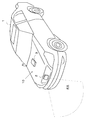
- FIG. 1 is a perspective view schematically showing an entire vehicle. It is a block diagram which shows the vehicle control system in FIG. It is a figure which shows the FM-CW signal and beat signal in the object detection process based on FM-CW system. It is a flowchart which shows the detail of an object detection process. It is a flowchart which shows the detail of the stationary object peak map production
- the vehicle 1 includes a radar device 2 that is a vehicle control system of the present embodiment, and a vehicle control unit 3.
- the radar device 2 is provided at a front portion in front of the vehicle.
- the radar device 2 scans the range of the scanning range RE, calculates the relative distance and relative speed between the vehicle 1 and the object, and calculates the angle of the object viewed from the vehicle 1.
- the mounting position of the radar device 2 is not limited to the front portion in front of the vehicle, but may be the rear or side of the vehicle 1.
- the vehicle control unit 3 controls a device included in the vehicle 1 based on the object data output from the radar device 2. Examples of control by the vehicle control unit 3 include brake control, accelerator control, and alarm device for controlling the devices such as the brake 40 and the throttle 41 described in FIG. There is a warning display when there is a collision risk by controlling 42 and brake control performed by controlling the brake 40. In addition, the occupant is fixed to the seat by a seat belt at the time of collision, and control is performed to reduce damage to the occupant's body by fixing the headrest.
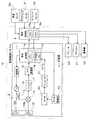
- FIG. 2 is a block diagram of the vehicle control system.
- the vehicle control system 10 is configured by electrically connecting the radar device 2 and the vehicle control unit 3.
- the vehicle control unit 3 of the vehicle control system 10 is electrically connected to various sensors provided in the vehicle 1 such as a vehicle speed sensor 30, a steering sensor 31, and a yaw rate sensor 32. Further, the vehicle control unit 3 is electrically connected to various devices provided in the vehicle 1 such as a brake 40, a throttle 41, and an alarm device 42.
- the radar apparatus 2 includes a signal processing unit 11 (signal processing apparatus of the present invention), a modulation unit 12, a VCO (Voltage Controlled Oscillation) 13, a directional coupler 14, a planar antenna 15, a mixer 16, a filter 17, and an A / D ( Analog / Digital) conversion unit 18, motor drive unit 19, motor 20, and encoder 21.
- the planar antenna 15 includes a transmission antenna 15a and a reception antenna 15b.
- the antenna scanning method of the radar apparatus 2 is described as a mechanical scanning method for driving the antenna in a predetermined direction.
- DBF Digital Beam
- the present invention can also be applied to an electronic scanning method employing a method such as (Forming).
- the modulation unit 12 In the vehicle control by the radar device 2, the modulation unit 12 generates a modulation signal in a predetermined frequency band based on a signal from the signal processing unit 11. This modulated signal is converted into a transmission signal by the VCO 13 and output as a transmission wave via the directional coupler 14 from the transmission antenna 15a (the transmission means of the present invention).
- the transmission wave output from the planar antenna 15 is reflected by an object and received as a reflected wave by the receiving antenna 15b (the receiving means of the present invention).
- the received reflected wave and oscillation signal are mixed by the mixer 16 via the directional coupler 14.
- the reception signal mixed with the transmission signal is a beat signal including information on the relative distance and relative speed from the object, is filtered by the filter 17, and is the relative distance and relative speed from the vehicle 1 equipped with the radar device 2 to the object.
- the beat signal in the band including the information is detected.
- the beat signal filtered to a predetermined frequency band by the filter 17 is converted from an analog signal to a digital signal by the A / D converter 18 and then input to the signal processor 11.
- the radar device 2 scans the planar antenna 15 in a predetermined angle range.
- the angle of the planar antenna 15 is such that when the radar device 2 is provided in a bumper portion in front of the vehicle 1 and the preceding vehicle is located in front of the vehicle 1, the antenna surface of the planar antenna 15 is perpendicular to the traveling direction of the vehicle 1.
- the case where it is in the state is set to 0 degree.
- the planar antenna 15 scans 15 degrees to the left and right from the 0 degree state.
- the scanning of the planar antenna 15 is performed by using the motor driving unit 19 and the motor 20, and the information about the number of passages and the passing direction of a slit (not shown) of the encoder 21 accompanying the scanning of the planar antenna 15 is output to the signal processing unit 11.
- the signal processing unit 11 controls the respective units of the radar device 2 and transmits / receives data to / from the vehicle control unit 3.
- the CPU 11 a performs information processing, and a memory 11 b in which programs used for the processing of the CPU 11 a are stored. And are provided. Various functions of the CPU 11a are realized by executing this program.
- the signal processing unit 11 detects the relative distance and relative speed of the object from the vehicle 1 based on the signal output from the A / D conversion unit 18 (object detection processing). Further, the angle of the object from the vehicle 1 is detected from information output from the encoder 21.
- the reflection point of the object detected by the radar device 2 based on the transmission signal and the reception signal is referred to as a detection point.
- the signal processing unit 11 performs continuity determination between the current detection point and the past detection point, which are detection points detected in the latest object detection processing (determination means of the present invention).
- the signal processing unit 11 adds the counter value related to the past detection point where the continuity with the current detection point can be confirmed by the continuity determination (adding means of the present invention).
- the current detection point that is equal to or greater than the data output threshold (second threshold of the present invention) for outputting object data provided in advance by adding the counter value is output from the signal processing unit 11 to the vehicle control unit 3. Configured as a component of object data.
- the signal processing unit 11 performs a process of subtracting the counter value related to the past detection point where continuity with the current detection point cannot be confirmed (subtraction means of the present invention).
- the counter value is a value that is added or subtracted by a counter 101a, which will be described later, and indicates the presence of a detection point.
- the object data is output from the signal processing unit 11 to the vehicle control unit 3 as being present (output means of the present invention).
- the signal processing unit 11 deletes the data of the target past detection point from the memory 11b (deletion unit of the present invention).
- the signal processing unit 11 specifies a specific detection point that is a detection point that may have been detected by incorrect pairing of a combination of peak signals (specification means of the present invention).
- the counter value to be subtracted from past detection points for which continuity with the current detection point cannot be confirmed is the detection value (hereinafter referred to as “general detection point”) detected by pairing that the combination of peak signals is correct.
- the specific detection point, and the counter value to be subtracted can be changed. Thereby, the timing of deletion from the memory 11b can be adjusted according to whether the past detection point is a specific detection point or another past detection point (general detection point).
- past detection points whose continuity with the current detection point cannot be confirmed whether or not a past detection point that has never exceeded the data output threshold (below the data output threshold) has fallen below the data deletion threshold. Regardless, if it is not detected in the latest object detection process after the past object detection process, it is deleted from the memory 11b. In this way, since there is a high possibility that a past detection point that has exceeded the data output threshold even once, the past detection point data of the target is stored in the memory when it has not been detected even after multiple object detection processes. Deleted from 11b. Since there is a low possibility of the presence of a past detection point that is below the data output threshold, the data of the target past detection point is deleted from the memory 11b unless it is detected by the latest object detection process.
- the detection point has a relative distance, a relative speed, and an angle as parameter values
- the object data has a parameter value of the relative distance, relative speed, and angle of the configured detection point.
- the counter 101a is provided inside the CPU 11a, and the signal processing unit 11 can confirm the continuity between the current detection point and the past detection point, which are detection points detected in the latest object detection process in the continuity determination process.
- the counter value of the past detection point is added.
- the counter 101a is provided inside the CPU 11a.
- the counter 101a may be provided at other positions (for example, inside the signal processing unit 11 or inside the radar device 2).
- the memory 11b of the signal processing unit 11 includes data indicating past detection points (information on the relative distance, relative speed, and angle (lateral position) between the vehicle 1 and an object configured using the detection point information).
- a counter value for a past detection point is stored (storage means of the present invention).
- the memory 11b stores data of a plurality of detection points and counter values of the detection points, and the data and counter values of the detection points are updated according to the result of the continuity determination.
- the vehicle control unit 3 electrically connected to the signal processing unit 11 includes a CPU 3a and a memory 3b.
- the CPU 3a controls each unit of the vehicle 1 and transmits / receives data to / from the signal processing unit 11, Perform information processing.
- the memory 3b stores a program used for the processing of the CPU 3a, and further stores object data transmitted from the signal processing unit 11. Various functions of the CPU 3a are realized by executing this program.
- the brake 40, the throttle 41, and the alarm device 42 are electrically connected to the vehicle control unit 3, and the operation of the vehicle 1 is controlled by controlling these according to the object data.
- the alarm device 42 issues an alarm when the distance between the vehicle 1 and the object is approaching, and notifies the driver who is a user of the abnormality.
- the brake 40 is actuated to reduce the speed of the vehicle 1 or the throttle 41 is throttled to reduce the engine speed.
- a vehicle speed sensor 30 that detects the speed of the vehicle 1
- a steering sensor 31 that detects the steering angle of the steering wheel
- a yaw rate sensor 32 that detects the turning speed of the vehicle 1 are connected to the vehicle control unit 3.
- the steering sensor 31 and the yaw rate sensor 32 it is possible to detect the turning direction of the vehicle 1 and the turning speed of the vehicle 1 according to the steering operation. Therefore, although it is preferable to provide both sensors, it is possible to detect the turning direction of the vehicle 1 with either the steering sensor 31 or the yaw rate sensor 32.
- the transmission wave and reception wave transmitted / received by the planar antenna 15 are signals such as radio waves, lasers, and ultrasonic waves, transmitted from the planar antenna 15, bounced off the object, and received as reflected waves. Any device that can detect object data may be used.
- the antenna is the planar antenna 15 in this embodiment, a lens antenna or a reflecting mirror other than the planar antenna 15 can be used as long as the antenna can output a transmission wave and receive a reflected wave from an object of the transmission wave.
- An antenna or the like may be used.
- the transmitting antenna 15a and the receiving antenna 15b are described as separate configurations, a transmission / reception antenna that can perform both transmission and reception with one antenna may be used.
- FM-CW signal processing An FM-CW (Frequency Modulated Continuous Wave) method will be described as an example of signal processing used in object detection processing.
- the FM-CW method is described as an example.
- the present invention is not limited to this method as long as the object data is calculated by combining a plurality of sections such as an up section and a down section.
- f b beat frequency
- fs frequency
- f r distance frequency
- f up distance frequency in up section
- f dn distance frequency in down section
- f d velocity frequency
- f o center frequency of transmission wave
- ⁇ f frequency deviation width
- f m repetition frequency of the modulated wave
- C speed of light (radio wave velocity)
- T round-trip time of radio wave to the object
- R distance to the object
- V relative velocity with the object
- S Horizontal position.
- the transmission signal indicated by a solid line has a property that the frequency changes at a predetermined cycle, and includes an up section in which the frequency increases and a down section in which the frequency increases to a predetermined frequency and then decreases to a predetermined frequency. Then, the transmission signal repeats a certain change so as to rise to a predetermined frequency after falling to a predetermined frequency.
- the transmission signal is received after being reflected by the object, and becomes a reception signal as indicated by a broken line in FIG.
- the received signal has an up period and a down period as in the case of the transmitted signal.
- An example of the frequency band used in this embodiment is a frequency in the 76 GHz band.
- the beat frequency is calculated based on Equation 1 with time on the horizontal axis and beat frequency on the vertical axis.
- the frequency spectrum is detected by subjecting the beat signal shown in Equation 1 to FFT processing described later.
- a frequency spectrum exceeding a predetermined threshold is detected as a peak signal from the detected frequency spectrum, and a relative distance between the vehicle 1 and an object, a relative speed, and Calculate the angle.
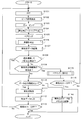
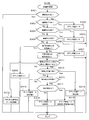
- FIG. 4 shows details of the object detection process.
- the beat signal generated by mixing the transmission signal and the reception signal is A / D converted by the A / D conversion unit 18 and taken into the signal processing unit 11.
- the signal processing unit 11 converts the beat signal into an FFT (Fast Fourier). Transform (fast Fourier transform) processing is performed (step S101).
- the beat signal subjected to FFT processing is detected as a frequency spectrum.
- a frequency spectrum exceeding a threshold provided at a predetermined power level is extracted as a peak signal (step S102).
- the peak signals extracted for each antenna angle are grouped as a group based on the vehicle 1 speed, peak signal strength, and peak signal angle information (step). S103).
- a plurality of groups including one or a plurality of peak signals are generated in each of the up section and the down section.
- a reception signal received from a predetermined reflection range of an object is detected as a peak signal for each angle constituting the reflection range, and one group consisting of the peak signal for each angle is regarded as one reflection point.
- a stationary object detection point is configured among the targets to be paired in the processing of step S105 between the peak signals of the plurality of groups generated in the up section and the plurality of groups generated in the down section.
- Peak signal classification processing is performed for classifying the position of the peak signal to be classified into any of a plurality of regions in a map corresponding to the peripheral region of the vehicle 1 (step S104).
- the stationary object detection point is, for example, a stationary object in which, when the vehicle 1 approaches a target object at 40 km / h, the object appears to be approaching at a speed of 40 km / h when viewed from the vehicle 1. This is a detection point that is not accompanied by a change in position over time.
- step S105 After the process of step S104 in FIG. 4, the pairing process of step S105 is performed.
- the peak signals of the plurality of groups generated in the up section and the plurality of groups generated in the down section are grouped into the speed of the vehicle 1, the signal strength of the grouped peak signals, and the grouped signals.
- This is a process of combining based on the signal angle information (step S105).
- detection points having parameters of relative distance from the object, relative speed, and angle are detected.
- step S106 A continuity determination process for deriving whether or not is performed (step S106). The continuity determination process in step S106 will be described in detail with reference to FIGS.
- step S107 the counter value to which the value is added or subtracted is recorded in the memory 11b together with the corresponding detection point data depending on whether or not the detection point is continuously detected.
- step S108 the process proceeds to step S110, and the counter value of the target detection point is the data output threshold value. Whether it is the above or not is derived (step S110).
- step S108 when the detection point is a new detection point detected for the first time (when continuity is zero), or when the detection point is detected for the first time last time and this time is also detected (continuity once). In the case of (No in step S108), it is derived whether or not the detection point is a detection point of a moving object (step S109).
- step S109 Whether or not it is a detection point of a moving object can be determined by the relative speed of the detected detection point with respect to the vehicle 1, and when it is not a detection point of a moving object (in the case of a detection point of a stationary object) (step S109 is No), It is derived whether or not the ACC of the vehicle 1 is in an OFF state (step S116). If the ACC of the vehicle 1 is in an OFF state (step S116 is Yes), the process is terminated. If the ACC of the vehicle 1 is not in the OFF state (No in step S116), the process returns to step S101, and detection points are detected by scanning.
- step S109 if the detection point is the detection point of the moving object (step S109 is Yes), the processing of pairing correctness determination (step S115) is performed.
- the detection point of the moving object is the target of determination as described above.
- the detection point of the moving object is, for example, when the vehicle 1 approaches the target object at 40 km / h among the detection points detected in the process up to step S105, the detection point is as viewed from the vehicle 1. It is a moving object detection point that appears to be approaching at a speed of 70 km / h (the object is traveling toward the vehicle 1 at a speed of 30 km / h). It is a detection point where changes.
- the detection point of the moving object is divided into the detection point of the oncoming vehicle that faces in the direction of the vehicle 1 and the detection point of the preceding vehicle that travels in the same direction as the traveling direction of the vehicle 1.
- the detection point of the oncoming vehicle that is directed toward the vehicle 1 will be described.
- the detection point is limited to the detection point of the oncoming vehicle. It can also be applied to the detection point of the preceding vehicle.
- the number of peak signals constituting the stationary object data classified among the plurality of regions of the map in which the position of the moving object detection point is classified in step S104 is predetermined. If it falls within a region that is greater than or equal to the threshold value, the detection point of the moving object is derived as a specific detection point that is a detection point that may be detected by incorrect pairing of a combination of peak signals. A detailed description of this determination will be described later in detail with reference to FIGS. 11 and 12.
- step S115 it is derived whether or not the vehicle 1 is in the ACC-OFF state (step S116). If the vehicle 1 is in the ACC-OFF state (step S116 is Yes), the process ends. If the ACC of the vehicle 1 is not in the OFF state (No in step S116), the process returns to step S101, and detection points are detected by scanning.
- This detection point combining process is a process of combining one or a plurality of detection points which are one reflection point of one object into one object data. Specifically, a process of combining detection points based on one or a plurality of reflection points from one object of a moving object such as a passenger car, a truck, and a motorcycle, or a stationary object such as a guardrail, an iron bridge, and a guardrail as one object data. is there.
- This object data is output to the vehicle control unit 3 (step S112). Based on the output object data, the vehicle control unit 3 controls the vehicle 1 using each vehicle control unit such as the operation of the brake 40, the operation of the throttle 41, and the operation of the alarm device 42.
- step S113 when the vehicle 1 is in the ACC-OFF state (step S113 is Yes), the process is terminated.
- step S113 is No
- the process returns to step S101 to perform a new object detection process. Repeat.
- step S110 if the counter value of the past detection point is not equal to or greater than the data output threshold (No in step S110), the data of the past detection point whose counter value is less than the data output threshold is deleted from the memory 11b (step S110) S114) The process ends.
- the xy coordinate axes shown in FIG. 6 and subsequent figures are fixed relative to the vehicle 1, and the lateral direction (left-right direction) of the vehicle 1 corresponds to the x-axis direction and the vertical direction (traveling direction) corresponds to the y-axis direction.
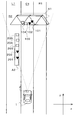
- a stationary object A1 iron bridge
- a stationary object A2 (guardrail) are detected within the scanning range RE of the radar apparatus 2 provided in the vehicle 1 whose traveling direction is the + y direction on the road C1. It is shown that.
- the radar apparatus 2 detects a plurality of detection points 101, 102, 103, and 104 for the stationary object A1 located in the traveling direction (+ y direction) of the vehicle 1 on the road C1. is doing.
- the radar apparatus 2 detects a stationary object A2 on the road L1 in the left direction ( ⁇ x direction) of the vehicle.
- the stationary object A2 has a plurality of detection points 201, 202, and detection points. A point 203, a detection point 204, and a detection point 205 are detected.
- the detection point 101 and the detection point 102 are inherently stationary object detection points, but the pairing is mistaken for the detection point of the moving object (towards the direction of the vehicle 1).
- the detection point of the oncoming vehicle that travels in the following is also detected as “the detection point of the oncoming vehicle”).
- the remaining detection points 103 and 104 of the stationary object A1 are detected as stationary object detection points.
- the detection point 201 and the detection point 202 are detection points for a stationary object, but pairing is erroneously detected as a detection point for an oncoming vehicle.
- the remaining detection points 203, 204, and 205 of the stationary object A2 are detected as stationary object detection points.
- Such a pairing error is likely to occur when a plurality of groups of peak signals are present at close positions.
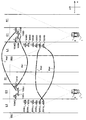
- FIG. 7 is a diagram showing peak signal groups in the up section and the down section.
- the scanning range RE1 represents a peak signal group detected in the up section
- the scanning range RE2 represents a peak signal group detected in the down section.
- the detection point 101 constituting the stationary object A1 should be detected as a stationary object detection point by pairing the peak group 101U and the peak group 101D from the signal intensity and angle information of the peak signal. Since a plurality of peak groups (hereinafter simply referred to as “groups”) exist at close positions, the group 101U and the group 102D are erroneously paired (PA1). It becomes the detection point of the car.
- groups a plurality of peak groups
- the detection point 102 should be detected as a stationary object detection point by pairing the group 102U and the group 102D from the signal intensity and angle information of the peak signal, but the group 102U and the group 101D are detected.
- PA2 paired
- the other group 103U and group 103D and the group 104U and group 104D are properly paired, and if paired, they become detection points for stationary objects.
- the detection point 201 constituting the stationary object A2 should be detected as a stationary object detection point by pairing the group 201U and the group 201D from the signal intensity and angle information of the peak signal. Since they exist in close proximity, the group 201U and the group 202D are erroneously paired (PA3), and if paired, they become detection points for oncoming vehicles.
- PA3 erroneously paired
- the detection point 202 should be detected as a detection point of a stationary object by pairing the group 202U and the group 202D from the signal intensity and angle information of the peak signal, but a plurality of groups exist at close positions. Therefore, the group 202U and the group 201D are erroneously paired (PA4), and if paired, they become detection points for the oncoming vehicle.
- PA4 erroneously paired
- the other group 203U and group 203D, group 204U and group 204D, group 205U and group 205D are to be properly paired and detected. It becomes a point.
- the groups 103U, 104U, 203U, 204U, and 205U are extracted in the up section group, and the groups 103D, 104D, 203D, 204D, and 205D are extracted in the down section group. And are extracted.
- FIG. 8 is an application diagram of the peak signal constituting the stationary object detection point to the map MA.
- the peak signals of the groups 103M, 104M, 203M, 204M, 205M, and 206M shown in FIG. 8 are detected.
- the group 103M is a group extracted based on the group 103U and the group 103D. From the peak signal constituting the group 103U and the peak signal constituting the group 103D, only the peak signal having the peak signal corresponding to the up section and the down section is extracted from the peak signal intensity and angle information. Then, the group 103M is extracted. That is, since the group 103U has three peak signals and the group 103D has three peak signals, the group 103M is extracted as a result of extracting corresponding peak signals based on the signal intensity and angle information of each peak signal. Is a group of three peak signals.
- another group 104M is a group extracted based on the group 104U and the group 104D. From the peak signal constituting the group 104U and the peak signal constituting the group 104D, only peak signals having peak signals corresponding to the up and down sections are extracted from the peak signal intensity and angle information. Thus, the group 104M is configured. That is, the group 104U has three peak signals and the group 104D has four peak signals. As a result of extracting the corresponding peak signals based on the signal intensity and angle information of each peak signal, the group 104M has A group of three peak signals is formed. In this way, the peak signal corresponding to each of the up section and down section groups constituting the detection point of the stationary object is detected. As a result, the other group 203M has four signals, the group 204M has four signals, the group 205M has four signals, and the group 206M has four signals.
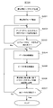
- step S203 it is determined whether or not the detection of the peak signals of all groups has been completed. If the detection of the peak signals of all the groups is completed (Yes at Step S203), the process proceeds to Step S204. If the detection of the peak signals of all the groups is not completed (No at Step S203), the process of Step S202 is repeated. Do. In the present embodiment, detection of peak signals of all groups of data of group 103U and group 103D, group 104U and group 104D, group 203U and group 203D, group 204U and group 204D, group 205U and group 205D. Is completed, and the process proceeds to each process.
- the frequency of the peak signal is calculated using Equation 2 corresponding to the map MA described below (step S204).
- the lateral position of the peak signal is calculated using Equations 3 and 4 (Step S205).
- the lateral position is the distance in the left-right direction of the vehicle 1. The lateral position will be described in detail below.
- the peak signal is classified into the corresponding section of the map MA (step S206). Then, it is determined whether or not all peak signals have been classified into the map MA (step S207). When the classification of all peak signals into the map MA has been completed (step S207 is Yes), the process ends. If the classification of all peak signals into the map has not been completed (No at step S207), the process returns to step S204, and the classification process into the peak signal map is repeated.
- the above-described processing for classifying the peak signal into the map MA will be specifically described with reference to FIG.
- the map MA shown in FIG. 8 corresponds to the peripheral area of the vehicle 1 and is classified into a plurality of areas.
- This map MA is formed in two directions, the vertical axis and the horizontal axis, and the vertical axis (y-axis direction) of the map MA indicates the frequency.
- the vicinity of the position where the radar device 2 of the vehicle 1 is provided is 0 kHz, and the frequency increases as the vehicle 1 moves in the traveling direction (+ y direction), and is divided every 20 kHz.
- the frequency corresponds to the distance in the vertical direction (y-axis direction).
- the horizontal axis (x-axis direction) of the map MA indicates the distance in the horizontal direction, the position of the vehicle 1 is the origin, and the left-right direction (x-axis direction) is the position of the detection point based on the position of the vehicle 1. It is defined as a horizontal position.
- the map MA is classified into a plurality of areas by such vertical and horizontal divisions, and thus it is possible to confirm the correctness of the pairing process of the detection points constituting the moving object data for each area.
- the peak signal constituting the detection point of the stationary object detected in step S203 of FIG. 5 is classified into the corresponding category of the map MA according to the frequency and the lateral position.
- Each peak signal of the group 103 and the group 104 located on the same road C1 as the vehicle 1 corresponds to the frequency section 9 (160 kHz to 180 kHz) on the vertical axis of the map MA from the frequency and the horizontal position, and the horizontal axis represents the vehicle. This corresponds to a section C2 (from -1.8 m to +1.8 m) having a position and width corresponding to one road C1. Therefore, the peak signals of the group 103 and the group 104 correspond to the area MA1 of the map MA, and the total number of peak signals in this area MA1 is 6.
- the peak signal of the group 203, group 204, group 205, and group 206 located on the road L1 in the left direction ( ⁇ x direction) of the vehicle 1 indicates the vertical axis of the map MA from the frequency and lateral position.
- the horizontal axis is the section L2 (-1.8 m to -5.4 m) having the position and width corresponding to the road L1 in the left direction of the vehicle 1 (-x direction) It corresponds to.
- each peak signal of group 203, group 204, group 205, and group 206 corresponds to area MA2 of map MA, and the total number of peak signals in this area MA2 is 16.
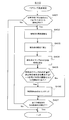
- step S106 the continuity determination process in step S106 shown in FIG. 4 will be described in detail with reference to FIG. In this process, the continuity between the current detection point detected by the most recent object detection process and the past detection point detected in the past is determined, and the counter value is added to the detection point having continuity. If there is no detection point, the counter value is subtracted.
- step S301 If the continuity between the current detection point detected by the object detection process and the past detection point is zero (step S301 is Yes), that is, if the detection point is detected for the first time in the latest object detection process, the process ends.
- the counter value is not added to or subtracted from the past detection points by the counter 101a.
- the data of the detection point and the counter value (in this case, the counter value 0) are recorded in the memory 11b in the process of step S107 shown in FIG. Thereafter, in each process of FIG. 9, the data of the detection point and the counter value are recorded in the memory 11b as the counter value increases or decreases.
- step S301 If the continuity of the detection points is not zero (No in step S301) and the continuity between the current detection point and the past detection point is one (Yes in step S302), the counter 101a determines the past detection point. The value of 5 is added to the counter value (step S303), and the process ends.
- step S304 When the detection continuity of the detection point is not once (No in step S302), it is derived whether or not the detection continuity of the current detection point and the past detection point is two times (step S304). When the detection point detection continuity is twice (Yes in step S304), the counter 101a adds 5 to the counter value of the detection point (step S305), and the process is terminated.
- the position where the counter value is 10 is defined as a data output threshold value A1 (hereinafter also referred to as “threshold value A1”), and the value of the current detection point is obtained by adding the value to the counter of the past detection points.
- threshold value A1 a data output threshold value
- the signal processing unit 11 outputs the object data composed of the detection points of the threshold value A1 to the vehicle control unit 3.
- step S306 When the continuity of detection of the current detection point and the past detection point is not twice (No in step S304), it is derived whether the continuity of detection of the detection point is three times (step S306). When the continuity is three times (step S306 is Yes), the counter 101a adds 2 to the counter value of the past detection point (step S307), and the process is terminated.
- step S308 it is derived whether or not the previously detected detection point is detected in the current scan.
- a value of 2 is added to the counter value of the past detection point (step S309).
- a predetermined upper limit is provided for the value obtained by adding the counter value to the past detection point. For example, when the counter value exceeds 14, the counter value does not increase any more.
- step S308 If the detection point detected in the previous scan is not detected in the current scan (No in step S308), that is, if there is no current detection point that is continuous with the past detection point, past detection in which continuity cannot be confirmed The point is read from the memory 11b (step S310), and the counter value is subtracted according to the type of the detection point such as whether the detection point is for a stationary object or a moving object.
- extrapolation processing refers to a case where a detection point exists at a predetermined position when the continuity of the past detection point whose past detection point counter value has reached the threshold value A1 or more cannot be confirmed. Is updated, and the counter value is subtracted. The updated detection point (current detection point) data and the subtracted counter value are recorded in the memory 11b.
- the extrapolation process at the past detection point whose counter value is equal to or greater than the threshold value A1 is performed immediately from the memory 11b according to the counter value subtracted when the number of processing times is one.
- a data deletion threshold value B1 hereinafter also referred to as “threshold value B1”
- the counter value of the past detection point is lower than the threshold value A1 by subtraction of the counter value accompanying a plurality of extrapolation processes.
- step S311 If the detection point is not a detection point whose counter value has reached the threshold value A1 or more in step S311 (No in step S311), the target past data is deleted from the memory 11b (step S312), and the process ends. . Thereby, the past detection points with a low possibility of existence can be deleted from the memory 11b at an early stage, and other past detection points with a high possibility of existence can be preferentially recorded.
- step S311 performs a process of subtracting the counter value according to the type of each detection point.
- the detection point read from the memory 11b is a detection point of a stationary object (Yes in step S313)
- the counter value of the target past detection point is subtracted by 2 (step S314), and the process ends.
- step S315 it is determined whether the detection point is an oncoming vehicle (step S315). Whether or not the detection point is an oncoming vehicle is determined by comparing with past detection point data to determine whether or not the vehicle is approaching the vehicle 1. If the detection point is an oncoming vehicle (Yes in step S315), if the detection point is a specific detection point that may be mispaired (Yes in step S317), normal detection in which pairing has been performed normally The counter value that is a subtraction value larger than the subtraction value of the point is subtracted by 3 (step S318), and the process is terminated.
- step S317 If the detection point of the oncoming vehicle is a general detection point that is not a specific detection point (No in step S317), the counter value having a smaller subtraction value than that of the specific detection point is subtracted by 2 (step S319), and the process ends. .
- step S316 If the detection point is not an oncoming vehicle (No in step S315), that is, if the detection point is a preceding vehicle, the counter value is subtracted by 2 (step S316) and the process is terminated.
- addition and subtraction values of these counter values and the values of the threshold value A1 and the threshold value B1 are examples, and may be changed to other values.
- the subtraction value of the counter value at the specific detection point may be other values.
- the value is larger than the subtraction value of the detection point, and the value of the threshold A1 is larger than the value of the threshold B1.
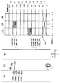
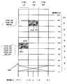
- FIG. 10 is a diagram showing the transition of the counter value at the detection point in the above continuity determination process.
- the vertical axis represents the counter value, and the upper limit value is 14.
- one scale corresponds to a time corresponding to one cycle of the object detection process. In this embodiment, one cycle is 150 ms.
- the detection point R1 is detected by the object detection process, and the signal processing unit 11 performs a process of recording the data of the detection point R1 and the counter value 0 of the detection point R1 in the memory 11b.
- the next T2 object detection process when the detection point R1 detected in the latest 150 ms (one cycle before) object detection process is set as a past detection point, a continuous current detection point R2 is detected. . By detecting the current detection point R2, the counter value of the past detection point R1 is incremented by 5, and the data and counter value of the detection point R2 are updated from 0 to 5 and recorded in the memory 11b.
- the signal processing unit 11 deletes the data and the counter value of the past detection point R2 in the memory 11b from the memory 11b, and records the data and the counter value 0 of the newly detected detection point S1.
- the signal processing unit 11 adds 5 to the counter value 0 of the past detection point S1, and records the data of the current detection point S2 and the counter value 5 in the memory 11b.
- the current detection point S3 having continuity is detected when the detection point S2 is a past detection point. Therefore, the signal processing unit 11 adds a value of 5 to the counter value 5 of the past detection point S2, and records the data of the current detection point S3 and the counter value 10 in the memory 11b. In addition, since the counter value of the current detection point S3 is equal to or greater than the threshold A1 for outputting the object data configured using the detection point information to the vehicle control unit 3, the current detection point S3 is an element constituting the object data. And output to the vehicle control unit 3.
- the current detection point is S4 at T6, and the counter value 12 obtained by adding 2 to the data of the detection point S4 and the counter value 10 is stored in the memory. 11b.
- the detection point S5 becomes the current detection point with respect to the past detection point S4, and the counter value 14 obtained by adding 2 to the data of the detection point S5 and the counter value 12 is recorded in the memory 11b.
- the counter value of the detection point S5 is the upper limit counter value 14, in the object detection process of T8, which is the next object detection process, even if the current detection point S6 having the past detection point as S5 is continuous, the counter value Is recorded as 14 in the memory 11b.
- the detection points having continuity from the detection points S1 to S6 described so far are specific detection points that may have been detected by incorrect pairing of the peak signals.
- the transition of each detection point will be described below with the detection points after SA7 as the detection points after SB7 where the combination of peak signals may be paired with the correct combination.
- the current detection point SB7 is virtually derived.
- the counter value of the current detection point SB7 virtually derived by extrapolation processing is subtracted by 2 from the original counter value, and the memory 11b has a counter obtained by subtracting 2 from the data of the current detection point SB7 and the counter value 14.
- the value 12 is recorded.
- the counter value of the detection point is subtracted by 2 for each extrapolation process, and together with the data of the detection point The counter value is recorded in the memory 11b.
- the data of the detection point SB11 with the past detection point at T13 as SB10 and the counter value 4 are recorded in the memory 11b.
- the detection point SB11 is below the data deletion threshold B1, which is a threshold for deleting detection point data from the memory 11b. For this reason, the data of SB11 whose recording has been updated in the memory 11b from T1 to T13 is deleted from the memory 11b.
- the current detection point SA7 virtually derived from the specific detection point S6 as a past detection point is the data of the detection point SA7.
- the counter value 11 obtained by subtracting the value of 3 from the counter value 14 of the specific detection point S6 is recorded in the memory 11b.
- the data of the virtual current detection point SA8 and the counter value 8 at T10 with the specific detection point SA7 as the past detection point are recorded in the memory 11b.
- the data of the virtual current detection point SA9 of T11 with the specific detection point SA8 as the past detection point and the counter value 5 are recorded in the memory 11b.
- the detection point SA9 recorded in the memory 11b is below the data deletion threshold B1
- the data at the detection point SA9 is deleted from the memory 11b by the scan of T11.
- the peak signal combination may have been detected by incorrect pairing because the subtraction value when extrapolating a specific detection point is larger than the subtraction value when extrapolating a general detection point.
- the specific detection point is deleted from the memory 11b at T11
- the general detection point is deleted from the memory 11b at T13. That is, the specific detection point is deleted from the memory 11b by 300 ms (two cycles of the object detection process earlier than the general detection point).
- the specific detection point when S6 that exceeds the threshold A1 at least once is set as the specific detection point, when the continuity of the specific detection point S6 cannot be confirmed, the specific detection point from the memory 11b until the data of the specific detection point falls below the threshold B1. Extrapolation is performed without deleting the data. That is, the number of subtractions until the counter value of the specific detection point falls below the threshold value B1 is multiple times (in FIG. 10, the counter value 12 of SA7 is obtained by subtracting 3 from the counter value 14 of S6, and 3 is subtracted from the counter value 12 of SA7. The counter value is subtracted so that the counter value 8 of SA8 and the counter value 5 of SA9 obtained by subtracting 3 from the counter value 8 of SA8 are subtracted, and the specific detection point of the counter value below the threshold B1 Is deleted.
- the specific detection point is equal to or greater than the threshold value A1 and is output to the vehicle control unit 3, the specific detection is immediately detected from the memory 11b even if the combination of the peak signals may be detected by incorrect pairing.
- the combination of peak signals is an error through a plurality of processes without deleting point data, it is possible to determine the correctness of pairing of specific detection points.
- step S115 of FIG. 4 is a flowchart of the pairing correctness determination process.
- step S108 If the detection points detected by the pairing process in step S105 of FIG. 4 are not detected three or more times in succession (step S108 is No) and this is a detection point of a moving object (step S109 is Yes), this A pairing correctness determination process is executed, and it is determined whether or not it is a detection point of an oncoming vehicle approaching in the direction of the vehicle 1 at a predetermined speed or higher (for example, 10 km / h or higher) (step S301).
- a predetermined speed or higher for example, 10 km / h or higher
- step S401 If there is an oncoming vehicle detection point approaching the vehicle 1 at a predetermined speed or higher (Yes in step S401), the process proceeds to step S402. If there is no detection point of an oncoming vehicle approaching the vehicle 1 at a predetermined speed or higher (No in step S401), the process ends.
- step S401 the frequency of the detection point of the oncoming vehicle is calculated (step S402). Then, the lateral position of the detection point of the oncoming vehicle is calculated (step S403). The calculation of the frequency is performed using the above “Formula 2”, and the calculation of the lateral position is performed using the above “Formula 3” and “Formula 4”.
- step S404 the corresponding area of the oncoming vehicle detection point map MA is calculated using the detection point frequency and lateral position data calculated in step S402 and step S403 (step S404).
- step S405 determines as a specific detection point and turns on the flag (step S406).
- the detection point of the oncoming vehicle determined as the specific detection point is a detection point that is highly likely to be mistaken for the target of the pairing process, and that the specific detection point is that each vehicle control unit of the vehicle control unit 3 This is one of the determination conditions for control.
- the correctness of the pairing process can be confirmed at an early stage by performing pairing correct / incorrect determination on the newly detected detection point and the detection point detected for the first time last time and also detected this time.
- step S405 the position of the oncoming vehicle detection point map MA corresponds to an area in which the peak signal constituting the classified stationary object detection point in the plurality of areas of the map is equal to or greater than a predetermined threshold. If not (No in step S405), or after a specific detection point is counted up (step 406), it is determined whether or not the corresponding areas of the detection points of all oncoming vehicles have been classified (step 406). S407).
- step S407 If the corresponding areas of the detection points of all oncoming vehicles have been classified (step S407 is Yes), the process ends. If the corresponding areas of the detection points of all oncoming vehicles have not been classified (No in step S407), the process returns to step S402.
- the map MA is a map in which peak signals constituting stationary object detection points are classified, and is grouped into a region MA1 of a frequency section 9 and a lateral section C2. A total of six peak signals of 103M and 104M are classified, and a total of sixteen peak signals of group 203M, group 204M, group 205M, and group 206M are classified into an area M2 of frequency section 5 and horizontal position section L2. Yes.
- the horizontal position section is C2, and the threshold value of the peak signal is set to four in this section C2.
- the horizontal position section is L2, and the threshold value of the peak signal is set to 15 in this section L2.
- the threshold value of the peak signal is set to 15 for the section R2 in the horizontal position.
- the threshold value set for each section in the left-right direction is greater than that of the vehicle 1 than the respective regions of C2, which are regions that coincide with the vehicle 1 in the left-right direction among the plurality of regions of the map MA.
- the different region L2 or R2 is set higher.
- the threshold of the peak signal that constitutes the detection point of a stationary object is set low in the area of the own lane where the probability of the presence of a stationary object is low, and the existence probability of the stationary object is not self Considering that the existence probability of an oncoming vehicle that travels toward the vehicle 1 is higher than the lane, the threshold value of the peak signal constituting the stationary object detection point is set high.
- the peak signals constituting the detection points of the stationary object are classified, and the threshold values are set in the respective areas, and based on the information on the frequency and the lateral position of the detection point of the moving object, It classifies into each area of detection point map MA.
- the detection point 101 and detection point 102 detected as detection points of the oncoming vehicle are classified into the area MA1
- the detection point 201 and detection point 202 also detected as detection points of the oncoming vehicle are classified into the area MA2.
- the threshold value of the peak signal in the area MA1 is 4, the number of peak signals constituting the stationary object detection point in the area MA1 is 6, so the detection point 101 of the oncoming vehicle classified in the area MA1.
- Each of the detection points 102 of the oncoming vehicle is incremented by a specific detection point counter.
- the threshold value of the peak signal in the area MA2 is 15
- the number of peak signals constituting the stationary object detection point in the area MA2 is 16, so the detection point 201 of the oncoming vehicle classified into the area MA2
- Each of the detection points 202 of the oncoming vehicle is incremented by a counter of specific detection points.
- the detection point which comprises a moving object in both the area
- the threshold value of the area different from the own vehicle is higher than the threshold value of the area of the own vehicle, pairing of the detection points of the oncoming vehicle is incorrect in an area different from the own vehicle where the oncoming vehicle is likely to exist. There is no possibility of targeting. Furthermore, since there is a high possibility that a detection point for a stationary object such as a guardrail exists in a different area from the host vehicle, if a detection point for a stationary object exists even if the threshold is set high, the detection point for a stationary object The number of peak signals constituting the number exceeds the threshold value.
- the peak signal constituting the stationary object detection points located in the sections L2 and R2 is the section C2. Since it is easy to get in or to be affected by noise, the vicinity area from the vehicle 1 constituted by these sections is not used in the processing of this embodiment.
Landscapes
- Engineering & Computer Science (AREA)
- Radar, Positioning & Navigation (AREA)
- Remote Sensing (AREA)
- Physics & Mathematics (AREA)
- Computer Networks & Wireless Communication (AREA)
- General Physics & Mathematics (AREA)
- Electromagnetism (AREA)
- Signal Processing (AREA)
- Radar Systems Or Details Thereof (AREA)
Abstract
Description
(1):所定周期で周波数が変わる送信信号と、該送信信号に基づく送信波の物体での反射波を受信した受信信号との差分周波数を示すピーク信号を前記送信信号の周波数が上昇する第1期間と周波数が下降する第2期間の各々について取得し、前記第1期間で取得された前記ピーク信号および前記第2期間で取得された前記ピーク信号をペアリングすることで前記ピーク信号に係る物体の反射点である検知点を検出する物体検出処理を行なう信号処理装置であって、
過去の前記物体検出処理において検出された前記検知点である過去検知点を示すデータと、前記過去検知点についての存在の可能性を示すカウンタ値とを記憶する記憶手段と、
前記過去検知点が、直近の前記物体検出処理において検出された前記検知点である現在検知点との連続性を有しているかの判定を行なう判定手段と、
前記判定手段により前記現在検知点との連続性を有していないと判定された前記過去検知点に係る前記カウンタ値を減算する減算手段と、
前記カウンタ値が第1の閾値を下回った場合に、該カウンタ値に係る前記過去検知点を示すデータを前記記憶手段から削除する削除手段と、
前記第1期間で取得された前記ピーク信号と前記第2期間で取得された前記ピーク信号を誤ってペアリングして検出された可能性のある前記検知点を特定検知点として特定する特定手段とを備え、
前記減算手段は、前記過去検知点に係る前記カウンタ値から第1の値を減算し、前記特定検知点に係る前記カウンタ値から前記第1の値と異なる第2の値を減算することを特徴とするもの。
前記判定手段により前記現在検知点との連続性を有すると判定された前記過去検知点に係る前記カウンタ値を加算する加算手段と、
前記加算手段により加算された前記カウンタ値が前記第1の閾値よりも値の大きい第2の閾値以上の場合に、当該カウンタ値に係る前記検知点の情報を含むと共に車両が備える装置を制御するために用いられる物体データを出力する出力手段とをさらに備え、
前記減算手段は、前記カウンタ値が前記第2の閾値以上となった前記特定検知点が前記現在検知点との連続性を有していないと前記判定手段により判定された場合に、前記特定検知点に係る前記カウンタ値が前記第1の閾値を下回るまで複数回にわたって当該カウンタ値を減算することを特徴とするもの。
過去の前記物体検出処理において検出された前記検知点である過去検知点を示すデータと、前記過去検知点についての存在の可能性を示すカウンタ値とを記憶手段に記憶し、
前記過去検知点が、直近の前記物体検出処理において検出された前記検知点である現在検知点との連続性を有しているかの判定を行ない、
前記判定により前記現在検知点との連続性を有していないと判定された前記過去検知点に係る前記カウンタ値を減算し、
前記カウンタ値が第1の閾値を下回った場合に、該カウンタ値に係る前記過去検知点を示すデータを前記記憶手段から削除し、
前記第1期間で取得された前記ピーク信号と前記第2期間で取得された前記ピーク信号を誤ってペアリングして検出された可能性のある前記検知点を特定検知点として特定し、
前記過去検知点に係る前記カウンタ値からは第1の値が減算され、前記特定検知点に係る前記カウンタ値からは前記第1の値と異なる第2の値が減算されることを特徴とするもの。
<1-1.車両全体図>
図1に示されるように、車両1には本実施形態の車両制御システムであるレーダ装置2と、車両制御部3とが備えられている。レーダ装置2は車両前方のフロント部分に設けられている。レーダ装置2は走査範囲REの範囲を走査して、車両1と物体との相対距離、および相対速度を算出するとともに、車両1からみた物体の角度を算出する。なお、レーダ装置2の搭載位置は車両前方のフロント部分に限らず、車両1の後方や側方でもよい。
図2は車両制御システムのブロック図である。車両制御システム10は、レーダ装置2と車両制御部3とが電気的に接続して構成されている。また、車両制御システム10の車両制御部3は、車速センサ30、ステアリングセンサ31、およびヨーレートセンサ32などの車両1に設けられる各種センサと電気的に接続されている。さらに、車両制御部3はブレーキ40、スロットル41、および警報器42などの車両1に設けられる各種装置と電気的に接続されている。
<2-1.FM-CWの信号処理>
次に、物体検出処理において用いられる信号処理の一例としてFM-CW(Frequency Modulated Continuous Wave)の方式について説明する。なお、本実施形態では、FM-CWの方式を例に説明を行なうが、アップ区間とダウン区間のような複数の区間を組み合わせて物体データを算出する方式であれば、この方式に限定されない。

図4に物体検出処理の詳細を示す。先ず、送信信号と受信信号とをミキシングすることにより生じるビート信号をA/D変換部18によりA/D変換して、信号処理部11に取り込み、信号処理部11によりビート信号にFFT(Fast Fourier Transform:高速フーリエ変換)処理を施す(ステップS101)。
次に、図4のステップS104の静止物ピークマップ生成の処理について図5から図8を用いて詳細に説明する。先ず検出される物体について、図6を参照しつつ検知点検出の具体例を示す。



<2-4.連続性判定処理>
次に、図4に示したステップS106の連続性判定処理について、図9を用いて詳細に説明する。この処理においては、直近の物体検出処理により検出された現在検知点と過去に検出された過去検知点との連続性を判定し、連続性がある検知点はカウンタ値を加算し、連続性のない検知点はカウンタ値を減算する。
次に、図4のステップS115に示すペアリング正誤判定処理について、図11および図12を用いて詳細に説明する。図11はペアリング正誤判定処理のフローチャートである。
Claims (6)
- 所定周期で周波数が変わる送信信号と、該送信信号に基づく送信波の物体での反射波を受信した受信信号との差分周波数を示すピーク信号を前記送信信号の周波数が上昇する第1期間と周波数が下降する第2期間の各々について取得し、前記第1期間で取得された前記ピーク信号および前記第2期間で取得された前記ピーク信号をペアリングすることで前記ピーク信号に係る物体の反射点である検知点を検出する物体検出処理を行なう信号処理装置であって、
過去の前記物体検出処理において検出された前記検知点である過去検知点を示すデータと、前記過去検知点についての存在の可能性を示すカウンタ値とを記憶する記憶手段と、
前記過去検知点が、直近の前記物体検出処理において検出された前記検知点である現在検知点との連続性を有しているかの判定を行なう判定手段と、
前記判定手段により前記現在検知点との連続性を有していないと判定された前記過去検知点に係る前記カウンタ値を減算する減算手段と、
前記カウンタ値が第1の閾値を下回った場合に、該カウンタ値に係る前記過去検知点を示すデータを前記記憶手段から削除する削除手段と、
前記第1期間で取得された前記ピーク信号と前記第2期間で取得された前記ピーク信号を誤ってペアリングして検出された可能性のある前記検知点を特定検知点として特定する特定手段とを備え、
前記減算手段は、前記過去検知点に係る前記カウンタ値から第1の値を減算し、前記特定検知点に係る前記カウンタ値から前記第1の値と異なる第2の値を減算する
ことを特徴とする信号処理装置。 - 請求項1に記載の信号処理装置において、
前記第2の値は、前記第1の値よりも大きい値とする
ことを特徴とする信号処理装置。 - 請求項1または2に記載の信号処理装置において、
前記判定手段により前記現在検知点との連続性を有すると判定された前記過去検知点に係る前記カウンタ値を加算する加算手段と、
前記加算手段により加算された前記カウンタ値が前記第1の閾値よりも値の大きい第2の閾値以上の場合に、当該カウンタ値に係る前記検知点の情報を含むと共に車両が備える装置を制御するために用いられる物体データを出力する出力手段とをさらに備え、
前記減算手段は、前記カウンタ値が前記第2の閾値以上となった前記特定検知点が前記現在検知点との連続性を有していないと前記判定手段により判定された場合に、前記特定検知点に係る前記カウンタ値が前記第1の閾値を下回るまで複数回にわたって当該カウンタ値を減算することを特徴とする信号処理装置。 - 請求項1乃至3のいずれか1項に記載の信号処理装置と、
前記送信波を出力する送信手段と、
前記反射波を受信する受信手段と、
を備えることを特徴とするレーダ装置。 - 車両に搭載される請求項4に記載のレーダ装置と、
前記車両が備える装置を制御する車両制御装置と、
を備えることを特徴とする車両制御システム。 - 所定周期で周波数が変わる送信信号と、該送信信号に基づく送信波の物体での反射波を受信した受信信号との差分周波数を示すピーク信号を前記送信信号の周波数が上昇する第1期間と周波数が下降する第2期間の各々について取得し、前記第1期間で取得された前記ピーク信号および前記第2期間で取得された前記ピーク信号をペアリングすることで前記ピーク信号に係る物体の反射点である検知点を検出する物体検出処理を行なう信号処理方法であって、
過去の前記物体検出処理において検出された前記検知点である過去検知点を示すデータと、前記過去検知点についての存在の可能性を示すカウンタ値とを記憶手段に記憶し、
前記過去検知点が、直近の前記物体検出処理において検出された前記検知点である現在検知点との連続性を有しているかの判定を行ない、
前記判定により前記現在検知点との連続性を有していないと判定された前記過去検知点に係る前記カウンタ値を減算し、
前記カウンタ値が第1の閾値を下回った場合に、該カウンタ値に係る前記過去検知点を示すデータを前記記憶手段から削除し、
前記第1期間で取得された前記ピーク信号と前記第2期間で取得された前記ピーク信号を誤ってペアリングして検出された可能性のある前記検知点を特定検知点として特定し、
前記過去検知点に係る前記カウンタ値からは第1の値が減算され、前記特定検知点に係る前記カウンタ値からは前記第1の値と異なる第2の値が減算される
ことを特徴とする信号処理方法。
Priority Applications (2)
| Application Number | Priority Date | Filing Date | Title |
|---|---|---|---|
| DE112011102221.2T DE112011102221B4 (de) | 2010-06-30 | 2011-06-23 | Signalverarbeitungsvorrichtung, Radarvorrichtung, Fahrzeugsteuerungssystem und Signalverarbeitungsverfahren |
| US13/807,092 US9261589B2 (en) | 2010-06-30 | 2011-06-23 | Signal processing device, radar device, vehicle control system, and signal processing method |
Applications Claiming Priority (2)
| Application Number | Priority Date | Filing Date | Title |
|---|---|---|---|
| JP2010148806A JP5576727B2 (ja) | 2010-06-30 | 2010-06-30 | 信号処理装置、レーダ装置、車両制御システム、および、信号処理方法 |
| JP2010-148806 | 2010-06-30 |
Publications (1)
| Publication Number | Publication Date |
|---|---|
| WO2012002251A1 true WO2012002251A1 (ja) | 2012-01-05 |
Family
ID=45401969
Family Applications (1)
| Application Number | Title | Priority Date | Filing Date |
|---|---|---|---|
| PCT/JP2011/064411 Ceased WO2012002251A1 (ja) | 2010-06-30 | 2011-06-23 | 信号処理装置、レーダ装置、車両制御システム、および信号処理方法 |
Country Status (4)
| Country | Link |
|---|---|
| US (1) | US9261589B2 (ja) |
| JP (1) | JP5576727B2 (ja) |
| DE (1) | DE112011102221B4 (ja) |
| WO (1) | WO2012002251A1 (ja) |
Cited By (1)
| Publication number | Priority date | Publication date | Assignee | Title |
|---|---|---|---|---|
| CN103852762A (zh) * | 2012-11-28 | 2014-06-11 | 富士通天株式会社 | 雷达设备和信号处理方法 |
Families Citing this family (18)
| Publication number | Priority date | Publication date | Assignee | Title |
|---|---|---|---|---|
| JP5739701B2 (ja) * | 2011-03-23 | 2015-06-24 | 富士通テン株式会社 | レーダ装置用の演算装置、レーダ装置、レーダ装置用の演算方法およびプログラム |
| JP5977972B2 (ja) * | 2012-03-19 | 2016-08-24 | 富士通テン株式会社 | レーダ装置 |
| JP6200644B2 (ja) * | 2012-12-07 | 2017-09-20 | 富士通テン株式会社 | レーダ装置、及び、信号処理方法 |
| EP2952926B1 (en) * | 2013-02-01 | 2018-01-31 | Mitsubishi Electric Corporation | Radar system |
| US9297892B2 (en) * | 2013-04-02 | 2016-03-29 | Delphi Technologies, Inc. | Method of operating a radar system to reduce nuisance alerts caused by false stationary targets |
| JP6348332B2 (ja) * | 2014-04-25 | 2018-06-27 | 株式会社デンソーテン | レーダ装置、車両制御システム及び信号処理方法 |
| JP6534808B2 (ja) * | 2014-11-28 | 2019-06-26 | 株式会社デンソーテン | レーダ装置、および、信号処理方法 |
| CN105445714B (zh) * | 2015-11-24 | 2018-08-31 | 大连楼兰科技股份有限公司 | 汽车前向防撞系统信号处理方法 |
| EP3211445B1 (en) | 2016-02-29 | 2019-06-12 | Nxp B.V. | Radar system |
| EP3211444B1 (en) * | 2016-02-29 | 2019-06-12 | Nxp B.V. | Radar system |
| US10768298B2 (en) | 2016-06-14 | 2020-09-08 | Magna Electronics Inc. | Vehicle sensing system with 360 degree near range sensing |
| JP6815840B2 (ja) * | 2016-11-16 | 2021-01-20 | 株式会社デンソーテン | レーダ装置および物標検知方法 |
| JP6828603B2 (ja) * | 2017-06-09 | 2021-02-10 | トヨタ自動車株式会社 | 物標検出装置 |
| JP6828602B2 (ja) * | 2017-06-09 | 2021-02-10 | トヨタ自動車株式会社 | 物標検出装置 |
| US10627828B2 (en) * | 2017-06-30 | 2020-04-21 | Casio Computer Co., Ltd. | Autonomous movement device, autonomous movement method and program recording medium |
| JP7103824B2 (ja) * | 2018-03-30 | 2022-07-20 | 株式会社小松製作所 | 作業機械の制御システム、作業機械、及び作業機械の制御方法 |
| US11300967B2 (en) * | 2019-10-25 | 2022-04-12 | Toyota Research Institute, Inc. | System and method for collection of performance data by a vehicle |
| US12007476B2 (en) | 2021-09-13 | 2024-06-11 | Magna Electronics Inc. | Method for detecting objects via a vehicular sensing system |
Citations (3)
| Publication number | Priority date | Publication date | Assignee | Title |
|---|---|---|---|---|
| JP2004017763A (ja) * | 2002-06-14 | 2004-01-22 | Denso Corp | 車両制御装置,プログラム |
| JP2008051614A (ja) * | 2006-08-24 | 2008-03-06 | Honda Motor Co Ltd | 物体検知装置 |
| JP2010071805A (ja) * | 2008-09-18 | 2010-04-02 | Toyota Motor Corp | レーダ装置 |
Family Cites Families (17)
| Publication number | Priority date | Publication date | Assignee | Title |
|---|---|---|---|---|
| US6011507A (en) * | 1996-11-12 | 2000-01-04 | Raytheon Company | Radar system and method of operating same |
| JP2002236170A (ja) | 2001-02-06 | 2002-08-23 | Fujitsu Ten Ltd | Fm−cwレーダ処理装置 |
| JP3753652B2 (ja) * | 2001-12-04 | 2006-03-08 | 富士通テン株式会社 | Fm−cwレーダのミスペアリング判定及び信号処理方法 |
| JP3753071B2 (ja) * | 2002-01-07 | 2006-03-08 | 株式会社村田製作所 | レーダ |
| JP3801068B2 (ja) * | 2002-02-19 | 2006-07-26 | 株式会社デンソー | Fmcwレーダ装置,プログラム |
| JP3983158B2 (ja) * | 2002-11-25 | 2007-09-26 | 富士通株式会社 | 電波レーダの信号処理方法 |
| JP2004205279A (ja) * | 2002-12-24 | 2004-07-22 | Denso Corp | レーダ装置,プログラム |
| JP3960228B2 (ja) | 2003-01-20 | 2007-08-15 | 株式会社デンソー | レーダ装置,プログラム |
| JP2004053611A (ja) | 2003-08-15 | 2004-02-19 | Fujitsu Ten Ltd | レーダ測距装置 |
| JP4278507B2 (ja) * | 2003-12-26 | 2009-06-17 | 富士通テン株式会社 | Fm−cwレーダ装置 |
| US8446312B2 (en) * | 2007-12-25 | 2013-05-21 | Honda Elesys Co., Ltd. | Electronic scanning type radar device, estimation method of direction of reception wave, and program estimating direction of reception wave |
| JP4843003B2 (ja) * | 2008-08-05 | 2011-12-21 | 富士通テン株式会社 | 信号処理装置、レーダ装置、及び信号処理方法 |
| JP2010148806A (ja) | 2008-12-26 | 2010-07-08 | Panasonic Corp | 炊飯器 |
| JP2010175256A (ja) | 2009-01-27 | 2010-08-12 | Honda Motor Co Ltd | 物体検知装置 |
| JP4837755B2 (ja) * | 2009-02-24 | 2011-12-14 | 本田技研工業株式会社 | 物体検知装置 |
| DE102010037163B4 (de) * | 2009-08-27 | 2017-12-21 | Fujitsu Ten Ltd. | Signalverarbeitungsvorrichtung, Radarvorrichtung, Fahrzeugsteuersystem, Signalverarbeitungsverfahren und computerlesbares Medium |
| JP5596368B2 (ja) * | 2010-02-23 | 2014-09-24 | 富士通テン株式会社 | レーダ装置、物体検知システム、および、物体検知方法 |
-
2010
- 2010-06-30 JP JP2010148806A patent/JP5576727B2/ja not_active Expired - Fee Related
-
2011
- 2011-06-23 WO PCT/JP2011/064411 patent/WO2012002251A1/ja not_active Ceased
- 2011-06-23 DE DE112011102221.2T patent/DE112011102221B4/de not_active Expired - Fee Related
- 2011-06-23 US US13/807,092 patent/US9261589B2/en not_active Expired - Fee Related
Patent Citations (3)
| Publication number | Priority date | Publication date | Assignee | Title |
|---|---|---|---|---|
| JP2004017763A (ja) * | 2002-06-14 | 2004-01-22 | Denso Corp | 車両制御装置,プログラム |
| JP2008051614A (ja) * | 2006-08-24 | 2008-03-06 | Honda Motor Co Ltd | 物体検知装置 |
| JP2010071805A (ja) * | 2008-09-18 | 2010-04-02 | Toyota Motor Corp | レーダ装置 |
Cited By (1)
| Publication number | Priority date | Publication date | Assignee | Title |
|---|---|---|---|---|
| CN103852762A (zh) * | 2012-11-28 | 2014-06-11 | 富士通天株式会社 | 雷达设备和信号处理方法 |
Also Published As
| Publication number | Publication date |
|---|---|
| JP5576727B2 (ja) | 2014-08-20 |
| US20130093613A1 (en) | 2013-04-18 |
| DE112011102221T5 (de) | 2013-04-04 |
| US9261589B2 (en) | 2016-02-16 |
| JP2012013484A (ja) | 2012-01-19 |
| DE112011102221B4 (de) | 2017-07-13 |
Similar Documents
| Publication | Publication Date | Title |
|---|---|---|
| JP5576727B2 (ja) | 信号処理装置、レーダ装置、車両制御システム、および、信号処理方法 | |
| US8633849B2 (en) | Radar device, object detection system, and object detection method | |
| JP4007498B2 (ja) | 車載用レーダ装置 | |
| JP6077226B2 (ja) | レーダ装置、および、信号処理方法 | |
| CN102472816B (zh) | 雷达装置 | |
| US8810445B2 (en) | Method and apparatus for recognizing presence of objects | |
| KR100961932B1 (ko) | 차량 안전주행 레이더 매핑 시스템 | |
| JP6092596B2 (ja) | レーダ装置、および、信号処理方法 | |
| US8638254B2 (en) | Signal processing device, radar device, vehicle control system, signal processing method, and computer-readable medium | |
| EP1094336A2 (en) | Object recognition apparatus | |
| JP2011069710A (ja) | 信号処理装置、レーダ装置、物体検出システム、信号処理方法、および、プログラム | |
| JP2015141109A (ja) | レーダ装置、及び、信号処理方法 | |
| US9383440B2 (en) | Radar apparatus and signal processing method | |
| JP5424959B2 (ja) | 信号処理装置、レーダ装置、車両制御システム、および、信号処理方法 | |
| JP2019066240A (ja) | レーダ装置及び情報処理方法 | |
| US7557907B2 (en) | Object-detection device for vehicle | |
| EP3540467B1 (en) | Range finding system, range finding method, in-vehicle device, and vehicle | |
| JP3761888B2 (ja) | 車載レーダ装置 | |
| JP4079739B2 (ja) | 車載用レーダ装置 | |
| TWI448715B (zh) | 移動參數估計方法、角度估計方法及判斷方法 | |
| JP2008064743A (ja) | 車載レーダ装置 | |
| JP2009058316A (ja) | レーダ装置、物体検出方法、及び車両 | |
| US12411235B2 (en) | Object detection device, object detection method, and computer-readable storage medium | |
| JP2015210156A (ja) | レーダ装置、車両制御システム、および、信号処理方法 | |
| JP6555132B2 (ja) | 移動物体検出装置 |
Legal Events
| Date | Code | Title | Description |
|---|---|---|---|
| 121 | Ep: the epo has been informed by wipo that ep was designated in this application |
Ref document number: 11800716 Country of ref document: EP Kind code of ref document: A1 |
|
| WWE | Wipo information: entry into national phase |
Ref document number: 13807092 Country of ref document: US |
|
| WWE | Wipo information: entry into national phase |
Ref document number: 1120111022212 Country of ref document: DE Ref document number: 112011102221 Country of ref document: DE |
|
| 122 | Ep: pct application non-entry in european phase |
Ref document number: 11800716 Country of ref document: EP Kind code of ref document: A1 |