WO2012002148A1 - 表示装置 - Google Patents
表示装置 Download PDFInfo
- Publication number
- WO2012002148A1 WO2012002148A1 PCT/JP2011/063667 JP2011063667W WO2012002148A1 WO 2012002148 A1 WO2012002148 A1 WO 2012002148A1 JP 2011063667 W JP2011063667 W JP 2011063667W WO 2012002148 A1 WO2012002148 A1 WO 2012002148A1
- Authority
- WO
- WIPO (PCT)
- Prior art keywords
- image
- screen
- display unit
- imaging substrate
- main surface
- Prior art date
- Legal status (The legal status is an assumption and is not a legal conclusion. Google has not performed a legal analysis and makes no representation as to the accuracy of the status listed.)
- Ceased
Links
Images









Classifications
-
- G—PHYSICS
- G03—PHOTOGRAPHY; CINEMATOGRAPHY; ANALOGOUS TECHNIQUES USING WAVES OTHER THAN OPTICAL WAVES; ELECTROGRAPHY; HOLOGRAPHY
- G03B—APPARATUS OR ARRANGEMENTS FOR TAKING PHOTOGRAPHS OR FOR PROJECTING OR VIEWING THEM; APPARATUS OR ARRANGEMENTS EMPLOYING ANALOGOUS TECHNIQUES USING WAVES OTHER THAN OPTICAL WAVES; ACCESSORIES THEREFOR
- G03B21/00—Projectors or projection-type viewers; Accessories therefor
- G03B21/14—Details
- G03B21/28—Reflectors in projection beam
-
- G—PHYSICS
- G02—OPTICS
- G02B—OPTICAL ELEMENTS, SYSTEMS OR APPARATUS
- G02B30/00—Optical systems or apparatus for producing three-dimensional [3D] effects, e.g. stereoscopic images
- G02B30/20—Optical systems or apparatus for producing three-dimensional [3D] effects, e.g. stereoscopic images by providing first and second parallax images to an observer's left and right eyes
- G02B30/34—Stereoscopes providing a stereoscopic pair of separated images corresponding to parallactically displaced views of the same object, e.g. three-dimensional [3D] slide viewers
- G02B30/35—Stereoscopes providing a stereoscopic pair of separated images corresponding to parallactically displaced views of the same object, e.g. three-dimensional [3D] slide viewers using reflective optical elements in the optical path between the images and the observer
-
- H—ELECTRICITY
- H04—ELECTRIC COMMUNICATION TECHNIQUE
- H04N—PICTORIAL COMMUNICATION, e.g. TELEVISION
- H04N13/00—Stereoscopic video systems; Multi-view video systems; Details thereof
- H04N13/30—Image reproducers
- H04N13/302—Image reproducers for viewing without the aid of special glasses, i.e. using autostereoscopic displays
-
- H—ELECTRICITY
- H04—ELECTRIC COMMUNICATION TECHNIQUE
- H04N—PICTORIAL COMMUNICATION, e.g. TELEVISION
- H04N13/00—Stereoscopic video systems; Multi-view video systems; Details thereof
- H04N13/30—Image reproducers
- H04N13/356—Image reproducers having separate monoscopic and stereoscopic modes
- H04N13/359—Switching between monoscopic and stereoscopic modes
-
- H—ELECTRICITY
- H04—ELECTRIC COMMUNICATION TECHNIQUE
- H04N—PICTORIAL COMMUNICATION, e.g. TELEVISION
- H04N13/00—Stereoscopic video systems; Multi-view video systems; Details thereof
- H04N13/30—Image reproducers
- H04N13/324—Colour aspects
Definitions
- the present invention relates to a display device, and more particularly to a display device capable of displaying an aerial image.
- Patent Document 1 Japanese Patent Application Laid-Open No. 2008-158114
- Patent Document 1 includes a reflective surface-symmetric imaging element that forms an image of light from a projection object at a plane-symmetric position.
- the reflective surface-symmetric imaging element is formed in a plate shape, and a plurality of holes are formed in the reflective surface-symmetric imaging element. When the hole is viewed from above the hole, the hole is formed in a rectangular shape. A mirror surface is formed on each inner side surface of the hole, and the adjacent mirror surfaces are arranged so as to cross each other vertically.
- the light from the projection enters the hole from one opening of the hole.
- the light that has entered the hole is repeatedly reflected in the hole, and is emitted to the outside from the other opening of the hole.
- the reflected light radiated from the other hole and the incident light entering the hole are observed from above the reflective surface-symmetric imaging element, the reflected light travels in the opposite direction to the incident light.
- the incident angle of the incident light is equal to the reflection angle of the reflected light.
- the light from the projection object forms an image at a position that is plane-symmetrical with the reflection-type plane-symmetric imaging element as a reference plane.
- Patent Document 2 The optical element described in International Publication No. 2007/116669 (Patent Document 2) is formed in a plate shape, and the reflection-type plane-symmetric connection described in Japanese Patent Laid-Open No. 2008-158114 (Patent Document 1). A configuration similar to that of the image element is employed. For this reason, this optical element forms an image of light from the projection object entering from one surface of the element surface at a position that is plane-symmetrical with the optical element as a reference plane. As a result, a real image is displayed in a space having no physical entity on the other side of the element surface.
- Patent Document 2 describes a three-dimensional aerial image display device provided with this optical element.
- This three-dimensional aerial image display apparatus includes a substrate that functions as a reflective image forming element and a display unit that is disposed on the lower side of the substrate. The light from the display unit that has entered the substrate from the lower surface of the substrate is imaged above the upper surface of the substrate.
- a three-dimensional aerial image display apparatus described in Japanese Patent Application Laid-Open No. 2009-229905 includes a two-sided corner reflector array and a display including a display surface for displaying an image.
- the two-surface corner reflector array connects a real image of a projection object at a plane-symmetric position with respect to a geometric plane serving as a symmetry plane.
- the three-dimensional aerial image display device includes a drive unit that moves the two-surface corner reflector array in the vertical direction.
- Patent Document 4 A product scanning type three-dimensional aerial image display described in Japanese Patent Application Laid-Open No. 2009-75483 (Patent Document 4) includes a two-sided corner reflector array, a display including a display surface for displaying an image, and the display with respect to the display surface. And a drive unit that moves in the vertical direction.
- JP 2008-158114 A International Publication No. 2007/116663 JP 2009-229905 A JP 2009-75483 A
- the observer sees the mirror surface of the two-sided corner reflector array located on the display from an oblique direction, and a part of the image is covered with the mirror surface of the two-sided corner reflector array, and the image is excellent. Can not be observed.
- the line of sight coincides with the height direction of the mirror surface, so that a part of the image is covered by the mirror surface. Can be suppressed.
- the observer observes the image from an oblique direction and cannot see the image satisfactorily.
- the present invention has been made in view of the above-described problems, and an object thereof is to provide a display device that can display an aerial image and can also observe a flat image well. It is to be.
- the display device includes a display unit having a screen capable of displaying an image and an imaging substrate formed in a plate shape.
- the imaging substrate reflects the light from the first main surface and the second main surface arranged in the thickness direction, and the display unit entering from the first main surface side toward the second main surface side, and the second main surface. And a plurality of mirror surfaces to be imaged on the main surface side.
- the mirror surface portion extends in the thickness direction of the imaging substrate.
- the display unit and the imaging substrate are arranged so that the screen is inclined with respect to the first main surface, and light from the screen enters the imaging substrate from the first main surface side and forms an image on the second main surface side. It is possible to switch between the first state and the second state in which the display unit and the imaging substrate are arranged in the thickness direction and arranged along each other.
- a plurality of hole portions extending in the thickness direction are formed in the imaging substrate, and the mirror surface portion is formed on the inner peripheral surface of the hole portion.
- the screen In the second state, the screen can be viewed through the hole.
- the display unit includes a black matrix having a light shielding property.
- the black matrix includes a plurality of linear portions provided at intervals.
- the imaging substrate extends in the first direction along the first main surface, and extends in the second direction with a plurality of first beam portions arranged at intervals in a second direction intersecting the first direction. And a plurality of second beam portions arranged at intervals in the first direction.
- a plurality of holes surrounded by the first beam portion and the second beam portion are formed in the imaging substrate.
- the mirror surface portion is formed on the inner peripheral surface of the hole portion.
- the display device supports at least one of the display unit and the imaging substrate so as to be rotatable around the first virtual axis so that an angle formed by the screen and the first main surface is variable.
- a control unit that controls a position for displaying an image, and a detection unit that detects an angle formed by the screen and the first main surface. The control unit moves the image away from the first virtual axis as the angle between the screen and the first main surface decreases.
- the screen in the first state is a first reference screen
- an image displayed on the first reference screen is a reference image
- a virtual axis passing through the reference image and the imaging substrate is a second virtual axis.
- the screen when the display unit is moved so that the angle formed between the screen and the first main surface from the first state is small is set as the second reference screen, and the intersection of the second reference screen and the second virtual axis is an image. Display position.
- the control unit moves the image to the image display position.
- control unit increases the brightness of the screen as the angle between the screen and the first main surface decreases.
- the screen in the first state is a first reference screen
- an image displayed on the first reference screen is a reference image
- a virtual axis passing through the reference image and the imaging substrate is a second virtual axis.
- the said control part adjusts the brightness
- the screen in the first state is a first reference screen
- an image displayed on the first reference screen is a reference image
- a virtual axis passing through the reference image and perpendicular to the first reference screen is a second virtual axis.
- the intersection point between the imaging substrate and the second imaginary axis is defined as a reference intersection point
- the screen when the display unit is moved from the first state so that the angle between the screen and the first main surface is reduced is referred to as a second reference screen.
- a virtual axis passing through the reference intersection and perpendicularly intersecting the second reference screen is defined as a third virtual axis.
- the control unit moves the image to the intersection of the third virtual axis and the second reference screen.
- an angle at which light from the display unit enters the first main surface is an incident angle.
- the imaging component ratio of the imaging substrate becomes smaller as the incident angle becomes smaller than the predetermined incident angle.
- the control unit increases the luminance of the image when the angle formed between the screen and the first main surface is smaller than the predetermined incident angle.
- the imaging substrate is provided so as to be retractable from above the display unit.
- the display unit includes a first display unit and a second display unit. At least one of the first display unit and the second display unit can be switched between the second state and the first state.
- the display unit is located on the second main surface of the imaging substrate in the second state.
- an aerial image can be displayed, and an observer can observe a flat image well.
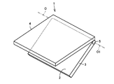
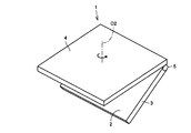
- FIG. 1 is a perspective view illustrating a schematic configuration of a display device 1 according to a first embodiment.
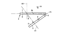
- 3 is a side view illustrating a schematic configuration of the display device 1.
- FIG. It is a side view which shows the state which rotated the display part 3 so that intersection angle (theta) may become small from the state shown in FIG.
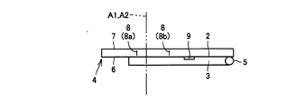
- It is a side view which shows the state which rotated the display part 3 from the state shown in FIG. 2 is a perspective view showing an imaging substrate 4.
- FIG. 4 is a perspective view showing a part of an imaging substrate 4.
- FIG. It is a perspective view which shows one mirror surface part 8.
- 3 is a cross-sectional view schematically showing a display unit 3.
- FIG. 3 is a plan view schematically showing a part of a color filter 26.
- FIG. 3 is a plan view schematically showing a part of an imaging substrate 4.
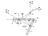
- FIG. FIG. 4 is a plan view of the imaging substrate 4 and the display unit 3 as viewed from above the imaging substrate 4 in a state where the display unit 3 and the imaging substrate 4 are bonded together. is there. It is a schematic diagram when an image is displayed in the state shown in FIG. It is a schematic diagram which shows a mode when the image 9 is seen in the gaze direction 33 from the viewpoint 32 shown in FIG. It is a schematic diagram which shows a mode when the image 9 is observed in the gaze direction 35 from the viewpoint 34.
- FIG. It is a perspective view which shows typically the display apparatus 1 which concerns on this Embodiment 2.
- FIG. 17 is a schematic diagram schematically showing the imaging substrate 4 and the screen 2 when the imaging substrate 4 and the screen 2 are viewed from above the imaging substrate 4 in the state of FIG. 16. It is a perspective view which shows the state which rotated the display part 3 so that the display part 3 and the image formation board
- FIG. 10 is a side view showing an imaging position when the crossing angle ⁇ is sequentially changed in the display device 1 according to the third embodiment. It is a graph which shows typically the relation between the radiation angle of light, and the brightness in one pixel.
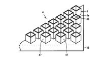
- FIG. 6 is a side view for explaining a display device 1 according to a fourth embodiment. It is a perspective view which shows the modification of the imaging substrate.
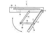
- FIG. 10 is a side view schematically showing a first modification of display device 1. It is a side view which shows typically the 2nd modification of the display apparatus 1.
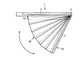
- FIG. 11 is a side view showing a third modification of display device 1.
- FIG. 10 is a plan view showing a fourth modification of display device 1. It is a top view which shows the modification of the display apparatus 1 shown in FIG. It is a side view which shows typically the 5th modification of the display apparatus 1.
- FIG. 10 is a side view for explaining a display device 1 according to a fourth embodiment. It is a perspective view which shows the modification of the imaging substrate.
- FIG. 10 is a side view schematically showing a first modification of display device 1. It is a side view which shows typically the 2nd modification of the display apparatus 1.
- FIG. 11 is a side view showing a third modification of display device 1.
- FIG. 10 is
- FIG. 32 is a side view showing a modification of display device 1 shown in FIG. 31.
- 11 is a schematic diagram showing a seventh modification of display device 1.
- FIG. FIG. 34 is a schematic diagram showing a modification of the display device 1 shown in FIG. 33.
- FIG. 34 is a schematic diagram showing a modification of the display device 1 shown in FIG. 33. It is a side view which shows typically the 8th modification of the display apparatus.
- FIG. 1 is a perspective view illustrating a schematic configuration of the display device 1 according to the first embodiment
- FIG. 2 is a side view illustrating a schematic configuration of the display device 1.
- the display device 1 includes a display unit 3 having a screen 2 capable of displaying an image, an imaging substrate 4, and a hinge unit 5.
- the imaging substrate 4 and the display unit 3 are supported by the hinge unit 5 so that at least one of the imaging substrate 4 and the display unit 3 can rotate around the rotation center line (virtual axis) O1 with respect to the other.
- the hinge unit 5 is provided on one side of the outer periphery of the display unit 3, and the display unit 3 is supported by the hinge unit 5 so as to be rotatable about the rotation center line O1. ing.
- the screen 2 of the display unit 3 is arranged to be inclined with respect to the imaging substrate 4.
- the imaging substrate 4 is formed in a flat plate shape, and includes a main surface 6 and a main surface 7 arranged in the thickness direction of the imaging substrate 4, and a plurality of mirror surface portions 8.
- the imaging substrate 4 is formed with a plurality of holes extending in the thickness direction of the imaging substrate 4 and reaching from the main surface 6 to the main surface 7.
- the mirror surface portion 8 is formed on the inner peripheral surface of the hole. Is formed.
- the mirror surface portion 8 extends in the thickness direction of the imaging substrate 4, and the height direction of the mirror surface portion 8 coincides with the thickness direction of the imaging substrate 4.
- the hole portions and the mirror surface portion 8 are evenly distributed on the imaging substrate 4.
- the main surface 6 is provided so as to face the screen 2 of the display unit 3, and light from the image 9 displayed on the screen 2 enters the imaging substrate 4 from the opening of the hole.
- a virtual axis perpendicular to the screen 2 is a virtual axis A1
- a virtual axis extending in the thickness direction of the imaging substrate 4 is a virtual axis A2.
- the smaller one is defined as the intersection angle ⁇ . Note that the crossing angle ⁇ changes as the display unit 3 rotates about the rotation center line O1, and corresponds to the opening angle of the imaging substrate 4 and the display unit 3.
- the light from the image 9 enters the imaging substrate 4 from the main surface 6 and is reflected toward the main surface 7 side by the mirror surface portion 8.
- the reflected light forms an image above the main surface 7 and an aerial image 10 is displayed.
- the aerial image 10 is a plane of the image 9 with the virtual plane P1 as a reference plane.
- An image is formed at a symmetrical position.
- the light R1 traveling in the direction perpendicular to the screen 2 out of the light from the image 9 is reflected by the mirror surface portion 8A, and the arbitrary light R0 radiated from the image 9 is mirrored. Reflected by the portion 8B. It can be seen that the reflected light of the light R1 and the reflected light of the light R0 intersect at the portion where the aerial image 10 is located and form an image at the focal position.
- the aerial image 10 is located above the main surface 7.
- the distance between the aerial video 10 and the virtual plane P1 is equal to the distance between the image 9 and the virtual plane P1.
- the opening angle between the imaging substrate 4 and the display unit 3 is increased.
- the distance between the image 9 and the virtual plane P1 is increased, and the aerial video 10 can be floated higher.
- the height at which the displayed aerial image 10 is lifted can be adjusted by adjusting the intersection angle ⁇ .
- FIG. 3 is a side view showing a state in which the display unit 3 is rotated so that the intersection angle ⁇ is smaller than the state shown in FIG. As shown in FIG. 3, when the crossing angle ⁇ is reduced, the distance between the image 9 and the virtual plane P1 is shortened, and the floating height of the aerial image 10 is also lowered.
- FIG. 4 shows a state in which the display unit 3 is rotated so that the crossing angle ⁇ becomes small and the crossing angle ⁇ becomes 0 degree.
- the display unit 3 is located on the lower surface side of the main surface 6 of the imaging substrate 4, the display unit 3 and the imaging substrate 4 are arranged in the thickness direction of the imaging substrate 4, They are arranged along each other.
- the screen 2 of the display unit 3 and the main surface 6 of the imaging substrate 4 are arranged along each other, and the height direction of the mirror surface part 8A and the mirror surface part 8B and the virtual axis A1 perpendicular to the screen 2 are provided.
- Parallel As shown in FIG. 4, when the observer views the image 9 from above the imaging substrate 4 when the crossing angle ⁇ is 0 degree, the observer's line of sight is parallel to the height direction of the mirror surface portion 8. Become.
- the crossing angle ⁇ is 0 degree
- the mirror surface portion 8 can be prevented from covering the image 9, and the observer is good.
- the image 9 can be observed.
- FIG. 5 is a perspective view showing the imaging substrate 4.
- the imaging substrate 4 has a plurality of holes 11 formed therein.
- the holes 11 are arranged in an array.
- the imaging substrate 4 includes a beam portion 12 extending in the first direction D1, a beam portion 13 extending in the second direction D2, and a frame portion 14 disposed on the outer peripheral edge of the imaging substrate 4.
- a plurality of beam portions 12 are arranged at intervals in the second direction D2, and a plurality of beam portions 13 are also arranged at intervals in the first direction D1. Both end portions of the beam portions 12 and 13 are connected to the frame portion 14.
- the first direction D1 extends along the main surface of the imaging substrate 4, and the second direction D2 extends along the main surface of the imaging substrate 4 and is orthogonal to the first direction D1.
- Each hole 11 is formed by two adjacent beam portions 12 and two adjacent beam portions 13.
- the hole 11 passes through the imaging substrate 4 and extends in the thickness direction of the imaging substrate 4.
- the mirror surface portion 8 is formed on the inner peripheral surface of the hole portion 11.
- FIG. 6 is a perspective view showing a part of the imaging substrate 4. As shown in FIG. 6, the beam portion 12 or the beam portion 13 is located between the adjacent mirror surface portions 8. An opening 16 of the hole 11 is formed in the main surface 6 of the imaging substrate 4, and an opening 17 is formed in the main surface 7.
- FIG. 7 is a perspective view showing one mirror surface portion 8. As shown in FIG. 7, the mirror surface portion 8 includes four reflecting surfaces 8a to 8d. The reflective surface 8a and the reflective surface 8c are provided with a space therebetween, and are disposed so as to face each other. The reflecting surface 8c and the reflecting surface 8d are provided with a space therebetween and are disposed so as to face each other.
- the reflecting surface 8b is arranged so as to connect one side of the reflecting surface 8a and one side of the reflecting surface 8c
- the reflecting surface 8d is arranged so as to connect the other side of the reflecting surface 8a and the other side of the reflecting surface 8c.
- the reflecting surface 8a intersects the reflecting surface 8b and the reflecting surface 8d perpendicularly
- the reflecting surface 8c also intersects the reflecting surface 8b and the reflecting surface 8d perpendicularly.
- the reflecting surfaces 8a and 8c both extend in the second direction D2, and the reflecting surfaces 8b and 8d extend in the first direction D1.
- the reflection surfaces 8 a to 8 d are formed so as to reach the opening 16 from the opening 17, and the reflection surfaces 8 a to 8 d extend in the thickness direction of the imaging substrate 4.
- mirror surface portions 8 are formed in 5 cm ⁇ 5 cm of the imaging substrate 4.
- each of the reflecting surfaces 8a to 8d located at the opening edge of the hole 11 is, for example, 50 to 1000 ⁇ m, and preferably 150 ⁇ m.
- the height of the reflecting surfaces 8a to 8d is, for example, 50 ⁇ m to 1000 ⁇ m, and preferably 150 ⁇ m.
- the light R0 includes incident light IR1 and IR2
- the light R1 includes incident light IR3 and IR4.
- the incident light IR1 enters the hole 11 from the opening 16 shown in FIG. 6 and is reflected by the reflecting surface 8a. This reflected light is reflected again by the reflecting surface 8b.
- the reflected light RL1 reflected by the reflecting surface 8b is radiated to the outside from the opening 17 shown in FIG.
- the incident light IR2 is reflected by the reflecting surface 8b, and this reflected light is reflected again by the reflecting surface 8a. And it is radiated
- the reflected light RL1 and the incident light IR1 are viewed in plan from above the imaging substrate 4, the reflected light RL1 and the incident light IR1 are parallel, and the traveling direction of the reflected light RL1 and the traveling direction of the incident light IR1 are It is the opposite. Similarly, the reflected light RL2 and the incident light IR2 are parallel to each other and their traveling directions are opposite to each other.
- the mirror surface part 8 reflects without changing the vertical component of the light R0. For this reason, as shown in FIG. 8, a part of the reflected light of the light R ⁇ b> 0 passes through the focal region FA located above the light source 15 in a state where the imaging substrate 4 is viewed in plan.
- the mirror surface portion 8 reflects the incident light IR3 of the light R1 as the reflected light RL3, and reflects the incident light IR4 as the reflected light RL4.
- the reflected light RL3 is parallel to the incident light IR3, and the traveling direction of the reflected light RL3 is exactly opposite to the traveling direction of the incident light IR3.
- the reflected light RL4 is also parallel to the incident light IR4, and the traveling direction of the reflected light RL4 is exactly opposite to the traveling direction of the incident light IR4. For this reason, the reflected light of the light R1 also passes through the focal area FA.
- the light from the light source 15 incident on the imaging substrate 4 is re-reflected by the imaging substrate 4 and forms an image in the focal region FA.
- the aerial image 10 is formed at a predetermined position.
- the size of the focal area FA is caused by the size of the mirror surface portion 8, and the size of the focal area FA can be reduced by making the mirror surface portion 8 finer.
- the aperture ratio area ratio through which light can pass
- the brightness of the aerial image decreases.
- the resolution of the aerial image decreases. Therefore, the size of the mirror surface portion 8 is appropriately set according to the light collection distance.
- FIG. 9 is a cross-sectional view schematically showing the display unit 3.
- the display unit 3 includes a backlight unit 20 and a display unit 21 disposed on the upper surface of the backlight unit 20.
- the backlight unit 20 emits light toward the display unit 21.
- the display unit 21 includes an active matrix substrate 22 disposed on the upper surface of the backlight unit 20, a counter substrate 23 disposed at a distance from the active matrix substrate 22, and disposed so as to face the active matrix substrate 22. And a liquid crystal layer 24 sealed between the counter substrate 23 and the active matrix substrate 22.
- a polarizing plate (not shown) is arranged between the active matrix substrate 22 and the backlight unit 20, and a polarizing plate (not shown) is also arranged on the upper surface of the counter substrate 23. .
- the vibration directions of light transmitted through each polarizing plate are formed so as to be orthogonal to each other.
- the counter substrate 23 includes a glass substrate 25, a color filter 26 formed on the lower surface of the glass substrate 25, and a counter electrode 27 disposed on the lower surface of the color filter 26.
- the color filter 26 includes a black matrix 28 and a color layer 29.
- the black matrix 28 is formed in a lattice shape, and a plurality of windows are formed in the black matrix 28.
- the color layer 29 is formed in this window portion.
- the active matrix substrate 22 is connected to a plurality of TFT transistors (not shown), a gate wiring connected to the gate electrode of the TFT transistor, a source wiring connected to the source electrode of the TFT transistor, and a drain electrode of the TFT transistor. Pixel electrodes. Gate wirings and source wirings are arranged below the black matrix 28 formed in a lattice shape.
- the light from the backlight unit 20 passes through a polarizing plate (not shown), so that the vibration direction of the light is aligned. Thereafter, the vibration direction of light changes depending on the alignment state of the liquid crystal. As a result, the light that has passed through the liquid crystal layer 24 can pass through the polarizing plate located on the counter substrate 23 or is blocked by the polarizing plate.
- the color filter 26 is provided on the counter substrate 23 side, but may be provided on the active matrix substrate 22.
- FIG. 10 is a plan view schematically showing a part of the color filter 26.
- the color filter 26 includes a black matrix 28 and a color layer 29.
- the black matrix 28 extends in the first direction D1 and is provided with a plurality of beams 30 spaced apart in the second direction D2, and a plurality of the black matrix 28 extends in the second direction D2 and spaced apart in the first direction D1.
- a beam portion 31 is provided.
- a window portion is formed by two adjacent beam portions 30 and two adjacent beam portions 31.
- a color layer 29 is formed in each window portion.
- the color layer 29 includes a red color layer 29r, a green color layer 29g, and a blue color layer 29b.
- FIG. 10 is a diagram schematically illustrating the widths of the beam portions 30 and 31, the size of the color layer 29, and the like.
- FIG. 11 is a plan view schematically showing a part of the imaging substrate 4. As shown in FIG. 11, the imaging substrate 4 extends in the first direction D1 and a plurality of beam portions 12 provided at intervals in the second direction D2, and extends in the second direction D2, and extends in the first direction. And a plurality of beam portions 13 provided at intervals in D1. A hole 11 is formed by the two adjacent beam portions 12 and the two adjacent beam portions 13.
- FIG. 12 is a plan view of the imaging substrate 4 and the display unit 3 from above the imaging substrate 4 in a state where the display unit 3 and the imaging substrate 4 are bonded together as shown in FIG. FIG.
- the beam portion 30 of the black matrix 28 is positioned below the beam portion 12 of the imaging substrate 4, and the beam of the black matrix 28 is positioned below the beam portion 13 of the imaging substrate 4.
- the part 31 is located.
- the beam portion 30 extends along the beam portion 12, and the beam portion 31 extends along the beam portion 13.
- a color layer 29 is located in the hole 11.
- the beam portions 12 and 13 of the imaging substrate 4 are prevented from being positioned on the color layer 29. Note that it is not necessary for both the beam portion 12 and the beam portion 13 of the imaging substrate 4 to be positioned above the beam portion 30 or the beam portion 31 of the black matrix 28, and the beam portion 12 and the beam portion of the imaging substrate 4.
- One of 13 may be located above the beam part 30 or the beam part 31 of the black matrix 28 and may extend along the beam part 30 or the beam part 31.
- the width of the beam portion 12 and the beam portion 13 of the imaging substrate 4 is, for example, 10 ⁇ m, and the width of the beam portion 30 and the beam portion 31 of the black matrix 28 is, for example, about 10 ⁇ m.
- the width of the beam portions 12 and 13 of the imaging substrate 4 is made smaller than the width of the beam portions 30 and 31 of the black matrix 28.
- FIG. 13 is a schematic diagram when an image is displayed in the state shown in FIG.
- the beam portion 12 and the beam portion 13 are marked in an easy-to-understand manner.
- the beam portion 12 and the beam portion 13 are so thick that they cannot be visually recognized.
- FIG. 4 when the intersection angle ⁇ between the virtual axis A1 and the virtual axis A2 is 0 degrees (when the virtual axis A1 and the virtual axis A2 are parallel), as shown in FIG.
- the unit 8 is disposed so as to rise vertically with respect to the color filter 26. Therefore, when the imaging substrate 4 is viewed in plan from directly above the imaging substrate 4, the reflection surfaces 8a to 8d (side surfaces of the beam portions 12 and 13) are not observed.
- FIG. 4 when the image 9 displayed on the display unit 3 is observed from above the imaging substrate 4 with the imaging substrate 4 and the display unit 3 bonded together, FIG. As shown, the image 9 can be observed well.
- FIG. 14 is a schematic diagram showing a state when the image 9 is viewed in the viewing direction 33 from the viewpoint 32 shown in FIG. 2 is a direction perpendicular to the screen 2, and the viewpoint 32 is located on an extension of the virtual axis A1 passing through the image 9.
- the mirror surface portion 8 extends in the direction of the virtual axis A2, and the line-of-sight direction 33 and the extending direction of the virtual axis A2 intersect each other.
- the observer observes the image 9 through the hole 11 of the inclined mirror surface portion 8.
- the mirror surface portion 8 covers a part of the image 9, and it is understood that the image 9 cannot be confirmed satisfactorily. .
- FIG. 15 is a schematic diagram illustrating a state when the image 9 is observed from the viewpoint 34 in the line-of-sight direction 35. 15 and 2, the line-of-sight direction 35 is parallel to the thickness direction of the imaging substrate 4, so that the image 9 is not hidden by the reflecting surface of the mirror surface portion 8.
- the display unit 3 on which the image 9 is displayed is inclined, the observer observes the image 9 from an oblique direction. As a result, the image 9 cannot be observed accurately as shown in FIG.
- FIG. 2 as the liquid crystal display device of the display unit 3, a liquid crystal display device having a front white luminance of about 1000 cd / cm 2 is employed, and when the crossing angle ⁇ is 60 °, the aerial image 10 from the viewpoint 18 to the line-of-sight direction 19. , The brightness of the aerial image 10 was about 200 cd / cm 2. And the aerial image 10 was able to be observed favorably. Further, when the image 9 is viewed in plan from above the imaging substrate 4 in the state shown in FIG. 4, the luminance of the image 9 is about 800 cd / cm 2. And the image 9 was able to be observed favorably.
- FIG. 16 is a perspective view schematically showing the display device 1 according to the second embodiment.
- the imaging substrate 4 extends perpendicularly to the imaging substrate 4 and is provided to be rotatable around a rotation center line O ⁇ b> 2 passing through the center of the imaging substrate 4.
- the display unit 3 rotates around the hinge unit 5, and the display unit 3 is separated from the imaging substrate 4. For this reason, the image displayed on the screen 2 forms an image above the imaging substrate 4.
- FIG. 17 is a schematic diagram schematically showing the imaging substrate 4 and the screen 2 when the imaging substrate 4 and the screen 2 are viewed from above the imaging substrate 4 in the state of FIG.
- the beam portion 12 of the imaging substrate 4 and the beam portion 31 of the black matrix 28 intersect with each other at approximately 45 degrees.
- the beam portion 13 of the imaging substrate 4 and the beam portion 30 of the black matrix 28 intersect at about 45 degrees.
- FIG. 18 is a perspective view showing a state in which the display unit 3 is rotated so that the display unit 3 and the imaging substrate 4 are bonded together from the state shown in FIG. In the state shown in FIG. 18, when the observer observes the image displayed on the display unit 3 from above the imaging substrate 4, the imaging substrate 4 is rotated around the rotation center line O2.
- FIG. 19 is a schematic diagram showing a state in which the imaging substrate 4 is rotated in a state where the display unit 3 and the imaging substrate 4 are bonded together as shown in FIG. Note that FIG. 19 is also a schematic diagram when the imaging substrate 4 and the display unit 3 are viewed from above the imaging substrate 4.
- the beam portion 12 of the imaging substrate 4 overlaps the beam portion 31 of the black matrix 28 in the stacking direction of the display unit 3 and the imaging substrate 4.
- the beam portion 12 is arranged so as to extend along the beam portion 31.
- the beam portion 13 of the imaging substrate 4 and the beam portion 30 of the black matrix 28 overlap in the stacking direction, and the beam portion 13 extends along the beam portion 31.
- FIG. 20 is a side view showing the imaging position when the crossing angle ⁇ is sequentially changed in the display device 1 according to the third embodiment.
- the imaging substrate 4 has a plate shape in which the main surface 7 and the main surface 6 are parallel.
- the virtual plane P ⁇ b> 1 passes through an intermediate position between the main surface 7 and the main surface 6.
- the display unit 3 is also formed in a plate shape, and a virtual plane P ⁇ b> 2 that passes through the central portion in the thickness direction of the display unit 3 is parallel to the screen 2.
- the display unit 3 is provided by the hinge unit 5 so as to be rotatable about the rotation center line O1.
- the virtual plane P2 is provided so as to pass through the rotation center line O1.
- the display unit 3a shows the display unit 3 when the intersection angle ⁇ becomes, for example, the intersection angle ⁇ 0
- the display unit 3b shows the display unit when the intersection angle ⁇ becomes, for example, the intersection angle ⁇ 1 ( ⁇ 0). 3 is shown.
- the display unit 3c shows the display unit 3 when the intersection angle ⁇ is 0 degree.
- the display device 1 includes a control unit 40 that controls the position of an image displayed on the screen 2 and an angle sensor 41 that measures the intersection angle between the main surface 6 and the screen 2.
- the angle sensor 41 transmits an angle signal corresponding to the sensed intersection angle to the control unit 40.
- the control unit 40 adjusts the brightness of the image to be displayed based on the sensed intersection angle, and the function of the control unit 40 will be described later.
- the virtual axis A2 extending in the thickness direction of the imaging substrate 4 and the main surface 6 intersect perpendicularly. Furthermore, since the virtual axis A1 is a virtual axis perpendicular to the screen 2, the intersection angle between the main surface 6 of the imaging substrate 4 and the screen 2 of the display unit 3 is the intersection angle between the virtual axis A1 and the virtual axis A2. ⁇ .
- the image 36a is displayed on the screen 2 in the display unit 3a.
- the aerial image 37a of the image 36a is imaged at a position that is plane-symmetric with respect to the virtual plane P1 (imaging substrate 4).
- the light R1 emitted in the direction perpendicular to the screen 2 is reflected as the reflected light R2 by the mirror surface portion 8 of the imaging substrate 4.
- the reflected light R2 then passes through the imaging position and reaches the eyes of the observer.
- the display unit 3b in the figure is a display unit at the intersection angle ⁇ 1. If a virtual axis perpendicular to the screen 2 of the display unit 3b is a virtual axis A3, the intersection angle between the virtual axis A3 and the virtual axis A2 is the intersection angle ⁇ 1.
- intersection point Q An intersection point between the screen 2 of the display unit 3b and the light R1 is defined as an intersection point Q.
- the control unit 40 displays the image 36a displayed on the display unit 3a at the intersection Q. That is, the control unit 40 moves the image to be displayed away from the rotation center line O1 as the intersection angle ⁇ becomes smaller than the intersection angle ⁇ 0.
- the light from the image 36b displayed at the intersection point Q forms an image at the image formation point Q1, and the image 36b is displayed as an aerial image 37b.
- the light R3 passes through the same path as the light R1.
- the light R3 is reflected as reflected light R4 by the mirror surface portion 8.
- the reflected light R4 passes through the same path as the reflected light R2. Then, the reflected light R4 is caught by the observer's eyes via the imaging point Q1.
- the observer can confirm the aerial image 37b without changing the viewpoint and the observation direction from the state of observing the aerial image 37a, and even if the display unit 3 is rotated, You can check the aerial video from the same viewpoint.
- FIG. 21 is a graph schematically showing the relationship between the light emission angle and the luminance in one pixel.
- the horizontal axis represents the radiation angle (°) of the emitted light with reference to the optical axis
- the vertical axis represents the luminance of the light.
- the optical axis extends in a direction perpendicular to the screen 2.
- the light having the emission angle of 0 ° has the highest luminance, and the luminance decreases as the emission angle increases.
- the light R1 travels in a direction perpendicular to the screen 2, and has the highest luminance among the light emitted from the image 36a.
- the light emitted in the direction perpendicular to the screen 2 of the display unit 3b has the highest luminance, and the light R3 has a lower luminance than this light.
- the control unit 40 increases the luminance of the pixels displaying the image as the intersection angle ⁇ becomes smaller than the intersection angle ⁇ 0. Thereby, even if the crossing angle ⁇ becomes small, the luminance of light captured by the eyes of the observer can be kept constant, and the luminance of the displayed aerial image can also be kept constant.
- FIG. 22 is a graph showing the relationship between the imaging component ratio of the imaging substrate 4 and the incident angle of light.
- the horizontal axis indicates the incident angle when the light from the display unit enters the main surface 6.
- the vertical axis represents the imaging component ratio.
- the “imaging component ratio” refers to the proportion of light that contributes to image formation out of light from a projection object (for example, a display panel). The closer the imaging component ratio is to 100%, the more efficiently the light from the projection is imaged by the reflective imaging element, and the visibility of the aerial image is higher.
- the incident angle and the crossing angle ⁇ when the light from the display unit enters the main surface 6 are equal.
- the imaging component ratio is high when the incident angle (intersection angle ⁇ ) is 55 ° or more and 67 ° or less.
- the crossing angle ⁇ is preferably set to 55 ° to 67 °.
- the crossing angle ⁇ is set to 60 °.
- the crossing angle ⁇ 0 is set to 60 °.
- the crossing angle ⁇ 0 By setting the crossing angle ⁇ 0 to 60 °, the incident angle of the light R1 having the highest luminance among the light emitted from the image 36a becomes 60 °. Therefore, the visibility of the aerial image 37b can be further improved by efficiently reflecting the light with the highest luminance.
- the display device 1 according to Embodiment 4 of the present invention will be described with reference to FIG. 23 and FIG. Of the configurations shown in FIG. 23, configurations that are the same as or correspond to those shown in FIGS. 1 to 22 are given the same reference numerals, and descriptions thereof are omitted.
- the display unit 3a is arranged at a position where the crossing angle ⁇ is 60 °.
- the image 36a is displayed on the screen 2 of the display unit 3a.
- the light from the image 36a is imaged by the imaging substrate 4 and an aerial image 37a is displayed.
- the light R1 passing through the virtual axis A1 has high luminance.
- the light R1 is reflected as reflected light R2 by the imaging substrate 4 and passes through the focal point where the aerial image 37a is located.
- the observer captures the reflected light R2 at the viewpoint 45 and observes the aerial image 37a.
- the observer recognizes the aerial image 37a by capturing the light R1, and the brightness of the aerial image 37a is high.
- the virtual axis A1 is a virtual axis perpendicular to the screen 2 through the image 36a. Let the intersection of this virtual axis A1 and the imaging substrate 4 be a reference intersection F.
- the display unit 3b is a display unit when the display unit 3a rotates around the rotation center line O1 and the crossing angle ⁇ becomes smaller than 60 °.
- a virtual axis line passing through the reference intersection point F and perpendicular to the screen 2 of the display unit 3b is defined as a virtual axis line A4.
- the control unit 40 moves the image displayed on the screen 2 of the display unit 3b to the intersection Q2.
- the image 36c displayed at the intersection point Q2 is imaged at the imaging point Q3 by the imaging substrate 4.
- An aerial image 37c is displayed at the image point Q3.
- the light R5 passing through the virtual axis A4 has the highest luminance.
- This light R5 is reflected as reflected light R6 by the mirror surface portion 8 located at the reference intersection F.
- the reflected light R6 travels from the reference intersection F so as to pass through the imaging point Q3.
- the light from the aerial image 37c cannot be confirmed, or the light from the aerial image 37c cannot be captured well.
- the observer shifts the viewpoint to a position where the aerial image 37c can be clearly confirmed.
- the observer can catch the reflected light R6.
- the observer can clearly capture the aerial image 37c.
- the reflected light R2 having the highest luminance passes through the reference intersection point F.
- the reflected light R6 having the highest luminance also passes through the reference intersection point F.
- the observer can capture a bright aerial image again by changing the position of the viewpoint while viewing the reference intersection point F even when the display unit 3 moves. As described above, even when the brightness of the aerial image viewed by the display unit 3 rotating is lowered, the observer can easily find an aerial image with high brightness.
- the imaging component ratio of the imaging substrate 4 decreases as the incident angle decreases.
- the incident angle in FIG. 22 is an incident angle when light from the screen 2 enters the mirror surface portion 8, and this incident angle is substantially the same as the intersection angle ⁇ .
- the control unit 40 increases the luminance of the image to be displayed as the intersection angle ⁇ decreases. Thereby, it can suppress that the brightness
- an example of the imaging substrate 4 has been described.
- an imaging substrate 4 as shown in FIG. 24 can also be used.
- the imaging substrate 4 includes a flat substrate 48, a plurality of cylindrical portions 47 arranged in an array on the main surface of the substrate 48, and an inner peripheral surface of the cylindrical portion 47. And a mirror surface portion 8 formed on the surface.
- the cylindrical portion 47 extends in the thickness direction of the substrate 48.
- the inner peripheral surface of the cylindrical portion 47 is formed of four inner planes, and adjacent inner planes are arranged so as to be orthogonal to each other. A mirror surface portion is formed on each inner plane.
- FIG. 25 is a side view schematically showing a first modification of the display device 1.
- the display device 1 shown in FIG. 25 includes an imaging substrate 4, a frame 53 that supports the imaging substrate 4, a link mechanism 50 that connects the display unit 3 and the frame 53, and a hinge unit 5.
- the link mechanism 50 includes a support bar 51 and a support bar 52.
- One end portion of the support bar 51 is rotatably supported by the frame 53, and one end portion of the support bar 52 is rotatably supported by the display unit 3.
- the other end of the support bar 51 and the other end of the support bar 52 are connected to each other so as to be rotatable.
- FIG. 26 is a side view schematically showing a second modification of the display device 1.
- the display unit 3 is supported by the slider mechanism 55.
- FIG. 27 is a side view showing a third modification of the display device 1.
- the display unit 3 and the imaging substrate 4 are connected by a bellows mechanism 58.
- the bellows mechanism 58 includes a plurality of fan-shaped light shielding plates, and adjacent light shielding plates are connected so as to be slidable with respect to each other.
- the hinge part 5 is rotatably provided.
- the display device 1 displays an aerial image, it is possible to suppress external light from entering the imaging substrate 4 and to prevent foreign matter from adhering to the screen of the display unit 3.
- FIG. 28 is a plan view showing a fourth modification of the display device 1.
- the display device 1 includes a display unit 3, an imaging substrate 4, and a hinge unit 5 that rotatably supports at least one of the display unit 3 and the imaging substrate 4 with respect to the other.
- the imaging substrate 4 can be retracted from above the display unit 3 by the guide member 60. For this reason, when viewing the planar image, the observer can directly observe the planar image displayed on the display unit 3 by retracting the imaging substrate 4 from above the display unit 3.
- the imaging substrate 4 is provided so as to be slidable in a direction orthogonal to the extending direction of the hinge portion 5. Is not limited to this direction.
- FIG. 29 it may be slidable in a direction parallel to the extending direction of the hinge portion 5.
- FIG. 30 is a side view schematically showing a fifth modification of the display device 1.
- the display unit 3 is rotatably provided by the hinge unit 5, and the display unit 3 is changed from the state shown in the display unit 3a in the drawing to the state shown in the display unit 3c in the drawing. It is supported so that it can rotate.
- the display unit 3 a is located below the main surface 6 of the imaging substrate 4, and light from the screen 2 of the display unit 3 a enters the imaging substrate 4 from the main surface 6. The light is reflected by the imaging substrate 4 and forms an image above the main surface 7.
- the display unit 3 c is located on the main surface 7 of the imaging substrate 4.
- the screen 2 is directed upward, and the observer can observe the screen 2 directly.
- FIG. 31 is a side view schematically showing a sixth modification of the display device 1.
- the display unit 3 includes a plurality of divided display units 70 and 71.
- the split display unit 70 is rotatably provided by the hinge part 72, and the split display part 71 is rotatably provided by the hinge part 73.
- the split display unit 70 is rotatably provided from the state shown in the split display unit 70a in the drawing to the state shown in the split display unit 70c in the drawing.
- the split display unit 70 a is arranged so that the screen is inclined with respect to the main surface 6 of the imaging substrate 4.
- the divided display portion 70c is located below the main surface 6, and the divided display portion 70c and the imaging substrate 4 are located along each other.
- the split display unit 71 is also rotatably provided from the state shown in the split display unit 71a shown in the drawing to the state shown in the split display unit 71c in the drawing.
- the split display portion 71 a is located below the main surface 6, and is arranged so that the screen of the split display portion 71 a is inclined with respect to the main surface 6.
- the divided display portion 71c is located below the main surface 6, and the divided display portion 71c and the imaging substrate 4 are arranged along each other.
- FIG. 32 is a side view showing a modification of the display device 1 shown in FIG.
- the rotation direction when the divided display unit 70 changes from the state (first state) shown in the divided display unit 70a in the drawing to the state (second state) shown in the divided display unit 70c in the drawing
- the division display unit 71 is provided so that the rotation direction when the division display unit 71a in the figure (first state) changes from the state shown in the division display unit 71c in the figure (second state) to the opposite direction of rotation.
- the rotation direction of each divided display unit may be different for each divided display unit.
- FIG. 33 is a schematic diagram illustrating a seventh modification of the display device 1.
- the imaging substrate 4 is provided so as to be slidable with respect to the display unit 3 while being inclined with respect to the screen of the display unit 3. Thereby, the image displayed on the screen of the display unit 3 can be selected and displayed as an aerial image.
- the imaging substrate 4 is rotatably provided, and the imaging substrate 4 can be disposed on the display unit 3. At this time, the imaging substrate 4 and the display unit 3 are arranged in the thickness direction of the imaging substrate 4 and are arranged along each other.
- FIG. 34 and 35 are schematic views showing a modification of the display device 1 shown in FIG.
- the imaging substrate 4 c in FIG. 34 the imaging substrate 4 is provided so as to be slidable to the end of the display unit 3.
- the imaging substrate 4d in FIG. 35 the imaging substrate 4 is provided so as to rotate at the end of the display unit 3 and to be movable to the back side of the display unit 3.
- the observer can directly confirm the image displayed on the screen of the display unit 3.
- FIG. 36 is a side view schematically showing an eighth modification of the display device 1.
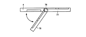
- the display unit 3 includes a fixed display unit 77 and a movable display unit 78.
- the image of the fixed display unit 77 can be captured as a planar image
- the image of the movable display unit 78 can be captured as an aerial image.
- the movable display portion 78 is provided so as to be rotatable from a state inclined with respect to the imaging substrate 4 to a state located on the lower surface of the imaging substrate 4 and along the imaging substrate 4.
- the present invention can be applied to a display device, and is particularly suitable for a display device capable of displaying an aerial image.
- 3 display unit 4 imaging substrate, 5 hinge unit, 6, 7 main surface, 8a, 8b, 8c, 8d reflective surface, 8 mirror surface unit, 9 image, 10 aerial image, 12, 13 beam unit, 14 frame unit, 20 backlight unit, 21 display unit, 22 active matrix substrate, 22 above figure, 23 counter substrate, 24 liquid crystal layer, 25 glass substrate, 26 color filter, 27 counter electrode, 28 black matrix, 29 color layer, 30, 31 beams Part, 40 control part, 41 angle sensor, 50 link mechanism, 51 support bar, 52 support bar, 53 frame, 55 slider mechanism, 58 bellows mechanism, 60 guide member, 70, 71 split display part, 72 hinge part, 73 hinge Part, 77 fixed display part, 78 movable display part.
Landscapes
- Physics & Mathematics (AREA)
- Engineering & Computer Science (AREA)
- Multimedia (AREA)
- Signal Processing (AREA)
- General Physics & Mathematics (AREA)
- Optics & Photonics (AREA)
- Devices For Indicating Variable Information By Combining Individual Elements (AREA)
Abstract
表示装置は、画像を表示可能な画面(2)を有する表示部(3)と、板状に形成された結像基板(4)とを備え、結像基板(4)は、厚さ方向に配列する第1主表面(6)および第2主表面(7)と、第1主表面(6)側から入り込んだ表示部(3)からの光を第2主表面(7)側に向けて反射して第2主表面(7)側で結像させる複数の鏡面部(8)とを含み、鏡面部(8)は、結像基板(4)の厚さ方向に延び、表示部(3)および結像基板(4)は、画面(9)が第1主表面(6)に対して傾斜するように配置され、画面(2)からの光が第1主表面(6)側から結像基板(4)に入り、第2主表面(7)側で結像する第1状態と、表示部(3)と結像基板(4)とが厚さ方向に配列すると共に、互いに沿うように配置された第2状態とに切り替え可能とされる。
Description
本発明は、表示装置に関し、特に、空中映像を表示可能な表示装置に関する。
従来から空中映像を表示可能な表示装置や光学システム等に関して各種提案されている。たとえば、特開2008-158114号公報(特許文献1)に記載された光学システムは、被投影物からの光を面対称位置で結像させる反射型面対称結像素子を有する。
反射型面対称結像素子は、板状に形成されており、反射型面対称結像素子には、複数の穴部が形成されている。穴部の上方から穴部を見ると、穴部は、矩形形状に形成されている。穴部の各内側面には鏡面が形成されており、隣り合う鏡面同士は互いに垂直に交わるように配置されている。
被投影物からの光は、穴部の一方の開口部から穴部内に入り込む。穴部内に入り込んだ光は、穴部内で反射を繰り返して、穴部の他方の開口部から外部に放射される。
他方の穴部から放射される反射光と、穴部内に入り込む入射光とを、反射型面対称結像素子の上方から観察すると、反射光は、入射光と真反対方向に進む。入射光と、反射光とを、反射型面対称結像素子の側方から観察すると、入射光の入射角と、反射光の反射角とは等しくなる。
このため、被投影物からの光は、反射型面対称結像素子を基準面として、面対称となる位置に結像する。
国際公開第2007/116639号(特許文献2)に記載された光学素子は、板状に形成されており、上記特開2008-158114号公報(特許文献1)に記載された反射型面対称結像素子と同様の構成が採用されている。このため、この光学素子は、素子面の一方の面から入り込んだ被投影物からの光を、光学素子を基準面として、面対称となる位置に結像させる。この結果、素子面の他方側の物理的実体のない空間に実像が表示される。
さらに、国際公開第2007/116639号(特許文献2)には、この光学素子を備えた3次元空中映像ディスプレイ装置が記載されている。この3次元空中映像ディスプレイ装置は、反射型映像結像素子として機能する基板と、基板の下側に配置された表示部とを備える。そして、基板の下面から基板内に入り込んだ表示部からの光は、基板の上面の上方で結像される。
特開2009-229905号公報(特許文献3)に記載された3次元空中映像ディスプレイ装置は、2面コーナーリフレクタアレイと、映像を表示する表示面を含むディスプレイとを備える。2面コーナーリフレクタアレイは、対称面となる幾何学平面に対する面対称位置に被投影物の実像を結ぶ。なお、この3次元空中映像ディスプレイ装置は、上記2面コーナーリフレクタアレイを垂直方向に運動させる駆動部を備える。
特開2009-75483号公報(特許文献4)に記載された積走査型3次元空中映像ディスプレイは、2面コーナーリフレクタアレイと、映像を表示する表示面を含むディスプレイと、ディスプレイを表示面に対して垂直方向に移動させる駆動部とを備える。
従来の光学システムや3次元空中映像ディスプレイ装置においては、空中映像を表示する状態と、表示部に表示された平面画像を観察者が直接観察可能な状態とに切り替え可能となっていない。
具体的には、たとえば、特開2009-75483号公報に記載された空中映像ディスプレイにおいて、ディスプレイに表示された画像を観察者が直接確認する場合には、観察者は、ディスプレイの画面に対して垂直な方向から画像を見ようとする。
この場合、観察者は、ディスプレイ上に位置する2面コーナーリフレクタアレイの鏡面を斜め方向から見ることになり、画像の一部が2面コーナーリフレクタアレイの鏡面に覆われることになり、画像を良好に観察することができない。
さらに、板状の2面コーナーリフレクタアレイの素子面に垂直な方向から画像を確認しようとすると、視線は、鏡面の高さ方向と一致することで、鏡面によって画像の一部が覆われることを抑制することができる。その一方で、観察者は、画像を斜め方向から観察することになり、画像を良好に見ることができない。
本発明は、上記のような課題に鑑みてなされたものであって、その目的は、空中映像を表示することができると共に、平面映像も良好に観察者が観察することができる表示装置を提供することである。
本発明に係る表示装置は、画像を表示可能な画面を有する表示部と、板状に形成された結像基板とを備える。上記結像基板は、厚さ方向に配列する第1主表面および第2主表面と、第1主表面側から入り込んだ表示部からの光を第2主表面側に向けて反射して第2主表面側で結像させる複数の鏡面部とを含む。上記鏡面部は、結像基板の厚さ方向に延びる。上記表示部および結像基板は、画面が第1主表面に対して傾斜するように配置され、画面からの光が第1主表面側から結像基板に入り、第2主表面側で結像する第1状態と、表示部と結像基板とが厚さ方向に配列すると共に、互いに沿うように配置された第2状態とに切り替え可能とされた。
好ましくは、上記結像基板には、厚さ方向に延びる複数の穴部が形成され、鏡面部は、穴部の内周面に形成される。上記第2状態において、穴部を通して画面を見ることが可能とされる。
好ましくは、上記表示部は、遮光性を有するブラックマトリックスを含む。上記ブラックマトリックスは、間隔をあけて設けられた複数の線状部分を含む。上記結像基板は、第1主表面に沿って第1方向に延びると共に、第1方向と交差する第2方向に間隔をあけて配置された複数の第1梁部と、第2方向に延びると共に、第1方向に間隔をあけて配置された複数の第2梁部とを含む。上記結像基板には、第1梁部および第2梁部によって囲まれる複数の穴部が形成される。上記鏡面部は、穴部の内周面に形成される。上記第2状態において、表示部と結像基板とを結像基板の上方から見ると、第1梁部または第2梁部の少なくとも一方が、線状部分と重なると共に、線状部分に沿って延びるように配置される。
好ましくは、表示装置は、上記画面と第1主表面との成す角度が可変となるように、表示部および結像基板の少なくとも一方を、第1仮想軸線を中心に回転可能に支持する支持部材と、画像を表示する位置を制御する制御部と、画面と第1主表面との成す角度を検知する検知部とをさらに備える。上記制御部は、画面と第1主表面との成す角度が小さくなるにつれて、第1仮想軸線から離れるように画像を移動させる。
好ましくは、上記第1状態における画面を第1基準画面とし、第1基準画面に表示された画像を基準画像とし、基準画像および結像基板を通る仮想軸線を第2仮想軸線とする。さらに、第1状態から画面と第1主表面との成す角度が小さくなるように表示部が移動したときの画面を第2基準画面とし、第2基準画面と第2仮想軸線との交点を画像表示位置とする。上記制御部は、画像表示位置に画像を移動させる。
好ましくは、上記制御部は、画面と第1主表面との成す角度が小さくなるにつれて、画面の輝度を高くする。
好ましくは、上記第1状態における画面を第1基準画面とし、第1基準画面に表示された画像を基準画像とし、基準画像および結像基板を通る仮想軸線を第2仮想軸線とする。上記制御部は、画面から放射される光のうち、第2仮想軸線を通る光の輝度が一定となるように、画面の輝度を調整する。
好ましくは、上記第1状態における画面を第1基準画面とし、第1基準画面に表示された画像を基準画像とし、基準画像をとおり第1基準画面に対して垂直な仮想軸線を第2仮想軸線とする。上記結像基板と第2仮想軸線との交点を基準交点とし、第1状態から画面と第1主表面との成す角度が小さくなるように表示部が移動したときの画面を第2基準画面とする。上記基準交点をとおり第2基準画面に垂直に交わる仮想軸線を第3仮想軸線とする。上記制御部は、第3仮想軸線と第2基準画面との交点に画像を移動させる。
好ましくは、上記表示部からの光が第1主表面に入射する角度を入射角度とする。上記結像基板の結像成分比は、入射角度が所定の入射角度よりも小さくなるにつれて小さくなる。上記制御部は、所定の入射角度よりも、画面と第1主表面との成す角度が小さくなると、画像の輝度を高くする。
好ましくは、上記結像基板は、表示部の上方から退避可能に設けられる。
好ましくは、上記表示部は、第1表示部および第2表示部を含む。上記第1表示部および第2表示部の少なくとも一方が、第2状態と第1状態とに切り替え可能とされる。好ましくは、上記表示部は、第2状態において結像基板の第2主表面上に位置する。
好ましくは、上記表示部は、第1表示部および第2表示部を含む。上記第1表示部および第2表示部の少なくとも一方が、第2状態と第1状態とに切り替え可能とされる。好ましくは、上記表示部は、第2状態において結像基板の第2主表面上に位置する。
本発明に係る表示装置によれば、空中映像を表示することができると共に、平面映像も良好に観察者が観察することができる。
図1から図36を用いて、本発明に係る表示装置について説明する。
(実施の形態1)
図1は、本実施の形態1に係る表示装置1の概略構成を示す斜視図であり、図2は、表示装置1の概略構成を示す側面図である。
(実施の形態1)
図1は、本実施の形態1に係る表示装置1の概略構成を示す斜視図であり、図2は、表示装置1の概略構成を示す側面図である。
図1に示すように、表示装置1は、画像を表示可能な画面2を有する表示部3と、結像基板4と、ヒンジ部5とを含む。結像基板4および表示部3は、少なくとも一方が他方に対して、回転中心線(仮想軸線)O1を中心に回転可能なように、ヒンジ部5によって支持されている。なお、本実施の形態においては、ヒンジ部5は、表示部3の外周辺の一辺に設けられており、表示部3は回転中心線O1を中心に回転可能なようにヒンジ部5によって支持されている。
なお、図1に示す状態では、表示部3の画面2は、結像基板4に対して傾斜するように配置されている。
図2において、結像基板4は、平板状に形成されており、結像基板4の厚さ方向に配列する主表面6および主表面7と、複数の鏡面部8とを含む。なお、結像基板4には、結像基板4の厚さ方向に延び、主表面6から主表面7に達する複数の穴部が形成されており、この穴部の内周面に鏡面部8が形成されている。鏡面部8は、結像基板4の厚さ方向に延びており、鏡面部8の高さ方向は、結像基板4の厚さ方向と一致している。なお、穴部および鏡面部8は、結像基板4に均等に分布している。
主表面6は、表示部3の画面2と対向するように設けられており、画面2に表示された画像9からの光は、上記穴部の開口部から結像基板4内に入り込む。
ここで、画像9をとおり、画面2に垂直な仮想軸線を仮想軸線A1とし、結像基板4の厚さ方向に延びる仮想軸線を仮想軸線A2とする。さらに、仮想軸線A1と仮想軸線A2との交差角度のうち、小さい方の交差角度を交差角度θとする。なお、交差角度θは、表示部3が回転中心線O1を中心に回転することで変化し、結像基板4および表示部3の開成角度に相当する。
この図1および図2に示す状態においては、画像9からの光は、主表面6から結像基板4内に入り込み、鏡面部8によって主表面7側に向けて反射される。反射した光は、主表面7の上方で結像し、空中映像10が表示される。
ここで、結像基板4の厚さ方向の中央部をとおり、鏡面部8と垂直に交わる仮想平面を仮想平面P1とすると、空中映像10は、仮想平面P1を基準面として、画像9の面対称となる位置に結像する。
たとえば、図2に示すように、画像9からの光のうち画面2に対して垂直な方向に進む光R1は、鏡面部8Aによって反射され、画像9から放射された任意の光R0は、鏡面部8Bによって反射される。光R1の反射光と、光R0の反射光とは、空中映像10が位置する部分で交わっており、当該焦点位置で結像することが分かる。
この図2に示す例においては、空中映像10は、主表面7の上方に位置している。空中映像10と仮想平面P1との間の距離は、画像9と仮想平面P1との間の距離と等しくなる。交差角度θが大きくなるように、表示部3が回転することで、結像基板4と表示部3との開成角度が大きくなる。そして、画像9と仮想平面P1との間の距離が大きくなり、空中映像10をより高く浮かせることができる。このように、交差角度θを調整することで、表示される空中映像10が浮き上がる高さを調整することができる。
図3は、交差角度θが図2に示す状態から小さくなるように、表示部3を回転させた状態を示す側面図である。この図3に示すように、交差角度θが小さくなると、画像9と仮想平面P1との間の距離が短くなり、空中映像10の浮き上がる高さも低くなる。
さらに、交差角度θが小さくなるように、表示部3を回転させ、交差角度θが0度となったときの状態を図4に示す。この図4に示す状態においては、結像基板4の主表面6の下面側に表示部3が位置し、表示部3および結像基板4とが結像基板4の厚さ方向に配列し、互いに沿うように配置されている。そして、表示部3の画面2と、結像基板4の主表面6とは互いに沿うように配置され、鏡面部8Aおよび鏡面部8Bの高さ方向と、画面2に垂直な仮想軸線A1とが平行となる。この図4に示すように、交差角度θが0度のときにおいて、観察者が結像基板4の上方から画像9を平面視すると、観察者の視線は鏡面部8の高さ方向と平行となる。
このため、交差角度θが0度のときにおいて、観察者が結像基板4の上方から画像9を平面視すると、鏡面部8が画像9を覆うことを抑制することができ、観察者は良好に画像9を観察することができる。
図5は、結像基板4を示す斜視図である。この図5に示すように、結像基板4には、複数の穴部11が形成されている。穴部11は、アレイ状に配置されている。結像基板4は、第1方向D1に延びる梁部12と、第2方向D2方向に延びる梁部13と、結像基板4の外周縁部に配置された枠部14とを含む。梁部12は、第2方向D2に間隔をあけて複数配列しており、梁部13も第1方向D1に間隔をあけて複数配置されている。各梁部12,13の両端部は、枠部14に接続されている。なお、第1方向D1は、結像基板4の主表面に沿って延び、第2方向D2は、結像基板4の主表面に沿って延びると共に、第1方向D1と直交する方向である。
各穴部11は、隣り合う2つの梁部12と、隣り合う2つの梁部13とによって形成されている。穴部11は、結像基板4を貫通し、結像基板4の厚さ方向に延びている。鏡面部8は、穴部11の内周面に形成されている。
図6は、結像基板4の一部を示す斜視図である。この図6に示すように、隣り合う鏡面部8の間には、梁部12または梁部13が位置する。結像基板4の主表面6には穴部11の開口部16が形成され、主表面7には、開口部17が形成されている。図7は、1つの鏡面部8を示す斜視図である。この図7に示すように、鏡面部8は、4つの反射面8a~8dを含む。反射面8aと反射面8cとは互いに間隔をあけて設けられており、互い対向するように配置されている。反射面8cと反射面8dとは互いに間隔をあけて設けられており、互いに対向するように配置されている。反射面8bは、反射面8aの一辺と反射面8cの一辺を接続するように配置され、反射面8dは、反射面8aの他辺と反射面8cの他辺とを接続するように配置されている。反射面8aは、反射面8bおよび反射面8dと垂直に交わり、反射面8cも、反射面8bおよび反射面8dと垂直に交わる。反射面8a,8cは、いずれも、第2方向D2に延び、反射面8b,8dは、第1方向D1に延びる。
反射面8a~8dは、開口部17から開口部16に達するように形成されており、反射面8a~反射面8dは結像基板4の厚さ方向に延びている。
なお、たとえば、鏡面部8は、結像基板4の5cm×5cmの中に、たとえば、数万個から数十万個ほど形成されている。
なお、穴部11の開口縁部に位置する各反射面8a~8dの一辺の長さは、たとえば、50~1000μmとされ、好ましくは、150μmとされる。さらに、反射面8a~8dの高さは、たとえば、50μm~1000μmとされ、好ましくは、150μmとされる。
図2および図8を用いて、画像9からの光が結像するまでの経路について説明する。画像9を構成する1つの光源(画素)15からの光のうち、画像9から任意の方向の光R0と、画像9から垂直な方向の光R1とに着目する。光R0は、入射光IR1,IR2を含み、光R1は、入射光IR3,IR4を含む。
入射光IR1は、図6に示す開口部16から穴部11内に入り込み、反射面8aによって反射される。この反射光は、反射面8bによって再度反射される。反射面8bによって反射された反射光RL1は、図6に示す開口部17から外部に放射される。入射光IR2は、反射面8bによって反射され、この反射光は、反射面8aによって再度反射される。そして、反射光RL2として、外部に放射される。
反射光RL1と、入射光IR1とを結像基板4の上方から平面視すると、反射光RL1と入射光IR1とは平行であって、反射光RL1の進行方向と入射光IR1の進行方向とは真逆となってる。同様に、反射光RL2と入射光IR2とは、互いに平行であって、互いの進行方向は真逆となっている。
そして、図2に示すように、鏡面部8は、光R0の垂直成分を変化させずに反射する。このため、図8に示すように、結像基板4を平面視した状態において、光R0の反射光の一部は、光源15の上方に位置する焦点領域FAを通る。
同様に、鏡面部8は、光R1の入射光IR3を反射光RL3として反射し、入射光IR4を反射光RL4として反射する。反射光RL3は、入射光IR3と平行であって、反射光RL3の進行方向は入射光IR3の進行方向と真逆となる。同様に、反射光RL4も、入射光IR4と平行であって、反射光RL4の進行方向は入射光IR4の進行方向と真逆となる。このため、光R1の反射光も、焦点領域FAを通る。
上記のように結像基板4に入射される光源15からの光は、結像基板4によって再起反射され、焦点領域FAにおいて結像する。この結果、図2に示すように、空中映像10が所定の位置に結像される。
なお、焦点領域FAの大きさは、鏡面部8の大きさに起因しており、鏡面部8を微細化することで焦点領域FAの大きさを小さくすることができる。その一方で、鏡面部8が小さくなるにしたがって、開口率(光が通過できる面積比)が低下し、空中映像の輝度が低下する。また、光の回折が生じ、却って、空中映像の解像度が落ちる。そのため、集光距離に応じて、鏡面部8の大きさは適宜設定される。
図9は、表示部3を模式的に示す断面図である。表示部3は、バックライトユニット20と、このバックライトユニット20の上面上に配置された表示ユニット21とを含む。バックライトユニット20は、表示ユニット21に向けて光を放射する。
表示ユニット21は、バックライトユニット20の上面上に配置されるアクティブマトリックス基板22と、アクティブマトリックス基板22から間隔をあけて配置され、アクティブマトリックス基板22と対向するように配置された対向基板23と、対向基板23およびアクティブマトリックス基板22の間に封入された液晶層24とを含む。
なお、アクティブマトリックス基板22とバックライトユニット20との間には、偏光板(図示せず)が配置されており、対向基板23の上面にも、偏光板(図示せず)が配置されている。各偏光板が透過する光の振動方向は、互いに直交するように形成されている。
対向基板23は、ガラス基板25と、このガラス基板25の下面に形成されたカラーフィルタ26と、カラーフィルタ26の下面に配置された対向電極27とを含む。カラーフィルタ26は、ブラックマトリックス28と、色層29と含む。ブラックマトリックス28は、格子状に形成されており、ブラックマトリックス28には、複数の窓部が形成されている。色層29は、この窓部に形成されている。
アクティブマトリックス基板22は、複数のTFTトランジスタ(図示せず)と、TFTトランジスタのゲート電極に接続されたゲート配線と、TFTトランジスタのソース電極に接続されたソース配線と、TFTトランジスタのドレイン電極に接続された画素電極とを含む。格子状に形成されたブラックマトリックス28の下方に、ゲート配線やソース配線が配置されている。
そして、TFTトランジスタのON/OFFを切り替えることで、画素電極に電圧が印加されたり、電圧が印加されなかったりする。対向電極と画素電極との間の電圧によって、画素電極と対向電極との間に位置する液晶層内の液晶の配列方向が切り替えられる。
そして、バックライトユニット20からの光が、図示されない偏光板を通ることで、光の振動方向が揃えられる。その後、液晶の配列状態によって、光の振動方向が変化する。この結果、液晶層24を通過した光が対向基板23上に位置する偏光板を通過可能であったり、偏光板によって遮光されたりする。
そして、バックライトユニット20の光が、対向基板23の上面上の偏光板を通過するときには、バックライトからの光は既に、色層29を通過している。このため、色層29の色に対応する着色光が外部に放射される。
なお、この図9に示す例においては、カラーフィルタ26は、対向基板23側に設けられているが、アクティブマトリックス基板22に設けてもよい。
図10は、カラーフィルタ26の一部を模式的に示す平面図である。この図10に示すように、カラーフィルタ26は、ブラックマトリックス28と、色層29とを含む。ブラックマトリックス28は、第1方向D1に延び、第2方向D2に間隔をあけて複数設けられた梁部30と、第2方向D2に延び、第1方向D1に間隔をあけて複数設けられた梁部31とを含む。
隣り合う2つの梁部30と、隣り合う2つの梁部31とによって、窓部が形成されている。各窓部には、色層29が形成されている。色層29は、赤色の色層29rと、緑色の色層29gと、青色の色層29bとを含む。なお、この図10は、模式的に示した図であって、各梁部30,31の幅や色層29の大きさなどを正確に示す図ではない。
図11は、結像基板4の一部を模式的に示す平面図である。この図11に示すように、結像基板4は、第1方向D1に延び、第2方向D2に間隔をあけて設けられた複数の梁部12と、第2方向D2に延び、第1方向D1に間隔をあけて設けられた複数の梁部13とを含む。隣り合う2つの梁部12および隣り合う2つの梁部13とによって、穴部11が形成されている。
図12は、上記図4に示すように、表示部3と結像基板4とを貼り合わせたような状態において、結像基板4の上方から結像基板4および表示部3を平面視したときの平面図である。
この図12および図4において、結像基板4の梁部12の下方に、ブラックマトリックス28の梁部30が位置しており、結像基板4の梁部13の下方に、ブラックマトリックス28の梁部31が位置している。梁部30が梁部12に沿って延び、梁部31が梁部13に沿って延びている。そして、穴部11内に色層29が位置している。
このように、色層29上に結像基板4の梁部12,13が位置することが抑制されている。なお、結像基板4の梁部12および梁部13のいずれもが、ブラックマトリックス28の梁部30または梁部31の上方に位置する必要はなく、結像基板4の梁部12および梁部13の一方がブラックマトリックス28の梁部30または梁部31の上方に位置し、梁部30または梁部31に沿って延びるようにしてもよい。
結像基板4の梁部12および梁部13の幅は、たとえば、10μmとされ、ブラックマトリックス28の梁部30および梁部31の幅も、たとえば、10μm程度とされている。好ましくは、結像基板4の梁部12,13の幅をブラックマトリックス28の梁部30,31の幅よりも小さくする。
図13は、図4に示す状態で、画像を表示したときの模式図である。なお、この図13において、梁部12および梁部13を分かり易く標記しており、実際は、梁部12および梁部13は、視認できない程度の太さである。図4に示すように、仮想軸線A1と仮想軸線A2との交差角度θが0度のとき(仮想軸線A1と仮想軸線A2とが平行となるとき)には、図13に示すように、鏡面部8は、カラーフィルタ26に対して垂直に立ち上がるように配置される。このため、結像基板4の真上から結像基板4を平面視すると、反射面8a~8d(梁部12,13の側面)が観察されない。
このため、図4に示すように、結像基板4と表示部3とを貼り合わせた状態で、結像基板4の上方から表示部3に表示された画像9を観察するときには、図13に示すように画像9を良好に観察することができる。
図14は、図2に示す視点32から視線方向33に画像9を見たときの様子を示す模式図である。なお、図2に示す視線方向33は、画面2に垂直な方向であり、視点32は、画像9をとおる仮想軸線A1の延長上に位置している。その一方で、鏡面部8は、仮想軸線A2方向に延びており、視線方向33と仮想軸線A2の延在方向とは、互いに交差する方向となっている。
このため、図14に示すように、観察者は、傾いた鏡面部8の穴部11を通して、画像9を観察することになる。この結果、図14からも明らかなように、観察者が画像9を観察したときには、鏡面部8が画像9の一部を覆うことになり、画像9を良好に確認することができないことがわかる。
さらに、図2において、視点34から視線方向35に画像9を観察したときについて説明する。図15は、視点34から視線方向35に画像9を観察したときの様子を示す模式図である。この図15および図2において、視線方向35は、結像基板4の厚さ方向と平行となっているため、鏡面部8の反射面によって画像9が隠されていない。その一方で、画像9が表示されている表示部3は、傾斜しているため、観察者は画像9を斜め方向から観察することになる。この結果、図15に示すように画像9を正確に観察することができない。
その一方で、仮想軸線A1と仮想軸線A2との交差角度θが小さくなるように表示部3を回転させると、画面2が結像基板4の主表面6に沿うように移動する。この結果、視点34から画像9を観察すると、傾斜していた画像9が起きはじめ、画像9を良好に観察することができるようになる。
そして、仮想軸線A1および仮想軸線A2の交差角度が0度となるときには、上記図13のように、良好に画像9を観察することができる。
なお、図2において、表示部3の液晶表示装置として、正面白色輝度が約1000cd/cm2の液晶表示装置を採用し、交差角度θが60°のとき、視点18から視線方向19に空中映像10を観察すると、空中映像10の輝度は、約200cd/cm2であった。そして、空中映像10を良好に観察することができた。さらに、図4に示す状態で、画像9を結像基板4の上方から平面視すると、画像9の輝度は、約800cd/cm2であった。そして、画像9を良好に観察することができた。
(実施の形態2)
図16から図19を用いて、本実施の形態2に係る表示装置1について説明する。なお、図16から図19に示す構成のうち、上記図1から図15に示す構成と同一または相当する構成については、同一の符号を付してその説明を省略する場合がある。
図16から図19を用いて、本実施の形態2に係る表示装置1について説明する。なお、図16から図19に示す構成のうち、上記図1から図15に示す構成と同一または相当する構成については、同一の符号を付してその説明を省略する場合がある。
図16は、本実施の形態2に係る表示装置1を模式的に示す斜視図である。この図16に示すように、結像基板4は、結像基板4に対して垂直に延び、結像基板4の中心を通る回転中心線O2を中心に回転可能に設けられている。なお、この図16に示す状態は、表示部3がヒンジ部5を中心に回転しており、表示部3が結像基板4から離れている。このため、画面2に表示された画像は、結像基板4の上方に結像する。
図17は、図16の状態において、結像基板4の上方から結像基板4および画面2を見たときの結像基板4および画面2を模式的に示す模式図である。
この図17に示すように、空中画像を表示する際には、結像基板4の梁部12と、ブラックマトリックス28の梁部31とは、略45度に交差している。同様に、結像基板4の梁部13と、ブラックマトリックス28の梁部30とは、略45度程度で交差している。
図18は、図16に示す状態から表示部3と結像基板4とを貼り合わせるように、表示部3を回転させた状態を示す斜視図である。なお、この図18に示す状態において、観察者が、結像基板4の上方から表示部3に表示された画像を観察するときには、結像基板4を回転中心線O2を中心に回転させる。
図19は、上記図18に示すように、表示部3および結像基板4を貼り合わせた状態において、結像基板4を回転させた状態を示す模式図である。なお、この図19においても結像基板4の上方から結像基板4および表示部3を見たときの模式図である。
図19に示すように、結像基板4を回転させることで、結像基板4の梁部12が、ブラックマトリックス28の梁部31に対して表示部3および結像基板4の積層方向に重なると共に、梁部12が梁部31に沿って延びるように配置される。同様に、結像基板4の梁部13と、ブラックマトリックス28の梁部30とが、積層方向に重なると共に、梁部13が梁部31に沿って延びる。これにより、表示部3および結像基板4を貼り合わせた状態で、結像基板4の上方から画像を見たときには、良好に画像を確認することができる。
(実施の形態3)
図20および図21を用いて、本実施の形態3に係る表示装置1について説明する。なお、図20および図21に示す構成のうち、上記図1から図19に示す構成と同一または相当する構成については同一の符号を付してその説明を省略する。
図20および図21を用いて、本実施の形態3に係る表示装置1について説明する。なお、図20および図21に示す構成のうち、上記図1から図19に示す構成と同一または相当する構成については同一の符号を付してその説明を省略する。
図20は、本実施の形態3に係る表示装置1において、交差角度θを順次変化させたときの結像位置を示す側面図である。
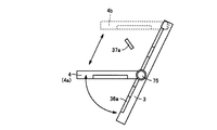
なお、図20に示す例においては、結像基板4は、主表面7と主表面6とが平行な板状とされている。このため、仮想平面P1は、主表面7と主表面6との中間位置を通る。また、表示部3も板状に形成されており、表示部3の厚さ方向の中央部を通る仮想平面P2は、画面2と平行となっている。そして、ヒンジ部5によって、表示部3は回転中心線O1を中心に回転可能に設けられている。仮想平面P2は、回転中心線O1を通るように設けられている。表示部3aは、交差角度θが、たとえば、交差角度θ0となるときの表示部3を示し、表示部3bは、交差角度θが、たとえば、交差角度θ1(<θ0)となるときの表示部3を示す。表示部3cは、交差角度θが0度のときの表示部3を示す。
表示装置1は、画面2に表示される画像の位置を制御する制御部40と、主表面6および画面2の交差角度を測定する角度センサ41とを備えている。角度センサ41は、センシングした交差角度に対応する角度信号を制御部40に伝達する。制御部40は、センシングした交差角度に基づいて、表示する画像の輝度などを調整しており、制御部40の機能については後述する。
主表面7および主表面6は平行なため、結像基板4の厚さ方向に延びる仮想軸線A2と、主表面6とは垂直に交わる。さらに、仮想軸線A1は、画面2に垂直な仮想軸線であるため、結像基板4の主表面6と、表示部3の画面2との交差角度は、仮想軸線A1および仮想軸線A2の交差角度θとなる。
表示部3aにおいて、画面2に画像36aが表示されている。画像36aの空中映像37aは、仮想平面P1(結像基板4)を基準面として、面対称となる位置に結像される。
ここで、画像36aからの光のうち、画面2に垂直な方向に放射される光R1は、結像基板4の鏡面部8によって反射光R2として反射される。反射光R2は、その後、結像位置を通って、観察者の目に達する。
表示部3aの状態から表示部3が回転中心線O1を中心に回転して、仮想軸線A1および仮想軸線A2の交差角度が交差角度θ1となったときについて説明する。
図中の表示部3bは、交差角度θ1のときの表示部である。表示部3bの画面2に垂直な仮想軸線を仮想軸線A3とすると、仮想軸線A3と仮想軸線A2との交差角度が交差角度θ1となる。
この表示部3bの画面2と、上記光R1との交点を交点Qとする。回転中心線O1と画像36aとの間の距離を「L」とし、交点Qと回転中心線O1との間の距離を「X」とすると、「X」は下記式(1)を満たす。
X=L×cos-1(θ0-θ1)・・・(1)
このため、「X」は、「L」よりも大きくなり、交点Qと回転中心線O1との間の距離は、画像36aと回転中心線O1との間の距離よりも大きくなる。
このため、「X」は、「L」よりも大きくなり、交点Qと回転中心線O1との間の距離は、画像36aと回転中心線O1との間の距離よりも大きくなる。
制御部40は、表示部3aにおいて表示されていた画像36aを交点Qに表示する。すなわち、制御部40は、交差角度θが交差角度θ0よりも小さくなるにつれて、表示する画像を回転中心線O1から離すように移動させる。
交点Qに表示された画像36bからの光は、結像点Q1において結像し、画像36bは空中映像37bとして表示される。
画像36bから放射される光のうち、光R3は、上記光R1と同一の経路を通る。そして、光R3は、鏡面部8によって反射光R4として反射される。反射光R4は、反射光R2と同一の経路を通る。そして、反射光R4は、結像点Q1を経由して、観察者の目で捉えられる。
このため、観察者は、空中映像37aを観察している状態から視点および観察方向を変更せずとも、空中映像37bを確認することができ、表示部3が回転したとしても、観察者は、同一の視点から空中映像を確認することができる。
図21は、1つの画素において、光の放射角度と、輝度との関係を模式的に示すグラフである。この図21に示すグラフにおいて、横軸は、光軸を基準として、放射される光の放射角度(°)を示し、縦軸は、光の輝度を示す。なお、光軸は、画面2に対して垂直な方向に延びる。
この図21に示すように、放射角度が0°の光が最も輝度が高く、放射角度が大きくなるにつれて、輝度が小さくなる。ここで、図20において、光R1は、画面2に垂直な方向に進んでおり、画像36aから放射される光のうち、最も輝度が高くなっている。
そして、画像36bから放射される光のうち、表示部3bの画面2に垂直な方向に放射される光が最も輝度が高く、光R3は、この光よりも輝度が低いことがわかる。
制御部40は、交差角度θが交差角度θ0よりも小さくなるにつれて、画像を表示する画素の輝度を高くする。これにより、交差角度θが小さくなったとしても、観察者の目が捉える光の輝度が一定に保たれ、表示される空中映像の輝度も一定に保つことができる。
図22は、結像基板4の結像成分比と、光の入射角度との関係を示すグラフである。この図22に示すグラフにおいて、横軸は、表示部からの光が主表面6に入り込むときの入射角度を示す。縦軸は、結像成分比を示す。「結像成分比」とは、被投影物(例えば表示パネル)からの光のうち結像に寄与する光の割合をいう。結像成分比が100%に近いほど被投影物からの光は効率よく反射型結像素子で結像され、空中映像の視認性が高い。
なお、図20からも明らかなように、表示部からの光が主表面6に入り込むときの入射角度と交差角度θとは等しくなる。図22に示すように、入射角度(交差角度θ)が55°以上67°以下のときに、結像成分比が高くなっていることがわかる。
表示装置1が、空中映像を表示するときには、好ましくは、交差角度θを55°以上67°以下とする。特に、好ましくは、空中映像を表示するときには、交差角度θを60°とする。具体的には、図20において、交差角度θ0を60°とする。
交差角度θ0を60°とすることで、画像36aから発せられる光のうち、最も輝度の高い光R1の入射角度が60°となる。このため、最も輝度の高い光が効率よく反射されることで、空中映像37bの視認性の向上をさらに図ることができる。
なお、本実施の形態3においては、観察者の視点は一定の位置に固定されている場合について説明したが、当然のことながら、交差角度θの変化に合わせて、観察者が視点を異ならせる場合も考えられる。
(実施の形態4)
観察者は見ている空中映像が暗くなると、視点の位置をかえて、明るい空中映像が見れる位置を模索することが多い。この実施の形態4に係る表示装置1は、交差角度θが変動したとしても、表示される空中映像の輝度を高く維持することができる表示装置1について説明する。
観察者は見ている空中映像が暗くなると、視点の位置をかえて、明るい空中映像が見れる位置を模索することが多い。この実施の形態4に係る表示装置1は、交差角度θが変動したとしても、表示される空中映像の輝度を高く維持することができる表示装置1について説明する。
図23および上記図22を用いて本発明の実施の形態4に係る表示装置1について説明する。図23に示す構成のうち、上記図1から図22に示す構成と同一または相当する構成については、同一の符号を付してその説明を省略する。この図23において、表示部3aは、交差角度θが60°となる位置に配置されている。
この表示部3aの画面2には、画像36aが表示されている。この画像36aからの光は、結像基板4によって、結像し、空中映像37aが表示される。
画像36aから放射される光のうち、仮想軸線A1を通る光R1は、輝度が高い。この光R1は、結像基板4によって反射光R2として反射され、空中映像37aが位置する焦点を通る。観察者は、視点45において、反射光R2を捉え、空中映像37aを観察している。観察者は、光R1を捉えることで空中映像37aを認識しており、空中映像37aの輝度は高くなっている。
仮想軸線A1は、画像36aをとおり、画面2に垂直な仮想軸線である。この仮想軸線A1と、結像基板4との交点を基準交点Fとする。
表示部3bは、表示部3aが回転中心線O1を中心に回転して、交差角度θが60°よりも小さくなったときの表示部である。
基準交点Fをとおり、表示部3bの画面2に垂直に交わる仮想軸線を仮想軸線A4とする。この仮想軸線A4と表示部3bの画面2との交点を交点Q2とする。
制御部40は、表示部3bの画面2に表示する画像を交点Q2に移動させる。交点Q2に表示された画像36cは、結像基板4によって、結像点Q3に結像する。結像点Q3において、空中映像37cが表示される。
画像36cから放射される光のうち、仮想軸線A4を通る光R5が最も輝度が高い。この光R5は、基準交点Fに位置する鏡面部8によって反射光R6として反射される。反射光R6は、基準交点Fから、結像点Q3を通るように進む。
視点45では、空中映像37cからの光を確認できなかったり、空中映像37cからの光を良好に捉えることができない。
このため、観察者は空中映像37cを明確に確認することができる位置に視点をずらす。視点46から基準交点Fを見ると、反射光R6を観察者は捉えることができる。
上記のように、反射光R6の輝度は高いため、観察者ははっきりと空中映像37cを捉えることができる。
ここで、空中映像37aが表示されているときにおいて、最も輝度の高い反射光R2は、基準交点Fを通る。空中映像37cが表示されているときにおいて、最も輝度の高い反射光R6も基準交点Fを通る。
観察者は、表示部3が移動したときにおいても、基準交点Fを見ながら、視点の位置を変えることで、輝度の明るい空中映像を再度捉えることができる。このように、観察者は、表示部3が回転することで見ている空中映像の輝度が低くなったとしても、簡単に輝度の高い空中映像を探し当てることができる。
図22において、入射角度が60°よりも小さくなると、入射角度が小さくなるにつれて、結像基板4の結像成分比は小さくなることがわかる。
上記のように、図22の入射角度とは、画面2からの光が鏡面部8に入射するときの入射角度であり、この入射角度は、交差角度θと実質的に同じ角度となる。
制御部40は、交差角度θが60°よりも小さくなると、交差角度θが小さくなるにつれて、表示する画像の輝度を高くする。これにより、表示部3が回転移動することで表示される空中画像の輝度が低くなることを抑制することができる。
実施の形態1~3においては、結像基板4の一例を用いて説明したが、図24に示すような結像基板4も採用することができる。
図24に示す例においては、結像基板4は、平板状の基板48と、この基板48の主表面上にアレイ状に配置された複数の筒部47と、この筒部47の内周面に形成された鏡面部8とを含む。筒部47は、基板48の厚さ方向に延びる。筒部47の内周面は、4つの内平面から形成されており、隣り合う内平面は互いに直交するように配置されている。そして、各内平面には、鏡面部が形成されている。
(実施の形態5)
図25から図36を用いて、表示装置1の各種変形例について説明する。なお、この図25から図36に示す構成のうち、上記図1から図24に示す構成と同一または相当する構成については、同一の符号を付して、その説明を省略する場合がある。図25は、表示装置1の第1変形例を模式的に示す側面図である。
図25から図36を用いて、表示装置1の各種変形例について説明する。なお、この図25から図36に示す構成のうち、上記図1から図24に示す構成と同一または相当する構成については、同一の符号を付して、その説明を省略する場合がある。図25は、表示装置1の第1変形例を模式的に示す側面図である。
この図25に示す表示装置1は、結像基板4と、結像基板4を支持するフレーム53と、表示部3およびフレーム53を連結するリンク機構50と、ヒンジ部5とを含む。
リンク機構50は、支持バー51および支持バー52を含む。支持バー51の一端部は、フレーム53に回転可能に支持されており、支持バー52の一端部は、表示部3に回転可能に支持されている。支持バー51の他端部と支持バー52の他端部とは、互いに回転可能に連結されている。
図26は、表示装置1の第2変形例を模式的に示す側面図である。この図26に示す例においては、スライダ機構55によって、表示部3が支持されている。
図27は、表示装置1の第3変形例を示す側面図である。この図27に示す例においては、表示部3と結像基板4とが蛇腹機構58によって連結されている。この蛇腹機構58は、扇型形状の複数の遮光板を含み、隣り合う遮光板同士は、互いにスライド移動可能なように連結されている。ヒンジ部5に回転可能に設けられている。
このため、表示装置1が空中映像を表示する際に、外部からの光が結像基板4に入り込むことを抑制したり、表示部3の画面に異物が付着することを抑制することができる。
図28は、表示装置1の第4変形例を示す平面図である。この図28に示す例においては、表示装置1は、表示部3と、結像基板4と、表示部3および結像基板4の少なくとも一方を他方に対して回転可能に支持するヒンジ部5と、結像基板4を案内する案内部材60とを備える。結像基板4は、案内部材60によって、表示部3の上方から退避可能とされている。このため、観察者は、平面画像を見るときには、表示部3の上方から結像基板4を退避させることで、表示部3に表示された平面画像を直接観察することができる。
なお、図28に示す例においては、結像基板4は、ヒンジ部5の延在方向に対して直交する方向にスライド移動可能に設けられているが、結像基板4が移動可能な方向としては、この方向に限られない。
たとえば、図29に示すように、ヒンジ部5の延在方向と平行な方向にスライド移動可能なようにしてもよい。
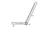
図30は、表示装置1の第5変形例を模式的に示す側面図である。この図30に示す例においては、表示部3はヒンジ部5によって回転可能に設けられており、表示部3は、図中の表示部3aに示す状態から、図中の表示部3cに示す状態となるまで回転可能に支持されている。
表示部3aは、結像基板4の主表面6の下方に位置しており、表示部3aの画面2からの光が、主表面6から結像基板4内に入り込む。当該光は、結像基板4によって、反射され、主表面7の上方で結像する。
表示部3cは、結像基板4の主表面7上に位置している。画面2は、上方に向けられており、観察者は、画面2を直接観察することができる。
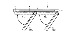
図31は、表示装置1の第6変形例を模式的に示す側面図である。この図31に示す例においては、表示部3は、複数の分割表示部70,71を含む。分割表示部70は、ヒンジ部72によって回転可能に設けられており、分割表示部71は、ヒンジ部73によって回転可能に設けられている。
分割表示部70は、図中の分割表示部70aに示す状態から図中の分割表示部70cに示す状態となるまで回転可能に設けられている。分割表示部70aは、画面が結像基板4の主表面6に対して傾斜するように配置されている。分割表示部70cは、主表面6の下方に位置しており、分割表示部70cと結像基板4とは互いに沿うように位置している。
分割表示部71も、図中に示す分割表示部71aに示す状態から図中の分割表示部71cに示す状態となるまで回転可能に設けられている。
分割表示部71aは、主表面6の下方に位置しており、分割表示部71aの画面が主表面6に対して傾斜するように配置されている。分割表示部71cは、主表面6の下方に位置しており、分割表示部71cおよび結像基板4は互いに沿うように配置されている。
この図31に示す例によれば、表示装置1のコンパクト化を図ることができる。
図32は、図31に示す表示装置1の変形例を示す側面図である。この図32においては、分割表示部70が図中の分割表示部70aに示す状態(第1状態)から図中の分割表示部70cに示す状態(第2状態)となるときの回転方向と、分割表示部71が図中の分割表示部71aに示す状態(第1状態)から図中の分割表示部71cに示す(第2状態)となるときの回転方向とが反対となるように設けられている。このように、各分割表示部の回転方向を分割表示部ごとに異ならせてもよい。
図32は、図31に示す表示装置1の変形例を示す側面図である。この図32においては、分割表示部70が図中の分割表示部70aに示す状態(第1状態)から図中の分割表示部70cに示す状態(第2状態)となるときの回転方向と、分割表示部71が図中の分割表示部71aに示す状態(第1状態)から図中の分割表示部71cに示す(第2状態)となるときの回転方向とが反対となるように設けられている。このように、各分割表示部の回転方向を分割表示部ごとに異ならせてもよい。
図33は、表示装置1の第7変形例を示す模式図である。図33に示す例においては、結像基板4は、表示部3の画面に対して傾斜した状態で表示部3に対してスライド移動可能なように設けられている。これにより、表示部3の画面に表示された画像を選択して、空中映像として表示させることができる。さらに、この図33に示す例においては、結像基板4は、回転可能に設けられており、結像基板4を表示部3上に配置することができる。この際、結像基板4と表示部3とは、結像基板4の厚さ方向に配列し、互いに沿うように配置されている。
図34および図35は、図33に示す表示装置1の変形例を示す模式図である。図34中の結像基板4cに示すように、結像基板4は表示部3の端部までスライド移動可能に設けられている。さらに、図35中の結像基板4dに示すように、結像基板4は、表示部3の端部で回転し、表示部3の背面側に移動可能に設けられている。
この図34および図35に示す例によれば、観察者は、表示部3の画面に表示された画像を直接確認することができる。
図36は、表示装置1の第8変形例を模式的に示す側面図である。この図36に示すように表示部3は、固定表示部77と、可動表示部78とを含む。これにより、固定表示部77の画像を平面画像として捉えることができると共に、可動表示部78の画像を空中画像として捉えることができる。なお、可動表示部78は、結像基板4に対して傾斜した状態から、結像基板4の下面に位置し、結像基板4に沿うような状態にまで回転可能に設けられている。
以上のように本発明の実施の形態について説明を行なったが、今回開示された実施の形態はすべての点で例示であって制限的なものではないと考えられるべきである。本発明の範囲は請求の範囲によって示され、請求の範囲と均等の意味および範囲内でのすべての変更が含まれることが意図される。さらに、上記数値などは、例示であり、上記数値および範囲にかぎられない。
本発明は、表示装置に適用することができ、特に、空中映像を表示可能な表示装置に好適である。
3 表示部、4 結像基板、5 ヒンジ部、6,7 主表面、8a,8b,8c,8d 反射面、8 鏡面部、9 画像、10 空中映像、12,13 梁部、14 枠部、20 バックライトユニット、21 表示ユニット、22 アクティブマトリックス基板、22 上記図、23 対向基板、24 液晶層、25 ガラス基板、26 カラーフィルタ、27 対向電極、28 ブラックマトリックス、29 色層、30,31 梁部、40 制御部、41 角度センサ、50 リンク機構、51 支持バー、52 支持バー、53 フレーム、55 スライダ機構、58 蛇腹機構、60 案内部材、70,71 分割表示部、72 ヒンジ部、73 ヒンジ部、77 固定表示部、78 可動表示部。
Claims (12)
- 画像を表示可能な画面(2)を有する表示部(3)と、
板状に形成された結像基板(4)と、
を備え、
前記結像基板(4)は、厚さ方向に配列する第1主表面(6)および第2主表面(7)と、前記第1主表面(6)側から入り込んだ前記表示部(3)からの光を前記第2主表面(7)側に向けて反射して前記第2主表面(7)側で結像させる複数の鏡面部とを含み、
前記表示部(3)および前記結像基板(4)は、前記画面(2)が前記第1主表面(6)に対して傾斜するように配置され、前記画面(2)からの光が前記第1主表面(6)側から前記結像基板(4)に入り、前記第2主表面(7)側で結像する第1状態と、前記表示部(3)と前記結像基板(4)とが前記厚さ方向に配列すると共に、互いに沿うように配置された第2状態とに切り替え可能とされた、表示装置。 - 前記結像基板(4)には、前記厚さ方向に延びる複数の穴部(11)が形成され、
前記鏡面部は、前記穴部(11)の内周面に形成され、
前記第2状態において、前記穴部(11)を通して前記画面(2)を見ることが可能とされた、請求項1に記載の表示装置。 - 前記表示部(3)は、遮光性を有するブラックマトリックス(28)を含み、
前記ブラックマトリックス(28)は、間隔をあけて設けられた複数の線状部分を含み、
前記結像基板(4)は、前記第1主表面(6)に沿って第1方向に延びると共に、前記第1方向と交差する第2方向に間隔をあけて配置された複数の第1梁部(12)と、前記第2方向に延びると共に、前記第1方向に間隔をあけて配置された複数の第2梁部(13)とを含み、
前記結像基板(4)には、前記第1梁部(12)および前記第2梁部(13)によって囲まれる複数の穴部(11)が形成され、
前記鏡面部は、前記穴部(11)の内周面に形成され、
前記第2状態において、前記表示部(3)と前記結像基板(4)とを前記結像基板(4)の上方から見ると、前記第1梁部(12)または前記第2梁部(13)の少なくとも一方が、前記線状部分と重なると共に、前記線状部分に沿って延びるように配置された、請求項2に記載の表示装置。 - 前記画面(2)と前記第1主表面(6)との成す角度が可変となるように、前記表示部(3)および前記結像基板(4)の少なくとも一方を、第1仮想軸線を中心に回転可能に支持する支持部材(5)と、
前記画像を表示する位置を制御する制御部と、
前記画面(2)と前記第1主表面(6)との成す角度を検知する検知部(41)と、
をさらに備え、
前記制御部(40)は、前記画面(2)と前記第1主表面(6)との成す角度が小さくなるにつれて、前記第1仮想軸線から離れるように前記画像を移動させる、請求項1から請求項3のいずれかに記載の表示装置。 - 前記第1状態における前記画面(2)を第1基準画面とし、
前記第1基準画面に表示された画像を基準画像とし、
前記基準画像および前記結像基板(4)を通る仮想軸線を第2仮想軸線(A1)とし、
前記第1状態から前記画面(2)と前記第1主表面(6)との成す角度が小さくなるように前記表示部(3)が移動したときの前記画面(2)を第2基準画面とし、
前記第2基準画面と前記第2仮想軸線(A1)との交点を画像表示位置とすると、
前記制御部(40)は、前記画像表示位置に前記画像を移動させる、請求項4に記載の表示装置。 - 前記制御部(40)は、前記画面(2)と前記第1主表面(6)との成す角度が小さくなるにつれて、前記画面(2)の輝度を高くする、請求項4または請求項5に記載の表示装置。
- 前記第1状態における前記画面(2)を第1基準画面とし、
前記第1基準画面に表示された画像を基準画像とし、
前記基準画像および前記結像基板(4)を通る仮想軸線を第2仮想軸線(A1)とすると、
前記制御部(40)は、前記画面(2)から放射される光のうち、前記第2仮想軸線(A1)を通る光の輝度が一定となるように、前記画面(2)の輝度を調整する、請求項6に記載の表示装置。 - 前記第1状態における前記画面(2)を第1基準画面とし、
前記第1基準画面に表示された画像を基準画像とし、
前記基準画像をとおり前記第1基準画面に対して垂直な仮想軸線を第2仮想軸線(A1)とし、
前記結像基板(4)と前記第2仮想軸線(A1)との交点を基準交点とし、
前記第1状態から前記画面(2)と前記第1主表面(6)との成す角度が小さくなるように前記表示部(3)が移動したときの前記画面(2)を第2基準画面とし、
前記基準交点をとおり前記第2基準画面に垂直に交わる仮想軸線を第3仮想軸線(A3)とすると、
前記制御部(40)は、前記第3仮想軸線と前記第2基準画面との交点に前記画像を移動させる、請求項4に記載の表示装置。 - 前記表示部(3)からの光が前記第1主表面(6)に入射する角度を入射角度とすると、
前記結像基板(4)の結像成分比は、前記入射角度が所定の入射角度よりも小さくなるにつれて小さくなり、
前記制御部(40)は、前記所定の入射角度よりも、前記画面(2)と前記第1主表面(6)との成す角度が小さくなると、前記画像の輝度を高くする、請求項8に記載の表示装置。 - 前記結像基板(4)は、前記表示部(3)の上方から退避可能に設けられた、請求項1から請求項9のいずれかに記載の表示装置。
- 前記表示部(3)は、第1表示部(70a)および第2表示部(70b)を含み、
前記第1表示部(70a)および前記第2表示部(70b)の少なくとも一方が、前記第2状態と前記第1状態とに切り替え可能とされた、請求項1から請求項9のいずれかに記載の表示装置。 - 前記表示部(3)は、前記第2状態において前記結像基板(4)の前記第2主表面(7)上に位置する、請求項1から請求項9のいずれかに記載の表示装置。
Priority Applications (1)
| Application Number | Priority Date | Filing Date | Title |
|---|---|---|---|
| US13/807,370 US9010943B2 (en) | 2010-06-30 | 2011-06-15 | Display device |
Applications Claiming Priority (2)
| Application Number | Priority Date | Filing Date | Title |
|---|---|---|---|
| JP2010-148580 | 2010-06-30 | ||
| JP2010148580A JP2013190448A (ja) | 2010-06-30 | 2010-06-30 | 表示装置 |
Publications (1)
| Publication Number | Publication Date |
|---|---|
| WO2012002148A1 true WO2012002148A1 (ja) | 2012-01-05 |
Family
ID=45401874
Family Applications (1)
| Application Number | Title | Priority Date | Filing Date |
|---|---|---|---|
| PCT/JP2011/063667 Ceased WO2012002148A1 (ja) | 2010-06-30 | 2011-06-15 | 表示装置 |
Country Status (3)
| Country | Link |
|---|---|
| US (1) | US9010943B2 (ja) |
| JP (1) | JP2013190448A (ja) |
| WO (1) | WO2012002148A1 (ja) |
Cited By (5)
| Publication number | Priority date | Publication date | Assignee | Title |
|---|---|---|---|---|
| JP2013142841A (ja) * | 2012-01-12 | 2013-07-22 | Pioneer Electronic Corp | 空間映像表示装置 |
| JP2013228671A (ja) * | 2012-03-30 | 2013-11-07 | Nitto Denko Corp | 表示装置 |
| JP2015060296A (ja) * | 2013-09-17 | 2015-03-30 | 船井電機株式会社 | 空間座標特定装置 |
| CN111095072A (zh) * | 2017-09-28 | 2020-05-01 | 富士胶片株式会社 | 光学系统、投影装置及摄像装置 |
| WO2023238561A1 (ja) * | 2022-06-07 | 2023-12-14 | インターマン株式会社 | 折り畳み式空中映像表示装置 |
Families Citing this family (19)
| Publication number | Priority date | Publication date | Assignee | Title |
|---|---|---|---|---|
| JP5665053B2 (ja) * | 2011-02-04 | 2015-02-04 | 独立行政法人情報通信研究機構 | 多視点空中映像表示装置 |
| JP2014021305A (ja) * | 2012-07-19 | 2014-02-03 | Nitto Denko Corp | 表示入力装置 |
| JP2015191050A (ja) * | 2014-03-27 | 2015-11-02 | ソニー株式会社 | 空間映像表示装置および空間映像表示方法 |
| JP2015197551A (ja) * | 2014-03-31 | 2015-11-09 | ソニー株式会社 | 空間映像表示装置 |
| ITUB20160719A1 (it) | 2016-02-12 | 2017-08-12 | St Microelectronics Srl | Gruppo specchio, in particolare per picoproiettore, comprendente microspecchi realizzati in tecnologia mems |
| JP6782454B2 (ja) * | 2016-05-16 | 2020-11-11 | パナソニックIpマネジメント株式会社 | 空中表示装置及び建材 |
| CN106560734A (zh) * | 2016-06-01 | 2017-04-12 | 杭州飞像科技有限公司 | 空中成像元件在提词器中的应用及提词器 |
| US20180121152A1 (en) * | 2016-11-01 | 2018-05-03 | International Business Machines Corporation | Method and system for generating multiple virtual image displays |
| JP6555555B2 (ja) * | 2017-02-09 | 2019-08-07 | 株式会社福山コンサルタント | 道路における逆走および誤進入防止装置、逆走および誤進入防止システムおよび逆走および誤進入防止方法 |
| JP6593426B2 (ja) * | 2017-12-12 | 2019-10-23 | コニカミノルタ株式会社 | 空中映像表示装置 |
| JP2022176747A (ja) * | 2021-05-17 | 2022-11-30 | 株式会社東海理化電機製作所 | 表示装置 |
| JP7572139B2 (ja) * | 2021-05-25 | 2024-10-23 | アルプスアルパイン株式会社 | 表示装置 |
| CN113326014B (zh) * | 2021-06-22 | 2024-04-26 | 北京京东方技术开发有限公司 | 一种显示装置和显示控制方法、存储介质 |
| JP7805812B2 (ja) * | 2022-02-14 | 2026-01-26 | マクセル株式会社 | 空間浮遊映像表示装置 |
| US20250093680A1 (en) * | 2022-01-12 | 2025-03-20 | Maxell, Ltd. | Air floating video display system, light source used therefor, retroreflector, and optical system |
| JP7349200B1 (ja) | 2022-12-19 | 2023-09-22 | 株式会社ソリトンウェーブ | 非接触入力装置 |
| WO2024157731A1 (ja) * | 2023-01-29 | 2024-08-02 | インターマン株式会社 | 可搬型空中映像表示装置 |
| CN117490024B (zh) * | 2023-12-18 | 2024-06-21 | 深圳市晨亮光电科技有限公司 | 一种转动式反光散光的显示设备及其控制方法 |
| CN120405948A (zh) * | 2024-01-31 | 2025-08-01 | 安徽省东超科技有限公司 | 车载显示系统及车辆 |
Citations (5)
| Publication number | Priority date | Publication date | Assignee | Title |
|---|---|---|---|---|
| JP2002077341A (ja) * | 2000-09-01 | 2002-03-15 | Pioneer Electronic Corp | 通信端末装置、および通信端末装置に用いられるレンズアダプタ |
| WO2007116639A1 (ja) * | 2006-03-23 | 2007-10-18 | National Institute Of Information And Communications Technology | 結像素子、ディスプレイ装置 |
| JP2008304885A (ja) * | 2007-05-07 | 2008-12-18 | Nec Lcd Technologies Ltd | 表示パネル、表示装置及び端末装置 |
| JP2009223232A (ja) * | 2008-03-18 | 2009-10-01 | National Institute Of Information & Communication Technology | 表示装置 |
| JP2009276568A (ja) * | 2008-05-14 | 2009-11-26 | Seiko Epson Corp | 画像表示装置及び電子機器 |
Family Cites Families (10)
| Publication number | Priority date | Publication date | Assignee | Title |
|---|---|---|---|---|
| EP0933925A3 (en) * | 1997-12-31 | 2002-06-26 | Texas Instruments Inc. | Photofinishing utilizing modulated light source array |
| US6611381B2 (en) * | 1999-12-28 | 2003-08-26 | Canon Kabushiki Kaisha | Display element, polarizing plate, and display apparatus and projecting apparatus using the display element and polarizing plate |
| US7188954B2 (en) * | 2003-03-14 | 2007-03-13 | Victor Company Of Japan Limited | Image displaying apparatus and color separating-combining optical system |
| US7258450B2 (en) * | 2003-12-04 | 2007-08-21 | Sharp Kabushiki Kaisha | Projector optical system configuration, optical module, and projector, and also electronic equipment, vehicle, projection system, and showcase utilizing such projector |
| KR101174015B1 (ko) * | 2006-09-14 | 2012-08-16 | 엘지전자 주식회사 | 평판 표시장치 및 그 제조 방법 |
| JP4734652B2 (ja) | 2006-12-21 | 2011-07-27 | 独立行政法人情報通信研究機構 | 光学システム |
| US7995166B2 (en) | 2007-05-07 | 2011-08-09 | Nec Lcd Technologies, Ltd. | Display panel, display device, and terminal device |
| JP5441059B2 (ja) * | 2007-07-30 | 2014-03-12 | 独立行政法人情報通信研究機構 | 多視点空中映像表示装置 |
| JP5148960B2 (ja) | 2007-09-21 | 2013-02-20 | 独立行政法人情報通信研究機構 | 体積走査型3次元空中映像ディスプレイ |
| JP2009229905A (ja) | 2008-03-24 | 2009-10-08 | National Institute Of Information & Communication Technology | 3次元空中映像ディスプレイ装置 |
-
2010
- 2010-06-30 JP JP2010148580A patent/JP2013190448A/ja not_active Withdrawn
-
2011
- 2011-06-15 US US13/807,370 patent/US9010943B2/en active Active
- 2011-06-15 WO PCT/JP2011/063667 patent/WO2012002148A1/ja not_active Ceased
Patent Citations (5)
| Publication number | Priority date | Publication date | Assignee | Title |
|---|---|---|---|---|
| JP2002077341A (ja) * | 2000-09-01 | 2002-03-15 | Pioneer Electronic Corp | 通信端末装置、および通信端末装置に用いられるレンズアダプタ |
| WO2007116639A1 (ja) * | 2006-03-23 | 2007-10-18 | National Institute Of Information And Communications Technology | 結像素子、ディスプレイ装置 |
| JP2008304885A (ja) * | 2007-05-07 | 2008-12-18 | Nec Lcd Technologies Ltd | 表示パネル、表示装置及び端末装置 |
| JP2009223232A (ja) * | 2008-03-18 | 2009-10-01 | National Institute Of Information & Communication Technology | 表示装置 |
| JP2009276568A (ja) * | 2008-05-14 | 2009-11-26 | Seiko Epson Corp | 画像表示装置及び電子機器 |
Cited By (6)
| Publication number | Priority date | Publication date | Assignee | Title |
|---|---|---|---|---|
| JP2013142841A (ja) * | 2012-01-12 | 2013-07-22 | Pioneer Electronic Corp | 空間映像表示装置 |
| JP2013228671A (ja) * | 2012-03-30 | 2013-11-07 | Nitto Denko Corp | 表示装置 |
| JP2015060296A (ja) * | 2013-09-17 | 2015-03-30 | 船井電機株式会社 | 空間座標特定装置 |
| CN111095072A (zh) * | 2017-09-28 | 2020-05-01 | 富士胶片株式会社 | 光学系统、投影装置及摄像装置 |
| US11269249B2 (en) | 2017-09-28 | 2022-03-08 | Fujifilm Corporation | Optical system, projection apparatus, and imaging apparatus |
| WO2023238561A1 (ja) * | 2022-06-07 | 2023-12-14 | インターマン株式会社 | 折り畳み式空中映像表示装置 |
Also Published As
| Publication number | Publication date |
|---|---|
| US9010943B2 (en) | 2015-04-21 |
| JP2013190448A (ja) | 2013-09-26 |
| US20130100416A1 (en) | 2013-04-25 |
Similar Documents
| Publication | Publication Date | Title |
|---|---|---|
| WO2012002148A1 (ja) | 表示装置 | |
| JP7584962B2 (ja) | カメラモジュール | |
| US11703724B2 (en) | Electronic device including a liquid crystal panel | |
| US20230280590A1 (en) | Projection optical system and head-up display device | |
| JP7408415B2 (ja) | 電子機器 | |
| JP2016145956A (ja) | 光学装置並びにそれを備えた頭部装着型画像表示装置及び撮像装置 | |
| WO2021029135A1 (ja) | 電子機器 | |
| US12164190B2 (en) | Camera module | |
| US20210349338A1 (en) | Electronic apparatus | |
| WO2021029137A1 (ja) | 電子機器 | |
| JP2014026010A (ja) | 表示装置 | |
| US20140253857A1 (en) | Active matrix and display panel | |
| JP2008129375A (ja) | 液晶装置及び電子機器 | |
| US9041995B2 (en) | Display device | |
| US11874550B2 (en) | Display device or electronic device | |
| JP7621843B2 (ja) | レベルシフト回路、表示パネル、及び電子機器 | |
| JP7271364B2 (ja) | 電子機器 | |
| WO2021029134A1 (ja) | 電子機器 | |
| US20130278876A1 (en) | Liquid crystal device and electronic apparatus | |
| JP7374652B2 (ja) | 電子機器 | |
| JP5009114B2 (ja) | 液晶表示装置及び電子機器 | |
| JP2009086126A (ja) | 表示装置及びそれを用いた電子機器 | |
| US20230254461A1 (en) | Image display device and control method | |
| JP2007264084A (ja) | 表示装置 | |
| JP2009217209A (ja) | 液晶表示装置及びヘッドアップディスプレイシステム |
Legal Events
| Date | Code | Title | Description |
|---|---|---|---|
| 121 | Ep: the epo has been informed by wipo that ep was designated in this application |
Ref document number: 11800615 Country of ref document: EP Kind code of ref document: A1 |
|
| WWE | Wipo information: entry into national phase |
Ref document number: 13807370 Country of ref document: US |
|
| NENP | Non-entry into the national phase |
Ref country code: DE |
|
| 122 | Ep: pct application non-entry in european phase |
Ref document number: 11800615 Country of ref document: EP Kind code of ref document: A1 |
|
| NENP | Non-entry into the national phase |
Ref country code: JP |