WO2012002080A1 - ファン、成型用金型および流体送り装置 - Google Patents
ファン、成型用金型および流体送り装置 Download PDFInfo
- Publication number
- WO2012002080A1 WO2012002080A1 PCT/JP2011/061985 JP2011061985W WO2012002080A1 WO 2012002080 A1 WO2012002080 A1 WO 2012002080A1 JP 2011061985 W JP2011061985 W JP 2011061985W WO 2012002080 A1 WO2012002080 A1 WO 2012002080A1
- Authority
- WO
- WIPO (PCT)
- Prior art keywords
- fan
- blade
- cross
- flow
- recess
- Prior art date
- Legal status (The legal status is an assumption and is not a legal conclusion. Google has not performed a legal analysis and makes no representation as to the accuracy of the status listed.)
- Ceased
Links
Images









Classifications
-
- F—MECHANICAL ENGINEERING; LIGHTING; HEATING; WEAPONS; BLASTING
- F04—POSITIVE - DISPLACEMENT MACHINES FOR LIQUIDS; PUMPS FOR LIQUIDS OR ELASTIC FLUIDS
- F04D—NON-POSITIVE-DISPLACEMENT PUMPS
- F04D17/00—Radial-flow pumps, e.g. centrifugal pumps; Helico-centrifugal pumps
- F04D17/08—Centrifugal pumps
- F04D17/16—Centrifugal pumps for displacing without appreciable compression
-
- F—MECHANICAL ENGINEERING; LIGHTING; HEATING; WEAPONS; BLASTING
- F04—POSITIVE - DISPLACEMENT MACHINES FOR LIQUIDS; PUMPS FOR LIQUIDS OR ELASTIC FLUIDS
- F04D—NON-POSITIVE-DISPLACEMENT PUMPS
- F04D29/00—Details, component parts, or accessories
- F04D29/26—Rotors specially for elastic fluids
- F04D29/28—Rotors specially for elastic fluids for centrifugal or helico-centrifugal pumps for radial-flow or helico-centrifugal pumps
- F04D29/281—Rotors specially for elastic fluids for centrifugal or helico-centrifugal pumps for radial-flow or helico-centrifugal pumps for fans or blowers
- F04D29/282—Rotors specially for elastic fluids for centrifugal or helico-centrifugal pumps for radial-flow or helico-centrifugal pumps for fans or blowers the leading edge of each vane being substantially parallel to the rotation axis
- F04D29/283—Rotors specially for elastic fluids for centrifugal or helico-centrifugal pumps for radial-flow or helico-centrifugal pumps for fans or blowers the leading edge of each vane being substantially parallel to the rotation axis rotors of the squirrel-cage type
-
- F—MECHANICAL ENGINEERING; LIGHTING; HEATING; WEAPONS; BLASTING
- F04—POSITIVE - DISPLACEMENT MACHINES FOR LIQUIDS; PUMPS FOR LIQUIDS OR ELASTIC FLUIDS
- F04D—NON-POSITIVE-DISPLACEMENT PUMPS
- F04D17/00—Radial-flow pumps, e.g. centrifugal pumps; Helico-centrifugal pumps
- F04D17/02—Radial-flow pumps, e.g. centrifugal pumps; Helico-centrifugal pumps having non-centrifugal stages, e.g. centripetal
- F04D17/04—Radial-flow pumps, e.g. centrifugal pumps; Helico-centrifugal pumps having non-centrifugal stages, e.g. centripetal of transverse-flow type
-
- F—MECHANICAL ENGINEERING; LIGHTING; HEATING; WEAPONS; BLASTING
- F04—POSITIVE - DISPLACEMENT MACHINES FOR LIQUIDS; PUMPS FOR LIQUIDS OR ELASTIC FLUIDS
- F04D—NON-POSITIVE-DISPLACEMENT PUMPS
- F04D29/00—Details, component parts, or accessories
- F04D29/02—Selection of particular materials
- F04D29/023—Selection of particular materials especially adapted for elastic fluid pumps
-
- F—MECHANICAL ENGINEERING; LIGHTING; HEATING; WEAPONS; BLASTING
- F04—POSITIVE - DISPLACEMENT MACHINES FOR LIQUIDS; PUMPS FOR LIQUIDS OR ELASTIC FLUIDS
- F04D—NON-POSITIVE-DISPLACEMENT PUMPS
- F04D29/00—Details, component parts, or accessories
- F04D29/26—Rotors specially for elastic fluids
- F04D29/28—Rotors specially for elastic fluids for centrifugal or helico-centrifugal pumps for radial-flow or helico-centrifugal pumps
- F04D29/281—Rotors specially for elastic fluids for centrifugal or helico-centrifugal pumps for radial-flow or helico-centrifugal pumps for fans or blowers
- F04D29/282—Rotors specially for elastic fluids for centrifugal or helico-centrifugal pumps for radial-flow or helico-centrifugal pumps for fans or blowers the leading edge of each vane being substantially parallel to the rotation axis
-
- F—MECHANICAL ENGINEERING; LIGHTING; HEATING; WEAPONS; BLASTING
- F04—POSITIVE - DISPLACEMENT MACHINES FOR LIQUIDS; PUMPS FOR LIQUIDS OR ELASTIC FLUIDS
- F04D—NON-POSITIVE-DISPLACEMENT PUMPS
- F04D29/00—Details, component parts, or accessories
- F04D29/26—Rotors specially for elastic fluids
- F04D29/28—Rotors specially for elastic fluids for centrifugal or helico-centrifugal pumps for radial-flow or helico-centrifugal pumps
- F04D29/30—Vanes
-
- F—MECHANICAL ENGINEERING; LIGHTING; HEATING; WEAPONS; BLASTING
- F04—POSITIVE - DISPLACEMENT MACHINES FOR LIQUIDS; PUMPS FOR LIQUIDS OR ELASTIC FLUIDS
- F04D—NON-POSITIVE-DISPLACEMENT PUMPS
- F04D29/00—Details, component parts, or accessories
- F04D29/66—Combating cavitation, whirls, noise, vibration or the like; Balancing
- F04D29/68—Combating cavitation, whirls, noise, vibration or the like; Balancing by influencing boundary layers
- F04D29/681—Combating cavitation, whirls, noise, vibration or the like; Balancing by influencing boundary layers especially adapted for elastic fluid pumps
-
- F—MECHANICAL ENGINEERING; LIGHTING; HEATING; WEAPONS; BLASTING
- F05—INDEXING SCHEMES RELATING TO ENGINES OR PUMPS IN VARIOUS SUBCLASSES OF CLASSES F01-F04
- F05D—INDEXING SCHEME FOR ASPECTS RELATING TO NON-POSITIVE-DISPLACEMENT MACHINES OR ENGINES, GAS-TURBINES OR JET-PROPULSION PLANTS
- F05D2230/00—Manufacture
- F05D2230/50—Building or constructing in particular ways
- F05D2230/53—Building or constructing in particular ways by integrally manufacturing a component, e.g. by milling from a billet or one piece construction
-
- F—MECHANICAL ENGINEERING; LIGHTING; HEATING; WEAPONS; BLASTING
- F05—INDEXING SCHEMES RELATING TO ENGINES OR PUMPS IN VARIOUS SUBCLASSES OF CLASSES F01-F04
- F05D—INDEXING SCHEME FOR ASPECTS RELATING TO NON-POSITIVE-DISPLACEMENT MACHINES OR ENGINES, GAS-TURBINES OR JET-PROPULSION PLANTS
- F05D2300/00—Materials; Properties thereof
- F05D2300/40—Organic materials
- F05D2300/44—Resins
Definitions
- the present invention generally relates to a fan, a molding die, and a fluid feeding device, and more specifically, a fan such as a cross-flow fan or a centrifugal fan, a molding die used for manufacturing the fan, and the fan.
- a fluid feeder comprising:
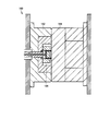
- the molding die according to the present invention is used for molding the fan described in any of the above. According to the molding die configured as described above, a resin fan can be manufactured.
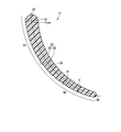
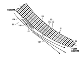
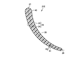
- FIG. 3 shows a blade cross section of the fan blade 21 when cut along a plane orthogonal to the central axis 101 which is the rotation axis of the cross-flow fan 100.
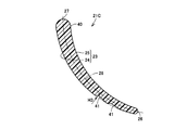
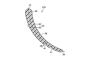
- the fan blade 21 has a blade cross-sectional shape in which a concave portion 41 is formed on the blade surface 23 when cut by a plane orthogonal to the central axis 101 as a rotation axis of the fan.
- the concave portion 41 is disposed at a position closer to the outer edge portion 26 than the inner edge portion 27 and extends from one end 31 to the other end 32 of the fan blade 21 in the fan rotation axis direction.
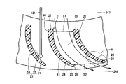
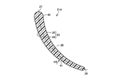
- the fan blade 21 has the same blade cross-sectional shape as the fan blade 21 in FIG. That is, the thick portion 40 where the thickness of the fan blade 21 is maximized is arranged to be biased toward the inner edge portion 27 of the inner edge portion 27 and the outer edge portion 26.
- a recess 41 is formed in the outer peripheral side region 52 of the negative pressure surface 24 of the fan blade 21.
- the blower 350 is provided for sucking indoor air into the housing 344 and sending out the air purified by the filter 341 into the room through the outlet 343.
- the blower 350 includes the centrifugal fan 10, a casing 352, and a drive motor 351.
- the casing 352 has a guide wall 352a.
- a suction part 353 and a blowing part 354 are formed in the casing 352.
Landscapes
- Engineering & Computer Science (AREA)
- Mechanical Engineering (AREA)
- General Engineering & Computer Science (AREA)
- Structures Of Non-Positive Displacement Pumps (AREA)
Abstract
Description
(貫流ファンの構造の説明)
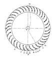
図1は、この発明の実施の形態1における貫流ファンを示す斜視図である。図2は、図1中の貫流ファンを構成する羽根車の1つを示す斜視図である。図3は、図1中のIII-III線上に沿った貫流ファンを示す断面図である。
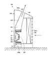
図5は、図1中の貫流ファンが用いられる空気調和機を示す断面図である。図5を参照して、空気調和機210は、室内に設置され、室内側熱交換器229が設けられる室内機220と、室外に設置され、室外側熱交換器および圧縮機が設けられる図示しない室外機とから構成されている。室内機220および室外機は、室内側熱交換器229と室外側熱交換器との間で冷媒ガスを循環させるための配管により接続されている。
続いて、本実施の形態における貫流ファン100によって奏される作用、効果を、貫流ファン100を図5から図7中の空気調和機に適用した場合を想定して説明する。
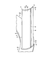
図12は、図2中のファンブレードを示す斜視図である。図13は、図12中のXIII-XIII線上に沿ったファンブレードを示す断面図である。図14は、図12中のXIV-XIV線上に沿ったファンブレードを示す断面図である。図13中には、ファンブレード21の一方端31側の断面が示され、図14中には、ファンブレード21の他方端32側の断面が示されている。
本実施の形態では、実施の形態1における貫流ファン100の変形例について説明を行なう。
本実施の形態では、まず、本発明におけるファンが適用される遠心ファンの構造について説明し、続いて、その遠心ファンが用いられる送風機および空気清浄機の構造について説明する。なお、本実施の形態における遠心ファンは、実施の形態1における貫流ファン100と比較して、部分的に同様の構造を備える。以下、重複する構造についてはその説明を繰り返さない。
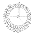
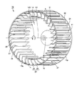
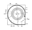
図22は、この発明の実施の形態3における遠心ファンを示す斜視図である。図22を参照して、本実施の形態における遠心ファン10は、複数のファンブレード21を有する。遠心ファン10は、全体として略円筒形の外観を有し、複数のファンブレード21は、その略円筒形の周面に配置されている。遠心ファン10は、樹脂により一体に形成されている。遠心ファン10は、図22中に示す仮想上の中心軸101を中心に、矢印103に示す方向に回転する。
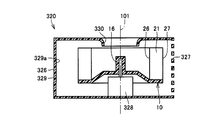
図23は、図22中の遠心ファンを用いた送風機を示す断面図である。図24は、図23中のXXIV-XXIV線上に沿った送風機を示す断面図である。図23および図24を参照して、送風機320は、外装ケーシング326内に、駆動モータ328と、遠心ファン10と、ケーシング329とを有する。
Claims (11)
- 内周側に配置される内縁部(27)と、外周側に配置される外縁部(26)とを有し、周方向に互いに間隔を隔てて設けられる複数の羽根部(21)を備え、
前記羽根部(21)には、前記内縁部(27)と前記外縁部(26)との間で延在する翼面(23)が形成され、
ファンの回転に伴って、前記翼面(23)上には前記内縁部(27)と前記外縁部(26)との間を流れる流体流れが発生し、
前記羽根部(21)は、ファンの回転軸に直交する平面により切断された場合に、前記翼面(23)に凹部(41)が形成される翼断面形状を有し、
前記凹部(41)は、前記内縁部(27)よりも前記外縁部(26)に近い位置に配置され、ファンの回転軸方向における前記羽根部(21)の一方端(31)から他方端(32)まで延びて形成される、ファン。 - 前記翼面(23)は、ファンの回転方向の側に配置される正圧面(25)と、前記正圧面(25)の裏側に配置される負圧面(24)とから構成され、
前記凹部(41)は、前記負圧面(24)に形成される、請求項1に記載のファン。 - 前記凹部(41)は、ファンの回転軸方向における前記羽根部(21)の一方端(31)から他方端(32)にかけて、その断面形状が変化するように形成される、請求項1に記載のファン。
- 前記凹部(41)は、ファンの回転軸方向における前記羽根部(21)の一方端(31)から他方端(32)にかけて、前記翼面(23)に開口する幅が変化するように形成される、請求項3に記載のファン。
- ファンの回転軸に直交する平面により切断された場合に、前記羽根部(21)の断面積は、ファンの回転軸方向における前記羽根部(21)の一方端(31)から他方端(32)に向かうほど大きくなり、
前記凹部(41)は、前記翼面(23)から凹む前記凹部(41)の断面積が前記羽根部(21)の一方端(31)側よりも他方端(32)側で大きくなるように形成される、請求項1に記載のファン。 - 複数の前記羽根部(21)は、前記羽根部(21)に形成される前記凹部(41)の形態が互いに異なる第1羽根部および第2羽根部を含む、請求項1に記載のファン。
- 周方向に配列された複数の前記羽根部(21)の内側に内側空間(247)が形成され、その外側に外側空間(246,248)が形成され、
ファンの回転軸方向から見た場合に、回転軸に対して一方の側の前記外側空間(246)から前記内側空間(247)に流体を取り込み、取り込んだ流体を回転軸に対して他方の側の前記外側空間(248)に送り出す貫流ファン(100)である、請求項1に記載のファン。 - 周方向に配列された複数の前記羽根部(21)の内側に内側空間(331)が形成され、その外側に外側空間(332)が形成され、
前記内側空間(331)から前記外側空間(332)に流体を送り出す遠心ファン(10)である、請求項1に記載のファン。 - 樹脂により形成される、請求項1に記載のファン。
- 請求項9に記載のファン(100,10)を成型するために用いられる、成型用金型。
- 請求項1に記載のファン(100,10)と、前記ファン(100,10)に連結され、複数の前記羽根部(21)を回転させる駆動モータ(351)とから構成される送風機(215,350)を備える、流体送り装置。
Priority Applications (1)
| Application Number | Priority Date | Filing Date | Title |
|---|---|---|---|
| US13/806,915 US9382912B2 (en) | 2010-06-28 | 2011-05-25 | Fan, molding die, and fluid feeder |
Applications Claiming Priority (2)
| Application Number | Priority Date | Filing Date | Title |
|---|---|---|---|
| JP2010-146051 | 2010-06-28 | ||
| JP2010146051A JP4993791B2 (ja) | 2010-06-28 | 2010-06-28 | ファン、成型用金型および流体送り装置 |
Publications (1)
| Publication Number | Publication Date |
|---|---|
| WO2012002080A1 true WO2012002080A1 (ja) | 2012-01-05 |
Family
ID=45357773
Family Applications (1)
| Application Number | Title | Priority Date | Filing Date |
|---|---|---|---|
| PCT/JP2011/061985 Ceased WO2012002080A1 (ja) | 2010-06-28 | 2011-05-25 | ファン、成型用金型および流体送り装置 |
Country Status (4)
| Country | Link |
|---|---|
| US (1) | US9382912B2 (ja) |
| JP (1) | JP4993791B2 (ja) |
| CN (2) | CN202251075U (ja) |
| WO (1) | WO2012002080A1 (ja) |
Families Citing this family (21)
| Publication number | Priority date | Publication date | Assignee | Title |
|---|---|---|---|---|
| JP4993791B2 (ja) | 2010-06-28 | 2012-08-08 | シャープ株式会社 | ファン、成型用金型および流体送り装置 |
| WO2014207908A1 (ja) * | 2013-06-28 | 2014-12-31 | 三菱電機株式会社 | 空気調和装置の室内機 |
| KR101626488B1 (ko) * | 2014-03-27 | 2016-06-01 | 엘지전자 주식회사 | 원심팬 |
| KR102210542B1 (ko) * | 2015-05-19 | 2021-02-02 | 엘지전자 주식회사 | 원심팬 |
| JP6634704B2 (ja) * | 2015-05-29 | 2020-01-22 | ダイキン工業株式会社 | クロスフローファン及びこれを用いた空気調和機 |
| CN106837863A (zh) * | 2017-03-29 | 2017-06-13 | 徐工集团工程机械有限公司 | 空调叶轮、工程车辆用空调以及工程车辆 |
| WO2019012578A1 (ja) * | 2017-07-10 | 2019-01-17 | 三菱電機株式会社 | 空気調和機の室内機 |
| CN107559234A (zh) * | 2017-09-05 | 2018-01-09 | 广东美的制冷设备有限公司 | 贯流风轮和具有其的空调室内机 |
| CN107956739B (zh) * | 2017-11-23 | 2024-04-26 | 广东美的制冷设备有限公司 | 贯流风轮及空调器 |
| FR3093760B1 (fr) * | 2019-03-15 | 2021-04-02 | Valeo Systemes Thermiques | Module de refroidissement pour véhicule automobile électrique à turbomachine tangentielle |
| GB2585707B (en) * | 2019-07-15 | 2021-08-11 | Dyson Technology Ltd | Variable radial inlet guide vane assembly |
| FR3100487B1 (fr) | 2019-09-10 | 2021-08-06 | Valeo Systemes Thermiques | Module de refroidissement pour véhicule automobile à turbomachine tangentielle |
| KR102782040B1 (ko) * | 2020-02-25 | 2025-03-13 | 엘지전자 주식회사 | 횡류팬 |
| CN111425462B (zh) * | 2020-03-31 | 2021-06-18 | 佛山市云米电器科技有限公司 | 一种出风阵列机构及应用其的出风设备 |
| JP7120360B1 (ja) * | 2021-03-01 | 2022-08-17 | 株式会社富士通ゼネラル | 送風機および室内機 |
| FR3121176B1 (fr) * | 2021-03-25 | 2023-03-17 | Valeo Systemes Thermiques | Module de refroidissement pour véhicule automobile électrique ou hybride |
| FR3121175B1 (fr) * | 2021-03-25 | 2023-03-17 | Valeo Systemes Thermiques | Module de refroidissement pour véhicule automobile électrique ou hybride |
| CN214660989U (zh) * | 2021-04-30 | 2021-11-09 | 中强光电股份有限公司 | 风扇结构 |
| CN113232864A (zh) * | 2021-06-05 | 2021-08-10 | 王会芬 | 一种农业种植用方便喷洒农药的植保无人机 |
| JPWO2023089658A1 (ja) * | 2021-11-16 | 2023-05-25 | ||
| CN114962286B (zh) * | 2022-06-14 | 2023-05-26 | 江西昊仁电力设备有限公司 | 一种用于干式变压器的横流冷却风机 |
Citations (5)
| Publication number | Priority date | Publication date | Assignee | Title |
|---|---|---|---|---|
| JPH074388A (ja) * | 1993-06-15 | 1995-01-10 | Matsushita Refrig Co Ltd | 遠心送風機の羽根車 |
| JPH07310696A (ja) * | 1994-05-13 | 1995-11-28 | Daikin Ind Ltd | 送風機 |
| JP2007010259A (ja) * | 2005-07-01 | 2007-01-18 | Hitachi Appliances Inc | 空気調和機 |
| JP2010106853A (ja) * | 2010-02-16 | 2010-05-13 | Sharp Corp | 貫流ファン、送風機および羽根車の成形機 |
| JP2010174852A (ja) * | 2009-02-02 | 2010-08-12 | Daikin Ind Ltd | クロスフローファンおよびそれを備えた空気調和機 |
Family Cites Families (13)
| Publication number | Priority date | Publication date | Assignee | Title |
|---|---|---|---|---|
| US3536416A (en) * | 1968-05-14 | 1970-10-27 | Dov Z Glucksman | Squirrel-cage rotor for fluid moving devices |
| JPH01318798A (ja) | 1988-06-17 | 1989-12-25 | Taiheiyo Kogyo Kk | クロスフローファンの羽根車 |
| KR920009858B1 (ko) * | 1989-03-20 | 1992-11-02 | 산코우 고오세이 쥬시 가부시끼가이샤 | 크로스 플로우 팬(cross flow FAN)의 일체성형법 및 일체성형 가능한 크로스 플로우 팬 |
| JPH0544686A (ja) | 1991-08-12 | 1993-02-23 | Daikin Ind Ltd | 横流フアン |
| US5169290A (en) * | 1991-11-07 | 1992-12-08 | Carrier Corporation | Blade for centrifugal flow fan |
| WO2005003566A1 (ja) * | 2003-06-23 | 2005-01-13 | Matsushita Electric Industrial Co., Ltd. | 遠心ファン及びそれを用いた装置 |
| JP3969354B2 (ja) | 2003-06-23 | 2007-09-05 | 松下電器産業株式会社 | 遠心ファンおよびその用途 |
| JP2006077723A (ja) * | 2004-09-13 | 2006-03-23 | Matsushita Electric Ind Co Ltd | 多翼ファン |
| CN100519136C (zh) | 2005-03-29 | 2009-07-29 | 三菱电机株式会社 | 成形模具、风扇制造方法 |
| US7494325B2 (en) * | 2005-05-18 | 2009-02-24 | Hartzell Fan, Inc. | Fan blade with ridges |
| JP3901200B2 (ja) * | 2005-08-05 | 2007-04-04 | ダイキン工業株式会社 | 樹脂製クロスフローファン及びその製造方法 |
| US8225623B2 (en) * | 2007-03-14 | 2012-07-24 | Mitsubishi Electric Corporation | Centrifugal fan, air conditioner |
| JP4993791B2 (ja) | 2010-06-28 | 2012-08-08 | シャープ株式会社 | ファン、成型用金型および流体送り装置 |
-
2010
- 2010-06-28 JP JP2010146051A patent/JP4993791B2/ja active Active
-
2011
- 2011-05-25 WO PCT/JP2011/061985 patent/WO2012002080A1/ja not_active Ceased
- 2011-05-25 US US13/806,915 patent/US9382912B2/en active Active
- 2011-06-21 CN CN2011202132327U patent/CN202251075U/zh not_active Expired - Fee Related
- 2011-06-21 CN CN201110170099.6A patent/CN102297155B/zh active Active
Patent Citations (5)
| Publication number | Priority date | Publication date | Assignee | Title |
|---|---|---|---|---|
| JPH074388A (ja) * | 1993-06-15 | 1995-01-10 | Matsushita Refrig Co Ltd | 遠心送風機の羽根車 |
| JPH07310696A (ja) * | 1994-05-13 | 1995-11-28 | Daikin Ind Ltd | 送風機 |
| JP2007010259A (ja) * | 2005-07-01 | 2007-01-18 | Hitachi Appliances Inc | 空気調和機 |
| JP2010174852A (ja) * | 2009-02-02 | 2010-08-12 | Daikin Ind Ltd | クロスフローファンおよびそれを備えた空気調和機 |
| JP2010106853A (ja) * | 2010-02-16 | 2010-05-13 | Sharp Corp | 貫流ファン、送風機および羽根車の成形機 |
Also Published As
| Publication number | Publication date |
|---|---|
| US20130101408A1 (en) | 2013-04-25 |
| US9382912B2 (en) | 2016-07-05 |
| CN202251075U (zh) | 2012-05-30 |
| JP4993791B2 (ja) | 2012-08-08 |
| CN102297155B (zh) | 2015-11-25 |
| CN102297155A (zh) | 2011-12-28 |
| JP2012007585A (ja) | 2012-01-12 |
Similar Documents
| Publication | Publication Date | Title |
|---|---|---|
| JP4993791B2 (ja) | ファン、成型用金型および流体送り装置 | |
| JP4993792B2 (ja) | ファン、成型用金型および流体送り装置 | |
| US9885364B2 (en) | Fan, molding die, and fluid feeder | |
| JP4831707B2 (ja) | 貫流ファン、成型用金型および流体送り装置 | |
| JP5203478B2 (ja) | 貫流ファン、成型用金型および流体送り装置 | |
| JP4761324B2 (ja) | 貫流ファン、成型用金型および流体送り装置 | |
| JP5744209B2 (ja) | 空気調和機 | |
| JP5179638B2 (ja) | ファン、成型用金型および流体送り装置 | |
| JP5893385B2 (ja) | ファン、成型用金型および流体送り装置 | |
| JP4906010B2 (ja) | ファン、成型用金型および流体送り装置 | |
| JP4775867B1 (ja) | ファン、成型用金型および流体送り装置 | |
| JP4906011B2 (ja) | ファン、成型用金型および流体送り装置 |
Legal Events
| Date | Code | Title | Description |
|---|---|---|---|
| 121 | Ep: the epo has been informed by wipo that ep was designated in this application |
Ref document number: 11800549 Country of ref document: EP Kind code of ref document: A1 |
|
| WWE | Wipo information: entry into national phase |
Ref document number: 13806915 Country of ref document: US |
|
| NENP | Non-entry into the national phase |
Ref country code: DE |
|
| WWE | Wipo information: entry into national phase |
Ref document number: 1201006763 Country of ref document: TH |
|
| 122 | Ep: pct application non-entry in european phase |
Ref document number: 11800549 Country of ref document: EP Kind code of ref document: A1 |