WO2012002003A1 - 医療用軟質容器及びこれを用いた栄養供給システム - Google Patents
医療用軟質容器及びこれを用いた栄養供給システム Download PDFInfo
- Publication number
- WO2012002003A1 WO2012002003A1 PCT/JP2011/054948 JP2011054948W WO2012002003A1 WO 2012002003 A1 WO2012002003 A1 WO 2012002003A1 JP 2011054948 W JP2011054948 W JP 2011054948W WO 2012002003 A1 WO2012002003 A1 WO 2012002003A1
- Authority
- WO
- WIPO (PCT)
- Prior art keywords
- opening
- closing operation
- soft
- flexible bag
- bag member
- Prior art date
- Legal status (The legal status is an assumption and is not a legal conclusion. Google has not performed a legal analysis and makes no representation as to the accuracy of the status listed.)
- Ceased
Links
Images











Classifications
-
- A—HUMAN NECESSITIES
- A61—MEDICAL OR VETERINARY SCIENCE; HYGIENE
- A61J—CONTAINERS SPECIALLY ADAPTED FOR MEDICAL OR PHARMACEUTICAL PURPOSES; DEVICES OR METHODS SPECIALLY ADAPTED FOR BRINGING PHARMACEUTICAL PRODUCTS INTO PARTICULAR PHYSICAL OR ADMINISTERING FORMS; DEVICES FOR ADMINISTERING FOOD OR MEDICINES ORALLY; BABY COMFORTERS; DEVICES FOR RECEIVING SPITTLE
- A61J1/00—Containers specially adapted for medical or pharmaceutical purposes
- A61J1/05—Containers specially adapted for medical or pharmaceutical purposes for collecting, storing or administering blood, plasma or medical fluids ; Infusion or perfusion containers
- A61J1/10—Bag-type containers
-
- A—HUMAN NECESSITIES
- A61—MEDICAL OR VETERINARY SCIENCE; HYGIENE
- A61J—CONTAINERS SPECIALLY ADAPTED FOR MEDICAL OR PHARMACEUTICAL PURPOSES; DEVICES OR METHODS SPECIALLY ADAPTED FOR BRINGING PHARMACEUTICAL PRODUCTS INTO PARTICULAR PHYSICAL OR ADMINISTERING FORMS; DEVICES FOR ADMINISTERING FOOD OR MEDICINES ORALLY; BABY COMFORTERS; DEVICES FOR RECEIVING SPITTLE
- A61J1/00—Containers specially adapted for medical or pharmaceutical purposes
- A61J1/14—Details; Accessories therefor
- A61J1/1462—Containers with provisions for hanging, e.g. integral adaptations of the container
-
- A—HUMAN NECESSITIES
- A61—MEDICAL OR VETERINARY SCIENCE; HYGIENE
- A61J—CONTAINERS SPECIALLY ADAPTED FOR MEDICAL OR PHARMACEUTICAL PURPOSES; DEVICES OR METHODS SPECIALLY ADAPTED FOR BRINGING PHARMACEUTICAL PRODUCTS INTO PARTICULAR PHYSICAL OR ADMINISTERING FORMS; DEVICES FOR ADMINISTERING FOOD OR MEDICINES ORALLY; BABY COMFORTERS; DEVICES FOR RECEIVING SPITTLE
- A61J1/00—Containers specially adapted for medical or pharmaceutical purposes
- A61J1/14—Details; Accessories therefor
- A61J1/1493—Containers with shape retaining means, e.g. to support the structure of the container during emptying or filling
-
- A—HUMAN NECESSITIES
- A61—MEDICAL OR VETERINARY SCIENCE; HYGIENE
- A61J—CONTAINERS SPECIALLY ADAPTED FOR MEDICAL OR PHARMACEUTICAL PURPOSES; DEVICES OR METHODS SPECIALLY ADAPTED FOR BRINGING PHARMACEUTICAL PRODUCTS INTO PARTICULAR PHYSICAL OR ADMINISTERING FORMS; DEVICES FOR ADMINISTERING FOOD OR MEDICINES ORALLY; BABY COMFORTERS; DEVICES FOR RECEIVING SPITTLE
- A61J15/00—Feeding-tubes for therapeutic purposes
-
- B—PERFORMING OPERATIONS; TRANSPORTING
- B65—CONVEYING; PACKING; STORING; HANDLING THIN OR FILAMENTARY MATERIAL
- B65D—CONTAINERS FOR STORAGE OR TRANSPORT OF ARTICLES OR MATERIALS, e.g. BAGS, BARRELS, BOTTLES, BOXES, CANS, CARTONS, CRATES, DRUMS, JARS, TANKS, HOPPERS, FORWARDING CONTAINERS; ACCESSORIES, CLOSURES, OR FITTINGS THEREFOR; PACKAGING ELEMENTS; PACKAGES
- B65D33/00—Details of, or accessories for, sacks or bags
-
- B—PERFORMING OPERATIONS; TRANSPORTING
- B65—CONVEYING; PACKING; STORING; HANDLING THIN OR FILAMENTARY MATERIAL
- B65D—CONTAINERS FOR STORAGE OR TRANSPORT OF ARTICLES OR MATERIALS, e.g. BAGS, BARRELS, BOTTLES, BOXES, CANS, CARTONS, CRATES, DRUMS, JARS, TANKS, HOPPERS, FORWARDING CONTAINERS; ACCESSORIES, CLOSURES, OR FITTINGS THEREFOR; PACKAGING ELEMENTS; PACKAGES
- B65D33/00—Details of, or accessories for, sacks or bags
- B65D33/16—End- or aperture-closing arrangements or devices
- B65D33/18—End- or aperture-closing arrangements or devices using adhesive applied to integral parts, e.g. to flaps
- B65D33/22—End- or aperture-closing arrangements or devices using adhesive applied to integral parts, e.g. to flaps using heat-activatable adhesive
-
- A—HUMAN NECESSITIES
- A61—MEDICAL OR VETERINARY SCIENCE; HYGIENE
- A61J—CONTAINERS SPECIALLY ADAPTED FOR MEDICAL OR PHARMACEUTICAL PURPOSES; DEVICES OR METHODS SPECIALLY ADAPTED FOR BRINGING PHARMACEUTICAL PRODUCTS INTO PARTICULAR PHYSICAL OR ADMINISTERING FORMS; DEVICES FOR ADMINISTERING FOOD OR MEDICINES ORALLY; BABY COMFORTERS; DEVICES FOR RECEIVING SPITTLE
- A61J1/00—Containers specially adapted for medical or pharmaceutical purposes
- A61J1/14—Details; Accessories therefor
- A61J1/1475—Inlet or outlet ports
-
- A—HUMAN NECESSITIES
- A61—MEDICAL OR VETERINARY SCIENCE; HYGIENE
- A61J—CONTAINERS SPECIALLY ADAPTED FOR MEDICAL OR PHARMACEUTICAL PURPOSES; DEVICES OR METHODS SPECIALLY ADAPTED FOR BRINGING PHARMACEUTICAL PRODUCTS INTO PARTICULAR PHYSICAL OR ADMINISTERING FORMS; DEVICES FOR ADMINISTERING FOOD OR MEDICINES ORALLY; BABY COMFORTERS; DEVICES FOR RECEIVING SPITTLE
- A61J2200/00—General characteristics or adaptations
- A61J2200/70—Device provided with specific sensor or indicating means
- A61J2200/76—Device provided with specific sensor or indicating means for fluid level
Definitions
- the present invention relates to a medical soft container and a nutrient supply system using the same.
- Enteral nutrition or parenteral nutrition is known as a method for administering nutrition and drugs to patients without oral administration.
- a liquid such as a nutrient, liquid food, or drug is administered through a tube passed from the patient's nasal cavity to the stomach or duodenum.
- a liquid generally referred to as “infusion”
- nutritional components such as glucose and / or drug components is administered via an infusion circuit inserted into a patient's vein.
- FIG. 17 is a front view showing a schematic configuration of an example of a conventional medical soft container 900.
- FIG. 18 is a diagram illustrating the opening of the medical soft container 900 shown in FIG.
- FIG. 19 is a view showing a state in which the opening 922 is opened by gripping with FIG. 19, and
- FIG. 19 is a view showing a state in which a liquid material is poured into the medical soft container 900 shown in FIG.
- the soft medical container 900 includes a storage portion 921 for storing a liquid material and a discharge port 930 in which a through hole for taking out the liquid material stored in the storage portion 921 is formed.
- the accommodating part 921 is a bag-like product formed by superposing two flexible sheets and joining their outer peripheral edges to each other by heat sealing (thermal bonding).
- the discharge port 930 is made of a resin material that is relatively harder than the above-described sheet constituting the housing portion 921.
- the injection of the liquid material into the empty medical soft container 900 is performed as follows. First, with the notch 928 as a starting point, the upper portion of the opening 922 is cut along the cut line 929 to open, and the engagement of the zip 923 is released. Next, as shown in FIG. 18, the opening 922 is opened while holding the outer edge of the opening 922 with one hand. Next, as shown in FIG. 19, the other hand (not shown) holds a container 998 containing a liquid substance such as a medicine or a nutrient, and injects the liquid substance from the opening 922 into the accommodating portion 921. .
- the outer edge of the opening 922 is held with one hand from the start to the end of the liquid injection operation to open the opening 922.
- the soft medical container 900 must be held.
- the injection amount of the liquid material increases, the weight of the medical soft container 900 gradually increases.
- the soft medical container 900 is made of a flexible material including the opening 922, the opening 922 is easily deformed when a large gripping force is applied. Therefore, there is a possibility that the soft medical container 900 may be dropped or the opening 922 cannot be sufficiently opened to spill liquid.
- the operation of injecting the liquid material into the conventional medical soft container 900 has a great mental and physical burden on the operator.
- the medical soft container with a member that can stably hold the soft medical container with the opening thereof opened.
- the sheet constituting the soft medical container generally has low mechanical strength, it is desirable that when such a member is provided, stress concentration does not occur due to the opening / closing operation of the opening and the weight of the injected liquid material. It is. Moreover, it must be avoided that the quality of the medical soft container is lowered by providing such a member.
- the soft medical container of the present invention is provided with a flexible bag member having an opening that can be opened and closed at the upper end, and a lower end of the flexible bag member. And a pair of opening / closing operation portions provided on the flexible bag member so that an insertion path into which a finger can be inserted is formed. At least one of the upper and lower end portions of the pair of opening / closing operation portions is fixed to the outer surface of the flexible bag member by heat sealing.
- the heating region when the at least one end is fixed by heat sealing includes all of the end edges of the at least one end, and the outer peripheral edge of the heating region and the side edges on both sides of the opening / closing operation unit The outer peripheral edge is inclined with respect to the longitudinal direction of the opening / closing operation part at the intersection with the edge.
- the nutrient supply system of the present invention includes the above-described soft medical container of the present invention.
- the medical soft container by inserting a finger into an insertion path formed by a pair of opening / closing operation portions provided on the flexible bag member, the medical soft container can be stably maintained with the opening opened. Can be held.
- the heating region when the end of the opening / closing operation part is fixed by heat sealing includes all of the end edges of the end parts, the end edges adhere to the soft resin sheet. Accordingly, the provision of the opening / closing operation unit does not reduce the feeling of touch and the appearance, and the deterioration of the quality of the medical soft container can be prevented.
- the outer peripheral edge is inclined with respect to the longitudinal direction of the opening / closing operation part at the intersection of the outer peripheral edge of the heating region and the side edge of the opening / closing operation part. Therefore, when an external force is applied to the central portion of the opening / closing operation portion so as to peel the central portion from the flexible bag member, it is possible to prevent a large stress concentration from occurring at the intersection.
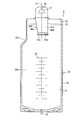
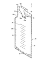
- FIG. 1 is a perspective view of a soft medical container according to Embodiment 1 of the present invention.
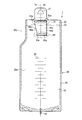
- FIG. 2A is a front view of the soft medical container according to Embodiment 1 of the present invention.
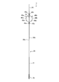
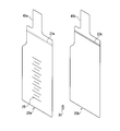
- FIG. 2B is a right side view of the soft medical container according to Embodiment 1 of the present invention.
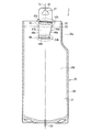
- FIG. 2C is a rear view of the soft medical container according to Embodiment 1 of the present invention.
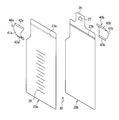
- FIG. 3 is an exploded perspective view of the soft medical container according to Embodiment 1 of the present invention.
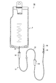
- FIG. 4 is a diagram showing a schematic configuration of an enteral nutrition supply system including a soft medical container according to Embodiment 1 of the present invention.
- FIG. 4 is a diagram showing a schematic configuration of an enteral nutrition supply system including a soft medical container according to Embodiment 1 of the present invention.
- FIG. 5 is a perspective view showing a state in which the soft medical container according to Embodiment 1 of the present invention is held with one hand and the opening is opened.
- FIG. 6 is a perspective view showing a state in which the soft medical container according to Embodiment 1 of the present invention is held with one hand and a liquid material is poured into the opening.
- 7A is an enlarged view of a portion 7A of FIG. 2A showing the upper end portion of the front-side opening / closing operation unit and the heating area by heat sealing in Embodiment 1 of the present invention
- FIG. 7B is the back side in Embodiment 1 of the present invention. It is the enlarged view of the part 7B of FIG.
- FIG. 8A is an enlarged view of a portion 8A of FIG. 2A showing a lower end portion of the front-side opening / closing operation unit and a heating area by heat sealing in Embodiment 1 of the present invention
- FIG. 8B is a back side in Embodiment 1 of the present invention. It is the enlarged view of the part 8B of FIG. 2C which showed the upper end part of the opening / closing operation part of FIG. 2, and the heating area
- FIG. 8A is an enlarged view of a portion 8A of FIG. 2A showing a lower end portion of the front-side opening / closing operation unit and a heating area by heat sealing in Embodiment 1 of the present invention
- FIG. 8B is a back side in Embodiment 1 of the present invention. It is the enlarged view of the part 8B of FIG. 2C which showed the upper end part of the opening / closing operation part of FIG. 2, and the heating area
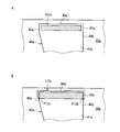
- FIG. 9A is an enlarged view showing a heating region according to a comparative example using the upper end portion of the front side opening / closing operation unit and heat sealing
- FIG. 9B relates to another comparative example using the upper end portion of the front side opening / closing operation unit and heat sealing. It is the enlarged view which showed the heating area
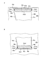
- FIG. 10A is an enlarged view showing an upper end portion of the front-side opening / closing operation portion and a heating region by heat sealing in Embodiment 2 of the present invention
- FIG. 10B is a lower end portion of the front-side opening / closing operation portion in Embodiment 2 of the present invention. It is the enlarged view which showed the heating area
- FIG. 10A is an enlarged view showing an upper end portion of the front-side opening / closing operation portion and a heating region by heat sealing in Embodiment 2 of the present invention
- FIG. 10B is a lower end portion of the front-side opening / closing operation portion in Embodiment
- FIG. 11 is a perspective view of a soft medical container according to Embodiment 3 of the present invention.
- FIG. 12A is a front view of a soft medical container according to Embodiment 3 of the present invention.
- FIG. 12B is a right side view of the soft medical container according to Embodiment 3 of the present invention.
- FIG. 13 is an enlarged view showing an upper end portion of the front-side opening / closing operation unit and a heating region by heat sealing in Embodiment 3 of the present invention.
- FIG. 14 is a perspective view of a soft medical container according to Embodiment 4 of the present invention.
- FIG. 15A is a front view of a soft medical container according to Embodiment 4 of the present invention.
- FIG. 15B is a right side view of the soft medical container according to Embodiment 4 of the present invention.
- FIG. 16 is an exploded perspective view of a soft medical container according to Embodiment 4 of the present invention.
- FIG. 17 is a front view showing a schematic configuration of an example of a conventional medical soft container.
- FIG. 18 is a diagram showing a state where the opening of the soft medical container shown in FIG. 17 is held with one hand and the opening is opened.
- FIG. 19 is a view showing a state in which a liquid material is poured into the medical soft container shown in FIG.
- At least one of the end portions of the opening / closing operation portion fixed to the flexible bag member by heat sealing satisfies the following two conditions.
- the heating region when the end portion is fixed by heat sealing includes all of the end edge of the end portion (hereinafter referred to as “first condition”).
- the heating area “includes” all of the end edges means that all of the end edges exist in the heating area (including a case where a part of the end edges are located on the outer periphery of the heating area). means. Preferably, it means that all of the end edges are present inside the outer peripheral edge without contacting the outer peripheral edge of the heating region.
- the outer peripheral edge is inclined with respect to the longitudinal direction of the opening / closing operation part (hereinafter referred to as “second condition”).
- second condition the outer peripheral edge is “inclined” with respect to the longitudinal direction of the opening / closing operation part, even though the tangential direction of the outer peripheral edge at the intersection point is parallel to the longitudinal direction of the opening / closing operation part.
- the longitudinal direction of the opening / closing operation part means a direction connecting the upper and lower ends fixed to the flexible bag member of the opening / closing operation part.
- the heating region has a substantially arc and a line segment connecting both ends of the substantially arc, and the substantially arc intersects the side edge of the opening / closing operation unit.
- the intersection between the outer peripheral edge of the heating region and the side edge of the opening / closing operation part is applied to the central part of the opening / closing operation part, regardless of the external force acting in any direction that tears the central part off the flexible bag member. Needless to say, it is possible to prevent a large stress concentration from occurring in other locations.
- the heating region may have a substantially trapezoidal shape, and a hypotenuse of the substantially trapezoidal shape may intersect the side edge of the opening / closing operation unit.
- the pair of opening / closing operation portions may be created as a member separate from the soft resin sheet constituting the flexible bag member.
- the upper end portion and the lower end portion of each of the pair of opening / closing operation portions are fixed to the outer surface of the flexible bag member by heat sealing.
- the upper end portions of the pair of opening / closing operation portions are fixed to the outer surface of the flexible bag member by heat sealing heated in a heating region that satisfies the first condition and the second condition. Preferably it is. Thereby, it is possible to prevent a large stress concentration from occurring at the upper end where a large force is often applied.
- each of the pair of opening / closing operation units may be integrally formed with the soft resin sheet constituting the flexible bag member.
- the lower end of each of the pair of opening / closing operation portions is fixed to the outer surface of the flexible bag member by heat sealing.
- the upper end of the opening / closing operation part where a large force is often applied, is formed integrally with the soft resin sheet, so that the connection strength between the opening / closing operation part and the soft resin sheet at the end is improved. To do.
- FIG. 1 is a perspective view of a soft medical container 1 according to Embodiment 1 of the present invention.
- 2A is a front view of the medical soft container 1
- FIG. 2B is a right side view of the medical soft container 1
- FIG. 2C is a rear view of the medical soft container 1.
- FIG. 3 is an exploded perspective view of the medical soft container 1.
- the “upper side” upper side of the paper in FIG. 1) and “lower side” (lower side of the paper in FIG. 1) of the soft medical container 1 are defined in accordance with the actual use state.
- the left-right direction when the medical soft container 1 is viewed from the front side (see FIG. 2A) or from the back side (see FIG. 2C) is referred to as a “width direction”.
- the soft medical container 1 of this embodiment is fixed to a flat bag-like flexible bag member 20 and a lower end of the flexible bag member 20. And a discharge port 30.
- the flexible bag member 20 includes a storage portion 21 for storing a liquid material, and an opening 22 communicating with the storage portion 21.
- the opening 22 crosses the opening 22 in the width direction and is a zip 23 (an engaging portion that can be freely opened and closed, which can be opened and closed reversibly. This is also called “chuck seal”. ) Is provided.
- the flexible bag member 20 includes a hanging portion 26 above the opening 22.
- the suspension part 26 is formed with a suspension hole 27 that is used when the medical soft container 1 is suspended on a stand or the like.
- the vertical axis passing through the suspension hole 27 and the discharge port 30 is referred to as the central axis 1a of the medical soft container 1.
- the central shaft 1a bisects a portion of the flexible bag member 20 below a notch 20c, which will be described later, in the width direction.
- the flexible bag member 20 is formed by, for example, stacking two soft resin sheets 20a and 20b and heat-sealing (thermally bonding) their outer peripheral edges to each other.
- Reference numeral 24 in FIGS. 1 and 2A to 2C indicates a heat seal area of the two soft resin sheets 20a and 20b.
- reference numerals 23 a and 23 b are zip tapes constituting the zip 23.
- the zip tapes 23a and 23b are fixed to the mutually opposing surfaces (inner surfaces) of the soft resin sheets 20a and 20b by a known method such as heat sealing.
- poured in the flexible bag member 20 is provided in the surface on the opposite side to the soft resin sheet 20b of the soft resin sheet 20a.
- the scale 25 is provided along the central axis 1a.
- the hanging part 26 described above is provided on the soft resin sheet 20b.
- the outer surface of the soft resin sheet 20a provided with the scale 25 (the surface that does not face the soft resin sheet 20b) is referred to as the “front surface” of the medical soft container 1, and the outer surface (soft resin sheet) of the soft resin sheet 20b.
- the surface that does not face 20a is referred to as the “back surface” of the medical soft container 1.
- the discharge port 30 is, for example, a tubular body having a through hole formed at the center thereof.
- the discharge port 30 is fixed to the flexible bag member 20 by being sandwiched between the soft resin sheets 20a and 20b.
- the through hole of the discharge port 30 communicates the inside and outside of the flexible bag member 20.
- the discharge port 30 can be integrated with the soft resin sheets 20a and 20b by heat-sealing the soft resin sheets 20a and 20b in the heat seal region 24 in a state of being disposed between the soft resin sheets 20a and 20b. .
- Open / close operation portions 40a and 40b are fixed to the surfaces of the soft resin sheets 20a and 20b opposite to each other (that is, the outer surfaces), respectively.
- the opening / closing operation units 40a and 40b are arranged along the central axis 1a.
- the opening / closing operation units 40a and 40b are made of a sheet-like material made of, for example, a soft resin.
- the upper end portions 42a and 42b and the lower end portions 43a and 43b of the opening / closing operation portions 40a and 40b are heat sealed to the outer surfaces of the soft resin sheets 20a and 20b, respectively.
- the soft medical container 1 is asymmetrical with respect to the central axis 1a when viewed from the front side or the back side. That is, as shown in FIG. 2A, when the soft medical container 1 is viewed from the front side, the left end of the upper portion of the flexible bag member 20 is cut out to form a cutout 20c.
- the side edge 46a on the side close to the notch 20c among the side edges 46a, 46b on both sides in the width direction (that is, the left-right direction) of the opening / closing operation units 40a, 40b is inclined with respect to the central axis 1a.
- the side edge 46b far from the notch 20c is substantially parallel to the central axis 1a.
- the soft medical container 1 can configure a nutrient supply system 90 by connecting an infusion set 91 to the discharge port 30 thereof, for example.
- the infusion set 91 has a flexible tube 92 whose one end is connected to the discharge port 30, a drip tube 93 and a flow rate regulator 94 provided on the flexible tube 92, and the other end of the flexible tube 92.
- a connector 95 provided on the connector 95, a connector cover 96 that covers the connector 95, and the like.
- the drip tube 93 visualizes the flow rate of the liquid material flowing through the infusion set 91.
- the flow rate regulator 94 presses the flexible tube 92 to change the flow path cross-sectional area thereof, thereby enabling the flow rate adjustment of the liquid material flowing through the infusion set 91.
- the connector 95 is connected to a tube (not shown) inserted into the patient's nasal cavity or vein.
- the nutrient supply system of the present invention is not limited to the configuration shown in FIG. 4.
- the nutrient supply system can be configured by combining any conventionally known infusion set with the medical soft container 1 of the present embodiment. It may be configured.
- the flow rate regulator 94 is operated to crush the flexible tube 92 and close the flow path.
- the left thumb is inserted into the insertion path 45a of the opening / closing operation unit 40a, and the other finger (index finger in FIG. 5) is inserted into the insertion path 45b of the opening / closing operation unit 40b.
- the opening 22 can be freely opened and closed by bringing the thumb and index finger into and out of the insertion paths 45a and 45b with the thumb and index finger inserted and separated.
- the liquid in the cup 98 held by the right hand (not shown) while holding the soft medical container 1 with the left hand with the opening 22 opened (for example, infusion) Is poured into the opening 22.
- the soft medical container 1 Since the thumb and forefinger are inserted into the insertion paths 45a and 45b, the soft medical container 1 can be stably held with the opening 22 being greatly opened. Therefore, the possibility that the soft medical container 1 is dropped or the opening 22 cannot be sufficiently opened and the liquid material is spilled is reduced. Therefore, the mental and physical burden on the operator in the operation of injecting the liquid material into the medical soft container 1 is reduced.
- the front of the medical soft container 1 faces the operator as shown in FIG. 6, so that the scale 25 attached to the front can be easily seen. Further, the scale 25 is not hidden by the left hand or the like. Since the opening / closing operation parts 40a, 40b and the scale 25 are provided along the central axis 1a (see FIGS. 2A and 2C), the soft medical container 1 held by the opening / closing operation parts 40a, 40b has the central axis 1a is held so as to be substantially parallel to the direction of gravity, and the injection amount can be accurately measured with the scale 25.
- the zip 23 is engaged to close the opening 22.
- the medical soft container 1 filled with the liquid material is suspended on a stand or the like by using the suspension hole 27 of the suspension part 26 disposed above the opening 22.
- the medical soft container 1 is suspended so that its central axis 1a is substantially parallel to the direction of gravity and the discharge port 30 is at the lowest position.
- the liquid substance in the medical soft container 1 can be administered to a patient. Since the discharge port 30 is positioned at the lowest position, the liquid material in the medical soft container 1 flows out without any residue.
- the attachment position of the opening / closing operation portions 40a and 40b with respect to the flexible bag member 20 is not particularly limited as long as the medical flexible container 1 can be held with one hand while the opening 22 is opened. In general, it is preferable to attach the opening / closing operation portions 40a and 40b so that insertion paths 45a and 45b penetrating in the left-right direction are formed in the vicinity of the upper end of the opening portion 22. In the case where the opening 22 is provided with the zip 23, the zip 23 may be opened while a finger is put in the insertion paths 45a and 45b.
- the opening / closing operation portions 40a, 40b are attached to the opening portion 22 so that the upper end portions 42a, 42b and the lower end portions 43a, 43b of the opening / closing operation portions 40a, 40b sandwich the zip 23 up and down as in this embodiment. It is preferable.
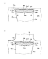
- FIG. 7A is an enlarged view of a portion 7A of FIG. 2A showing an upper end portion 42a of the front-side opening / closing operation portion 40a and a heating area 52a by heat sealing
- FIG. 7B is an upper end portion 42b of the rear-side opening / closing operation portion 40b and heat. It is the enlarged view of the part 7B of FIG. 2C which showed the heating area
- the heating regions 52a and 52b surrounded by the solid lines shown in FIGS. 7A and 7B are heating regions when the upper end portions 42a and 42b are fused to the soft resin sheets 20a and 20b by heat sealing. Heat sealing is generally performed by pressing a heated mold against a member to be fused. Accordingly, the heating regions 52a and 52b are also mold marks formed by a mold pressed when performing heat sealing.
- the upper end portions 42a and 42b of the opening / closing operation portions 40a and 40b are fixed to the soft resin sheets 20a and 20b in the overlapping region with the heating regions 52a and 52b.
- the outer shape of the heating regions 52a and 52b has approximately arcs 52a1 and 52b1 and line segments 52a2 and 52b2 connecting both ends of the approximately arcs 52a1 and 52b1.
- the substantially circular arcs 52a1 and 52b1 are disposed closer to the central portions 41a and 41b of the opening / closing operation units 40a and 40b than the line segments 52a2 and 52b2.
- the heating regions 52a and 52b include all of the end edges 47a and 47b on the opposite side of the central portions 41a and 41b of the opening / closing operation portions 40a and 40b (first condition). Further, at the intersections P12a and P12b between the outer peripheral edges (substantially arcs 52a1 and 52b1 in the present embodiment) of the heating regions 52a and 52b and the side edges 46a and 46b on both sides in the width direction of the opening / closing operation units 40a and 40b.
- the outer peripheral edges (substantially arcs 52a1, 52b1) of 52a, 52b are inclined with respect to the longitudinal direction of the opening / closing operation units 40a, 40b (in the direction of the central axis 1a in this embodiment) (second condition).
- FIG. 8A is an enlarged view of a portion 8A of FIG. 2A showing a lower end portion 43a of the front side opening / closing operation unit 40a and a heating region 53a by heat sealing
- FIG. 8B is a lower end portion 43b of the rear side opening / closing operation unit 40b and heat. It is the enlarged view of the part 8B of FIG. 2C which showed the heating area
- the lower end portions 43a and 43b of the opening / closing operation units 40a and 40b are fixed to the soft resin sheets 20a and 20b in the overlapping region with the heating regions 52a and 52b.
- the outer shapes of the heating regions 53a and 53b include approximately arcs 53a1 and 53b1 and line segments 53a2 and 53b2 connecting both ends of the approximately arcs 53a1 and 53b1.
- the substantially circular arcs 53a1 and 53b1 are arranged closer to the central portions 41a and 41b of the opening / closing operation portions 40a and 40b than the line segments 53a2 and 53b2.
- the heating regions 53a and 53b include all of the end edges 48a and 48b on the opposite side of the central portions 41a and 41b of the opening / closing operation portions 40a and 40b (first condition). Further, at the intersections P13a and P13b between the outer peripheral edges (substantially arcs 53a1 and 53b1 in the present embodiment) of the heating regions 53a and 53b and the side edges 46a and 46b on both sides in the width direction of the opening / closing operation units 40a and 40b.
- the outer peripheral edges (substantially arcs 52a1, 52b1) of 52a, 52b are inclined with respect to the longitudinal direction of the opening / closing operation units 40a, 40b (in the direction of the central axis 1a in this embodiment) (second condition).
- FIGS. 9A and 9B an example in which the upper end 42a of the opening / closing operation unit 40a is fixed to the soft resin sheet 20a in a heating region different from the present invention by heat sealing is shown in FIGS. 9A and 9B.
- the heating region 102a shown in FIG. 9A has a substantially rectangular shape arranged on the inner side of the terminal edge 48a and the side end edges 46a and 46b of the upper end part 42a of the opening / closing operation part 40a. Therefore, unlike the heating region of the present embodiment, the heating region 102a does not include the terminal edge 48a opposite to the central portion 41a of the opening / closing operation unit 40a (that is, the first condition is not satisfied). Further, the outer peripheral edge of the heating region 102a does not intersect with the side edges 46a and 46b on both sides in the width direction of the opening / closing operation unit 40a (that is, the second condition is not satisfied).
- the heating area 112a shown in FIG. 9B has a substantially rectangular shape protruding from the upper end part 42a of the opening / closing operation part 40a. Accordingly, the heating region 112a includes a terminal edge 48a opposite to the central portion 41a of the opening / closing operation unit 40a (first condition), similarly to the heating region of the present embodiment.
- the outer periphery of the heating region 112a is opened and closed at the intersections P12a and P12b between the outer periphery of the heating region 112a and the side edges 46a and 46b on both sides in the width direction of the opening / closing operation unit 40a. It is perpendicular to the longitudinal direction of the operation unit 40a (that is, the second condition is not satisfied).
- the terminal edge 48a of the opening / closing operation part 40a is the soft resin sheet 20a. It floats up from the soft resin sheet 20a without sticking to. Accordingly, there is a problem in that the terminal edge 48a is caught on the skin of the operator and the touch feeling of the medical soft container is lowered, the appearance is poor and the cheapness is felt, and the quality is lowered.
- this invention as shown to FIG.
- region 52a contains all the termination
- the heating region 52a is a region where the upper end portion 42a of the opening / closing operation unit 40a is heat-sealed to the soft resin sheet 20a by including all of the terminal edges 47a of the opening / closing operation unit 40a (first condition).
- the overlapping area between 52a and the upper end 42a becomes larger. Therefore, it is possible to easily ensure the necessary attachment strength of the opening / closing operation part 40a to the soft resin sheet 20a.
- the external force acts in an oblique direction with respect to the longitudinal direction of the opening / closing operation unit 40a when viewed from the direction perpendicular to the soft resin sheet 20a.
- FIG. 9B when the outer peripheral edge of the heating region 112a is perpendicular to the longitudinal direction of the opening / closing operation unit 40a at the intersections P12a and P12b, the above-described oblique external force locally acts on the intersections P12a and P12b.
- the stress concentrates at the intersections P12a and P12b, and in the worst case, there arises a problem that the soft resin sheet 20a is torn at the intersections P12a and P12b.
- this invention as shown to FIG.
- region 52a inclines with respect to the longitudinal direction of the opening / closing operation part 40a in intersection P12a, P12b (2nd condition). Accordingly, the external force in the oblique direction acts in a distributed manner on the regions A1 and A2 on the outer peripheral edge of the heating region 52a including the intersections P12a and P12b. Therefore, a large stress concentration as shown in FIG. 9B does not occur, and the situation where the soft resin sheet 20a is torn can be prevented.
- all of the upper and lower end portions 42a, 42b, 43a, 43b of the opening / closing operation units 40a, 40b are heated regions 52a, 52b, 53a, 53b that satisfy the first condition and the second condition (FIG. 7A, 7B, FIG. 8A, and FIG. 8B) are fixed to the flexible bag member 20 by heat sealing.
- the present invention is not limited to this.
- at least one of the end portions 42a, 42b, 43a, and 43b fixed by heat sealing may be fixed by heat sealing with a heating region that satisfies the first condition and the second condition.
- the upper end portion 42a and / or the upper end portion 42b are fixed by heat sealing with a heating region that satisfies the first condition and the second condition. This is because the upper end portions 42a and 42b are easily affected by the weight of the liquid material injected into the medical soft container 1, and the stress concentration described with reference to FIG. 9B is likely to occur.
- the substantially arcs 52a1, 52b1, 53a1, and 53b1 constituting the heating regions 52a, 52b, 53a, and 53b do not need to be arcs in a strict sense with a constant curvature.
- Any curve may be used as long as the curve is convex toward the central portions 41a and 41b of the opening / closing operation portions 40a and 40b, and the curvature thereof may be changed. For example, it may be a part of an ellipse.
- the line segments 52a2, 52b2, 53a2, and 53b2 constituting the heating regions 52a, 52b, 53a, and 53b do not have to be straight lines in a strict sense, and may include curved or bent portions.
- the materials of the soft resin sheets 20a and 20b and the opening / closing operation portions 40a and 40b constituting the flexible bag member 20 are not particularly limited, but for example, conventionally known soft resin sheets used for soft medical containers are used. it can. Specifically, for example, a single-layer sheet made of vinyl chloride resin, polyethylene, ethylene-vinyl acetate copolymer, polyester, polybutadiene, polypropylene, polyamide, ethylene-methacrylate copolymer, or the like, or two layers of the above-mentioned single-layer sheet The laminated sheet laminated
- the layer structure of the laminated sheet examples include nylon / polyethylene, nylon / polypropylene, polyethylene terephthalate / polyethylene, polyethylene terephthalate / polypropylene, polypropylene / polyethylene, nylon / polypropylene / polyethylene, and the like.
- a laminated sheet for example, biaxially stretched polypropylene (OPP) / unstretched polypropylene (CPP) in which the same kind of resin having different grades (for example, film forming method, mechanical properties, or composition) is laminated.
- OPP biaxially stretched polypropylene
- CPP unstretched polypropylene
- the materials of the soft resin sheets 20a and 20b and the opening / closing operation units 40a and 40b may be the same or different.
- the surface on the side to be heat-sealed is made of a material having easy heat-sealability (for example, polypropylene).
- the thickness of the soft resin sheets 20a and 20b is not particularly limited, but is about 0.1 to 0.6 mm, for example. It is preferable that the soft resin sheets 20a and 20b have translucency (or semi-transparency) because the liquid material in the housing portion 21 can be visually recognized from the outside. More preferably, the soft resin sheets 20a and 20b are transparent.
- the material of the discharge port 30 is not particularly limited, but a material harder than the material of the soft resin sheets 20a and 20b is preferable. Specific examples include cyclic polyolefin, polycarbonate, polyethylene terephthalate, polypropylene, and polyethylene naphthalate.
- the second embodiment is different from the first embodiment with respect to the shape of the heating region of the upper and lower ends 42a, 42b, 43a, 43b of the opening / closing operation units 40a, 40b.
- the second embodiment will be described focusing on differences from the first embodiment.
- FIG. 10A is an enlarged view showing the upper end portion 42a of the front-side opening / closing operation unit 40a and the heating region 62a by heat sealing in the second embodiment
- FIG. 10B is the lower end portion of the front-side opening / closing operation unit 40a in the second embodiment. It is the enlarged view which showed 43a and the heating area
- the upper end part 42a and the lower end part 43a of the opening / closing operation part 40a are fixed to the soft resin sheet 20a in the overlapping area with the heating areas 62a, 63a.
- the heating area for the upper end part 42b and the lower end part 43b of the opening / closing operation part 40b on the back side is plane-symmetric with the heating areas 62a and 63a. Accordingly, the following description of the heating regions 62a and 63a for the upper end portion 42a and the lower end portion 43a of the opening / closing operation portion 40a is similarly applied to the heating regions for the upper end portion 42b and the lower end portion 43b of the opening / closing operation portion 40b on the back side. Is done.
- the outer shape of the heating regions 62a and 63a of the present embodiment has a substantially trapezoidal shape.
- the short sides 62a2 and 63a2 are arranged closer to the central portion 41a side of the opening / closing operation unit 40a than the long sides 62a1 and 63a1.
- the heating regions 62a and 63a include all of the terminal edges 47a and 48a opposite to the central portion 41a of the opening / closing operation unit 40a (first condition). Further, the intersections P12a and P12b between the outer peripheral edges (substantially trapezoidal oblique sides 62a3 and 62a4; 63a3 and 63a4 in this embodiment) of the heating regions 62a and 63a and the side edges 46a and 46b on both sides in the width direction of the opening / closing operation unit 40a.
- the outer peripheries of the heating regions 62a and 63a are inclined with respect to the longitudinal direction of the opening / closing operation units 40a and 40b (in the direction of the central axis 1a in this embodiment); (Second condition).
- the heating regions 62a and 63a of the present embodiment satisfy the first condition and the second condition, the same effects as the heating regions 52a, 52b, 53a, and 53b of the first embodiment are exhibited.
- the heating regions 62a and 63a include all of the terminal edges 47a and 48a opposite to the central part 41a of the opening / closing operation part 40a (first condition), the terminal edges 47a and 48a are in close contact with the soft resin sheet 20a. Is done. Therefore, the touch and appearance do not deteriorate, and the deterioration of quality can be prevented.
- the heating regions 62a and 63a include all of the end edges 47a and 48a of the opening / closing operation unit 40a (first condition), the upper end portion 42a and the lower end portion 43a of the opening / closing operation unit 40a are heat sealed to the soft resin sheet 20a.
- the outer peripheral edges (that is, the oblique sides 62a3, 62a4; 63a3, 63a4) of the heating regions 62a, 63a are inclined with respect to the longitudinal direction of the opening / closing operation units 40a, 40b at the intersections P12a, P12b (second condition). Therefore, even if an external force is applied to the central portion 41a of the opening / closing operation portion 40a to remove the central portion 41a from the soft resin sheet 20a, a large stress concentration does not occur, and the soft resin sheet 20a is torn. The situation can be prevented.
- the second embodiment is the same as the first embodiment except for the above.
- the third embodiment is different from the first embodiment regarding the method of attaching the upper end portions 42a, 42b of the opening / closing operation portions 40a, 40b to the soft resin sheets 20a, 20b.
- the third embodiment will be described with a focus on differences from the first embodiment.
- FIG. 11 is a perspective view of the medical soft container 3 according to the third embodiment
- FIG. 12A is a front view thereof
- FIG. 12B is a right side view thereof.
- the surface heat-sealed to 20b was the same side surface.
- the surfaces heat-sealed to the soft resin sheets 20a, 20b of the upper end portions 42a, 42b of the opening / closing operation portions 40a, 40b are the lower end portions 43a, 43b of the opening / closing operation portions 40a, 40b. It is the surface opposite to the surface heat-sealed to the soft resin sheets 20a and 20b.
- the heat sealing method for the soft resin sheets 20a, 20b of the lower end portions 43a, 43b of the opening / closing operation units 40a, 40b is the same as that of the first embodiment (see FIGS. 8A and 8B).
- FIG. 13 is an enlarged view showing the upper end portion 42a of the front-side opening / closing operation unit 40a and the heating region 52a by heat sealing in the third embodiment.
- the upper end portion 42b of the opening / closing operation unit 40b on the back surface side and the heating region corresponding thereto are plane-symmetric with the upper end portion 42a and the heating region 52a on the front surface side. Therefore, the following description of the heating region 52a for the upper end portion 42a of the opening / closing operation unit 40a is similarly applied to the heating region for the upper end portion 42b of the opening / closing operation unit 40b on the back surface side.
- the outer shape of the heating region 52a has a substantially arc 52a1 and a line segment 52a2 that connects both ends of the substantially arc 52a1, as in FIG. 7A.
- the substantially arc 52a1 is disposed closer to the central portion 41a of the opening / closing operation unit 40a than the line segment 52a2.
- the upper end part 42a of the opening / closing operation part 40a is fixed to the soft resin sheet 20a in an overlapping area with the heating area 52a.
- the heating region 52a includes the entire end edge 47a opposite to the central portion 41a of the opening / closing operation unit 40a (first condition). Further, at the intersections P12a and P12b between the outer peripheral edge of the heating region 52a (substantially arc 52a1 in this embodiment) and the side edges 46a and 46b on both sides in the width direction of the opening / closing operation unit 40a, the outer peripheral edge (substantially approximately) The arc 52a1) is inclined with respect to the longitudinal direction of the opening / closing operation portions 40a and 40b (in the present embodiment, the direction of the central axis 1a) (second condition).
- the direction in which the upper end portions 42a, 42b of the opening / closing operation units 40a, 40b are attached to the soft resin sheets 20a, 20b and the direction of the heating regions 52a, 52b are the same as those in the first embodiment. Upside down. Also in the present embodiment, the heating region for the upper end portions 42a and 42b satisfies the first condition and the second condition. Therefore, this embodiment has the same effect as the first embodiment.
- the heating region may have the substantially trapezoidal shape described in the second embodiment.
- both surfaces of the opening / closing operation units 40a and 40b are heat sealed to the soft resin sheets 20a and 20b. Therefore, it is preferable that both surfaces of the opening / closing operation units 40a and 40b are made of a material (for example, polypropylene) having an easy heat sealing property.
- the third embodiment is the same as the first and second embodiments except for the above.
- the opening / closing operation sections 40a, 40b are separate members from the soft resin sheets 20a, 20b (see FIG. 3), whereas in the fourth embodiment, the opening / closing operation sections 40a, 40b are Each of the soft resin sheets 20a and 20b is integrally provided.
- the fourth embodiment will be described focusing on differences from the first embodiment.
- FIG. 14 is a perspective view of the soft medical container 4 according to Embodiment 4, FIG. 15A is a front view thereof, and FIG. 15B is a right side view thereof.
- FIG. 16 is an exploded perspective view of the medical soft container 4.
- opening / closing operation portions 40a and 40b are integrally formed at the upper ends of the soft resin sheets 20a and 20b, respectively.
- the opening / closing operation parts 40a and 40b are respectively bent downward, and the tips thereof are fixed to the outer surfaces of the soft resin sheets 20a and 20b by heat sealing.
- the tips fixed to the soft resin sheets 20a, 20b of the opening / closing operation portions 40a, 40b become lower end portions 43a, 43b (see FIGS. 14, 15A, 15B).
- Heating regions 53a and 53b by heat sealing of the lower end portions 43a and 43b are the same as those in the first embodiment (see FIGS. 8A and 8B).
- the lower end portions 43a and 43b of the opening / closing operation units 40a and 40b are fixed to the soft resin sheets 20a and 20b by the same heating regions 53a and 53b as in the first embodiment by heat sealing.
- the heating regions 53a and 53b satisfy the first condition and the second condition. Therefore, this embodiment has the same effect as the first embodiment.
- the edge part (upper end part) on the opposite side to lower end part 43a, 43b of opening / closing operation part 40a, 40b is continued and integrated with the soft resin sheets 20a, 20b. Therefore, the connection strength with respect to the soft resin sheets 20a and 20b at the end is improved. In addition, feel and appearance are also good. Further, the number of parts constituting the medical soft container 4 is reduced, and the cost can be reduced.
- region of lower end part 43a, 43b may have the substantially trapezoid shape demonstrated in Embodiment 2.
- the soft medical container 4 of the present embodiment does not have the hanging portion 26 in which the hanging hole 27 is formed, which the soft medical container 1 of the first embodiment has.
- the suspension holes for suspending the medical soft container 4 may be directly formed in the soft resin sheets 20a and 20b.
- the suspension part in which the suspension hole is formed may be created as a separate member and fixed to the soft resin sheet by a method such as heat sealing.
- both the opening / closing operation portions 40a and 40b are integrally formed on the soft resin sheets 20a and 20b, respectively, but the present invention is not limited to this.
- the opening / closing operation unit 40a is formed integrally with the soft resin sheet 20a as in the fourth embodiment, and the opening / closing operation unit 40b is formed as a separate member from the soft resin sheet 20b.
- the soft resin sheet 20b may be fixed by heat sealing.
- the end edges 47a, 47b, 48a, 48b of the opening / closing operation portions 40a, 40b are all straight lines extending in a direction perpendicular to the longitudinal direction of the opening / closing operation portion. Is not limited to this.
- the terminal edge may be curved or bent.
- the side edge 46a of the opening / closing operation units 40a and 40b is inclined with respect to the central axis 1a, and the side edge 46b is substantially parallel to the central axis 1a.
- the direction can be set arbitrarily. Further, the side edges 46a and 46b may be curved or bent.
- the opening / closing operation parts 40a, 40b have substantially tapered shapes with the upper end parts 42a, 42b being wide and the lower end parts 43a, 43b being narrow, but the opening / closing operation parts 40a, 40b of the present invention.
- the shape is not limited to this, and may have any shape.
- the shape of the flexible bag member 20 is not particularly limited, and may be an arbitrary shape such as a rectangle or an ellipse. However, it is preferable that the lower end of the accommodating portion 21 is inclined gently toward the discharge port 30 so that the liquid material or the like in the flexible bag member 20 flows out from the discharge port 30.
- the notch 20c is provided in the flexible bag member 20 so that a finger can be inserted into the insertion portions 45a and 45b even with a small hand, but the notch 20c may be omitted.
- the notch 20c may be formed not at the left end of the flexible bag member 20 but at the right end. Or you may form in both the right end and the left end.
- the scale 25 may be formed not on the soft resin sheet 20a but on the soft resin sheet 20b. Or you may form in both the soft resin sheet 20a and the soft resin sheet 20b. Alternatively, the scale 25 may be omitted.
- the scale 25 is provided along the central axis 1a, but the present invention is not limited to this.
- it may be provided in the vicinity of one of the edges on both sides in the width direction of the flexible bag member 20 along a straight line parallel to the central axis 1a.
- the positions of the scale 25 formed on the sheets 20a and 20b may be positions facing each other or not facing each other. It may be a position.
- the zip 23 is provided in the opening 22 so that the opening 22 can be opened and closed reversibly.
- the structure may be provided in the opening 22.
- the zip 23 may be omitted.
- an irreversible structure that cannot be closed again may be provided in the opening 22.
- the flexible bag member 20 is composed of two soft resin sheets 20a and 20b, but may be composed of three or more soft resin sheets.
- a soft resin sheet constituting a gusset may be interposed between the soft resin sheets 20a and 20b in order to increase the capacity of the accommodating part 21 or to open the opening part 22 greatly.
- the shape of the discharge port 30 is not particularly limited. For example, you may have the arbitrary shapes which match the connector provided in the upstream end of an infusion set. In order to ensure the connection between the discharge port 30 and the connector, the discharge port 30 may be provided with an engagement structure that engages with the connector.
- the application field of the present invention is not particularly limited, and can be widely used as a medical container for storing a liquid material. Especially, it can utilize preferably as a container used for enteral nutrition therapy or parenteral nutrition therapy.
Landscapes
- Health & Medical Sciences (AREA)
- Life Sciences & Earth Sciences (AREA)
- Animal Behavior & Ethology (AREA)
- General Health & Medical Sciences (AREA)
- Public Health (AREA)
- Veterinary Medicine (AREA)
- Pharmacology & Pharmacy (AREA)
- Hematology (AREA)
- Engineering & Computer Science (AREA)
- Mechanical Engineering (AREA)
- Medical Preparation Storing Or Oral Administration Devices (AREA)
- Bag Frames (AREA)
Abstract
Description
図1は本発明の実施形態1に係る医療用軟質容器1の斜視図である。図2Aは医療用軟質容器1の正面図、図2Bは医療用軟質容器1の右側面図、図2Cは医療用軟質容器1の背面図である。図3は医療用軟質容器1の分解斜視図である。本発明では、実際の使用状態に則して医療用軟質容器1の「上側」(図1の紙面の上側)及び「下側」(図1の紙面の下側)を定義する。また、医療用軟質容器1を正面側から(図2A参照)又は背面側から(図2C参照)見たときの左右方向を、「幅方向」と呼ぶ。
本実施形態2は、開閉操作部40a,40bの上下の端部42a,42b,43a,43bの加熱領域の形状に関して、実施形態1と異なる。以下、実施形態1と異なる点を中心に本実施形態2を説明する。
本実施形態3は、開閉操作部40a,40bの上端部42a,42bの軟質樹脂シート20a,20bに対する取り付け方法に関して、実施形態1と異なる。以下、実施形態1と異なる点を中心に本実施形態3を説明する。
実施形態1~3では、開閉操作部40a,40bが軟質樹脂シート20a,20bと別個の部材であった(図3参照)のに対して、本実施形態4では、開閉操作部40a,40bが軟質樹脂シート20a,20bにそれぞれ一体的に設けられている。以下、実施形態1と異なる点を中心に本実施形態4を説明する。
20 可撓性袋部材
20a,20b 軟質樹脂シート
21 収容部
22 開口部
30 排出ポート
40a,40b 開閉操作部
41a,41b 開閉操作部の中央部
42a,42b 開閉操作部の上端部
43a,43b 開閉操作部の下端部
45a,45b 挿入路
46a,46b 開閉操作部の側端縁
47a,47b,48a,48b 開閉操作部の終端縁
52a,52b,53a,53b,62a,63a 加熱領域
52a1,52b1,53a1,53b1 加熱領域の略円弧
52a2,52b2,53a2,53b2 加熱領域の線分
62a1,63a1 略台形形状の加熱領域の長辺
62a2,63a2 略台形形状の加熱領域の短辺
90 栄養供給システム
91 輸液セット
P12a,P12b,P13a,P13b 交点
Claims (7)
- 少なくとも2枚の軟質樹脂シートが貼り合わされてなり、上端に開閉可能な開口部を備えた可撓性袋部材と、
前記可撓性袋部材の下端に設けられた排出ポートと、
指を挿入可能な挿入路が形成されるように、その中央部を弛ませて前記可撓性袋部材に設けられた一対の開閉操作部とを備えた医療用軟質容器であって、
前記一対の開閉操作部の少なくとも一方の上側及び下側の少なくとも一方の端部は、前記可撓性袋部材の外面にヒートシールにより固定されており、
前記少なくとも一方の端部をヒートシールにより固定する際の加熱領域は、前記少なくとも一方の端部の終端縁の全てを含み、且つ、前記加熱領域の外周縁と前記開閉操作部の両側の側端縁との交点において前記外周縁は前記開閉操作部の長手方向に対して傾斜していることを特徴とする医療用軟質容器。 - 前記加熱領域は、略円弧と前記略円弧の両端を繋ぐ線分とを有し、前記略円弧が前記開閉操作部の前記側端縁と交差する請求項1に記載の医療用軟質容器。
- 前記加熱領域は略台形形状を有し、前記略台形形状の斜辺が前記開閉操作部の前記側端縁と交差する請求項1に記載の医療用軟質容器。
- 前記一対の開閉操作部は前記可撓性袋部材を構成する前記軟質樹脂シートと別個の部材として作成され、前記一対の開閉操作部のそれぞれの上側の端部及び下側の端部は前記可撓性袋部材の外面にヒートシールにより固定されている請求項1~3のいずれかに記載の医療用軟質容器。
- 前記一対の開閉操作部のそれぞれの上側の端部が、前記加熱領域で加熱されたヒートシールによって前記可撓性袋部材の外面に固定されている請求項1~3のいずれかに記載の医療用軟質容器。
- 前記一対の開閉操作部のそれぞれは前記可撓性袋部材を構成する前記軟質樹脂シートと一体的に作成され、前記一対の開閉操作部のそれぞれの下側の端部は前記可撓性袋部材の外面にヒートシールにより固定されている請求項1~3のいずれかに記載の医療用軟質容器。
- 請求項1に記載の医療用軟質容器を備えた栄養供給システム。
Priority Applications (3)
| Application Number | Priority Date | Filing Date | Title |
|---|---|---|---|
| CN2011800316761A CN102958491A (zh) | 2010-06-29 | 2011-03-03 | 医疗用软质容器以及使用其的营养供给系统 |
| SG2012092060A SG186350A1 (en) | 2010-06-29 | 2011-03-03 | Medical flexible container and nutrient supply system using the same |
| KR1020137001404A KR20130028965A (ko) | 2010-06-29 | 2011-03-03 | 의료용 연질 용기 및 이것을 이용한 영양 공급 시스템 |
Applications Claiming Priority (2)
| Application Number | Priority Date | Filing Date | Title |
|---|---|---|---|
| JP2010-147452 | 2010-06-29 | ||
| JP2010147452A JP5516139B2 (ja) | 2010-06-29 | 2010-06-29 | 医療用軟質容器及びこれを用いた栄養供給システム |
Publications (1)
| Publication Number | Publication Date |
|---|---|
| WO2012002003A1 true WO2012002003A1 (ja) | 2012-01-05 |
Family
ID=45401741
Family Applications (1)
| Application Number | Title | Priority Date | Filing Date |
|---|---|---|---|
| PCT/JP2011/054948 Ceased WO2012002003A1 (ja) | 2010-06-29 | 2011-03-03 | 医療用軟質容器及びこれを用いた栄養供給システム |
Country Status (6)
| Country | Link |
|---|---|
| JP (1) | JP5516139B2 (ja) |
| KR (1) | KR20130028965A (ja) |
| CN (1) | CN102958491A (ja) |
| SG (1) | SG186350A1 (ja) |
| TW (1) | TW201200126A (ja) |
| WO (1) | WO2012002003A1 (ja) |
Cited By (5)
| Publication number | Priority date | Publication date | Assignee | Title |
|---|---|---|---|---|
| WO2014002730A1 (ja) * | 2012-06-26 | 2014-01-03 | 株式会社フジシールインターナショナル | パウチ容器 |
| JP2014028652A (ja) * | 2012-06-26 | 2014-02-13 | Fuji Seal International Inc | パウチ容器 |
| JP2014054406A (ja) * | 2012-09-13 | 2014-03-27 | Nipro Corp | 医療用バッグ |
| WO2020236514A1 (en) * | 2019-05-17 | 2020-11-26 | West Pharmaceutical Services, Inc. | Adaptive primary packaging for therapeutic solutions |
| US11674614B2 (en) | 2020-10-09 | 2023-06-13 | Icu Medical, Inc. | Fluid transfer device and method of use for same |
Families Citing this family (2)
| Publication number | Priority date | Publication date | Assignee | Title |
|---|---|---|---|---|
| KR102461130B1 (ko) * | 2016-08-10 | 2022-10-31 | 가부시끼가이샤 제이엠에스 | 의료용 연질 용기 및 그것을 이용한 영양 공급 시스템 |
| WO2018030496A1 (ja) * | 2016-08-10 | 2018-02-15 | 株式会社ジェイ・エム・エス | 医療用軟質容器及びそれを用いた栄養供給システム |
Citations (3)
| Publication number | Priority date | Publication date | Assignee | Title |
|---|---|---|---|---|
| JP2001212205A (ja) * | 2000-02-03 | 2001-08-07 | Nikken Seibutsu Igaku Kenkyusho:Kk | 柔軟性検体容器 |
| JP2002337891A (ja) * | 2001-05-17 | 2002-11-27 | Kobax Co Ltd | 包装袋 |
| JP2007314245A (ja) * | 2006-04-28 | 2007-12-06 | Dainippon Printing Co Ltd | 注出口付きパウチ |
Family Cites Families (4)
| Publication number | Priority date | Publication date | Assignee | Title |
|---|---|---|---|---|
| JP2007253977A (ja) * | 2006-03-22 | 2007-10-04 | Idemitsu Unitech Co Ltd | チャックテープ付き袋およびその製造方法 |
| JP2007319283A (ja) * | 2006-05-31 | 2007-12-13 | Nippon Sherwood Medical Industries Ltd | 医療用バッグ |
| CN201211960Y (zh) * | 2008-04-24 | 2009-03-25 | 徐王良 | 随身冲泡包改良结构 |
| CN201286858Y (zh) * | 2008-11-08 | 2009-08-12 | 刘文芳 | 新型注射药剂瓶 |
-
2010
- 2010-06-29 JP JP2010147452A patent/JP5516139B2/ja active Active
-
2011
- 2011-03-03 SG SG2012092060A patent/SG186350A1/en unknown
- 2011-03-03 CN CN2011800316761A patent/CN102958491A/zh active Pending
- 2011-03-03 KR KR1020137001404A patent/KR20130028965A/ko not_active Withdrawn
- 2011-03-03 WO PCT/JP2011/054948 patent/WO2012002003A1/ja not_active Ceased
- 2011-03-10 TW TW100108006A patent/TW201200126A/zh unknown
Patent Citations (3)
| Publication number | Priority date | Publication date | Assignee | Title |
|---|---|---|---|---|
| JP2001212205A (ja) * | 2000-02-03 | 2001-08-07 | Nikken Seibutsu Igaku Kenkyusho:Kk | 柔軟性検体容器 |
| JP2002337891A (ja) * | 2001-05-17 | 2002-11-27 | Kobax Co Ltd | 包装袋 |
| JP2007314245A (ja) * | 2006-04-28 | 2007-12-06 | Dainippon Printing Co Ltd | 注出口付きパウチ |
Cited By (10)
| Publication number | Priority date | Publication date | Assignee | Title |
|---|---|---|---|---|
| WO2014002730A1 (ja) * | 2012-06-26 | 2014-01-03 | 株式会社フジシールインターナショナル | パウチ容器 |
| JP2014028652A (ja) * | 2012-06-26 | 2014-02-13 | Fuji Seal International Inc | パウチ容器 |
| EP2873627A4 (en) * | 2012-06-26 | 2016-01-27 | Fuji Seal Int Inc | RECEPTACLE POCKET |
| JP2017047278A (ja) * | 2012-06-26 | 2017-03-09 | 株式会社フジシールインターナショナル | パウチ容器 |
| US9604759B2 (en) | 2012-06-26 | 2017-03-28 | Fuji Seal International, Inc. | Pouch container |
| JP2014054406A (ja) * | 2012-09-13 | 2014-03-27 | Nipro Corp | 医療用バッグ |
| WO2020236514A1 (en) * | 2019-05-17 | 2020-11-26 | West Pharmaceutical Services, Inc. | Adaptive primary packaging for therapeutic solutions |
| CN113840589A (zh) * | 2019-05-17 | 2021-12-24 | 西医药服务有限公司 | 用于治疗溶液的适应性初级包装 |
| US11674614B2 (en) | 2020-10-09 | 2023-06-13 | Icu Medical, Inc. | Fluid transfer device and method of use for same |
| US12345352B2 (en) | 2020-10-09 | 2025-07-01 | Icu Medical, Inc. | Fluid transfer device and method of use for same |
Also Published As
| Publication number | Publication date |
|---|---|
| JP2012010741A (ja) | 2012-01-19 |
| CN102958491A (zh) | 2013-03-06 |
| TW201200126A (en) | 2012-01-01 |
| SG186350A1 (en) | 2013-01-30 |
| JP5516139B2 (ja) | 2014-06-11 |
| KR20130028965A (ko) | 2013-03-20 |
Similar Documents
| Publication | Publication Date | Title |
|---|---|---|
| CN102892398B (zh) | 医疗用软质容器及使用该医疗用软质容器的营养供给系统 | |
| JP5516139B2 (ja) | 医療用軟質容器及びこれを用いた栄養供給システム | |
| CN104768854B (zh) | 袋容器 | |
| JP5924265B2 (ja) | 医療用軟質容器及びそれを用いた栄養供給システム | |
| US20140081203A1 (en) | Container for administering medication | |
| JP5003037B2 (ja) | 注出口付きパウチ | |
| WO2021125026A1 (ja) | パウチ容器用包材およびパウチ容器包装体 | |
| JP2019006405A (ja) | パウチ容器 | |
| JP7333005B2 (ja) | 経腸栄養バッグ | |
| WO2018030497A1 (ja) | 医療用軟質容器及びそれを用いた栄養供給システム | |
| JP6414717B2 (ja) | 医療用軟質容器及びそれを用いた栄養供給システム | |
| JP7092673B2 (ja) | 医療用軟質容器及びそれを用いた栄養供給システム | |
| JP2020072971A (ja) | 包装袋セット | |
| JP2014031199A (ja) | パウチ容器 | |
| JP7671023B2 (ja) | 医療用バッグ | |
| JP2019043674A (ja) | パウチ容器 | |
| JP2011055992A (ja) | 排出口部材および医療用バッグ | |
| JP2008099778A (ja) | 医療用パウチ |
Legal Events
| Date | Code | Title | Description |
|---|---|---|---|
| WWE | Wipo information: entry into national phase |
Ref document number: 201180031676.1 Country of ref document: CN |
|
| 121 | Ep: the epo has been informed by wipo that ep was designated in this application |
Ref document number: 11800473 Country of ref document: EP Kind code of ref document: A1 |
|
| NENP | Non-entry into the national phase |
Ref country code: DE |
|
| ENP | Entry into the national phase |
Ref document number: 20137001404 Country of ref document: KR Kind code of ref document: A |
|
| 122 | Ep: pct application non-entry in european phase |
Ref document number: 11800473 Country of ref document: EP Kind code of ref document: A1 |