WO2011155452A1 - バックル - Google Patents
バックル Download PDFInfo
- Publication number
- WO2011155452A1 WO2011155452A1 PCT/JP2011/062951 JP2011062951W WO2011155452A1 WO 2011155452 A1 WO2011155452 A1 WO 2011155452A1 JP 2011062951 W JP2011062951 W JP 2011062951W WO 2011155452 A1 WO2011155452 A1 WO 2011155452A1
- Authority
- WO
- WIPO (PCT)
- Prior art keywords
- pair
- arms
- female member
- insertion port
- opening
- Prior art date
- Legal status (The legal status is an assumption and is not a legal conclusion. Google has not performed a legal analysis and makes no representation as to the accuracy of the status listed.)
- Ceased
Links
Images


Classifications
-
- A—HUMAN NECESSITIES
- A44—HABERDASHERY; JEWELLERY
- A44B—BUTTONS, PINS, BUCKLES, SLIDE FASTENERS, OR THE LIKE
- A44B11/00—Buckles; Similar fasteners for interconnecting straps or the like, e.g. for safety belts
- A44B11/25—Buckles; Similar fasteners for interconnecting straps or the like, e.g. for safety belts with two or more separable parts
- A44B11/26—Buckles; Similar fasteners for interconnecting straps or the like, e.g. for safety belts with two or more separable parts with push-button fastenings
- A44B11/266—Buckles; Similar fasteners for interconnecting straps or the like, e.g. for safety belts with two or more separable parts with push-button fastenings with at least one push-button acting parallel to the main plane of the buckle and perpendicularly to the direction of the fastening action
-
- A—HUMAN NECESSITIES
- A44—HABERDASHERY; JEWELLERY
- A44B—BUTTONS, PINS, BUCKLES, SLIDE FASTENERS, OR THE LIKE
- A44B11/00—Buckles; Similar fasteners for interconnecting straps or the like, e.g. for safety belts
- A44B11/25—Buckles; Similar fasteners for interconnecting straps or the like, e.g. for safety belts with two or more separable parts
- A44B11/26—Buckles; Similar fasteners for interconnecting straps or the like, e.g. for safety belts with two or more separable parts with push-button fastenings
-
- A—HUMAN NECESSITIES
- A44—HABERDASHERY; JEWELLERY
- A44B—BUTTONS, PINS, BUCKLES, SLIDE FASTENERS, OR THE LIKE
- A44B11/00—Buckles; Similar fasteners for interconnecting straps or the like, e.g. for safety belts
- A44B11/25—Buckles; Similar fasteners for interconnecting straps or the like, e.g. for safety belts with two or more separable parts
Definitions
- the present invention relates to a buckle in which a male member is detachably connected to a female member.
- Patent Document 1 a buckle including a male member and a female member is known.
- the male member described in Patent Literature 1 is provided with a pair of arms having an engaging portion at the tip and having a plane-symmetric shape extending from the base.
- a linear center bar is provided at the center of each arm so as to extend from the base.
- the female member is provided with a flat cylindrical housing portion having an insertion port into which the pair of arms are inserted so that the pair of arms and the center bar are housed therein.
- a partition piece that forms a space in which the center bar is accommodated is provided at the center of the accommodation portion.
- the latching convex part engaged with the engaging part of a male member is formed in the inner surface in the accommodating part of a female member.
- the male member and the female member face each other so that the direction in which the pair of arms are aligned and the longitudinal direction of the insertion port coincide, and the pair of arms is inserted from this state. It is inserted into the mouth. And while a pair of arms are guided to the inner surface of the accommodating part and the center bar is guided to the partition piece, the engaging part of the male member is engaged with the engaging convex part of the female member. Become. Thereby, the arm of the female member is accurately guided to the housing portion of the male member, and the male member is inserted into the female member in a wrong manner, that is, erroneous assembly is suppressed.
- the present invention has been made in view of such circumstances, and provides a buckle capable of suppressing erroneous assembly between a male member and a female member while facilitating the assembly of the male member and the female member. With the goal.
- the present invention has a male member having a pair of arms having a flat and massive tip portion and an insertion port which is a flat opening into which the pair of arms are inserted at one end of the cylinder.
- the pair of arms has a short thickness of the insertion opening at a tip portion of the pair of arms in a plan view facing a plane including the pair of arms.
- the gist of the invention is that it has a shape that is smaller than the opening width in the hand direction and that the width at the distal end portion of the pair of arms is larger than the opening width in the short direction of the insertion opening.
- the pair of arms to be inserted into the insertion slot has a tip portion whose thickness is smaller than the opening width in the short direction of the insertion slot in a plan view facing a plane including the pair of arms.
- the shape is small and the width of the tip is larger than the opening width in the short direction of the insertion slot. Therefore, when the male member and the female member are assembled in a defined manner such that the thickness direction at the tips of the pair of arms coincides with the short direction at the insertion port, the pair of arms are inserted into the insertion port.
- the engagement between the male member and the female member can be performed smoothly.
- the opening width in the short direction of the insertion port Since the width at the tip portion of each arm is larger than that, it is structurally prevented that each arm is inserted into the insertion port. That is, it is suppressed that the male member and the female member are engaged in a wrong manner. For this reason, it becomes possible to suppress erroneous assembly of the male member and the female member while facilitating the assembly of the male member and the female member.
- the male member has a locked portion protruding in the thickness direction of the pair of arms at the distal end portion, and the female member is opposed to each other in the thickness direction of the pair of arms. It has an upper plate and a lower plate, and the inner surface of at least one of the upper plate and the lower plate is locked against the detachment of the male member from the female member by engagement with the locked portion. And a guide groove that guides the locked portion from the insertion port to the locking portion, and the pair of arms are in a plan view facing a plane including the pair of arms.
- the thickness of the tip in the region where the locked portion is formed is smaller than the opening width in the short direction of the insertion port in the region where the guide groove is formed, and the guide groove Larger than the opening width in the short direction of the insertion opening in the non-forming region And summarized in that a shape.
- the guide groove for guiding the pair of arms to the engagement position with the female member is formed at the opening edge of the insertion opening in the female member.
- the thickness of each arm including the locked portion is smaller than the opening width in the short direction in the region where the guide groove is formed, and the opening in the short direction in the region where the guide groove is not formed. Greater than width.
- each arm including the locked portion is larger than the opening width of the insertion port. For this reason, it will be suppressed that each arm is inserted in the position which does not communicate with a latching
- the female member has a dividing wall that divides the insertion port into two in the longitudinal direction of the insertion port, and the locked portions are provided at opposite ends of the pair of arms, respectively.
- the guide groove guides each of the pair of locked portions provided in each of the pair of arms along a groove side surface extending from the insertion port to the locking portion.
- the gist of the present invention is that the maximum width of the tip portion of each of the pair of arms is larger than the distance between the groove side surface of the guide groove and the dividing wall.
- the locked portion is provided at the end where the pair of arms face each other, and the maximum width at the tip of the pair of arms is larger than the width of each guide groove divided by the dividing wall.
- each member is assembled from a position shifted in the plane including the pair of arms, and as a result, the divided insertion opening is inserted into the divided insertion port.
- an arm on a different side from the prescribed assembly arm is inserted.
- the arm on the side different from the prescribed assembly arm abuts against the dividing wall, or the locked portion of the arm is a guide groove.
- the engagement of the male member and the female member in the wrong manner is automatically stopped during the insertion.
- the erroneous assembly resulting from the shift of the assembly position especially in the horizontal direction is suitably suppressed.
- the thickness of the tip portion is particularly large at the locked portion, and the maximum width at the tip is defined based on the portion of the locked portion.
- the tip portion of the pair of arms may be attached in an unspecified manner such that the thickness direction at the tip portion of the pair of arms is different from the short direction in the insertion port, or in a manner in which the assembly position is shifted in the horizontal direction. It is possible to reliably suppress the locked portion projecting from the inside of the female member.
- the gist of the present invention is that each of the tip portions of the pair of arms has an inclined surface that is tapered toward the tip in a plan view opposite to a plane including the pair of arms.
- the pair of arms when the pair of arms are inserted into the female member while the distal end portion tapered toward the distal end is in sliding contact with the opening edge of the insertion port, the pair of arms follows the inclination of the tapered inclined surface. Is inserted into the female member. Further, when the pair of arms is inserted into the female member while the tip portion tapered toward the tip is in sliding contact with the dividing wall, each of the pair of arms is inherently following the inclination of the tapered inclined surface. Guided to the engagement position to be located. Thereby, further smoothing for the assembly of the male member and the female member can be achieved while the width of the distal end portion is larger than the opening width in the short direction of the insertion opening.
- the male member includes a connection member that connects the pair of arms.
- a pair of arm is connected by the said connection member.
- the connecting member is brought into contact with one cylindrical end of the female member.
- attachment with a male member and a female member can be suppressed more reliably.
- the pair of arms are supported by the connection member. Thereby, the structural stability as a male member comes to be achieved.
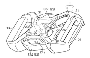
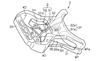
- the front view which shows the front view structure of the male member and female member which concern on the embodiment.
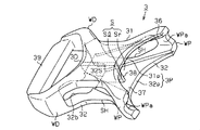
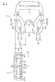
- the top view which shows the planar view structure seen from the front side of the male member which concerns on the embodiment, and the cross-sectional structure seen from the front side of the female member.
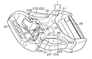
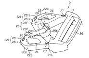
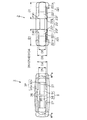
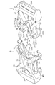
- the perspective view which shows an example of the assembly
- an embodiment of a buckle according to the present invention will be described with reference to the drawings.
- the overall structure of the buckle 1 will be described with reference to FIGS. 1 and 2.
- an arm 22 constituted by a pair of left and right first arms 22 r and second arms 221 having flexibility is formed so as to extend from the base portion 21.
- the female member 3 of the buckle 1 is formed in a flat cylindrical shape, and has a front wall 31 as an upper plate and a back wall 32 as a lower plate that face each other and spread in the flat direction.
- An insertion port 3P into which the pair of arms 22 are inserted is formed at one cylindrical end (the right cylindrical end in FIGS.
- the front wall 31 side of the buckle 1 is the front side
- the back wall 32 side of the buckle 1 is the back side.
- each of the pair of arms 22 included in the male member 2 is flattened in a plan view in which the tip end is enormous in plan view opposite to the plane including the pair of arms 22. Is formed. Further, the distal ends of the pair of arms 22 have an inclined surface 22I that tapers toward the distal end in a plan view facing the plane in which the arms 22 are included.
- the inclined surface 22I includes an inner inclined surface 22Ii formed on the inner side in the left-right direction and an outer inclined surface 22Io formed on the outer side in the left-right direction.
- the right outer surface of the right arm 22 and the left outer surface of the left arm 22 are arm locking portions 22S that are intermediate portions in the insertion direction in a plan view facing the plane in which the pair of arms 22 are included.
- locked portions 23 protruding in the thickness direction of the arms 22 are formed.
- the locked portion 23 is located at the end where the arm 22 faces and a pair of front side convex portions 23F as the first locked convex portion protruding from the surface of the arm 22 and the rear surface of the arm 22 It is comprised by the back side convex part 23B as the made 2nd to-be-latched convex part.
- an arm hole 24 is formed so as to penetrate from the front side to the back side of the arm 22 in a rhombus section and extending in the direction in which the arm 22 extends (the insertion direction). ing.
- the male arm 22 is configured so as to be plane-symmetric with respect to the plane including the pair of arms 22, that is, the structure of the pair of arms 22 viewed from the front side is the same as the structure of the pair of arms 22 viewed from the back side.
- the member 2 is formed.
- sink marks are generated when the male member 2 is formed by, for example, resin molding while ensuring the strength of the arms 22. It is possible to avoid this.
- proximal end positioning ribs 27 are disposed on the front and rear surfaces of the arm 22 near the proximal end
- distal end positioning ribs 28 are disposed on the front and rear surfaces of the arm 22 near the distal end.
- the distance between the outer surface of the pair of arms 22 and the inner surface of the female member 3 is determined by the proximal end positioning rib 27.
- a bridge 25 as a flexible band-shaped connecting member that connects the pair of arms 22 to each other is near the tip of the arm 22 and is to be locked. It is formed closer to the base end than 23.
- Each of the both ends 25 a of the bridge 25 is formed to extend from one arm 22 toward the other arm 22. More specifically, the end 25a of the bridge 25 connected to one arm 22 is in a state where no external force is applied to the arm 22 (the state shown in FIGS. 3 and 4), and the base end of the arm 22 Is formed so as to coincide with the tangential direction of the arc C drawn by the connecting portion between the arm 22 and the bridge 25.
- the intermediate portion 25 b of the bridge 25 is formed so as to bend toward the base portion 21 in the middle between the one arm 22 and the other arm 22. For this reason, even if an excessive external force acting on the pair of arms 22 acts in the direction of widening the distance between the pair of arms 22, a shearing force is generated at the connection portion between each of the pair of arms 22 and the bridge 25. It becomes difficult to do.
- a belt holding portion 26 is provided on the opposite side of the base portion 21 from the arm 22 so that the belt fastened by the buckle 1 is held so that its length can be varied.
- the front wall 31 of the female member 3 has an X shape when viewed from the front side and is surrounded by four edges curved inward.
- the back wall 32 of the female member 3 has an X shape when viewed from the back side and is surrounded by four edges curved inward.
- the pair of insertion side connection walls WP near the insertion port 3P and the pair of open side connection walls WD near the opening port are connected to the front wall 31.
- the back wall 32 is connected to each other.
- guide surfaces WPa are formed on the inner surfaces of the pair of insertion-side connecting walls WP so as to align with the outer surfaces of the base ends of the pair of arms 22 in a state where the male member 2 is connected to the female member 3.
- a rectangular insertion port 3P as viewed from a direction parallel to the insertion direction is provided at one end of the cylinder in the insertion direction of the female member 3 by the front wall 31, the back wall 32, and the insertion side connecting wall WP. It is formed in the form of being framed.
- a rectangular opening 3 ⁇ / b> D as viewed from a direction parallel to the insertion direction has four sides thereof by the front wall 31, the back wall 32, and the opening-side connecting wall WD. It is formed in the form of being framed.
- the opening edge of the insertion port 3P of the female member 3 includes a front-side insertion edge 31p that is an edge near the insertion port 3P on the front wall 31 and a back-side insertion edge 32p that is an edge near the insertion port 3P on the back wall 32.
- Each of the front-side insertion edge 31p and the back-side insertion edge 32p has a curved shape so as to project toward the opening 3D, and in plan view facing the outer surface of the front wall 31 and the outer surface of the back wall 32 They are formed so as to overlap each other. Further, in a plan view facing the outer surface of the front wall 31 and the outer surface of the back wall 32, the front wall 31 and the back wall 32 so that the front-side insertion edge 31 p and the front-side opening edge 31 d follow the outer shape of the pair of arms 22. The outer shape is formed. In the state where the male member 2 is connected to the female member 3, the insertion port 3P is formed so as to be plane-symmetric with respect to the plane including the pair of arms 22.
- the aesthetic appearance based on the functional unity between the male member 2 and the female member 3 is enhanced.
- the insertion member 3P in the female member 3 and the tip portions of the pair of arms 22 are symmetrical with each other, so that the male member 2 is coupled to the female member 3. At this time, the pair of arms 22 are easily inserted into the insertion port 3P.
- the opening edge of the opening 3D of the female member 3 includes a front opening 31d that is the edge near the opening 3D on the front wall 31 and a back opening 32d that is the edge near the opening 3D on the back wall 32. And are included.
- the opening 3D is formed so as to be asymmetric with respect to the plane including the pair of arms 22.
- the front opening edge 31d has a curved shape so as to project toward the insertion port 3P.
- the outer shape of the front wall 31 is formed such that the front-side insertion edge 31 p and the front-side opening edge 31 d follow the outer shape of the pair of arms 22.
- the front wall 31 is formed so that the pair of arms 22 are not exposed from the opening 3D in a plan view facing the outer surface of the front wall 31. (See FIGS. 1 and 2).
- the aesthetic appearance based on the functional unity between the male member 2 and the female member 3 is enhanced in a state where the male member 2 is connected to the female member 3 as in the insertion port 3P.
- the back side opening edge 32d has a curved shape so as to project toward the insertion port 3P, similarly to the front side opening edge 31d.
- the back-side opening edge 32d has a locking edge 32S that is further depressed toward the insertion port 3P than the front-side opening edge 31d in a plan view facing the outer surface of the back wall 32.
- the locking edge 32S is an edge closest to the insertion port 3P in the plan view facing the outer surface of the back wall 32 and extending in the left-right direction, and both ends of the bottom edge in the left-right direction in the insertion direction. It consists of a pair of extending side edges. In a state where the male member 2 is connected to the female member 3, the pair of arms 22 are exposed from the opening 3D as much as the locking edge 32S is formed in a plan view facing the outer surface of the back wall 32. Will come to do.
- the bottom edge constituting the locking edge 32S is in contact with the pair of back side convex portions 23B, and only the pair of back side convex portions 23B are engaged.
- the back wall 32 is formed so as to be exposed from the stop edge 32S (see FIGS. 1 and 2).
- the back-side convex portion 23B of the pair of arms 22 contacts the bottom edge of the locking edge 32S, and the back-side convex portion 23B moves toward the insertion port 3P. It becomes difficult to move. That is, it is locked that the male member 2 is detached from the female member 3 by the engagement between the locking edge 32S and the pair of back side convex portions 23B.
- the female member is compared with a configuration in which such a locking portion is separately formed. It is possible to make the configuration of 3 simpler.
- a front side guide groove 36 extending in the insertion direction is formed on the inner surface of the front wall 31.
- the front side guide groove 36 is widened to the open side 3D side of the front side insertion groove 36a and the front side insertion groove 36a formed so that the groove width becomes narrower at a constant rate from the front side insertion edge 31p toward the open port 3D.
- a locking groove 36S is formed so as to overlap the locking edge 32S described above in a plan view facing the outer surface of the back wall 32.
- the front-side convex portions 23F of the pair of arms 22 are slidably contacted with the groove side walls of the front-side insertion groove 36a and guided to the locking groove 36S.
- the front side convex portions 23F of the pair of arms 22 abut against the groove side walls of the locking grooves 36S, and the front side convex portions 23F move to the insertion port 3P side. It becomes difficult to do.
- a back side guide groove 37 extending in the insertion direction is formed on the inner surface of the back wall 32.
- the back side guide groove 37 is formed so that the groove width becomes narrow from the back side insertion edge 32p to the locking edge 32S.
- the groove side wall constituting the back side guide groove 37 is formed so as to overlap the above-described front side insertion groove 36a in a plan view facing the outer surface of the back wall 32.
- the female member 3 is formed with a pair of arm insertion holes SH facing each other in a direction orthogonal to the insertion direction.
- the pair of arm insertion holes SH are formed in a rectangular shape whose four sides are bordered by the front wall 31, the back wall 32, the insertion-side connection wall WP, and the open-side connection wall WD when viewed from a direction parallel to the left-right direction. Yes. Further, the opening edges of the pair of arm insertion holes SH are formed so as to follow the inner peripheral surface 24a of the arm hole 24 of the pair of arms 22 described above.
- a dividing wall 38 that connects the center in the left-right direction of the front-side guide groove 36 and the center in the left-right direction of the back-side guide groove 37 is formed so as to extend in the insertion direction.
- the insertion wall 3P is divided into two in the longitudinal direction by the dividing wall 38, and the internal space S of the female member 3 is divided into two in the left-right direction.
- a first accommodation space Sr and a second accommodation space S1 in which the pair of arms 22r and 22l are accommodated separately are formed inside the female member 3.
- the buckle 1 of the present embodiment when the buckle 1 is viewed from the front side, the pair of left and right arms 22r and 22l are accommodated in the first accommodation space Sr and the second accommodation space Sl, respectively, and the locking edge 32S.
- the state in which the locked portion 23 is engaged is the prescribed assembly position of the male member 2 and the female member 3.
- the dividing wall 38 having such a configuration, the front wall 31 and the back wall 32 of the female member 3 are prevented from being bent.
- a belt attaching portion 39 to which a belt fastened by the buckle 1 is attached so that its length cannot be changed is provided at the end of the female member 3 in the insertion direction.
- the belt attaching portion 39 is provided with three bottomed holes in order to reduce the weight of the buckle 1.
- FIG. 7 shows a comparison between the plan view structure of the male member 2 and the front view structure of the female member 3 viewed from the insertion direction.
- FIG. 8 shows a front view structure of the male member 2 viewed from the protruding direction on the pair of arms 22 side and a front view structure of the female member 3 viewed from the insertion direction.
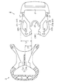
- FIG. 9 shows the plan view structure of the male member 2 and the plan view structure of the female member 3 in comparison.
- the pair of arms 22 constituting the male member 2 has a width D1 from the arm locking portion 22S to the inner end larger than the opening width D2 in the short direction of the insertion port 3P of the female member 3. It is formed to be sufficiently large. For this reason, the pair of arms 22 has a shape in which the width of the distal end portion is larger than the opening width D2 in the short direction of the insertion port 3P in the plan view (D1> D2). According to such a configuration, the thickness direction (X direction in the example of FIG. 7) at the distal ends of the pair of arms 22 and the short direction (Y direction in the example of FIG. 7) at the insertion port 3P are different from each other.
- the outer inclined surface 22Io and the inner inclined surface 22Ii of the pair of arms 22 are inserted into the front side while the pair of arms 22 are being inserted into the insertion port 3P. It abuts on the edge 31p and the back side insertion edge 32p.
- each of the pair of arms 22 is stopped while being inserted into the insertion port 3P, and the male member 2 and the female member 3 are stopped. Is prevented from being engaged in a wrong manner.
- the front end of the pair of arms 22 constituting the male member 2 has a thickness D3 in a region where the locked portion 23 is formed, and a front side guide groove 36 and a back side guide groove 37 are formed. It is formed to be smaller than the opening width D4 in the short direction of the insertion port 3P in the region (D3 ⁇ D4).
- the distal ends of the pair of arms 22 have a thickness D3 in the region where the locked portion 23 is formed, and the short side of the insertion port 3P in the region where the front side guide groove 36 and the back side guide groove 37 are not formed. It is formed to be larger than the opening width D5 in the direction (D3> D5).
- the thickness D6 in the region where the locked portion 23 is not formed at the distal ends of the pair of arms 22 is the short direction of the insertion port 3P in the region where the front side guide groove 36 and the back side guide groove 37 are not formed. Is formed to be smaller than the opening width D5 at (D6 ⁇ D5).
- the front-side convex portion 23F and the back-side convex portion 23B have the front-side guide groove 36 and the back-side guide groove whose groove width gradually decreases in the insertion direction. Since the guide is guided to the locking edge 32 ⁇ / b> S while being in contact with 37, the pair of arms 22 are accurately guided to the engagement position with the female member 3.
- the front side guide groove 36 and the back side guide groove 37 in the insertion port 3P are formed.
- the front side convex portion 23F and the back side convex portion 23B come into contact with the front side insertion edge 31p and the back side insertion edge 32p.
- a pair of arm 22 is inserted in the position which does not connect to the latching edge 32S from the horizontal direction of the female member 3, and the incorrect assembly
- each of the pair of arms 22 has a width D ⁇ b> 1 from the arm locking portion 22 ⁇ / b> S that becomes the maximum width at the tip portion thereof to the inner end of the front side guide groove 36 and the back side guide groove 37. It is formed to be sufficiently larger than the maximum distance D7 in the left-right direction between the groove side surface and the dividing wall 38 (D1> D7).
- the maximum width D1 of the tip portions of the pair of arms 22 is such that the groove side surfaces of the guide grooves 36 and 37 extending from the insertion port 3P to the locking edge 32S formed on the open port 3D side, and the dividing wall 38 It is larger than any of the distances.
- the assembly of the male member 2 and the female member 3 is performed from a position shifted in a plane including the pair of arms 22, thereby assembling the arm for the second accommodation space Sl.
- the tip of the first arm 22r abuts against the dividing wall 38 in the middle thereof.
- the erroneous engagement between the male member 2 and the female member 3 is automatically stopped in the middle of the insertion, and erroneous assembly due to the displacement of the assembly position in the horizontal direction is suppressed.
- the pair of arms 22 is inserted in the insertion direction from the insertion port 3P in a defined manner so that the thickness direction at the distal ends of the pair of arms 22 and the short direction of the insertion port 3P coincide.
- the distal ends of the pair of arms 22 enter the female member 3 while the outer surface of the arms 22 is in sliding contact with the guide surface WPa.
- a pair of front side convex portions 23F projecting from the surface of the arm 22 are guided to the locking groove 36S along the front side insertion groove 36a.
- a pair of back side convex portions 23 ⁇ / b> B protruding from the back surface of the arm 22 is guided along the back side guide groove 37 to the opening 3 ⁇ / b> D.
- the thickness D3 of the distal end portion of the pair of arms 22 in the region where the locked portion 23 is formed is the region where the front side guide groove 36 and the back side guide groove 37 are formed in the short direction of the insertion port 3P.
- the opening width D4 is smaller than the opening width D4 and larger than the opening width D5 in the unformed region of the front side guide groove 36 and the back side guide groove 37 (D5 ⁇ D3 ⁇ D4).
- 23 guides each pair of arms 22 to the opening 3D while being in sliding contact with the groove side surfaces of the front guide groove 36 and the back guide groove 37.
- the outer inclined surface 22Io is guided to the opening 3D side while being in sliding contact with the guide surface WPa, whereby the pair of arms 22 is guided to the opening 3D along the outer inclined surface 22Io.
- the inner inclined surface 22Ii is guided to the opening 3D while being in sliding contact with the dividing wall 38, whereby the pair of arms 22 is guided to the opening 3D along the outer inclined surface 22Io.
- the pair of arms 22 is cooperated with the outer inclined surface 22Io and the inner inclined surface 22Ii, the guide grooves 36 and 37, and the dividing wall 38. The force which guides each of these in the insertion direction of the insertion port 3P will act. Thereby, each arm 22 smoothly moves to the engagement position with the female member 3 even though the width D1 of the distal end portion of the pair of arms 22 is larger than the opening width in the short direction of the insertion port 3P. Be guided.
- each of the pair of arms 22 has a shape that protrudes outward in the left-right direction at the arm locking portion 22S.
- the guide surface WPa in a pair of insertion side connection wall WP has a shape which aligns with the outer surface in the base end of a pair of arm 22. FIG. Therefore, when the pair of arms 22 is inserted into the female member 3, the outer surface of each of the pair of arms 22 protrudes outward from the guide surface WPa, so that the outer surface of the arm 22 is laterally moved by the guide surface WPa. It will be pushed closer to the center.
- the pair of arms 22 is bent most greatly toward the center in the left-right direction.
- the pushing of the guide surface WPa with respect to the outer surface of the arm 22 is released, and the bending in the pair of arms 22 follows the guidance of the front insertion groove 36a and the back guide groove 37. It becomes.
- the groove widths of the front-side insertion groove 36a and the back-side guide groove 37 are formed so as to narrow at a constant rate from the insertion port 3P toward the opening port 3D.
- the pair of arms 22 while the pair of arms 22 is inserted according to the guidance of the front side insertion groove 36a and the back side guide groove 37, the pair of arms 22 enters the female member 3 while being bent at a constant rate toward the center in the left-right direction. It becomes like this.
- the arm locking portion 22S passes through the guide surface WPa, the external force with respect to the arm 22 is temporarily increased. Therefore, the engagement between the arm locking portion 22S and the guide surface WPa causes a pair of forces. It is possible to temporarily fix the arm 22 to the female member 3.
- the front side convex portion 23F reaches the locking groove 36S, and the back side convex portion 23B reaches the opening 3D.
- the locking groove 36S is expanded from the front-side insertion groove 36a and the locking edge 32S is expanded from the back-side guide groove 37
- the pair of arms 22 bent toward the center in the left-right direction.
- they extend outward in the left-right direction according to the shape of the locking groove 36S and the shape of the locking edge 32S.
- the front-side convex portion 23F comes into contact with the groove side wall of the locking groove 36S, and the front-side convex portion 23F is difficult to move to the insertion port 3P side.
- the back side convex portion 23B comes into contact with the bottom edge of the locking edge 32S, and the back side convex portion 23B is difficult to move to the insertion port 3P side.
- the male member 2 is coupled to the female member 3.
- the pair of arms 22 is inserted from the insertion port 3P in the insertion direction by an unspecified method in which the thickness direction at the distal ends of the pair of arms 22 and the short direction of the insertion port 3P are different from each other. Then, the outer inclined surface 22Io and the inner inclined surface 22Ii at the tips of the pair of arms 22 are first brought into contact with the front-side insertion edge 31p and the back-side insertion edge 32p. Even if a force is further applied to insert the pair of arms 22 into the insertion port 3P, the width of the distal end portions of the pair of arms 22 is sufficiently larger than the opening width D2 in the short direction of the insertion port 3P. Since it has a large shape, the distal end portions of the pair of arms 22 are prevented from being inserted into the insertion port 3P. Thereby, it is suppressed that the male member 2 and the female member 3 are engaged in a wrong manner.
- the effects listed below can be obtained.
- the thickness of the tip portion is larger than the opening width D2 in the short direction of the insertion port 3P.
- the width of the tip is larger than the opening width D2 in the short direction of the insertion port. Therefore, when the male member 2 and the female member 3 are assembled in a defined manner in which the thickness direction at the tips of the pair of arms 22 matches the short direction at the insertion port, the pair of arms 22 are inserted into the insertion port 3P. As a result, the male member 2 and the female member 3 can be smoothly engaged.
- the opening in the short direction of the insertion port is formed. Since the width at the tip of each arm is larger than the width D2, it is structurally prevented that each arm 22 is inserted into the insertion port 3P, and the male member 2 and the female member 3 are engaged in an erroneous manner. Is suppressed. For this reason, it becomes possible to suppress erroneous assembly of the male member 2 and the female member 3 while facilitating the assembly of the male member 2 and the female member 3.
- a front-side insertion edge 31p and a back-side insertion edge 32p for guiding the pair of arms 22 to the engagement position with the female member 3 were formed from the opening edge of the insertion port 3P in the female member 3 to the opening 3D.
- the thickness D3 of each arm 22 including the locked portion 23 is smaller than the opening width D4 in the short direction of the insertion port 3P in the region where the front side guide groove 36 and the back side guide groove 37 are formed, and It was formed to be larger than the opening width D5 in the short direction in the region where the front side guide groove 36 and the back side guide groove 37 were not formed.
- the locked portion 23 is guided to the locking edge 32S while being in sliding contact with the groove side surfaces of the front side guide groove 36 and the back side guide groove 37. Accordingly, the pair of arms 22 are accurately guided to the engagement position with the female member 3, and the smooth assembly of the male member 2 and the female member 3 is realized.
- each arm 22 is inserted in the position which does not connect to the latching edge 32S from the horizontal direction of the female member 3, and the incorrect assembly
- the locked portion 23 is provided at the end where the pair of arms 22 face each other, and the maximum width D1 at the tip of each arm 22 is determined from the groove widths of the front side guide groove 36 and the back side guide groove 37 divided by the dividing wall 38. Also formed to be larger. For this reason, as one mode of misassembly of the male member 2 and the female member 3, when the pair of arms 22 is inserted into the insertion port 3P from a position shifted in a plane including the pair of arms 22, The arm 22l (22r) on the side different from the assembly arm 22r (221) abuts on the dividing wall 38.
- the thickness of the distal end portion of the arm 22 is determined at the locked portion 23, and the maximum width D1 at the distal end portion is determined based on the portion of the locked portion 23. For this reason, whether the assembly is in an unspecified manner such that the thickness direction at the distal ends of the pair of arms 22 and the short direction in the insertion port 3P are different from each other, or the assembly in a manner in which the assembly position in the horizontal direction is shifted, It is possible to reliably suppress the locked portion 23 projecting from the distal end portion of 22 from entering the inside of the female member 3.
- each arm 22 is smoothly moved to the engagement position with the female member 3 while the width D1 of the distal end portion of the pair of arms 22 is larger than the opening width D2 in the short direction of the insertion port 3P. Be guided by. Further, according to such a configuration, each arm 22 is guided by the front-side guide groove 36 and the back-side guide groove 37 through the locked portion 23, and each of the respective through the outer inclined surface 22Io by the guide surface WPa of the insertion port 3P. Due to the synergistic effect with the guidance of the arm 22, the male member 2 and the female member 3 can be engaged more accurately and smoothly.
- the pair of left and right arms 22r and 22l are connected by a bridge 25 which is a connecting member. For this reason, even if the male member 2 and the female member 3 are to be assembled in a manner different from the prescribed assembly position, the bridge 25 is brought into contact with the front-side insertion edge 31p and the back-side insertion edge 32p of the female member 3. Thereby, the incorrect assembly
- the said embodiment can also be implemented with the following aspects.
- the intermediate portion 25 b of the bridge 25 is formed to be curved in a convex shape toward the base portion 21 in the middle between the one arm 22 and the other arm 22, but is not limited thereto. Instead, it may be formed so as to curve in a convex shape toward the tips of the pair of arms 22. In this case, it is necessary to prevent the dividing wall 38 provided on the female member 3 from interfering with the bridge 25.
- the bridge 25 is disposed on the male member 2, the present invention is not limited thereto, and the bridge 25 may not be provided.
- a so-called center bar is provided that protrudes from the base 21 toward the insertion direction of the arm 22 and has a function of guiding the male member 2 when the arm 22 is inserted into the female member 3. You may do it. Even in this case, it is possible to make it difficult for an external force to increase the interval between the arms 22 to act on the arms 22.
- the center bar guide portion for guiding the center bar instead of the dividing wall 38 at the position where the dividing wall 38 was provided.
- the outer inclined surface 22Io and the inner inclined surface 22Ii tapering toward the tip in a plan view facing the plane including the pair of arms 22 were formed at the tip of each of the pair of arms 22.
- the present invention is not limited to this, and only the outer inclined surface 22Io or the inner inclined surface 22Ii may be formed at the tip of each of the pair of arms 22. Therefore, it is possible to simplify the configuration of the male member 2 while obtaining the effect according to the above (4).
- the shape of the tip of each of the pair of arms 22 is a semi-elliptical cross section having a predetermined curvature that tapers toward the tip in a plan view facing the plane including the pair of arms 22. Also good.
- the shape of the tip portions of the pair of arms 22 may be any shape that is flat and massive, and the tip portions of the pair of arms 22 in a plan view facing the plane that includes the pair of arms 22. It is sufficient that the thickness at is smaller than the opening width in the short direction of the insertion port 3P and the width at the tip of the pair of arms 22 is larger than the opening width in the short direction of the insertion port 3P.
- the present invention is not limited thereto, and the dividing wall 38 may be omitted.
- the engaged portion 23 is provided at the end where the pair of arms 22 face each other, and the maximum width D1 at the tip of each arm 22 is larger than the groove width D7 of the front side guide groove 36 and the back side guide groove 37 divided by the dividing wall 38. It formed so that it might become.
- the maximum width D1 at the tip of the arm 22 may be equal to or less than the groove widths of the front-side guide groove 36 and the back-side guide groove 37 divided by the dividing wall 38. Even in this case, it is possible to obtain the same effects as the above (1) and (2).
- the to-be-latched part 23 should just be provided in the position which can be engaged with the latching edge 32S among the front-end
- a front guide groove 36 formed so that the groove width narrows at a constant rate from the front insertion edge 31p toward the opening 3D was formed.
- a back-side guide groove 37 is formed on the inner surface of the back wall 32 of the female member 3 so that the groove width becomes narrower at a constant rate from the back-side insertion edge 32p toward the opening 3D.
- a groove in the front wall 31 or the back wall 32 of the female member 3 is formed on the front wall 31 or the back wall 32 of the female member 3 so that the groove width decreases with a predetermined curvature from the front insertion edge 31p and the back insertion edge 32p toward the opening 3D. It may be formed on the surface. Even in this case, it is possible to obtain the effect according to the above (2).
- a groove having a constant groove width extending linearly from the front insertion edge 31p and the back insertion edge 32p toward the opening 3D is formed on the inner surface of the front wall 31 or the rear wall 32 of the female member 3. Also good.
- the groove formed on the inner surface of the front wall 31 or the back wall 32 of the female member 3 is the engagement of the locked portion 23 formed in the thickness direction of the distal end portion of the pair of arms 22 from the insertion port 3P. Any shape that can be guided to the stop edge 32S is acceptable.
- the thickness D3 of each arm 22 including the locked portion 23 of the pair of arms 22 is larger than the opening width D4 in the short direction of the insertion port 3P in the region where the front side guide groove 36 and the back side guide groove 37 are formed. And the opening width D5 in the short direction in the region where the front side guide groove 36 and the back side guide groove 37 are not formed is formed.
- the thickness D3 of each arm 22 including the locked portion 23 is a pair of arms 22 in a prescribed manner in which the thickness direction at the distal ends of the pair of arms 22 and the short direction at the insertion port 3P match. Any thickness may be used as long as the arm 22 can be inserted into the insertion port 3P. Even in this case, it is possible to obtain the same effect as the above-mentioned (1).
- the base end positioning rib 27 or the front end positioning rib 28 is omitted, it is possible to obtain the same effects as the above (1) to (5).
- the convex rib is formed on the inner surface of the female member 3 and the male member 2 is connected to the female member 3, the pair of arms are pressed against the convex rib. Even if the positioning rib 28 is omitted, rattling of the male member 2 can be reduced.
- the locking edge 32S in the opening 3D is composed of a bottom edge extending in the left-right direction and a side edge extending in the insertion direction.
- the locking edge 32S may be formed so as to be convex in the insertion direction of the arm 22 or the removal direction of the arm 22.
- a front convex portion 23F is formed near the front end of the pair of arms 22, and a back convex portion 23B is formed near the rear end of the pair of arms 22.
- a configuration in which the engagement portion between the male member 2 and the female member 3 is limited to the front side convex portion 23F and the locking groove 36S that is, a configuration in which the back side convex portion 23B is omitted. If it is such a structure, it is also possible to omit the back side guide groove 37 other than the back side convex part 23B. Therefore, it is possible to simplify the configuration of the male member 2 and the female member 3 while obtaining the effect according to the above (1).
Landscapes
- Buckles (AREA)
Applications Claiming Priority (2)
| Application Number | Priority Date | Filing Date | Title |
|---|---|---|---|
| JP2010130516A JP5469541B2 (ja) | 2010-06-07 | 2010-06-07 | バックル |
| JP2010-130516 | 2010-06-07 |
Publications (1)
| Publication Number | Publication Date |
|---|---|
| WO2011155452A1 true WO2011155452A1 (ja) | 2011-12-15 |
Family
ID=45098059
Family Applications (1)
| Application Number | Title | Priority Date | Filing Date |
|---|---|---|---|
| PCT/JP2011/062951 Ceased WO2011155452A1 (ja) | 2010-06-07 | 2011-06-06 | バックル |
Country Status (4)
| Country | Link |
|---|---|
| JP (1) | JP5469541B2 (enExample) |
| KR (1) | KR101253442B1 (enExample) |
| TW (1) | TWI486133B (enExample) |
| WO (1) | WO2011155452A1 (enExample) |
Citations (4)
| Publication number | Priority date | Publication date | Assignee | Title |
|---|---|---|---|---|
| JP2002101915A (ja) * | 2000-09-27 | 2002-04-09 | Ykk Corp | バックル |
| JP2002101916A (ja) * | 2000-09-28 | 2002-04-09 | Ykk Corp | バックル |
| JP2009011492A (ja) * | 2007-07-03 | 2009-01-22 | Ykk Corp | バックル |
| WO2009093313A1 (ja) * | 2008-01-23 | 2009-07-30 | Ykk Corporation | バックル |
Family Cites Families (1)
| Publication number | Priority date | Publication date | Assignee | Title |
|---|---|---|---|---|
| JP2008178570A (ja) * | 2007-01-25 | 2008-08-07 | Ykk Corp | バックル |
-
2010
- 2010-06-07 JP JP2010130516A patent/JP5469541B2/ja active Active
-
2011
- 2011-05-31 TW TW100118968A patent/TWI486133B/zh active
- 2011-06-03 KR KR1020110053879A patent/KR101253442B1/ko active Active
- 2011-06-06 WO PCT/JP2011/062951 patent/WO2011155452A1/ja not_active Ceased
Patent Citations (4)
| Publication number | Priority date | Publication date | Assignee | Title |
|---|---|---|---|---|
| JP2002101915A (ja) * | 2000-09-27 | 2002-04-09 | Ykk Corp | バックル |
| JP2002101916A (ja) * | 2000-09-28 | 2002-04-09 | Ykk Corp | バックル |
| JP2009011492A (ja) * | 2007-07-03 | 2009-01-22 | Ykk Corp | バックル |
| WO2009093313A1 (ja) * | 2008-01-23 | 2009-07-30 | Ykk Corporation | バックル |
Also Published As
| Publication number | Publication date |
|---|---|
| JP5469541B2 (ja) | 2014-04-16 |
| JP2011254915A (ja) | 2011-12-22 |
| KR101253442B1 (ko) | 2013-04-11 |
| TWI486133B (zh) | 2015-06-01 |
| KR20110134290A (ko) | 2011-12-14 |
| TW201200055A (en) | 2012-01-01 |
Similar Documents
| Publication | Publication Date | Title |
|---|---|---|
| JP2011254928A (ja) | バックル | |
| EP1400183B1 (en) | Buckle | |
| US20080178438A1 (en) | Buckle | |
| WO2011093390A1 (ja) | コネクタ | |
| WO2013121559A1 (ja) | バックル | |
| JP5469543B2 (ja) | バックル | |
| JP2004152620A (ja) | コネクタ | |
| JP5469541B2 (ja) | バックル | |
| JP5538074B2 (ja) | バックル | |
| JP6605296B2 (ja) | バックル | |
| KR101242935B1 (ko) | 버클 | |
| JP5469542B2 (ja) | バックル | |
| KR101241560B1 (ko) | 버클 | |
| JP5902739B2 (ja) | バックル | |
| JP5328895B2 (ja) | サイドリリースバックル | |
| HK1176831B (en) | Buckle | |
| HK1179836B (en) | Buckle |
Legal Events
| Date | Code | Title | Description |
|---|---|---|---|
| 121 | Ep: the epo has been informed by wipo that ep was designated in this application |
Ref document number: 11792409 Country of ref document: EP Kind code of ref document: A1 |
|
| NENP | Non-entry into the national phase |
Ref country code: DE |
|
| 122 | Ep: pct application non-entry in european phase |
Ref document number: 11792409 Country of ref document: EP Kind code of ref document: A1 |