WO2011155452A1 - Buckle - Google Patents
Buckle Download PDFInfo
- Publication number
- WO2011155452A1 WO2011155452A1 PCT/JP2011/062951 JP2011062951W WO2011155452A1 WO 2011155452 A1 WO2011155452 A1 WO 2011155452A1 JP 2011062951 W JP2011062951 W JP 2011062951W WO 2011155452 A1 WO2011155452 A1 WO 2011155452A1
- Authority
- WO
- WIPO (PCT)
- Prior art keywords
- pair
- arms
- female member
- insertion port
- opening
- Prior art date
Links
Images


Classifications
-
- A—HUMAN NECESSITIES
- A44—HABERDASHERY; JEWELLERY
- A44B—BUTTONS, PINS, BUCKLES, SLIDE FASTENERS, OR THE LIKE
- A44B11/00—Buckles; Similar fasteners for interconnecting straps or the like, e.g. for safety belts
- A44B11/25—Buckles; Similar fasteners for interconnecting straps or the like, e.g. for safety belts with two or more separable parts
- A44B11/26—Buckles; Similar fasteners for interconnecting straps or the like, e.g. for safety belts with two or more separable parts with push-button fastenings
- A44B11/266—Buckles; Similar fasteners for interconnecting straps or the like, e.g. for safety belts with two or more separable parts with push-button fastenings with at least one push-button acting parallel to the main plane of the buckle and perpendicularly to the direction of the fastening action
-
- A—HUMAN NECESSITIES
- A44—HABERDASHERY; JEWELLERY
- A44B—BUTTONS, PINS, BUCKLES, SLIDE FASTENERS, OR THE LIKE
- A44B11/00—Buckles; Similar fasteners for interconnecting straps or the like, e.g. for safety belts
- A44B11/25—Buckles; Similar fasteners for interconnecting straps or the like, e.g. for safety belts with two or more separable parts
- A44B11/26—Buckles; Similar fasteners for interconnecting straps or the like, e.g. for safety belts with two or more separable parts with push-button fastenings
-
- A—HUMAN NECESSITIES
- A44—HABERDASHERY; JEWELLERY
- A44B—BUTTONS, PINS, BUCKLES, SLIDE FASTENERS, OR THE LIKE
- A44B11/00—Buckles; Similar fasteners for interconnecting straps or the like, e.g. for safety belts
- A44B11/25—Buckles; Similar fasteners for interconnecting straps or the like, e.g. for safety belts with two or more separable parts
Definitions
- the present invention relates to a buckle in which a male member is detachably connected to a female member.
- Patent Document 1 a buckle including a male member and a female member is known.
- the male member described in Patent Literature 1 is provided with a pair of arms having an engaging portion at the tip and having a plane-symmetric shape extending from the base.
- a linear center bar is provided at the center of each arm so as to extend from the base.
- the female member is provided with a flat cylindrical housing portion having an insertion port into which the pair of arms are inserted so that the pair of arms and the center bar are housed therein.
- a partition piece that forms a space in which the center bar is accommodated is provided at the center of the accommodation portion.
- the latching convex part engaged with the engaging part of a male member is formed in the inner surface in the accommodating part of a female member.
- the male member and the female member face each other so that the direction in which the pair of arms are aligned and the longitudinal direction of the insertion port coincide, and the pair of arms is inserted from this state. It is inserted into the mouth. And while a pair of arms are guided to the inner surface of the accommodating part and the center bar is guided to the partition piece, the engaging part of the male member is engaged with the engaging convex part of the female member. Become. Thereby, the arm of the female member is accurately guided to the housing portion of the male member, and the male member is inserted into the female member in a wrong manner, that is, erroneous assembly is suppressed.
- the present invention has been made in view of such circumstances, and provides a buckle capable of suppressing erroneous assembly between a male member and a female member while facilitating the assembly of the male member and the female member. With the goal.
- the present invention has a male member having a pair of arms having a flat and massive tip portion and an insertion port which is a flat opening into which the pair of arms are inserted at one end of the cylinder.
- the pair of arms has a short thickness of the insertion opening at a tip portion of the pair of arms in a plan view facing a plane including the pair of arms.
- the gist of the invention is that it has a shape that is smaller than the opening width in the hand direction and that the width at the distal end portion of the pair of arms is larger than the opening width in the short direction of the insertion opening.
- the pair of arms to be inserted into the insertion slot has a tip portion whose thickness is smaller than the opening width in the short direction of the insertion slot in a plan view facing a plane including the pair of arms.
- the shape is small and the width of the tip is larger than the opening width in the short direction of the insertion slot. Therefore, when the male member and the female member are assembled in a defined manner such that the thickness direction at the tips of the pair of arms coincides with the short direction at the insertion port, the pair of arms are inserted into the insertion port.
- the engagement between the male member and the female member can be performed smoothly.
- the opening width in the short direction of the insertion port Since the width at the tip portion of each arm is larger than that, it is structurally prevented that each arm is inserted into the insertion port. That is, it is suppressed that the male member and the female member are engaged in a wrong manner. For this reason, it becomes possible to suppress erroneous assembly of the male member and the female member while facilitating the assembly of the male member and the female member.
- the male member has a locked portion protruding in the thickness direction of the pair of arms at the distal end portion, and the female member is opposed to each other in the thickness direction of the pair of arms. It has an upper plate and a lower plate, and the inner surface of at least one of the upper plate and the lower plate is locked against the detachment of the male member from the female member by engagement with the locked portion. And a guide groove that guides the locked portion from the insertion port to the locking portion, and the pair of arms are in a plan view facing a plane including the pair of arms.
- the thickness of the tip in the region where the locked portion is formed is smaller than the opening width in the short direction of the insertion port in the region where the guide groove is formed, and the guide groove Larger than the opening width in the short direction of the insertion opening in the non-forming region And summarized in that a shape.
- the guide groove for guiding the pair of arms to the engagement position with the female member is formed at the opening edge of the insertion opening in the female member.
- the thickness of each arm including the locked portion is smaller than the opening width in the short direction in the region where the guide groove is formed, and the opening in the short direction in the region where the guide groove is not formed. Greater than width.
- each arm including the locked portion is larger than the opening width of the insertion port. For this reason, it will be suppressed that each arm is inserted in the position which does not communicate with a latching
- the female member has a dividing wall that divides the insertion port into two in the longitudinal direction of the insertion port, and the locked portions are provided at opposite ends of the pair of arms, respectively.
- the guide groove guides each of the pair of locked portions provided in each of the pair of arms along a groove side surface extending from the insertion port to the locking portion.
- the gist of the present invention is that the maximum width of the tip portion of each of the pair of arms is larger than the distance between the groove side surface of the guide groove and the dividing wall.
- the locked portion is provided at the end where the pair of arms face each other, and the maximum width at the tip of the pair of arms is larger than the width of each guide groove divided by the dividing wall.
- each member is assembled from a position shifted in the plane including the pair of arms, and as a result, the divided insertion opening is inserted into the divided insertion port.
- an arm on a different side from the prescribed assembly arm is inserted.
- the arm on the side different from the prescribed assembly arm abuts against the dividing wall, or the locked portion of the arm is a guide groove.
- the engagement of the male member and the female member in the wrong manner is automatically stopped during the insertion.
- the erroneous assembly resulting from the shift of the assembly position especially in the horizontal direction is suitably suppressed.
- the thickness of the tip portion is particularly large at the locked portion, and the maximum width at the tip is defined based on the portion of the locked portion.
- the tip portion of the pair of arms may be attached in an unspecified manner such that the thickness direction at the tip portion of the pair of arms is different from the short direction in the insertion port, or in a manner in which the assembly position is shifted in the horizontal direction. It is possible to reliably suppress the locked portion projecting from the inside of the female member.
- the gist of the present invention is that each of the tip portions of the pair of arms has an inclined surface that is tapered toward the tip in a plan view opposite to a plane including the pair of arms.
- the pair of arms when the pair of arms are inserted into the female member while the distal end portion tapered toward the distal end is in sliding contact with the opening edge of the insertion port, the pair of arms follows the inclination of the tapered inclined surface. Is inserted into the female member. Further, when the pair of arms is inserted into the female member while the tip portion tapered toward the tip is in sliding contact with the dividing wall, each of the pair of arms is inherently following the inclination of the tapered inclined surface. Guided to the engagement position to be located. Thereby, further smoothing for the assembly of the male member and the female member can be achieved while the width of the distal end portion is larger than the opening width in the short direction of the insertion opening.
- the male member includes a connection member that connects the pair of arms.
- a pair of arm is connected by the said connection member.
- the connecting member is brought into contact with one cylindrical end of the female member.
- attachment with a male member and a female member can be suppressed more reliably.
- the pair of arms are supported by the connection member. Thereby, the structural stability as a male member comes to be achieved.
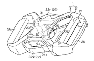
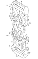
- the front view which shows the front view structure of the male member and female member which concern on the embodiment.
- the top view which shows the planar view structure seen from the front side of the male member which concerns on the embodiment, and the cross-sectional structure seen from the front side of the female member.
- the perspective view which shows an example of the assembly
- an embodiment of a buckle according to the present invention will be described with reference to the drawings.
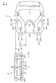
- the overall structure of the buckle 1 will be described with reference to FIGS. 1 and 2.
- an arm 22 constituted by a pair of left and right first arms 22 r and second arms 221 having flexibility is formed so as to extend from the base portion 21.
- the female member 3 of the buckle 1 is formed in a flat cylindrical shape, and has a front wall 31 as an upper plate and a back wall 32 as a lower plate that face each other and spread in the flat direction.
- An insertion port 3P into which the pair of arms 22 are inserted is formed at one cylindrical end (the right cylindrical end in FIGS.
- the front wall 31 side of the buckle 1 is the front side
- the back wall 32 side of the buckle 1 is the back side.
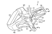
- each of the pair of arms 22 included in the male member 2 is flattened in a plan view in which the tip end is enormous in plan view opposite to the plane including the pair of arms 22. Is formed. Further, the distal ends of the pair of arms 22 have an inclined surface 22I that tapers toward the distal end in a plan view facing the plane in which the arms 22 are included.
- the inclined surface 22I includes an inner inclined surface 22Ii formed on the inner side in the left-right direction and an outer inclined surface 22Io formed on the outer side in the left-right direction.
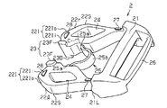
- the right outer surface of the right arm 22 and the left outer surface of the left arm 22 are arm locking portions 22S that are intermediate portions in the insertion direction in a plan view facing the plane in which the pair of arms 22 are included.
- locked portions 23 protruding in the thickness direction of the arms 22 are formed.
- the locked portion 23 is located at the end where the arm 22 faces and a pair of front side convex portions 23F as the first locked convex portion protruding from the surface of the arm 22 and the rear surface of the arm 22 It is comprised by the back side convex part 23B as the made 2nd to-be-latched convex part.
- an arm hole 24 is formed so as to penetrate from the front side to the back side of the arm 22 in a rhombus section and extending in the direction in which the arm 22 extends (the insertion direction). ing.
- the male arm 22 is configured so as to be plane-symmetric with respect to the plane including the pair of arms 22, that is, the structure of the pair of arms 22 viewed from the front side is the same as the structure of the pair of arms 22 viewed from the back side.
- the member 2 is formed.
- sink marks are generated when the male member 2 is formed by, for example, resin molding while ensuring the strength of the arms 22. It is possible to avoid this.
- proximal end positioning ribs 27 are disposed on the front and rear surfaces of the arm 22 near the proximal end
- distal end positioning ribs 28 are disposed on the front and rear surfaces of the arm 22 near the distal end.
- the distance between the outer surface of the pair of arms 22 and the inner surface of the female member 3 is determined by the proximal end positioning rib 27.
- a bridge 25 as a flexible band-shaped connecting member that connects the pair of arms 22 to each other is near the tip of the arm 22 and is to be locked. It is formed closer to the base end than 23.
- Each of the both ends 25 a of the bridge 25 is formed to extend from one arm 22 toward the other arm 22. More specifically, the end 25a of the bridge 25 connected to one arm 22 is in a state where no external force is applied to the arm 22 (the state shown in FIGS. 3 and 4), and the base end of the arm 22 Is formed so as to coincide with the tangential direction of the arc C drawn by the connecting portion between the arm 22 and the bridge 25.
- the intermediate portion 25 b of the bridge 25 is formed so as to bend toward the base portion 21 in the middle between the one arm 22 and the other arm 22. For this reason, even if an excessive external force acting on the pair of arms 22 acts in the direction of widening the distance between the pair of arms 22, a shearing force is generated at the connection portion between each of the pair of arms 22 and the bridge 25. It becomes difficult to do.
- a belt holding portion 26 is provided on the opposite side of the base portion 21 from the arm 22 so that the belt fastened by the buckle 1 is held so that its length can be varied.
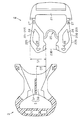
- the front wall 31 of the female member 3 has an X shape when viewed from the front side and is surrounded by four edges curved inward.
- the back wall 32 of the female member 3 has an X shape when viewed from the back side and is surrounded by four edges curved inward.
- the pair of insertion side connection walls WP near the insertion port 3P and the pair of open side connection walls WD near the opening port are connected to the front wall 31.
- the back wall 32 is connected to each other.
- guide surfaces WPa are formed on the inner surfaces of the pair of insertion-side connecting walls WP so as to align with the outer surfaces of the base ends of the pair of arms 22 in a state where the male member 2 is connected to the female member 3.
- a rectangular insertion port 3P as viewed from a direction parallel to the insertion direction is provided at one end of the cylinder in the insertion direction of the female member 3 by the front wall 31, the back wall 32, and the insertion side connecting wall WP. It is formed in the form of being framed.
- a rectangular opening 3 ⁇ / b> D as viewed from a direction parallel to the insertion direction has four sides thereof by the front wall 31, the back wall 32, and the opening-side connecting wall WD. It is formed in the form of being framed.
- the opening edge of the insertion port 3P of the female member 3 includes a front-side insertion edge 31p that is an edge near the insertion port 3P on the front wall 31 and a back-side insertion edge 32p that is an edge near the insertion port 3P on the back wall 32.
- Each of the front-side insertion edge 31p and the back-side insertion edge 32p has a curved shape so as to project toward the opening 3D, and in plan view facing the outer surface of the front wall 31 and the outer surface of the back wall 32 They are formed so as to overlap each other. Further, in a plan view facing the outer surface of the front wall 31 and the outer surface of the back wall 32, the front wall 31 and the back wall 32 so that the front-side insertion edge 31 p and the front-side opening edge 31 d follow the outer shape of the pair of arms 22. The outer shape is formed. In the state where the male member 2 is connected to the female member 3, the insertion port 3P is formed so as to be plane-symmetric with respect to the plane including the pair of arms 22.
- the aesthetic appearance based on the functional unity between the male member 2 and the female member 3 is enhanced.
- the insertion member 3P in the female member 3 and the tip portions of the pair of arms 22 are symmetrical with each other, so that the male member 2 is coupled to the female member 3. At this time, the pair of arms 22 are easily inserted into the insertion port 3P.
- the opening edge of the opening 3D of the female member 3 includes a front opening 31d that is the edge near the opening 3D on the front wall 31 and a back opening 32d that is the edge near the opening 3D on the back wall 32. And are included.
- the opening 3D is formed so as to be asymmetric with respect to the plane including the pair of arms 22.
- the front opening edge 31d has a curved shape so as to project toward the insertion port 3P.
- the outer shape of the front wall 31 is formed such that the front-side insertion edge 31 p and the front-side opening edge 31 d follow the outer shape of the pair of arms 22.
- the front wall 31 is formed so that the pair of arms 22 are not exposed from the opening 3D in a plan view facing the outer surface of the front wall 31. (See FIGS. 1 and 2).
- the aesthetic appearance based on the functional unity between the male member 2 and the female member 3 is enhanced in a state where the male member 2 is connected to the female member 3 as in the insertion port 3P.
- the back side opening edge 32d has a curved shape so as to project toward the insertion port 3P, similarly to the front side opening edge 31d.
- the back-side opening edge 32d has a locking edge 32S that is further depressed toward the insertion port 3P than the front-side opening edge 31d in a plan view facing the outer surface of the back wall 32.
- the locking edge 32S is an edge closest to the insertion port 3P in the plan view facing the outer surface of the back wall 32 and extending in the left-right direction, and both ends of the bottom edge in the left-right direction in the insertion direction. It consists of a pair of extending side edges. In a state where the male member 2 is connected to the female member 3, the pair of arms 22 are exposed from the opening 3D as much as the locking edge 32S is formed in a plan view facing the outer surface of the back wall 32. Will come to do.
- the bottom edge constituting the locking edge 32S is in contact with the pair of back side convex portions 23B, and only the pair of back side convex portions 23B are engaged.
- the back wall 32 is formed so as to be exposed from the stop edge 32S (see FIGS. 1 and 2).
- the back-side convex portion 23B of the pair of arms 22 contacts the bottom edge of the locking edge 32S, and the back-side convex portion 23B moves toward the insertion port 3P. It becomes difficult to move. That is, it is locked that the male member 2 is detached from the female member 3 by the engagement between the locking edge 32S and the pair of back side convex portions 23B.
- the female member is compared with a configuration in which such a locking portion is separately formed. It is possible to make the configuration of 3 simpler.
- a front side guide groove 36 extending in the insertion direction is formed on the inner surface of the front wall 31.
- the front side guide groove 36 is widened to the open side 3D side of the front side insertion groove 36a and the front side insertion groove 36a formed so that the groove width becomes narrower at a constant rate from the front side insertion edge 31p toward the open port 3D.
- a locking groove 36S is formed so as to overlap the locking edge 32S described above in a plan view facing the outer surface of the back wall 32.
- the front-side convex portions 23F of the pair of arms 22 are slidably contacted with the groove side walls of the front-side insertion groove 36a and guided to the locking groove 36S.
- the front side convex portions 23F of the pair of arms 22 abut against the groove side walls of the locking grooves 36S, and the front side convex portions 23F move to the insertion port 3P side. It becomes difficult to do.
- a back side guide groove 37 extending in the insertion direction is formed on the inner surface of the back wall 32.
- the back side guide groove 37 is formed so that the groove width becomes narrow from the back side insertion edge 32p to the locking edge 32S.
- the groove side wall constituting the back side guide groove 37 is formed so as to overlap the above-described front side insertion groove 36a in a plan view facing the outer surface of the back wall 32.
- the female member 3 is formed with a pair of arm insertion holes SH facing each other in a direction orthogonal to the insertion direction.
- the pair of arm insertion holes SH are formed in a rectangular shape whose four sides are bordered by the front wall 31, the back wall 32, the insertion-side connection wall WP, and the open-side connection wall WD when viewed from a direction parallel to the left-right direction. Yes. Further, the opening edges of the pair of arm insertion holes SH are formed so as to follow the inner peripheral surface 24a of the arm hole 24 of the pair of arms 22 described above.
- a dividing wall 38 that connects the center in the left-right direction of the front-side guide groove 36 and the center in the left-right direction of the back-side guide groove 37 is formed so as to extend in the insertion direction.
- the insertion wall 3P is divided into two in the longitudinal direction by the dividing wall 38, and the internal space S of the female member 3 is divided into two in the left-right direction.
- a first accommodation space Sr and a second accommodation space S1 in which the pair of arms 22r and 22l are accommodated separately are formed inside the female member 3.
- the buckle 1 of the present embodiment when the buckle 1 is viewed from the front side, the pair of left and right arms 22r and 22l are accommodated in the first accommodation space Sr and the second accommodation space Sl, respectively, and the locking edge 32S.
- the state in which the locked portion 23 is engaged is the prescribed assembly position of the male member 2 and the female member 3.
- the dividing wall 38 having such a configuration, the front wall 31 and the back wall 32 of the female member 3 are prevented from being bent.
- a belt attaching portion 39 to which a belt fastened by the buckle 1 is attached so that its length cannot be changed is provided at the end of the female member 3 in the insertion direction.
- the belt attaching portion 39 is provided with three bottomed holes in order to reduce the weight of the buckle 1.
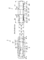
- FIG. 7 shows a comparison between the plan view structure of the male member 2 and the front view structure of the female member 3 viewed from the insertion direction.
- FIG. 8 shows a front view structure of the male member 2 viewed from the protruding direction on the pair of arms 22 side and a front view structure of the female member 3 viewed from the insertion direction.
- FIG. 9 shows the plan view structure of the male member 2 and the plan view structure of the female member 3 in comparison.
- the pair of arms 22 constituting the male member 2 has a width D1 from the arm locking portion 22S to the inner end larger than the opening width D2 in the short direction of the insertion port 3P of the female member 3. It is formed to be sufficiently large. For this reason, the pair of arms 22 has a shape in which the width of the distal end portion is larger than the opening width D2 in the short direction of the insertion port 3P in the plan view (D1> D2). According to such a configuration, the thickness direction (X direction in the example of FIG. 7) at the distal ends of the pair of arms 22 and the short direction (Y direction in the example of FIG. 7) at the insertion port 3P are different from each other.
- the outer inclined surface 22Io and the inner inclined surface 22Ii of the pair of arms 22 are inserted into the front side while the pair of arms 22 are being inserted into the insertion port 3P. It abuts on the edge 31p and the back side insertion edge 32p.
- each of the pair of arms 22 is stopped while being inserted into the insertion port 3P, and the male member 2 and the female member 3 are stopped. Is prevented from being engaged in a wrong manner.
- the front end of the pair of arms 22 constituting the male member 2 has a thickness D3 in a region where the locked portion 23 is formed, and a front side guide groove 36 and a back side guide groove 37 are formed. It is formed to be smaller than the opening width D4 in the short direction of the insertion port 3P in the region (D3 ⁇ D4).
- the distal ends of the pair of arms 22 have a thickness D3 in the region where the locked portion 23 is formed, and the short side of the insertion port 3P in the region where the front side guide groove 36 and the back side guide groove 37 are not formed. It is formed to be larger than the opening width D5 in the direction (D3> D5).
- the thickness D6 in the region where the locked portion 23 is not formed at the distal ends of the pair of arms 22 is the short direction of the insertion port 3P in the region where the front side guide groove 36 and the back side guide groove 37 are not formed. Is formed to be smaller than the opening width D5 at (D6 ⁇ D5).
- the front-side convex portion 23F and the back-side convex portion 23B have the front-side guide groove 36 and the back-side guide groove whose groove width gradually decreases in the insertion direction. Since the guide is guided to the locking edge 32 ⁇ / b> S while being in contact with 37, the pair of arms 22 are accurately guided to the engagement position with the female member 3.
- the front side guide groove 36 and the back side guide groove 37 in the insertion port 3P are formed.
- the front side convex portion 23F and the back side convex portion 23B come into contact with the front side insertion edge 31p and the back side insertion edge 32p.
- a pair of arm 22 is inserted in the position which does not connect to the latching edge 32S from the horizontal direction of the female member 3, and the incorrect assembly
- each of the pair of arms 22 has a width D ⁇ b> 1 from the arm locking portion 22 ⁇ / b> S that becomes the maximum width at the tip portion thereof to the inner end of the front side guide groove 36 and the back side guide groove 37. It is formed to be sufficiently larger than the maximum distance D7 in the left-right direction between the groove side surface and the dividing wall 38 (D1> D7).
- the maximum width D1 of the tip portions of the pair of arms 22 is such that the groove side surfaces of the guide grooves 36 and 37 extending from the insertion port 3P to the locking edge 32S formed on the open port 3D side, and the dividing wall 38 It is larger than any of the distances.
- the assembly of the male member 2 and the female member 3 is performed from a position shifted in a plane including the pair of arms 22, thereby assembling the arm for the second accommodation space Sl.
- the tip of the first arm 22r abuts against the dividing wall 38 in the middle thereof.
- the erroneous engagement between the male member 2 and the female member 3 is automatically stopped in the middle of the insertion, and erroneous assembly due to the displacement of the assembly position in the horizontal direction is suppressed.
- the pair of arms 22 is inserted in the insertion direction from the insertion port 3P in a defined manner so that the thickness direction at the distal ends of the pair of arms 22 and the short direction of the insertion port 3P coincide.
- the distal ends of the pair of arms 22 enter the female member 3 while the outer surface of the arms 22 is in sliding contact with the guide surface WPa.
- a pair of front side convex portions 23F projecting from the surface of the arm 22 are guided to the locking groove 36S along the front side insertion groove 36a.
- a pair of back side convex portions 23 ⁇ / b> B protruding from the back surface of the arm 22 is guided along the back side guide groove 37 to the opening 3 ⁇ / b> D.
- the thickness D3 of the distal end portion of the pair of arms 22 in the region where the locked portion 23 is formed is the region where the front side guide groove 36 and the back side guide groove 37 are formed in the short direction of the insertion port 3P.
- the opening width D4 is smaller than the opening width D4 and larger than the opening width D5 in the unformed region of the front side guide groove 36 and the back side guide groove 37 (D5 ⁇ D3 ⁇ D4).
- 23 guides each pair of arms 22 to the opening 3D while being in sliding contact with the groove side surfaces of the front guide groove 36 and the back guide groove 37.
- the outer inclined surface 22Io is guided to the opening 3D side while being in sliding contact with the guide surface WPa, whereby the pair of arms 22 is guided to the opening 3D along the outer inclined surface 22Io.
- the inner inclined surface 22Ii is guided to the opening 3D while being in sliding contact with the dividing wall 38, whereby the pair of arms 22 is guided to the opening 3D along the outer inclined surface 22Io.
- the pair of arms 22 is cooperated with the outer inclined surface 22Io and the inner inclined surface 22Ii, the guide grooves 36 and 37, and the dividing wall 38. The force which guides each of these in the insertion direction of the insertion port 3P will act. Thereby, each arm 22 smoothly moves to the engagement position with the female member 3 even though the width D1 of the distal end portion of the pair of arms 22 is larger than the opening width in the short direction of the insertion port 3P. Be guided.
- each of the pair of arms 22 has a shape that protrudes outward in the left-right direction at the arm locking portion 22S.
- the guide surface WPa in a pair of insertion side connection wall WP has a shape which aligns with the outer surface in the base end of a pair of arm 22. FIG. Therefore, when the pair of arms 22 is inserted into the female member 3, the outer surface of each of the pair of arms 22 protrudes outward from the guide surface WPa, so that the outer surface of the arm 22 is laterally moved by the guide surface WPa. It will be pushed closer to the center.
- the pair of arms 22 is bent most greatly toward the center in the left-right direction.
- the pushing of the guide surface WPa with respect to the outer surface of the arm 22 is released, and the bending in the pair of arms 22 follows the guidance of the front insertion groove 36a and the back guide groove 37. It becomes.
- the groove widths of the front-side insertion groove 36a and the back-side guide groove 37 are formed so as to narrow at a constant rate from the insertion port 3P toward the opening port 3D.
- the pair of arms 22 while the pair of arms 22 is inserted according to the guidance of the front side insertion groove 36a and the back side guide groove 37, the pair of arms 22 enters the female member 3 while being bent at a constant rate toward the center in the left-right direction. It becomes like this.
- the arm locking portion 22S passes through the guide surface WPa, the external force with respect to the arm 22 is temporarily increased. Therefore, the engagement between the arm locking portion 22S and the guide surface WPa causes a pair of forces. It is possible to temporarily fix the arm 22 to the female member 3.
- the front side convex portion 23F reaches the locking groove 36S, and the back side convex portion 23B reaches the opening 3D.
- the locking groove 36S is expanded from the front-side insertion groove 36a and the locking edge 32S is expanded from the back-side guide groove 37
- the pair of arms 22 bent toward the center in the left-right direction.
- they extend outward in the left-right direction according to the shape of the locking groove 36S and the shape of the locking edge 32S.
- the front-side convex portion 23F comes into contact with the groove side wall of the locking groove 36S, and the front-side convex portion 23F is difficult to move to the insertion port 3P side.
- the back side convex portion 23B comes into contact with the bottom edge of the locking edge 32S, and the back side convex portion 23B is difficult to move to the insertion port 3P side.
- the male member 2 is coupled to the female member 3.
- the pair of arms 22 is inserted from the insertion port 3P in the insertion direction by an unspecified method in which the thickness direction at the distal ends of the pair of arms 22 and the short direction of the insertion port 3P are different from each other. Then, the outer inclined surface 22Io and the inner inclined surface 22Ii at the tips of the pair of arms 22 are first brought into contact with the front-side insertion edge 31p and the back-side insertion edge 32p. Even if a force is further applied to insert the pair of arms 22 into the insertion port 3P, the width of the distal end portions of the pair of arms 22 is sufficiently larger than the opening width D2 in the short direction of the insertion port 3P. Since it has a large shape, the distal end portions of the pair of arms 22 are prevented from being inserted into the insertion port 3P. Thereby, it is suppressed that the male member 2 and the female member 3 are engaged in a wrong manner.
- the effects listed below can be obtained.
- the thickness of the tip portion is larger than the opening width D2 in the short direction of the insertion port 3P.
- the width of the tip is larger than the opening width D2 in the short direction of the insertion port. Therefore, when the male member 2 and the female member 3 are assembled in a defined manner in which the thickness direction at the tips of the pair of arms 22 matches the short direction at the insertion port, the pair of arms 22 are inserted into the insertion port 3P. As a result, the male member 2 and the female member 3 can be smoothly engaged.
- the opening in the short direction of the insertion port is formed. Since the width at the tip of each arm is larger than the width D2, it is structurally prevented that each arm 22 is inserted into the insertion port 3P, and the male member 2 and the female member 3 are engaged in an erroneous manner. Is suppressed. For this reason, it becomes possible to suppress erroneous assembly of the male member 2 and the female member 3 while facilitating the assembly of the male member 2 and the female member 3.
- a front-side insertion edge 31p and a back-side insertion edge 32p for guiding the pair of arms 22 to the engagement position with the female member 3 were formed from the opening edge of the insertion port 3P in the female member 3 to the opening 3D.
- the thickness D3 of each arm 22 including the locked portion 23 is smaller than the opening width D4 in the short direction of the insertion port 3P in the region where the front side guide groove 36 and the back side guide groove 37 are formed, and It was formed to be larger than the opening width D5 in the short direction in the region where the front side guide groove 36 and the back side guide groove 37 were not formed.
- the locked portion 23 is guided to the locking edge 32S while being in sliding contact with the groove side surfaces of the front side guide groove 36 and the back side guide groove 37. Accordingly, the pair of arms 22 are accurately guided to the engagement position with the female member 3, and the smooth assembly of the male member 2 and the female member 3 is realized.
- each arm 22 is inserted in the position which does not connect to the latching edge 32S from the horizontal direction of the female member 3, and the incorrect assembly
- the locked portion 23 is provided at the end where the pair of arms 22 face each other, and the maximum width D1 at the tip of each arm 22 is determined from the groove widths of the front side guide groove 36 and the back side guide groove 37 divided by the dividing wall 38. Also formed to be larger. For this reason, as one mode of misassembly of the male member 2 and the female member 3, when the pair of arms 22 is inserted into the insertion port 3P from a position shifted in a plane including the pair of arms 22, The arm 22l (22r) on the side different from the assembly arm 22r (221) abuts on the dividing wall 38.
- the thickness of the distal end portion of the arm 22 is determined at the locked portion 23, and the maximum width D1 at the distal end portion is determined based on the portion of the locked portion 23. For this reason, whether the assembly is in an unspecified manner such that the thickness direction at the distal ends of the pair of arms 22 and the short direction in the insertion port 3P are different from each other, or the assembly in a manner in which the assembly position in the horizontal direction is shifted, It is possible to reliably suppress the locked portion 23 projecting from the distal end portion of 22 from entering the inside of the female member 3.
- each arm 22 is smoothly moved to the engagement position with the female member 3 while the width D1 of the distal end portion of the pair of arms 22 is larger than the opening width D2 in the short direction of the insertion port 3P. Be guided by. Further, according to such a configuration, each arm 22 is guided by the front-side guide groove 36 and the back-side guide groove 37 through the locked portion 23, and each of the respective through the outer inclined surface 22Io by the guide surface WPa of the insertion port 3P. Due to the synergistic effect with the guidance of the arm 22, the male member 2 and the female member 3 can be engaged more accurately and smoothly.
- the pair of left and right arms 22r and 22l are connected by a bridge 25 which is a connecting member. For this reason, even if the male member 2 and the female member 3 are to be assembled in a manner different from the prescribed assembly position, the bridge 25 is brought into contact with the front-side insertion edge 31p and the back-side insertion edge 32p of the female member 3. Thereby, the incorrect assembly
- the said embodiment can also be implemented with the following aspects.
- the intermediate portion 25 b of the bridge 25 is formed to be curved in a convex shape toward the base portion 21 in the middle between the one arm 22 and the other arm 22, but is not limited thereto. Instead, it may be formed so as to curve in a convex shape toward the tips of the pair of arms 22. In this case, it is necessary to prevent the dividing wall 38 provided on the female member 3 from interfering with the bridge 25.
- the bridge 25 is disposed on the male member 2, the present invention is not limited thereto, and the bridge 25 may not be provided.
- a so-called center bar is provided that protrudes from the base 21 toward the insertion direction of the arm 22 and has a function of guiding the male member 2 when the arm 22 is inserted into the female member 3. You may do it. Even in this case, it is possible to make it difficult for an external force to increase the interval between the arms 22 to act on the arms 22.
- the center bar guide portion for guiding the center bar instead of the dividing wall 38 at the position where the dividing wall 38 was provided.
- the outer inclined surface 22Io and the inner inclined surface 22Ii tapering toward the tip in a plan view facing the plane including the pair of arms 22 were formed at the tip of each of the pair of arms 22.
- the present invention is not limited to this, and only the outer inclined surface 22Io or the inner inclined surface 22Ii may be formed at the tip of each of the pair of arms 22. Therefore, it is possible to simplify the configuration of the male member 2 while obtaining the effect according to the above (4).
- the shape of the tip of each of the pair of arms 22 is a semi-elliptical cross section having a predetermined curvature that tapers toward the tip in a plan view facing the plane including the pair of arms 22. Also good.
- the shape of the tip portions of the pair of arms 22 may be any shape that is flat and massive, and the tip portions of the pair of arms 22 in a plan view facing the plane that includes the pair of arms 22. It is sufficient that the thickness at is smaller than the opening width in the short direction of the insertion port 3P and the width at the tip of the pair of arms 22 is larger than the opening width in the short direction of the insertion port 3P.
- the present invention is not limited thereto, and the dividing wall 38 may be omitted.
- the engaged portion 23 is provided at the end where the pair of arms 22 face each other, and the maximum width D1 at the tip of each arm 22 is larger than the groove width D7 of the front side guide groove 36 and the back side guide groove 37 divided by the dividing wall 38. It formed so that it might become.
- the maximum width D1 at the tip of the arm 22 may be equal to or less than the groove widths of the front-side guide groove 36 and the back-side guide groove 37 divided by the dividing wall 38. Even in this case, it is possible to obtain the same effects as the above (1) and (2).
- the to-be-latched part 23 should just be provided in the position which can be engaged with the latching edge 32S among the front-end
- a front guide groove 36 formed so that the groove width narrows at a constant rate from the front insertion edge 31p toward the opening 3D was formed.
- a back-side guide groove 37 is formed on the inner surface of the back wall 32 of the female member 3 so that the groove width becomes narrower at a constant rate from the back-side insertion edge 32p toward the opening 3D.
- a groove in the front wall 31 or the back wall 32 of the female member 3 is formed on the front wall 31 or the back wall 32 of the female member 3 so that the groove width decreases with a predetermined curvature from the front insertion edge 31p and the back insertion edge 32p toward the opening 3D. It may be formed on the surface. Even in this case, it is possible to obtain the effect according to the above (2).
- a groove having a constant groove width extending linearly from the front insertion edge 31p and the back insertion edge 32p toward the opening 3D is formed on the inner surface of the front wall 31 or the rear wall 32 of the female member 3. Also good.
- the groove formed on the inner surface of the front wall 31 or the back wall 32 of the female member 3 is the engagement of the locked portion 23 formed in the thickness direction of the distal end portion of the pair of arms 22 from the insertion port 3P. Any shape that can be guided to the stop edge 32S is acceptable.
- the thickness D3 of each arm 22 including the locked portion 23 of the pair of arms 22 is larger than the opening width D4 in the short direction of the insertion port 3P in the region where the front side guide groove 36 and the back side guide groove 37 are formed. And the opening width D5 in the short direction in the region where the front side guide groove 36 and the back side guide groove 37 are not formed is formed.
- the thickness D3 of each arm 22 including the locked portion 23 is a pair of arms 22 in a prescribed manner in which the thickness direction at the distal ends of the pair of arms 22 and the short direction at the insertion port 3P match. Any thickness may be used as long as the arm 22 can be inserted into the insertion port 3P. Even in this case, it is possible to obtain the same effect as the above-mentioned (1).
- the base end positioning rib 27 or the front end positioning rib 28 is omitted, it is possible to obtain the same effects as the above (1) to (5).
- the convex rib is formed on the inner surface of the female member 3 and the male member 2 is connected to the female member 3, the pair of arms are pressed against the convex rib. Even if the positioning rib 28 is omitted, rattling of the male member 2 can be reduced.
- the locking edge 32S in the opening 3D is composed of a bottom edge extending in the left-right direction and a side edge extending in the insertion direction.
- the locking edge 32S may be formed so as to be convex in the insertion direction of the arm 22 or the removal direction of the arm 22.
- a front convex portion 23F is formed near the front end of the pair of arms 22, and a back convex portion 23B is formed near the rear end of the pair of arms 22.
- a configuration in which the engagement portion between the male member 2 and the female member 3 is limited to the front side convex portion 23F and the locking groove 36S that is, a configuration in which the back side convex portion 23B is omitted. If it is such a structure, it is also possible to omit the back side guide groove 37 other than the back side convex part 23B. Therefore, it is possible to simplify the configuration of the male member 2 and the female member 3 while obtaining the effect according to the above (1).
Abstract
Disclosed is a buckle which is provided with a male member having a pair of arms which have flat, enlarged tip ends, and a flat, cylindrical female member having, at one end of the cylindrical shape, an insertion opening which is a flat opening into which the pair of arms are inserted. When seen in plan view facing the plane including the pair of arms, the pair of arms have a shape in which the thickness at the tip ends is less than the width of the insertion opening in the short direction, and the width at the tip ends is greater than the width of the insertion opening in the short direction.
Description
本発明は、雌部材に雄部材が着脱自在に連結するバックルに関する。
The present invention relates to a buckle in which a male member is detachably connected to a female member.
従来から、例えば特許文献1に記載のように、雄部材と雌部材とから構成されるバックルが知られている。
特許文献1に記載の雄部材には、先端に係合部を有した互いに面対称な形状である一対のアームが、基部から延びるように設けられている。また、各アームの中央には、直線状のセンターバーが、基部から延びるように設けられている。 Conventionally, as described inPatent Document 1, for example, a buckle including a male member and a female member is known.
The male member described inPatent Literature 1 is provided with a pair of arms having an engaging portion at the tip and having a plane-symmetric shape extending from the base. In addition, a linear center bar is provided at the center of each arm so as to extend from the base.
特許文献1に記載の雄部材には、先端に係合部を有した互いに面対称な形状である一対のアームが、基部から延びるように設けられている。また、各アームの中央には、直線状のセンターバーが、基部から延びるように設けられている。 Conventionally, as described in
The male member described in
一方、雌部材には、一対のアームが挿入される挿入口を有した扁平筒状の収容部が、上記一対のアーム及び上記センターバーが内部に収容されるように設けられている。また、この収容部の中央には、上記センターバーが収容される空間を形成する仕切り片が設けられている。また、雌部材の収容部における内側面には、雄部材の係合部に係合される係止凸部が形成されている。
On the other hand, the female member is provided with a flat cylindrical housing portion having an insertion port into which the pair of arms are inserted so that the pair of arms and the center bar are housed therein. A partition piece that forms a space in which the center bar is accommodated is provided at the center of the accommodation portion. Moreover, the latching convex part engaged with the engaging part of a male member is formed in the inner surface in the accommodating part of a female member.
このように構成されたバックルにおける連結動作では、まず、一対のアームが並ぶ方向と挿入口の長手方向とが一致するように雄部材と雌部材とが対向し、この状態から一対のアームが挿入口に差し込まれる。そして、一対のアームが収容部の内側面に案内されるとともに、センターバーが仕切り片に案内されることにより、雌部材の係止凸部に雄部材の係合部が係合されるようになる。これにより、雄部材の収容部に雌部材のアームが的確に案内され、雌部材に雄部材が誤った態様で挿入される、いわば誤組み付けが抑制されるようになる。
In the connecting operation of the buckle configured as described above, first, the male member and the female member face each other so that the direction in which the pair of arms are aligned and the longitudinal direction of the insertion port coincide, and the pair of arms is inserted from this state. It is inserted into the mouth. And while a pair of arms are guided to the inner surface of the accommodating part and the center bar is guided to the partition piece, the engaging part of the male member is engaged with the engaging convex part of the female member. Become. Thereby, the arm of the female member is accurately guided to the housing portion of the male member, and the male member is inserted into the female member in a wrong manner, that is, erroneous assembly is suppressed.
ところで、特許文献1に記載のバックルにあっては上述のように、一対のアームが並ぶ方向と挿入口の長手方向とが一致する状態でアームの先端が収容部に挿入されることが前提とされている。すなわち、上記各アームや各アームを収容する収容部は、上述した状態で差し込み動作が行われることを前提として形成されたものでしかない。このため、一対のアームが並ぶ方向と挿入口の長手方向とが互いに異なる状態から雌部材の差し込み動作が行われる場合には、規定された組み付け位置とは異なる態様で雌部材の収容部に雄部材のアームが組み付けられることとなってしまう。この結果、雄部材と雌部材とにおける規定の連結構造をバックルにおいて担保することができず、バックルに求められる連結機能や分離機能を発揮することができなくなる虞があった。
By the way, in the buckle described in Patent Document 1, as described above, it is assumed that the tip of the arm is inserted into the accommodating portion in a state where the direction in which the pair of arms are aligned and the longitudinal direction of the insertion port coincide. Has been. In other words, the arms and the accommodating portions for accommodating the arms are only formed on the assumption that the insertion operation is performed in the above-described state. For this reason, when the female member is inserted from a state in which the direction in which the pair of arms are arranged and the longitudinal direction of the insertion opening are different from each other, the male member is accommodated in the female member housing portion in a manner different from the specified assembly position. The arm of a member will be assembled | attached. As a result, there is a possibility that the prescribed connecting structure between the male member and the female member cannot be secured in the buckle, and the connecting function and separating function required for the buckle cannot be exhibited.
なお、このような課題は、雄部材としてセンターバーを有さない構造であっても、概ね共通したものとなっている。
本発明は、こうした実情に鑑みてなされたものであり、雄部材と雌部材との組み付けの円滑化を図りつつ、雄部材と雌部材との誤組み付けを抑制することのできるバックルを提供することを目的とする。 Such a problem is generally common even in a structure having no center bar as a male member.
The present invention has been made in view of such circumstances, and provides a buckle capable of suppressing erroneous assembly between a male member and a female member while facilitating the assembly of the male member and the female member. With the goal.
こうした目的を達成するため、本発明は、扁平膨大状の先端部を有した一対のアームを有する雄部材と、前記一対のアームが挿入される扁平開口である挿入口を一方の筒端に有した扁平筒状の雌部材とを備えるバックルにおいて、前記一対のアームは、前記一対のアームが含まれる平面に対向する平面視にて、当該一対のアームの先端部における厚みが前記挿入口の短手方向における開口幅よりも小さく、かつ、当該一対のアームの先端部における幅が前記挿入口の短手方向における開口幅よりも大きい形状を有することを要旨とする。
In order to achieve such an object, the present invention has a male member having a pair of arms having a flat and massive tip portion and an insertion port which is a flat opening into which the pair of arms are inserted at one end of the cylinder. In the buckle provided with the flat cylindrical female member, the pair of arms has a short thickness of the insertion opening at a tip portion of the pair of arms in a plan view facing a plane including the pair of arms. The gist of the invention is that it has a shape that is smaller than the opening width in the hand direction and that the width at the distal end portion of the pair of arms is larger than the opening width in the short direction of the insertion opening.
本発明のバックルによれば、挿入口に挿入される一対のアームは、一対のアームが含まれる平面に対向する平面視において、その先端部の厚みが挿入口の短手方向における開口幅よりも小さく、かつ、同先端部の幅が挿入口の短手方向における開口幅よりも大きい形状を有する。それゆえに、一対のアームの先端における厚み方向と挿入口における短手方向とが一致するような規定の方式で雄部材と雌部材とが組み付けられる際には、一対のアームが挿入口に挿入されることで雄部材と雌部材との係合を円滑に行なうことができる。一方、一対のアームの先端における厚み方向と挿入口における短手方向とが互いに異なるような規定外の方式で雄部材と雌部材とが組み付けられる際には、挿入口の短手方向における開口幅よりも各アームの先端部における幅が大きいために、構造上、各アームが挿入口に挿入されることが抑止される。すなわち、雄部材と雌部材とが誤った態様で係合されることが抑制される。このため、雄部材と雌部材との組み付けの円滑化を図りつつ、雄部材と雌部材との誤組み付けを抑制することができるようになる。
According to the buckle of the present invention, the pair of arms to be inserted into the insertion slot has a tip portion whose thickness is smaller than the opening width in the short direction of the insertion slot in a plan view facing a plane including the pair of arms. The shape is small and the width of the tip is larger than the opening width in the short direction of the insertion slot. Therefore, when the male member and the female member are assembled in a defined manner such that the thickness direction at the tips of the pair of arms coincides with the short direction at the insertion port, the pair of arms are inserted into the insertion port. Thus, the engagement between the male member and the female member can be performed smoothly. On the other hand, when the male member and the female member are assembled in an unspecified manner such that the thickness direction at the tips of the pair of arms and the short direction at the insertion port are different from each other, the opening width in the short direction of the insertion port. Since the width at the tip portion of each arm is larger than that, it is structurally prevented that each arm is inserted into the insertion port. That is, it is suppressed that the male member and the female member are engaged in a wrong manner. For this reason, it becomes possible to suppress erroneous assembly of the male member and the female member while facilitating the assembly of the male member and the female member.
好ましくは、本発明では、前記雄部材は、前記一対のアームの厚み方向に突出する被係止部を前記先端部に有し、前記雌部材は、前記一対のアームの厚み方向に互いに対向した上板と下板とを有し、当該上板もしくは下板の少なくとも一方の内表面には、前記被係止部との係合によって前記雄部材が該雌部材から脱離することを係止する係止部と、前記挿入口から前記係止部まで前記被係止部を案内する案内溝とが形成され、前記一対のアームは、前記一対のアームが含まれる平面に対向する平面視にて、前記被係止部が形成された領域における前記先端部の厚みが、前記案内溝が形成された領域での前記挿入口の短手方向における開口幅よりも小さく、かつ、前記案内溝の非形成領域での前記挿入口の短手方向における開口幅よりも大きい形状を有することを要旨とする。
Preferably, in the present invention, the male member has a locked portion protruding in the thickness direction of the pair of arms at the distal end portion, and the female member is opposed to each other in the thickness direction of the pair of arms. It has an upper plate and a lower plate, and the inner surface of at least one of the upper plate and the lower plate is locked against the detachment of the male member from the female member by engagement with the locked portion. And a guide groove that guides the locked portion from the insertion port to the locking portion, and the pair of arms are in a plan view facing a plane including the pair of arms. The thickness of the tip in the region where the locked portion is formed is smaller than the opening width in the short direction of the insertion port in the region where the guide groove is formed, and the guide groove Larger than the opening width in the short direction of the insertion opening in the non-forming region And summarized in that a shape.
上記構成によれば、雌部材における挿入口の開口縁には、一対のアームを雌部材との係合位置まで案内する案内溝が形成される。また、被係止部を含んだ各アームの厚みは、案内溝が形成された領域での上記短手方向における開口幅よりも小さく、且つ案内溝の非形成領域での上記短手方向における開口幅よりも大きい。このため、雄部材と雌部材との組み付け時には、被係止部が案内溝に当接されながら上記係止部まで案内される。これにより、一対のアームが雌部材との係合位置まで的確に案内されることとなり、雄部材と雌部材との円滑な組み付けが実現される。
According to the above configuration, the guide groove for guiding the pair of arms to the engagement position with the female member is formed at the opening edge of the insertion opening in the female member. In addition, the thickness of each arm including the locked portion is smaller than the opening width in the short direction in the region where the guide groove is formed, and the opening in the short direction in the region where the guide groove is not formed. Greater than width. For this reason, when the male member and the female member are assembled, the locked portion is guided to the locking portion while being in contact with the guide groove. Accordingly, the pair of arms are accurately guided to the engagement position with the female member, and the smooth assembly of the male member and the female member is realized.
また、挿入口における案内溝が形成されていない領域では、挿入口の開口幅よりも被係止部を含めた各アームの厚みが大きくなる。このため、雌部材の水平方向から係止部に連通しない位置に各アームが挿入されることが抑制されることとなり、雄部材と雌部材との誤組み付けが好適に抑制されることとなる。
Also, in the region where the guide groove is not formed in the insertion port, the thickness of each arm including the locked portion is larger than the opening width of the insertion port. For this reason, it will be suppressed that each arm is inserted in the position which does not communicate with a latching | locking part from the horizontal direction of a female member, and the incorrect assembly | attachment of a male member and a female member will be suppressed suitably.
好ましくは、本発明では、前記雌部材は、前記挿入口の長手方向に該挿入口を2分割する分割壁を有し、前記被係止部は、前記一対のアームにおける互いに向かい合う端にそれぞれ設けられたものであり、前記案内溝は、前記一対のアームの各々に設けられた一対の前記被係止部の各々を前記挿入口から前記係止部まで延びる溝側面に沿って案内するものであり、前記一対のアームの各々における先端部の最大幅は、前記案内溝の溝側面と前記分割壁との距離よりも大きいことを要旨とする。
Preferably, in the present invention, the female member has a dividing wall that divides the insertion port into two in the longitudinal direction of the insertion port, and the locked portions are provided at opposite ends of the pair of arms, respectively. The guide groove guides each of the pair of locked portions provided in each of the pair of arms along a groove side surface extending from the insertion port to the locking portion. The gist of the present invention is that the maximum width of the tip portion of each of the pair of arms is larger than the distance between the groove side surface of the guide groove and the dividing wall.
上記構成によれば、一対のアームが向かい合う端に被係止部が設けられるとともに、一対のアームの先端における最大幅が上記分割壁により分割された各々の案内溝の溝幅よりも大きくなる。雄部材と雌部材とが誤って組み付けられる組み付けの態様には、一対のアームが含まれる平面においてずれた位置から各部材の組み付けが行われ、これに起因して、上記分割された挿入口に規定の組み付けアームとは異なる側のアームが挿入されるものがある。ただし、このような組み付けが行われる場合であっても、上述した構成によれば、規定の組み付けアームとは異なる側のアームが分割壁に当接する、あるいは該アームの被係止部が案内溝の非形成領域に当接するため、雄部材と雌部材との誤った態様での係合が挿入の途中で自ずと停止される。これにより、特に水平方向における組み付け位置のずれに起因する誤組み付けが好適に抑制されるようになる。しかも上述した構成によれば、先端部の厚みが被係止部において特に大きく、その被係止部の部位に基づき、先端における最大幅が規定される。そのため、一対のアームの先端部における厚み方向と挿入口における短手方向とが互いに異なるような規定外の方式の組み付けであれ、また水平方向における組み付け位置がずれた方式の組み付けであれ、先端部に突設された被係止部が雌部材の内部に入り込むことを確実に抑えることが可能である。
According to the above configuration, the locked portion is provided at the end where the pair of arms face each other, and the maximum width at the tip of the pair of arms is larger than the width of each guide groove divided by the dividing wall. In the assembly mode in which the male member and the female member are assembled by mistake, each member is assembled from a position shifted in the plane including the pair of arms, and as a result, the divided insertion opening is inserted into the divided insertion port. In some cases, an arm on a different side from the prescribed assembly arm is inserted. However, even when such assembly is performed, according to the configuration described above, the arm on the side different from the prescribed assembly arm abuts against the dividing wall, or the locked portion of the arm is a guide groove. Therefore, the engagement of the male member and the female member in the wrong manner is automatically stopped during the insertion. Thereby, the erroneous assembly resulting from the shift of the assembly position especially in the horizontal direction is suitably suppressed. Moreover, according to the configuration described above, the thickness of the tip portion is particularly large at the locked portion, and the maximum width at the tip is defined based on the portion of the locked portion. For this reason, the tip portion of the pair of arms may be attached in an unspecified manner such that the thickness direction at the tip portion of the pair of arms is different from the short direction in the insertion port, or in a manner in which the assembly position is shifted in the horizontal direction. It is possible to reliably suppress the locked portion projecting from the inside of the female member.
好ましくは、本発明では、前記一対のアームの各々の先端部は、前記一対のアームが含まれる平面に対向する平面視にて先端に向かって先細りした傾斜面を有することを要旨とする。
Preferably, the gist of the present invention is that each of the tip portions of the pair of arms has an inclined surface that is tapered toward the tip in a plan view opposite to a plane including the pair of arms.
上記構成によれば、先端に向かって先細りした先端部が上記挿入口の開口縁に摺接しながら一対のアームが雌部材に挿入されると、先細りした傾斜面の傾斜に倣って、一対のアームが雌部材の内部へ挿入される。また、先端に向かって先細りした先端部が上記分割壁に摺接しながら一対のアームが雌部材に挿入されると、これもまた先細りした傾斜面の傾斜に倣って、一対のアームの各々が本来位置するべき係合位置へ案内される。これにより、先端部の幅が挿入口の短手方向における開口幅よりも大きい形状としつつも、雄部材と雌部材との組み付けにかかるさらなる円滑化が図られるようになる。
According to the above configuration, when the pair of arms are inserted into the female member while the distal end portion tapered toward the distal end is in sliding contact with the opening edge of the insertion port, the pair of arms follows the inclination of the tapered inclined surface. Is inserted into the female member. Further, when the pair of arms is inserted into the female member while the tip portion tapered toward the tip is in sliding contact with the dividing wall, each of the pair of arms is inherently following the inclination of the tapered inclined surface. Guided to the engagement position to be located. Thereby, further smoothing for the assembly of the male member and the female member can be achieved while the width of the distal end portion is larger than the opening width in the short direction of the insertion opening.
好ましくは、本発明では、前記雄部材は、前記一対のアームを接続する接続部材を備えることを要旨とする。
上記構成によれば、上記接続部材により一対のアームが接続される。このため、雄部材と雌部材とが規定の組み付け位置とは異なる態様で組み付けられようとしても、接続部材が雌部材の一方の筒端に当接される。これにより、雄部材と雌部材との誤組み付けをより確実に抑制することができる。また上記構成によれば、上記一対のアームが接続部材により支持される構造となる。これにより、雄部材としての構造上の安定化が図られるようになる。 Preferably, in the present invention, the male member includes a connection member that connects the pair of arms.
According to the said structure, a pair of arm is connected by the said connection member. For this reason, even if the male member and the female member are to be assembled in a manner different from the prescribed assembly position, the connecting member is brought into contact with one cylindrical end of the female member. Thereby, the incorrect assembly | attachment with a male member and a female member can be suppressed more reliably. According to the above configuration, the pair of arms are supported by the connection member. Thereby, the structural stability as a male member comes to be achieved.
以下、本発明に係るバックルの一実施の形態について図を参照して説明する。まず、バックル1の全体構造について図1及び図2を参照して説明する。
バックル1の雄部材2における基部21には、可撓性を有した左右一対の第1アーム22r及び第2アーム22lによって構成されるアーム22が該基部21から延びるように形成されている。またバックル1の雌部材3は、扁平した筒状に形成され、扁平方向に広がる互いに対向した上板としての表壁31と下板としての裏壁32とを有している。この雌部材3における一方の筒端(図1及び図2における右側の筒端)には、一対のアーム22が挿入される挿入口3Pが形成され、また他方の筒端には、挿入口3Pに対向した開放口3Dが形成されている。以下、挿入口3Pから開放口3Dに向けた方向を挿入方向とし、一対のアーム22が並ぶ方向を左右方向する。またバックル1における表壁31側を表側とし、バックル1における裏壁32側を裏側とする。 Hereinafter, an embodiment of a buckle according to the present invention will be described with reference to the drawings. First, the overall structure of thebuckle 1 will be described with reference to FIGS. 1 and 2.
On thebase portion 21 of the male member 2 of the buckle 1, an arm 22 constituted by a pair of left and right first arms 22 r and second arms 221 having flexibility is formed so as to extend from the base portion 21. The female member 3 of the buckle 1 is formed in a flat cylindrical shape, and has a front wall 31 as an upper plate and a back wall 32 as a lower plate that face each other and spread in the flat direction. An insertion port 3P into which the pair of arms 22 are inserted is formed at one cylindrical end (the right cylindrical end in FIGS. 1 and 2) of the female member 3, and the insertion port 3P is formed at the other cylindrical end. An open port 3D is formed so as to face the surface. Hereinafter, the direction from the insertion port 3P toward the opening 3D is defined as the insertion direction, and the direction in which the pair of arms 22 are aligned is defined as the left-right direction. The front wall 31 side of the buckle 1 is the front side, and the back wall 32 side of the buckle 1 is the back side.
バックル1の雄部材2における基部21には、可撓性を有した左右一対の第1アーム22r及び第2アーム22lによって構成されるアーム22が該基部21から延びるように形成されている。またバックル1の雌部材3は、扁平した筒状に形成され、扁平方向に広がる互いに対向した上板としての表壁31と下板としての裏壁32とを有している。この雌部材3における一方の筒端(図1及び図2における右側の筒端)には、一対のアーム22が挿入される挿入口3Pが形成され、また他方の筒端には、挿入口3Pに対向した開放口3Dが形成されている。以下、挿入口3Pから開放口3Dに向けた方向を挿入方向とし、一対のアーム22が並ぶ方向を左右方向する。またバックル1における表壁31側を表側とし、バックル1における裏壁32側を裏側とする。 Hereinafter, an embodiment of a buckle according to the present invention will be described with reference to the drawings. First, the overall structure of the
On the
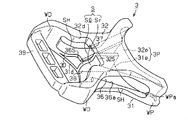
図3及び図4に示されるように、雄部材2が有する一対のアーム22の各々は、該一対のアーム22が含まれる平面と対向する平面視において、先端寄りが膨大するかたちで扁平状に形成されている。また一対のアーム22の先端部は、該アーム22が含まれる平面と対向する平面視において、先端に向かって先細りした傾斜面22Iを有している。傾斜面22Iは、左右方向の内側に形成された内側傾斜面22Iiと、左右方向の外側に形成された外側傾斜面22Ioとによって構成されている。また右側のアーム22における右側外表面、及び左側のアーム22における左側外表面は、同じく一対のアーム22が含まれる平面と対向する平面視において、その挿入方向における中間部分であるアーム係止部22Sが左右方向の外側に張り出すように湾曲した形状を有している。
As shown in FIGS. 3 and 4, each of the pair of arms 22 included in the male member 2 is flattened in a plan view in which the tip end is enormous in plan view opposite to the plane including the pair of arms 22. Is formed. Further, the distal ends of the pair of arms 22 have an inclined surface 22I that tapers toward the distal end in a plan view facing the plane in which the arms 22 are included. The inclined surface 22I includes an inner inclined surface 22Ii formed on the inner side in the left-right direction and an outer inclined surface 22Io formed on the outer side in the left-right direction. The right outer surface of the right arm 22 and the left outer surface of the left arm 22 are arm locking portions 22S that are intermediate portions in the insertion direction in a plan view facing the plane in which the pair of arms 22 are included. Has a curved shape so as to project outward in the left-right direction.
上述のような外形を有する一対のアーム22の先端寄りには、該アーム22の厚み方向に突出する被係止部23がそれぞれ形成されている。被係止部23は、アーム22が向かい合う端にあって、該アーム22の表面に突設された第一の被係止凸部として一対の表側凸部23Fと、アーム22の裏面に突設された第二の被係止凸部としての裏側凸部23Bとによって構成されている。また一対のアーム22の先端寄りには、断面が菱形状を成してアーム22が延びる方向(上記挿入方向)に延びるアーム孔24が該アーム22の表側から裏側までを貫通するように形成されている。そして一対のアーム22が含まれる平面に対して面対称となるように、すなわち表側から見た一対のアーム22の構造と裏側から見た一対のアーム22の構造とが同一となるように、雄部材2は形成されている。なお、上述したようなアーム孔24が一対のアーム22の各々に設けられているため、アーム22の強度が確保されつつ、雄部材2が例えば樹脂成型によって形成される際には、ひけが発生してしまうことを回避することが可能である。
Near the tip of the pair of arms 22 having the above-described outer shape, locked portions 23 protruding in the thickness direction of the arms 22 are formed. The locked portion 23 is located at the end where the arm 22 faces and a pair of front side convex portions 23F as the first locked convex portion protruding from the surface of the arm 22 and the rear surface of the arm 22 It is comprised by the back side convex part 23B as the made 2nd to-be-latched convex part. Further, near the tip of the pair of arms 22, an arm hole 24 is formed so as to penetrate from the front side to the back side of the arm 22 in a rhombus section and extending in the direction in which the arm 22 extends (the insertion direction). ing. The male arm 22 is configured so as to be plane-symmetric with respect to the plane including the pair of arms 22, that is, the structure of the pair of arms 22 viewed from the front side is the same as the structure of the pair of arms 22 viewed from the back side. The member 2 is formed. In addition, since the arm hole 24 as described above is provided in each of the pair of arms 22, sink marks are generated when the male member 2 is formed by, for example, resin molding while ensuring the strength of the arms 22. It is possible to avoid this.
ちなみに、アーム22の基端寄りにおける表面及び裏面には、それぞれ基端位置決めリブ27が配設され、またアーム22の先端寄りにおける表面及び裏面には、それぞれ先端位置決めリブ28が配設されている。このような位置決めリブが形成された構成では、雌部材3に雄部材2が連結される際に、一対のアーム22の外表面と雌部材3の内表面との距離が、基端位置決めリブ27及び先端位置決めリブ28が形成された部位、すなわち一対のアーム22における基端と先端とで特に短くなる。そのため、雌部材3に雄部材2が連結された状態では、バックル1の厚み方向において、雌部材3に対する雄部材2の位置ずれ(がたつき)を抑えることが可能である。
Incidentally, proximal end positioning ribs 27 are disposed on the front and rear surfaces of the arm 22 near the proximal end, and distal end positioning ribs 28 are disposed on the front and rear surfaces of the arm 22 near the distal end. . In the configuration in which such positioning ribs are formed, when the male member 2 is connected to the female member 3, the distance between the outer surface of the pair of arms 22 and the inner surface of the female member 3 is determined by the proximal end positioning rib 27. And it becomes especially short in the site | part in which the front-end | positioning positioning rib 28 was formed, ie, the base end and front-end | tip in a pair of arms 22. FIG. Therefore, in a state where the male member 2 is connected to the female member 3, it is possible to suppress displacement (rattle) of the male member 2 with respect to the female member 3 in the thickness direction of the buckle 1.
一対のアーム22において互いに対向する内側面には、一対のアーム22を互いに繋ぐ可撓性を有した帯状の接続部材としてのブリッジ25が、アーム22の先端寄りであって、かつ被係止部23よりも基端寄りに形成されている。このブリッジ25における両端部25aの各々は、一方のアーム22から他方のアーム22に向けて延びるように形成されている。詳述すると、一方のアーム22に接続されるブリッジ25の端部25aは、該アーム22に外力が加えられていない状態(図3及び図4に示される状態)で、該アーム22の基端を中心として該アーム22とブリッジ25との接続部が描く円弧Cの接線方向と一致するように形成されている。またブリッジ25における中間部25bは、一方のアーム22と他方のアーム22との中間において基部21側に湾曲するように形成されている。このため、一対のアーム22に対する過度の外力が該一対のアーム22の間隔を広げる方向に作用する場合であっても、一対のアーム22の各々とブリッジ25との接続部にはせん断力が発生し難くなる。なお、基部21に対してアーム22とは反対側には、バックル1によって締結されるベルトがその長さを可変にするように保持されるベルト保持部26が架設されている。
On the inner side surfaces of the pair of arms 22 facing each other, a bridge 25 as a flexible band-shaped connecting member that connects the pair of arms 22 to each other is near the tip of the arm 22 and is to be locked. It is formed closer to the base end than 23. Each of the both ends 25 a of the bridge 25 is formed to extend from one arm 22 toward the other arm 22. More specifically, the end 25a of the bridge 25 connected to one arm 22 is in a state where no external force is applied to the arm 22 (the state shown in FIGS. 3 and 4), and the base end of the arm 22 Is formed so as to coincide with the tangential direction of the arc C drawn by the connecting portion between the arm 22 and the bridge 25. The intermediate portion 25 b of the bridge 25 is formed so as to bend toward the base portion 21 in the middle between the one arm 22 and the other arm 22. For this reason, even if an excessive external force acting on the pair of arms 22 acts in the direction of widening the distance between the pair of arms 22, a shearing force is generated at the connection portion between each of the pair of arms 22 and the bridge 25. It becomes difficult to do. A belt holding portion 26 is provided on the opposite side of the base portion 21 from the arm 22 so that the belt fastened by the buckle 1 is held so that its length can be varied.
図5及び図6に示されるように、雌部材3における表壁31は、表側から見てX字状を成すとともに、内側に湾曲した四つの縁によって囲まれている。また雌部材3における裏壁32は、裏側から見てX字状を成すとともに、内側に湾曲した四つの縁によって囲まれている。これら雌部材3を構成する表壁31の四隅と裏壁32の四隅において、挿入口3P寄りの一対の挿入側連結壁WPと開放口寄りの一対の開放側連結壁WDとによって表壁31と裏壁32とが互いに連結されている。さらに一対の挿入側連結壁WPにおける内表面には、雌部材3に雄部材2が連結された状態で一対のアーム22の基端における外表面と整合するようなガイド面WPaが形成されている。そして雌部材3の挿入方向における一方の筒端には、挿入方向と平行な方向から見て矩形状の挿入口3Pが、上記表壁31、裏壁32、及び挿入側連結壁WPによってその四辺を縁取られるかたちに形成されている。また雌部材3の挿入方向における他方の筒端には、挿入方向と平行な方向から見て矩形状の開放口3Dが、上記表壁31、裏壁32、及び開放側連結壁WDによってその四辺を縁取られるかたちに形成されている。
5 and 6, the front wall 31 of the female member 3 has an X shape when viewed from the front side and is surrounded by four edges curved inward. The back wall 32 of the female member 3 has an X shape when viewed from the back side and is surrounded by four edges curved inward. At the four corners of the front wall 31 and the back wall 32 constituting the female member 3, the pair of insertion side connection walls WP near the insertion port 3P and the pair of open side connection walls WD near the opening port are connected to the front wall 31. The back wall 32 is connected to each other. Furthermore, guide surfaces WPa are formed on the inner surfaces of the pair of insertion-side connecting walls WP so as to align with the outer surfaces of the base ends of the pair of arms 22 in a state where the male member 2 is connected to the female member 3. . A rectangular insertion port 3P as viewed from a direction parallel to the insertion direction is provided at one end of the cylinder in the insertion direction of the female member 3 by the front wall 31, the back wall 32, and the insertion side connecting wall WP. It is formed in the form of being framed. Further, at the other cylinder end in the insertion direction of the female member 3, a rectangular opening 3 </ b> D as viewed from a direction parallel to the insertion direction has four sides thereof by the front wall 31, the back wall 32, and the opening-side connecting wall WD. It is formed in the form of being framed.
雌部材3が有する挿入口3Pの開口縁には、表壁31において挿入口3P寄りの縁である表側挿入縁31pと、裏壁32において挿入口3P寄りの縁である裏側挿入縁32pとが含まれている。
The opening edge of the insertion port 3P of the female member 3 includes a front-side insertion edge 31p that is an edge near the insertion port 3P on the front wall 31 and a back-side insertion edge 32p that is an edge near the insertion port 3P on the back wall 32. include.
これら表側挿入縁31p及び裏側挿入縁32pは、それぞれ開放口3Dに向けて張り出すように湾曲した形状を有して、表壁31の外表面及び裏壁32の外表面と対向する平面視において互いに重なるように形成されている。また表壁31の外表面及び裏壁32の外表面と対向する平面視においては、表側挿入縁31p及び表側開口縁31dが一対のアーム22の外形に倣うように、表壁31及び裏壁32の外形が形成されている。そして雌部材3に雄部材2が連結された状態では、上記一対のアーム22が含まれる平面に対して面対称となるように、挿入口3Pが形成されている。このような構成によれば、雌部材3に雄部材2が連結された状態において、雄部材2と雌部材3との機能的な一体感に基づく美観が高められる。また、このような構成からなる挿入口3Pによれば、雌部材3における挿入口3Pと一対のアーム22における先端部とが互いに面対称であるため、雌部材3に雄部材2が連結される際に、一対のアーム22が挿入口3Pに挿入されやすくなる。
Each of the front-side insertion edge 31p and the back-side insertion edge 32p has a curved shape so as to project toward the opening 3D, and in plan view facing the outer surface of the front wall 31 and the outer surface of the back wall 32 They are formed so as to overlap each other. Further, in a plan view facing the outer surface of the front wall 31 and the outer surface of the back wall 32, the front wall 31 and the back wall 32 so that the front-side insertion edge 31 p and the front-side opening edge 31 d follow the outer shape of the pair of arms 22. The outer shape is formed. In the state where the male member 2 is connected to the female member 3, the insertion port 3P is formed so as to be plane-symmetric with respect to the plane including the pair of arms 22. According to such a configuration, in the state where the male member 2 is connected to the female member 3, the aesthetic appearance based on the functional unity between the male member 2 and the female member 3 is enhanced. In addition, according to the insertion port 3P having such a configuration, the insertion member 3P in the female member 3 and the tip portions of the pair of arms 22 are symmetrical with each other, so that the male member 2 is coupled to the female member 3. At this time, the pair of arms 22 are easily inserted into the insertion port 3P.
一方、雌部材3が有する開放口3Dの開口縁には、表壁31において開放口3D寄りの縁である表側開口縁31dと、裏壁32において開放口3D寄りの縁である裏側開口縁32dとが含まれている。そして雌部材3に雄部材2が連結された状態では、上記一対のアーム22が含まれる平面に対して非対称となるように、開放口3Dが形成されている。
On the other hand, the opening edge of the opening 3D of the female member 3 includes a front opening 31d that is the edge near the opening 3D on the front wall 31 and a back opening 32d that is the edge near the opening 3D on the back wall 32. And are included. In the state where the male member 2 is connected to the female member 3, the opening 3D is formed so as to be asymmetric with respect to the plane including the pair of arms 22.
詳述すると、上記表側開口縁31dは、挿入口3Pに向けて張り出すように湾曲した形状を有している。また表壁31の外表面と対向する平面視においては、表側挿入縁31p及び表側開口縁31dが一対のアーム22の外形に倣うように、表壁31の外形が形成されている。そして雌部材3に雄部材2が連結された状態では、表壁31の外表面と対向する平面視において、開放口3Dから上記一対のアーム22が露出しないように、表壁31が形成されている(図1及び図2参照)。このような構成によれば、上記挿入口3Pと同じく、雌部材3に雄部材2が連結された状態において、雄部材2と雌部材3との機能的な一体感に基づく美観が高められる。
More specifically, the front opening edge 31d has a curved shape so as to project toward the insertion port 3P. In a plan view facing the outer surface of the front wall 31, the outer shape of the front wall 31 is formed such that the front-side insertion edge 31 p and the front-side opening edge 31 d follow the outer shape of the pair of arms 22. In a state where the male member 2 is coupled to the female member 3, the front wall 31 is formed so that the pair of arms 22 are not exposed from the opening 3D in a plan view facing the outer surface of the front wall 31. (See FIGS. 1 and 2). According to such a configuration, the aesthetic appearance based on the functional unity between the male member 2 and the female member 3 is enhanced in a state where the male member 2 is connected to the female member 3 as in the insertion port 3P.
また裏側開口縁32dも、上記表側開口縁31dと同じく、挿入口3Pに向けて張り出すように湾曲した形状を有している。しかも裏側開口縁32dは、裏壁32の外表面と対向する平面視において、上記表側開口縁31dよりも挿入口3Pに向けてさらに窪んだ係止縁32Sを有している。この係止縁32Sは、裏壁32の外表面と対向する平面視において、挿入口3Pに最も近い縁であって左右方向に延びる底縁と、該底縁における左右方向の両端から挿入方向に延びる一対の側縁とから構成されている。そして雌部材3に雄部材2が連結された状態では、裏壁32の外表面と対向する平面視において、上記係止縁32Sが形成される分、開放口3Dから上記一対のアーム22が露出するようになる。
Also, the back side opening edge 32d has a curved shape so as to project toward the insertion port 3P, similarly to the front side opening edge 31d. Moreover, the back-side opening edge 32d has a locking edge 32S that is further depressed toward the insertion port 3P than the front-side opening edge 31d in a plan view facing the outer surface of the back wall 32. The locking edge 32S is an edge closest to the insertion port 3P in the plan view facing the outer surface of the back wall 32 and extending in the left-right direction, and both ends of the bottom edge in the left-right direction in the insertion direction. It consists of a pair of extending side edges. In a state where the male member 2 is connected to the female member 3, the pair of arms 22 are exposed from the opening 3D as much as the locking edge 32S is formed in a plan view facing the outer surface of the back wall 32. Will come to do.
なお、雌部材3に雄部材2が連結された状態では、上記係止縁32Sを構成する底縁と上記一対の裏側凸部23Bとが当接し、かつ上記一対の裏側凸部23Bのみが係止縁32Sから露出するように、裏壁32は形成されている(図1及び図2参照)。そして雌部材3に雄部材2が連結される状態では、上記一対のアーム22が有する裏側凸部23Bが係止縁32Sの底縁に当接して、該裏側凸部23Bが挿入口3P側へ移動し難くなる。すなわち、係止縁32Sと一対の裏側凸部23Bとの係合によって雄部材2が雌部材3から脱離することが係止される。このような構成によれば、開放口3Dの一部が裏側凸部23Bに対する係止部として機能することになるため、このような係止部が別途形成される構成と比較して、雌部材3の構成をより簡便なものとすることが可能である。
In the state where the male member 2 is connected to the female member 3, the bottom edge constituting the locking edge 32S is in contact with the pair of back side convex portions 23B, and only the pair of back side convex portions 23B are engaged. The back wall 32 is formed so as to be exposed from the stop edge 32S (see FIGS. 1 and 2). In a state where the male member 2 is coupled to the female member 3, the back-side convex portion 23B of the pair of arms 22 contacts the bottom edge of the locking edge 32S, and the back-side convex portion 23B moves toward the insertion port 3P. It becomes difficult to move. That is, it is locked that the male member 2 is detached from the female member 3 by the engagement between the locking edge 32S and the pair of back side convex portions 23B. According to such a configuration, since a part of the opening 3D functions as a locking portion for the back-side convex portion 23B, the female member is compared with a configuration in which such a locking portion is separately formed. It is possible to make the configuration of 3 simpler.
表壁31における内表面には、図6に示されるように、挿入方向に延びる表側案内溝36が形成されている。表側案内溝36は、表側挿入縁31pから開放口3Dに向けて溝幅が一定の割合で狭くなるように形成された表側挿入溝36aと、上記表側挿入溝36aの開放口3D側に拡開された係止溝36Sとを有している。この係止溝36Sを構成する溝側壁は、裏壁32の外表面と対向する平面視において、上述した係止縁32Sと重なるように形成されている。そして雄部材2が雌部材3に挿入される際には、上記一対のアーム22が有する表側凸部23Fが、表側挿入溝36aの溝側壁に摺接して係止溝36Sまで案内される。そして雌部材3に雄部材2が連結される状態では、上記一対のアーム22の表側凸部23Fが係止溝36Sの溝側壁に当接して、該表側凸部23Fが挿入口3P側へ移動し難くなる。
As shown in FIG. 6, a front side guide groove 36 extending in the insertion direction is formed on the inner surface of the front wall 31. The front side guide groove 36 is widened to the open side 3D side of the front side insertion groove 36a and the front side insertion groove 36a formed so that the groove width becomes narrower at a constant rate from the front side insertion edge 31p toward the open port 3D. And a locking groove 36S. The groove side wall constituting the locking groove 36S is formed so as to overlap the locking edge 32S described above in a plan view facing the outer surface of the back wall 32. When the male member 2 is inserted into the female member 3, the front-side convex portions 23F of the pair of arms 22 are slidably contacted with the groove side walls of the front-side insertion groove 36a and guided to the locking groove 36S. In a state where the male member 2 is connected to the female member 3, the front side convex portions 23F of the pair of arms 22 abut against the groove side walls of the locking grooves 36S, and the front side convex portions 23F move to the insertion port 3P side. It becomes difficult to do.
また裏壁32における内表面には、図5に示されるように、挿入方向に延びる裏側案内溝37が形成されている。裏側案内溝37は、裏側挿入縁32pから係止縁32Sまで溝幅が狭くなるように形成されている。この裏側案内溝37を構成する溝側壁は、裏壁32の外表面と対向する平面視において、上述した表側挿入溝36aと重なるように形成されている。そして雄部材2が雌部材3に挿入される際には、上記一対のアーム22が有する裏側凸部23Bが、裏側案内溝37の溝側壁に摺接して係止縁32Sまで案内される。
Further, as shown in FIG. 5, a back side guide groove 37 extending in the insertion direction is formed on the inner surface of the back wall 32. The back side guide groove 37 is formed so that the groove width becomes narrow from the back side insertion edge 32p to the locking edge 32S. The groove side wall constituting the back side guide groove 37 is formed so as to overlap the above-described front side insertion groove 36a in a plan view facing the outer surface of the back wall 32. When the male member 2 is inserted into the female member 3, the back-side convex portions 23B of the pair of arms 22 are slidably contacted with the groove side walls of the back-side guide groove 37 and guided to the locking edge 32S.
さらに雌部材3には、上述した挿入口3P及び開放口3Dに加え、上記挿入方向と直交する方向において互いに対向する一対のアーム挿通孔SHが形成されている。一対のアーム挿通孔SHは、左右方向と平行な方向から見て、表壁31、裏壁32、挿入側連結壁WP、及び開放側連結壁WDによって四辺を縁取られた矩形状に形成されている。また一対のアーム挿通孔SHの開口縁は、上述した一対のアーム22が有するアーム孔24の内周面24aに倣うかたちに形成されている。
Furthermore, in addition to the insertion port 3P and the opening port 3D described above, the female member 3 is formed with a pair of arm insertion holes SH facing each other in a direction orthogonal to the insertion direction. The pair of arm insertion holes SH are formed in a rectangular shape whose four sides are bordered by the front wall 31, the back wall 32, the insertion-side connection wall WP, and the open-side connection wall WD when viewed from a direction parallel to the left-right direction. Yes. Further, the opening edges of the pair of arm insertion holes SH are formed so as to follow the inner peripheral surface 24a of the arm hole 24 of the pair of arms 22 described above.
また雌部材3の内部には、上記表側案内溝36における左右方向の中央と上記裏側案内溝37における左右方向の中央とを連結する分割壁38が挿入方向に延びるように形成されている。そして、この分割壁38によって、挿入口3Pがその長手方向に2分割されるとともに、雌部材3の内部空間Sが左右方向に2分割される。これにより、雌部材3の内部には、一対のアーム22r及び22lが各別に収容される第1収容空間Srと第2収容空間Slが形成されることとなる。なお、本実施の形態のバックル1では、該バックル1を表側から見たとき、第1収容空間Sr及び第2収容空間Slの各々に左右一対のアーム22r及び22lが収容され、係止縁32Sと被係止部23とが係合される状態が、雄部材2と雌部材3との規定の組み付け位置とされる。また、このような構成からなる分割壁38が形成されることによって、雌部材3における表壁31が撓んだり裏壁32が撓んだりすることが抑えられるようになっている。さらに、雌部材3における挿入方向の端部には、バックル1によって締結されるベルトがその長さを変更不可能なように取り付けられるベルト取り付け部39が設けられている。このベルト取り付け部39には、バックル1の軽量化を図るべく、3個の有底穴が設けられている。
Also, inside the female member 3, a dividing wall 38 that connects the center in the left-right direction of the front-side guide groove 36 and the center in the left-right direction of the back-side guide groove 37 is formed so as to extend in the insertion direction. The insertion wall 3P is divided into two in the longitudinal direction by the dividing wall 38, and the internal space S of the female member 3 is divided into two in the left-right direction. As a result, a first accommodation space Sr and a second accommodation space S1 in which the pair of arms 22r and 22l are accommodated separately are formed inside the female member 3. In the buckle 1 of the present embodiment, when the buckle 1 is viewed from the front side, the pair of left and right arms 22r and 22l are accommodated in the first accommodation space Sr and the second accommodation space Sl, respectively, and the locking edge 32S. The state in which the locked portion 23 is engaged is the prescribed assembly position of the male member 2 and the female member 3. Further, by forming the dividing wall 38 having such a configuration, the front wall 31 and the back wall 32 of the female member 3 are prevented from being bent. Furthermore, a belt attaching portion 39 to which a belt fastened by the buckle 1 is attached so that its length cannot be changed is provided at the end of the female member 3 in the insertion direction. The belt attaching portion 39 is provided with three bottomed holes in order to reduce the weight of the buckle 1.
次に、雄部材2及び雌部材3の構造をそれら雄部材2及び雌部材3の対比のもとに図7~図9を参照して詳述する。なお、図7は、雄部材2の平面視構造と、挿入方向から見た雌部材3の正面視構造とを対比して示したものである。図8は、一対のアーム22側の突出方向から見た雄部材2の正面視構造と、挿入方向から見た雌部材3の正面視構造とを対比して示したものである。図9は、雄部材2の平面視構造と、雌部材3の平面視構造とを対比して示したものである。
Next, the structure of the male member 2 and the female member 3 will be described in detail with reference to FIGS. FIG. 7 shows a comparison between the plan view structure of the male member 2 and the front view structure of the female member 3 viewed from the insertion direction. FIG. 8 shows a front view structure of the male member 2 viewed from the protruding direction on the pair of arms 22 side and a front view structure of the female member 3 viewed from the insertion direction. FIG. 9 shows the plan view structure of the male member 2 and the plan view structure of the female member 3 in comparison.
図7に示すように、雄部材2を構成する一対のアーム22は、アーム係止部22Sから内側端までの幅D1が、雌部材3の挿入口3Pの短手方向における開口幅D2よりも十分に大きくなるように形成されている。このため、一対のアーム22は、上記平面視において、その先端部の幅が挿入口3Pの短手方向における開口幅D2よりも大きい形状を有している(D1>D2)。このような構成によれば、一対のアーム22の先端における厚み方向(図7の例ではX方向)と挿入口3Pにおける短手方向(図7の例ではY方向)とが互いに異なるような規定外の方式で雄部材2と雌部材3とが組み付けられる際には、一対のアーム22が挿入口3Pに挿入される途中で一対のアーム22の外側傾斜面22Ioや内側傾斜面22Iiが表側挿入縁31pや裏側挿入縁32pに当接される。この結果、規定外の方式で挿入口3Pに一対のアーム22が挿入された場合には、一対のアーム22の各々が挿入口3Pに挿入される途中で停止され、雄部材2と雌部材3とが誤った態様で係合されることが抑制されることとなる。
As shown in FIG. 7, the pair of arms 22 constituting the male member 2 has a width D1 from the arm locking portion 22S to the inner end larger than the opening width D2 in the short direction of the insertion port 3P of the female member 3. It is formed to be sufficiently large. For this reason, the pair of arms 22 has a shape in which the width of the distal end portion is larger than the opening width D2 in the short direction of the insertion port 3P in the plan view (D1> D2). According to such a configuration, the thickness direction (X direction in the example of FIG. 7) at the distal ends of the pair of arms 22 and the short direction (Y direction in the example of FIG. 7) at the insertion port 3P are different from each other. When the male member 2 and the female member 3 are assembled by the outside method, the outer inclined surface 22Io and the inner inclined surface 22Ii of the pair of arms 22 are inserted into the front side while the pair of arms 22 are being inserted into the insertion port 3P. It abuts on the edge 31p and the back side insertion edge 32p. As a result, when the pair of arms 22 is inserted into the insertion port 3P by an unspecified method, each of the pair of arms 22 is stopped while being inserted into the insertion port 3P, and the male member 2 and the female member 3 are stopped. Is prevented from being engaged in a wrong manner.
また、図8に示すように、雄部材2を構成する一対のアーム22の先端は、被係止部23が形成された領域における厚みD3が、表側案内溝36及び裏側案内溝37が形成された領域での挿入口3Pの短手方向における開口幅D4よりも小さくなるように形成されている(D3<D4)。また同様に、一対のアーム22の先端は、被係止部23が形成された領域における厚みD3が、表側案内溝36及び裏側案内溝37が形成されていない領域での挿入口3Pの短手方向における開口幅D5よりも大きくなるように形成されている(D3>D5)。
Further, as shown in FIG. 8, the front end of the pair of arms 22 constituting the male member 2 has a thickness D3 in a region where the locked portion 23 is formed, and a front side guide groove 36 and a back side guide groove 37 are formed. It is formed to be smaller than the opening width D4 in the short direction of the insertion port 3P in the region (D3 <D4). Similarly, the distal ends of the pair of arms 22 have a thickness D3 in the region where the locked portion 23 is formed, and the short side of the insertion port 3P in the region where the front side guide groove 36 and the back side guide groove 37 are not formed. It is formed to be larger than the opening width D5 in the direction (D3> D5).
一方、一対のアーム22の先端において、被係止部23が形成されていない領域における厚みD6は、表側案内溝36及び裏側案内溝37が形成されていない領域での挿入口3Pの短手方向における開口幅D5よりも小さくなるように形成されている(D6<D5)。
On the other hand, the thickness D6 in the region where the locked portion 23 is not formed at the distal ends of the pair of arms 22 is the short direction of the insertion port 3P in the region where the front side guide groove 36 and the back side guide groove 37 are not formed. Is formed to be smaller than the opening width D5 at (D6 <D5).
このような構成によれば、雄部材2と雌部材3との組み付け時には、表側凸部23F及び裏側凸部23Bは、挿入方向に向かって溝幅が漸次狭くなる表側案内溝36及び裏側案内溝37に当接されながら係止縁32Sまで案内されるため、一対のアーム22が雌部材3との係合位置まで的確に案内される。
According to such a configuration, when the male member 2 and the female member 3 are assembled, the front-side convex portion 23F and the back-side convex portion 23B have the front-side guide groove 36 and the back-side guide groove whose groove width gradually decreases in the insertion direction. Since the guide is guided to the locking edge 32 </ b> S while being in contact with 37, the pair of arms 22 are accurately guided to the engagement position with the female member 3.
また、一対のアーム22が含まれる平面においてずれた位置から雄部材2と雌部材3との組み付けが行われた場合には、挿入口3Pにおける表側案内溝36及び裏側案内溝37が形成されていない領域では、表側凸部23F及び裏側凸部23Bが表側挿入縁31pや裏側挿入縁32pに当接することとなる。このため、雌部材3の水平方向から係止縁32Sに連通しない位置に一対のアーム22が挿入されることが抑制されることとなり、雄部材2と雌部材3との誤組み付けが好適に抑制されることとなる。
Further, when the male member 2 and the female member 3 are assembled from a position shifted in the plane including the pair of arms 22, the front side guide groove 36 and the back side guide groove 37 in the insertion port 3P are formed. In a region where there is not, the front side convex portion 23F and the back side convex portion 23B come into contact with the front side insertion edge 31p and the back side insertion edge 32p. For this reason, it will be suppressed that a pair of arm 22 is inserted in the position which does not connect to the latching edge 32S from the horizontal direction of the female member 3, and the incorrect assembly | attachment with the male member 2 and the female member 3 is suppressed suitably. Will be.
また、図9に示すように、一対のアーム22の各々は、それらの先端部における最大幅となるアーム係止部22Sから内側端までの幅D1が、表側案内溝36及び裏側案内溝37の溝側面と分割壁38との左右方向における最大距離D7よりも十分に大きくなるように形成されている(D1>D7)。これにより、一対のアーム22の先端部の最大幅D1は、挿入口3Pから開放口3D側に形成された係止縁32Sに至るまでの各案内溝36及び37の溝側面と分割壁38とのいずれの距離よりも大きくなっている。
Further, as shown in FIG. 9, each of the pair of arms 22 has a width D <b> 1 from the arm locking portion 22 </ b> S that becomes the maximum width at the tip portion thereof to the inner end of the front side guide groove 36 and the back side guide groove 37. It is formed to be sufficiently larger than the maximum distance D7 in the left-right direction between the groove side surface and the dividing wall 38 (D1> D7). As a result, the maximum width D1 of the tip portions of the pair of arms 22 is such that the groove side surfaces of the guide grooves 36 and 37 extending from the insertion port 3P to the locking edge 32S formed on the open port 3D side, and the dividing wall 38 It is larger than any of the distances.
このため、図9に示されるように、一対のアーム22が含まれる平面においてずれた位置から雄部材2と雌部材3との組み付けが行われることにより、第2収容空間Slに対する組み付け用のアームとして規定されている第2アーム22lとは異なる側の第1アーム22rが挿入された場合でも、その途中で第1アーム22rの先端が分割壁38に当接される。このため、雄部材2と雌部材3との誤った態様での係合が挿入の途中で自ずと停止され、水平方向における組み付け位置のずれに起因する誤組み付けが抑制されるようになる。
For this reason, as shown in FIG. 9, the assembly of the male member 2 and the female member 3 is performed from a position shifted in a plane including the pair of arms 22, thereby assembling the arm for the second accommodation space Sl. Even when the first arm 22r on the side different from the second arm 22l defined as is inserted, the tip of the first arm 22r abuts against the dividing wall 38 in the middle thereof. For this reason, the erroneous engagement between the male member 2 and the female member 3 is automatically stopped in the middle of the insertion, and erroneous assembly due to the displacement of the assembly position in the horizontal direction is suppressed.
そして図10に示されるように、一対のアーム22の先端における厚み方向と挿入口3Pにおける短手方向とが一致するような規定の方式で一対のアーム22が挿入口3Pから挿入方向に挿入されると、まずアーム22の外表面がガイド面WPaに摺接しつつ、一対のアーム22の先端が雌部材3の内部に進入する。次いでアーム22の表面に突設された一対の表側凸部23Fが表側挿入溝36aに沿って係止溝36Sまで案内される。またアーム22の裏面に突設された一対の裏側凸部23Bが裏側案内溝37に沿って開放口3Dまで案内される。
Then, as shown in FIG. 10, the pair of arms 22 is inserted in the insertion direction from the insertion port 3P in a defined manner so that the thickness direction at the distal ends of the pair of arms 22 and the short direction of the insertion port 3P coincide. Then, first, the distal ends of the pair of arms 22 enter the female member 3 while the outer surface of the arms 22 is in sliding contact with the guide surface WPa. Next, a pair of front side convex portions 23F projecting from the surface of the arm 22 are guided to the locking groove 36S along the front side insertion groove 36a. Further, a pair of back side convex portions 23 </ b> B protruding from the back surface of the arm 22 is guided along the back side guide groove 37 to the opening 3 </ b> D.
この際、被係止部23が形成された領域における一対のアーム22の先端部の厚みD3が、挿入口3Pの短手方向において、表側案内溝36及び裏側案内溝37が形成された領域での開口幅D4よりも小さく、かつ表側案内溝36及び裏側案内溝37の未形成領域での開口幅D5よりも大きくなるように形成されたことにより(D5<D3<D4)、被係止部23が表側案内溝36及び裏側案内溝37の溝側面に摺接されながら各々の一対のアーム22を開放口3Dまで案内する。
At this time, the thickness D3 of the distal end portion of the pair of arms 22 in the region where the locked portion 23 is formed is the region where the front side guide groove 36 and the back side guide groove 37 are formed in the short direction of the insertion port 3P. The opening width D4 is smaller than the opening width D4 and larger than the opening width D5 in the unformed region of the front side guide groove 36 and the back side guide groove 37 (D5 <D3 <D4). 23 guides each pair of arms 22 to the opening 3D while being in sliding contact with the groove side surfaces of the front guide groove 36 and the back guide groove 37.
そして、外側傾斜面22Ioがガイド面WPaに摺接されながら開放口3D側に案内されることによって、一対のアーム22は、外側傾斜面22Ioに倣って開放口3Dまで案内される。また同様に、内側傾斜面22Iiが上記分割壁38に摺接されながら開放口3D側に案内されることによって、一対のアーム22は、外側傾斜面22Ioに倣って開放口3Dまで案内される。このように、一対のアーム22が挿入口3Pに挿入される過程では、外側傾斜面22Io及び内側傾斜面22Iiと、各案内溝36及び37並びに分割壁38との協働によって、一対のアーム22の各々を挿入口3Pの挿入方向へと誘導する力が作用することとなる。これにより、一対のアーム22の先端部の幅D1が挿入口3Pの短手方向における開口幅よりも大きい形状でありながらも、各々のアーム22が雌部材3との係合位置へと円滑に案内されるようになる。
Then, the outer inclined surface 22Io is guided to the opening 3D side while being in sliding contact with the guide surface WPa, whereby the pair of arms 22 is guided to the opening 3D along the outer inclined surface 22Io. Similarly, the inner inclined surface 22Ii is guided to the opening 3D while being in sliding contact with the dividing wall 38, whereby the pair of arms 22 is guided to the opening 3D along the outer inclined surface 22Io. As described above, in the process of inserting the pair of arms 22 into the insertion port 3P, the pair of arms 22 is cooperated with the outer inclined surface 22Io and the inner inclined surface 22Ii, the guide grooves 36 and 37, and the dividing wall 38. The force which guides each of these in the insertion direction of the insertion port 3P will act. Thereby, each arm 22 smoothly moves to the engagement position with the female member 3 even though the width D1 of the distal end portion of the pair of arms 22 is larger than the opening width in the short direction of the insertion port 3P. Be guided.
また、一対のアーム22の各々における外表面は、アーム係止部22Sにおいて左右方向の外側に張り出すような形状を有する。そして一対の挿入側連結壁WPにおけるガイド面WPaは、一対のアーム22の基端における外表面と整合する形状を有している。そのため、一対のアーム22が雌部材3に挿入されると、一対のアーム22の各々における外表面がガイド面WPaよりも外側に張り出す分、アーム22の外表面がガイド面WPaによって左右方向の中央寄りに押されることとなる。その結果、アーム係止部22Sがガイド面WPaに位置するときに、一対のアーム22が左右方向の中央寄りに最も大きく撓むようになる。そしてアーム係止部22Sがガイド面WPaを通過すると、アーム22の外表面に対するガイド面WPaの押込みが解除されて、一対のアーム22における撓みが表側挿入溝36a及び裏側案内溝37の案内に従うものとなる。なお、上述のように、表側挿入溝36a及び裏側案内溝37の溝幅は、挿入口3Pから開放口3Dに向けて一定の割合で狭くなるように形成されている。そのため、上記表側挿入溝36a及び裏側案内溝37の案内に従って一対のアーム22が挿入される間、一対のアーム22は左右方向の中央寄りに一定の割合で撓みながら雌部材3の内部へ進入するようになる。このような構成によれば、アーム係止部22Sがガイド面WPaを通過する際にアーム22に対する外力が一旦増えることになるため、アーム係止部22Sとガイド面WPaとの係合によって、一対のアーム22を雌部材3に仮止めすることが可能である。
Further, the outer surface of each of the pair of arms 22 has a shape that protrudes outward in the left-right direction at the arm locking portion 22S. And the guide surface WPa in a pair of insertion side connection wall WP has a shape which aligns with the outer surface in the base end of a pair of arm 22. FIG. Therefore, when the pair of arms 22 is inserted into the female member 3, the outer surface of each of the pair of arms 22 protrudes outward from the guide surface WPa, so that the outer surface of the arm 22 is laterally moved by the guide surface WPa. It will be pushed closer to the center. As a result, when the arm locking portion 22S is positioned on the guide surface WPa, the pair of arms 22 is bent most greatly toward the center in the left-right direction. When the arm locking portion 22S passes through the guide surface WPa, the pushing of the guide surface WPa with respect to the outer surface of the arm 22 is released, and the bending in the pair of arms 22 follows the guidance of the front insertion groove 36a and the back guide groove 37. It becomes. As described above, the groove widths of the front-side insertion groove 36a and the back-side guide groove 37 are formed so as to narrow at a constant rate from the insertion port 3P toward the opening port 3D. Therefore, while the pair of arms 22 is inserted according to the guidance of the front side insertion groove 36a and the back side guide groove 37, the pair of arms 22 enters the female member 3 while being bent at a constant rate toward the center in the left-right direction. It becomes like this. According to such a configuration, when the arm locking portion 22S passes through the guide surface WPa, the external force with respect to the arm 22 is temporarily increased. Therefore, the engagement between the arm locking portion 22S and the guide surface WPa causes a pair of forces. It is possible to temporarily fix the arm 22 to the female member 3.
そして一対のアーム22が雌部材3に挿入され続けると、表側凸部23Fが係止溝36Sに到達し、裏側凸部23Bが開放口3Dに到達する。すると、係止溝36Sが表側挿入溝36aから拡開されているため、また係止縁32Sが裏側案内溝37から拡開されているため、左右方向の中央寄りに撓んでいた一対のアーム22が、これら係止溝36Sの形状及び係止縁32Sの形状に従って互いに左右方向の外側に広がる。これによって、表側凸部23Fが係止溝36Sの溝側壁に当接して、該表側凸部23Fが挿入口3P側へ移動し難くなる。また裏側凸部23Bが係止縁32Sの底縁に当接して、該裏側凸部23Bが挿入口3P側へ移動し難くなる。そして雌部材3に雄部材2が連結される。
When the pair of arms 22 continues to be inserted into the female member 3, the front side convex portion 23F reaches the locking groove 36S, and the back side convex portion 23B reaches the opening 3D. Then, since the locking groove 36S is expanded from the front-side insertion groove 36a and the locking edge 32S is expanded from the back-side guide groove 37, the pair of arms 22 bent toward the center in the left-right direction. However, they extend outward in the left-right direction according to the shape of the locking groove 36S and the shape of the locking edge 32S. As a result, the front-side convex portion 23F comes into contact with the groove side wall of the locking groove 36S, and the front-side convex portion 23F is difficult to move to the insertion port 3P side. Further, the back side convex portion 23B comes into contact with the bottom edge of the locking edge 32S, and the back side convex portion 23B is difficult to move to the insertion port 3P side. The male member 2 is coupled to the female member 3.
一方、図11に示されるように、一対のアーム22の先端における厚み方向と挿入口3Pにおける短手方向とが互いに異なる規定外の方式で一対のアーム22が挿入口3Pから挿入方向に挿入されると、まず一対のアーム22の先端における外側傾斜面22Io及び内側傾斜面22Iiが表側挿入縁31pや裏側挿入縁32pに当接される。そして、一対のアーム22を挿入口3Pに挿入させようとする力がさらに加えられたとしても、一対のアーム22の先端部の幅が挿入口3Pの短手方向における開口幅D2よりも十分に大きな形状を有しているために、一対のアーム22の先端部が挿入口3Pに挿入されることがその途中で抑止される。これにより、雄部材2と雌部材3とが誤った態様で係合されることが抑制されることとなる。
On the other hand, as shown in FIG. 11, the pair of arms 22 is inserted from the insertion port 3P in the insertion direction by an unspecified method in which the thickness direction at the distal ends of the pair of arms 22 and the short direction of the insertion port 3P are different from each other. Then, the outer inclined surface 22Io and the inner inclined surface 22Ii at the tips of the pair of arms 22 are first brought into contact with the front-side insertion edge 31p and the back-side insertion edge 32p. Even if a force is further applied to insert the pair of arms 22 into the insertion port 3P, the width of the distal end portions of the pair of arms 22 is sufficiently larger than the opening width D2 in the short direction of the insertion port 3P. Since it has a large shape, the distal end portions of the pair of arms 22 are prevented from being inserted into the insertion port 3P. Thereby, it is suppressed that the male member 2 and the female member 3 are engaged in a wrong manner.
以上説明したように、本実施の形態に係るバックルによれば、以下に列記するような効果が得られるようになる。
(1)挿入口3Pに挿入される一対のアーム22を、該一対のアーム22が含まれる平面に対向する平面視において、その先端部の厚みが挿入口3Pの短手方向における開口幅D2よりも小さく、かつ、同先端部の幅が挿入口の短手方向における開口幅D2よりも大きい形状とした。それゆえに、一対のアーム22の先端における厚み方向と挿入口における短手方向とが一致する規定の方式で雄部材2と雌部材3とが組み付けられる際には、一対のアーム22が挿入口3Pに挿入されることで雄部材2と雌部材3との係合を円滑に行なうことができる。一方、一対のアーム22の先端における厚み方向と挿入口における短手方向とが互いに異なる規定外の方式で雄部材2と雌部材3とが組み付けられる際には、挿入口の短手方向における開口幅D2よりも各アームの先端部における幅が大きいために、構造上、各アーム22が挿入口3Pに挿入されることが抑止され、雄部材2と雌部材3とが誤った態様で係合されることが抑制される。このため、雄部材2と雌部材3との組み付けの円滑化を図りつつ、雄部材2と雌部材3との誤組み付けを抑制することができるようになる。 As described above, according to the buckle according to the present embodiment, the effects listed below can be obtained.
(1) When the pair ofarms 22 to be inserted into the insertion port 3P is viewed in a plan view facing the plane including the pair of arms 22, the thickness of the tip portion is larger than the opening width D2 in the short direction of the insertion port 3P. And the width of the tip is larger than the opening width D2 in the short direction of the insertion port. Therefore, when the male member 2 and the female member 3 are assembled in a defined manner in which the thickness direction at the tips of the pair of arms 22 matches the short direction at the insertion port, the pair of arms 22 are inserted into the insertion port 3P. As a result, the male member 2 and the female member 3 can be smoothly engaged. On the other hand, when the male member 2 and the female member 3 are assembled in an unspecified manner in which the thickness direction at the distal ends of the pair of arms 22 and the short direction at the insertion port are different from each other, the opening in the short direction of the insertion port is formed. Since the width at the tip of each arm is larger than the width D2, it is structurally prevented that each arm 22 is inserted into the insertion port 3P, and the male member 2 and the female member 3 are engaged in an erroneous manner. Is suppressed. For this reason, it becomes possible to suppress erroneous assembly of the male member 2 and the female member 3 while facilitating the assembly of the male member 2 and the female member 3.
(1)挿入口3Pに挿入される一対のアーム22を、該一対のアーム22が含まれる平面に対向する平面視において、その先端部の厚みが挿入口3Pの短手方向における開口幅D2よりも小さく、かつ、同先端部の幅が挿入口の短手方向における開口幅D2よりも大きい形状とした。それゆえに、一対のアーム22の先端における厚み方向と挿入口における短手方向とが一致する規定の方式で雄部材2と雌部材3とが組み付けられる際には、一対のアーム22が挿入口3Pに挿入されることで雄部材2と雌部材3との係合を円滑に行なうことができる。一方、一対のアーム22の先端における厚み方向と挿入口における短手方向とが互いに異なる規定外の方式で雄部材2と雌部材3とが組み付けられる際には、挿入口の短手方向における開口幅D2よりも各アームの先端部における幅が大きいために、構造上、各アーム22が挿入口3Pに挿入されることが抑止され、雄部材2と雌部材3とが誤った態様で係合されることが抑制される。このため、雄部材2と雌部材3との組み付けの円滑化を図りつつ、雄部材2と雌部材3との誤組み付けを抑制することができるようになる。 As described above, according to the buckle according to the present embodiment, the effects listed below can be obtained.
(1) When the pair of
(2)雌部材3における挿入口3Pの開口縁から開放口3Dにかけて、一対のアーム22を雌部材3との係合位置まで案内する表側挿入縁31pと裏側挿入縁32pとを形成した。そして、被係止部23を含んだ各アーム22の厚みD3を、表側案内溝36及び裏側案内溝37が形成された領域での挿入口3Pの短手方向における開口幅D4よりも小さく、かつ表側案内溝36及び裏側案内溝37の非形成領域での上記短手方向における開口幅D5よりも大きくなるように形成した。このため、雄部材2と雌部材3との組み付け時には、被係止部23が表側案内溝36及び裏側案内溝37における溝側面に摺接されながら係止縁32Sまで案内される。これにより、一対のアーム22が雌部材3との係合位置まで的確に案内されることとなり、雄部材2と雌部材3との円滑な組み付けが実現される。
(2) A front-side insertion edge 31p and a back-side insertion edge 32p for guiding the pair of arms 22 to the engagement position with the female member 3 were formed from the opening edge of the insertion port 3P in the female member 3 to the opening 3D. The thickness D3 of each arm 22 including the locked portion 23 is smaller than the opening width D4 in the short direction of the insertion port 3P in the region where the front side guide groove 36 and the back side guide groove 37 are formed, and It was formed to be larger than the opening width D5 in the short direction in the region where the front side guide groove 36 and the back side guide groove 37 were not formed. For this reason, when the male member 2 and the female member 3 are assembled together, the locked portion 23 is guided to the locking edge 32S while being in sliding contact with the groove side surfaces of the front side guide groove 36 and the back side guide groove 37. Accordingly, the pair of arms 22 are accurately guided to the engagement position with the female member 3, and the smooth assembly of the male member 2 and the female member 3 is realized.
また、挿入口3Pにおける表側案内溝36及び裏側案内溝37が形成されていない領域では、挿入口3Pの短手方向における開口幅D5よりも被係止部23を含めた各アームの厚みD3が大きくなる。このため、雌部材3の水平方向から係止縁32Sに連通しない位置に各アーム22が挿入されることが抑制されることとなり、雄部材2と雌部材3との誤組み付けが好適に抑制されることとなる。
Further, in the region where the front side guide groove 36 and the back side guide groove 37 are not formed in the insertion port 3P, the thickness D3 of each arm including the locked portion 23 is larger than the opening width D5 in the short direction of the insertion port 3P. growing. For this reason, it will be suppressed that each arm 22 is inserted in the position which does not connect to the latching edge 32S from the horizontal direction of the female member 3, and the incorrect assembly | attachment with the male member 2 and the female member 3 is suppressed suitably. The Rukoto.
(3)被係止部23を一対のアーム22が向かい合う端に設けるとともに、各アーム22の先端における最大幅D1を分割壁38により分割された表側案内溝36及び裏側案内溝37の溝幅よりも大きくなるように形成した。このため、雄部材2と雌部材3との誤組み付けの一態様として、一対のアーム22が含まれる平面においてずれた位置から挿入口3Pに一対のアーム22が挿入された場合には、規定の組み付けアーム22r(22l)とは異なる側のアーム22l(22r)が分割壁38に当接する。あるいは、各アーム22の被係止部23が、表側案内溝36や裏側案内溝37の非形成領域に当接する。このように上記構成によれば、各部材の当接により、雄部材2と雌部材3との誤った態様での係合が挿入の途中で自ずと停止される。これにより、特に水平方向における組み付け位置のずれに起因する誤組み付けが好適に抑制されるようになる。
(3) The locked portion 23 is provided at the end where the pair of arms 22 face each other, and the maximum width D1 at the tip of each arm 22 is determined from the groove widths of the front side guide groove 36 and the back side guide groove 37 divided by the dividing wall 38. Also formed to be larger. For this reason, as one mode of misassembly of the male member 2 and the female member 3, when the pair of arms 22 is inserted into the insertion port 3P from a position shifted in a plane including the pair of arms 22, The arm 22l (22r) on the side different from the assembly arm 22r (221) abuts on the dividing wall 38. Or the to-be-latched part 23 of each arm 22 contact | abuts the non-formation area | region of the front side guide groove 36 or the back side guide groove 37. FIG. Thus, according to the above configuration, the engagement of the male member 2 and the female member 3 in the wrong mode is automatically stopped in the middle of insertion by the contact of each member. Thereby, the erroneous assembly resulting from the shift of the assembly position especially in the horizontal direction is suitably suppressed.
しかも上述した構成によれば、アーム22における先端部の厚みが被係止部23において定められ、その被係止部23の部位に基づき、先端部における最大幅D1が定められる。そのため、一対のアーム22の先端における厚み方向と挿入口3Pにおける短手方向とが互いに異なるような規定外の方式の組み付けであれ、また水平方向における組み付け位置がずれた方式の組み付けであれ、アーム22の先端部に突設された被係止部23が雌部材3の内部に入り込むことを確実に抑えることが可能である。
Moreover, according to the above-described configuration, the thickness of the distal end portion of the arm 22 is determined at the locked portion 23, and the maximum width D1 at the distal end portion is determined based on the portion of the locked portion 23. For this reason, whether the assembly is in an unspecified manner such that the thickness direction at the distal ends of the pair of arms 22 and the short direction in the insertion port 3P are different from each other, or the assembly in a manner in which the assembly position in the horizontal direction is shifted, It is possible to reliably suppress the locked portion 23 projecting from the distal end portion of 22 from entering the inside of the female member 3.
(4)一対のアーム22の各々の先端部に、該一対のアーム22が含まれる平面に対向する平面視にて先端に向かって先細りした外側傾斜面22Io及び内側傾斜面22Iiを形成した。これにより、一対のアーム22は、その先端における外側寄りに形成された外側傾斜面22Ioがガイド面WPaに摺接されながら開放口3D側に案内されることにより、該外側傾斜面22Ioに倣って開放口3Dまで案内される。また、一対のアーム22は、その先端における内側寄りに形成された内側傾斜面22Iiが上記分割壁38に摺接されながら開放口3D側に案内されることにより、該外側傾斜面22Ioに倣って開放口3Dまで案内される。これにより、一対のアーム22の先端部の幅D1が挿入口3Pの短手方向における開口幅D2よりも大きい形状でありながらも、各々のアーム22が雌部材3との係合位置へと円滑に案内されるようになる。また、このような構成によれば、表側案内溝36及び裏側案内溝37による被係止部23を介した各アーム22の案内と挿入口3Pのガイド面WPaによる外側傾斜面22Ioを介した各アーム22の案内との相乗効果により、より的確かつ円滑に雄部材2と雌部材3との係合を行なうことができるようになる。
(4) An outer inclined surface 22Io and an inner inclined surface 22Ii that are tapered toward the tip in plan view opposite to the plane including the pair of arms 22 are formed at the tip of each of the pair of arms 22. As a result, the pair of arms 22 follow the outer inclined surface 22Io by guiding the outer inclined surface 22Io formed on the outer end of the pair of arms 22 toward the opening 3D while being in sliding contact with the guide surface WPa. It is guided to the opening 3D. Also, the pair of arms 22 follow the outer inclined surface 22Io by the inner inclined surface 22Ii formed on the inner side at the tip of the pair of arms 22 being guided toward the opening 3D while being in sliding contact with the dividing wall 38. It is guided to the opening 3D. Thereby, each arm 22 is smoothly moved to the engagement position with the female member 3 while the width D1 of the distal end portion of the pair of arms 22 is larger than the opening width D2 in the short direction of the insertion port 3P. Be guided by. Further, according to such a configuration, each arm 22 is guided by the front-side guide groove 36 and the back-side guide groove 37 through the locked portion 23, and each of the respective through the outer inclined surface 22Io by the guide surface WPa of the insertion port 3P. Due to the synergistic effect with the guidance of the arm 22, the male member 2 and the female member 3 can be engaged more accurately and smoothly.
(5)左右一対のアーム22r及び22lを、接続部材であるブリッジ25により接続することとした。このため、雄部材2と雌部材3とが規定の組み付け位置とは異なる態様で組み付けられようとしても、ブリッジ25が雌部材3の表側挿入縁31pや裏側挿入縁32pに当接される。これにより、雄部材2と雌部材3との誤組み付けをより確実に抑制することができる。また上記構成によれば、一対のアーム22がブリッジ25により支持される構造となる。これにより、雄部材2としての構造上の安定化が図られるようになる。
(5) The pair of left and right arms 22r and 22l are connected by a bridge 25 which is a connecting member. For this reason, even if the male member 2 and the female member 3 are to be assembled in a manner different from the prescribed assembly position, the bridge 25 is brought into contact with the front-side insertion edge 31p and the back-side insertion edge 32p of the female member 3. Thereby, the incorrect assembly | attachment with the male member 2 and the female member 3 can be suppressed more reliably. Further, according to the above configuration, the pair of arms 22 is supported by the bridge 25. Thereby, the structural stability as the male member 2 comes to be achieved.
なお、上記実施の形態は、以下のような態様をもって実施することもできる。
図3及び図4に示されるように、ブリッジ25における中間部25bを、一方のアーム22と他方のアーム22との中間において基部21に向けて凸状に湾曲するように形成したがこれに限らず、一対のアーム22の先端に向けて凸状に湾曲するように形成してもよい。この場合、雌部材3に設けた分割壁38とブリッジ25とが干渉しないようにする必要がある。 In addition, the said embodiment can also be implemented with the following aspects.
As shown in FIGS. 3 and 4, theintermediate portion 25 b of the bridge 25 is formed to be curved in a convex shape toward the base portion 21 in the middle between the one arm 22 and the other arm 22, but is not limited thereto. Instead, it may be formed so as to curve in a convex shape toward the tips of the pair of arms 22. In this case, it is necessary to prevent the dividing wall 38 provided on the female member 3 from interfering with the bridge 25.
図3及び図4に示されるように、ブリッジ25における中間部25bを、一方のアーム22と他方のアーム22との中間において基部21に向けて凸状に湾曲するように形成したがこれに限らず、一対のアーム22の先端に向けて凸状に湾曲するように形成してもよい。この場合、雌部材3に設けた分割壁38とブリッジ25とが干渉しないようにする必要がある。 In addition, the said embodiment can also be implemented with the following aspects.
As shown in FIGS. 3 and 4, the
雄部材2にブリッジ25が配設されるようにしたがこれに限らず、ブリッジ25を設けないようにしてもよい。例えば一対のアーム22の間に、基部21からアーム22の挿入方向に向けて突出するとともに、アーム22を雌部材3に挿入する際に雄部材2を案内する機能を備えたいわゆるセンターバーを設けるようにしてもよい。このようにしても、アーム22の間隔を広げようとする外力がアーム22に作用し難くすることができる。この場合、雌部材3の内部には、分割壁38の代わりに上記センターバーを案内するセンターバー案内部を分割壁38が設けられていた位置に配設することが必要となる。
Although the bridge 25 is disposed on the male member 2, the present invention is not limited thereto, and the bridge 25 may not be provided. For example, between the pair of arms 22, a so-called center bar is provided that protrudes from the base 21 toward the insertion direction of the arm 22 and has a function of guiding the male member 2 when the arm 22 is inserted into the female member 3. You may do it. Even in this case, it is possible to make it difficult for an external force to increase the interval between the arms 22 to act on the arms 22. In this case, in the female member 3, it is necessary to dispose the center bar guide portion for guiding the center bar instead of the dividing wall 38 at the position where the dividing wall 38 was provided.
一対のアーム22の各々の先端部に、該一対のアーム22が含まれる平面に対向する平面視にて先端に向かって先細りした外側傾斜面22Io及び内側傾斜面22Iiを形成した。これに限らず、外側傾斜面22Ioあるいは内側傾斜面22Iiのみを一対のアーム22の各々の先端部に形成するようにしてもよい。そのため、上記(4)に準じた効果を得つつ、雄部材2の構成を簡単なものにすることが可能である。またこの他、一対のアーム22の先端部の形状は、該一対のアーム22が含まれる平面に対向する平面視にて先端に向かって先細りする所定の曲率を有した断面半楕円形状であってもよい。このような構成によっても、上記(4)に準じた効果を得ることができる。またこの他、一対のアーム22の先端部の形状は、扁平膨大状となる形状であればよく、一対のアーム22が含まれる平面に対向する平面視にて、該一対のアーム22の先端部における厚みが挿入口3Pの短手方向における開口幅よりも小さく、かつ、一対のアーム22の先端部における幅が挿入口3Pの短手方向における開口幅よりも大きい形状であればよい。
The outer inclined surface 22Io and the inner inclined surface 22Ii tapering toward the tip in a plan view facing the plane including the pair of arms 22 were formed at the tip of each of the pair of arms 22. However, the present invention is not limited to this, and only the outer inclined surface 22Io or the inner inclined surface 22Ii may be formed at the tip of each of the pair of arms 22. Therefore, it is possible to simplify the configuration of the male member 2 while obtaining the effect according to the above (4). In addition, the shape of the tip of each of the pair of arms 22 is a semi-elliptical cross section having a predetermined curvature that tapers toward the tip in a plan view facing the plane including the pair of arms 22. Also good. Even with such a configuration, the effect according to the above (4) can be obtained. In addition, the shape of the tip portions of the pair of arms 22 may be any shape that is flat and massive, and the tip portions of the pair of arms 22 in a plan view facing the plane that includes the pair of arms 22. It is sufficient that the thickness at is smaller than the opening width in the short direction of the insertion port 3P and the width at the tip of the pair of arms 22 is larger than the opening width in the short direction of the insertion port 3P.
雌部材3の内部に、挿入方向に延びる分割壁38を形成したが、これに限らず、当該分割壁38を割愛する構成としてもよい。
被係止部23を一対のアーム22が向かい合う端に設けるとともに、各アーム22の先端における最大幅D1を分割壁38により分割された表側案内溝36及び裏側案内溝37の溝幅D7よりも大きくなるように形成した。これに限らず、一対のアーム22の先端における厚み方向と挿入口3Pにおける短手方向とが互いに異なる規定外の方式での雄部材2と雌部材3との誤組み付けを抑止する上では、各アーム22の先端における最大幅D1は、分割壁38により分割された表側案内溝36及び裏側案内溝37の溝幅以下であってもよい。この場合でも、上述した上記(1)、(2)と同様の効果を得ることは可能である。 Although the dividingwall 38 extending in the insertion direction is formed inside the female member 3, the present invention is not limited thereto, and the dividing wall 38 may be omitted.
The engagedportion 23 is provided at the end where the pair of arms 22 face each other, and the maximum width D1 at the tip of each arm 22 is larger than the groove width D7 of the front side guide groove 36 and the back side guide groove 37 divided by the dividing wall 38. It formed so that it might become. Not only this but in suppressing the incorrect assembly of the male member 2 and the female member 3 in a non-standard method in which the thickness direction at the tip of the pair of arms 22 and the short direction at the insertion port 3P are different from each other, The maximum width D1 at the tip of the arm 22 may be equal to or less than the groove widths of the front-side guide groove 36 and the back-side guide groove 37 divided by the dividing wall 38. Even in this case, it is possible to obtain the same effects as the above (1) and (2).
被係止部23を一対のアーム22が向かい合う端に設けるとともに、各アーム22の先端における最大幅D1を分割壁38により分割された表側案内溝36及び裏側案内溝37の溝幅D7よりも大きくなるように形成した。これに限らず、一対のアーム22の先端における厚み方向と挿入口3Pにおける短手方向とが互いに異なる規定外の方式での雄部材2と雌部材3との誤組み付けを抑止する上では、各アーム22の先端における最大幅D1は、分割壁38により分割された表側案内溝36及び裏側案内溝37の溝幅以下であってもよい。この場合でも、上述した上記(1)、(2)と同様の効果を得ることは可能である。 Although the dividing
The engaged
また、被係止部23は、一対のアーム22の先端部のうち係止縁32Sに係合可能な位置に設けられるものであればよく、例えば一対のアーム22の先端部の中央寄り、あるいは、外側端に設けるようにしてもよい。
Moreover, the to-be-latched part 23 should just be provided in the position which can be engaged with the latching edge 32S among the front-end | tip parts of a pair of arms 22, for example, near the center of the front-end | tip part of a pair of arms 22, or The outer end may be provided.
雌部材3の表壁31における内表面に、表側挿入縁31pから開放口3Dに向けて溝幅が一定の割合で狭くなるように形成された表側案内溝36を形成した。また、雌部材3の裏壁32における内表面に、裏側挿入縁32pから開放口3Dに向けて溝幅が一定の割合で狭くなるように形成された裏側案内溝37を形成した。これに限らず、例えば表側挿入縁31p及び裏側挿入縁32pから開放口3Dに向けて所定の曲率のもとに溝幅が小さくなる溝を、雌部材3の表壁31もしくは裏壁32における内表面に形成してもよい。この場合でも、上述した上記(2)に準じた効果を得ることが可能である。
On the inner surface of the front wall 31 of the female member 3, a front guide groove 36 formed so that the groove width narrows at a constant rate from the front insertion edge 31p toward the opening 3D was formed. In addition, a back-side guide groove 37 is formed on the inner surface of the back wall 32 of the female member 3 so that the groove width becomes narrower at a constant rate from the back-side insertion edge 32p toward the opening 3D. Not limited to this, for example, a groove in the front wall 31 or the back wall 32 of the female member 3 is formed on the front wall 31 or the back wall 32 of the female member 3 so that the groove width decreases with a predetermined curvature from the front insertion edge 31p and the back insertion edge 32p toward the opening 3D. It may be formed on the surface. Even in this case, it is possible to obtain the effect according to the above (2).
またこの他、表側挿入縁31p及び裏側挿入縁32pから開放口3Dに向けて直線状に延びる溝幅が一定な溝を、雌部材3の表壁31もしくは裏壁32における内表面に形成してもよい。要は、雌部材3の表壁31もしくは裏壁32の内表面に形成される溝とは、一対のアーム22の先端部の厚み方向に形成された被係止部23を挿入口3Pから係止縁32Sまで案内可能な形状であればよい。
In addition, a groove having a constant groove width extending linearly from the front insertion edge 31p and the back insertion edge 32p toward the opening 3D is formed on the inner surface of the front wall 31 or the rear wall 32 of the female member 3. Also good. In short, the groove formed on the inner surface of the front wall 31 or the back wall 32 of the female member 3 is the engagement of the locked portion 23 formed in the thickness direction of the distal end portion of the pair of arms 22 from the insertion port 3P. Any shape that can be guided to the stop edge 32S is acceptable.
一対のアーム22を、被係止部23を含んだ各アーム22の厚みD3が、表側案内溝36及び裏側案内溝37が形成された領域での挿入口3Pの短手方向における開口幅D4よりも小さく、かつ表側案内溝36及び裏側案内溝37の非形成領域での上記短手方向における開口幅D5よりも大きくなるように形成した。これに限らず、被係止部23を含んだ各アーム22の厚みD3とは、一対のアーム22の先端における厚み方向と挿入口3Pにおける短手方向とが一致する規定の方式において、一対のアーム22が挿入口3Pに挿入可能な厚みであればよい。この場合でも、上述した上記(1)と同様の効果を得ることは可能である。
The thickness D3 of each arm 22 including the locked portion 23 of the pair of arms 22 is larger than the opening width D4 in the short direction of the insertion port 3P in the region where the front side guide groove 36 and the back side guide groove 37 are formed. And the opening width D5 in the short direction in the region where the front side guide groove 36 and the back side guide groove 37 are not formed is formed. Not limited to this, the thickness D3 of each arm 22 including the locked portion 23 is a pair of arms 22 in a prescribed manner in which the thickness direction at the distal ends of the pair of arms 22 and the short direction at the insertion port 3P match. Any thickness may be used as long as the arm 22 can be inserted into the insertion port 3P. Even in this case, it is possible to obtain the same effect as the above-mentioned (1).
基端位置決めリブ27又は先端位置決めリブ28が割愛される構成であっても、上述した(1)~(5)と同様な効果を得ることは可能である。ちなみに、雌部材3の内側面に凸リブが形成され、雌部材3に雄部材2が連結された状態で一対のアームが該凸リブに押される構成であれば、基端位置決めリブ27及び先端位置決めリブ28が割愛される構成であっても、雄部材2のがたつきを軽減させることができる。
Even if the base end positioning rib 27 or the front end positioning rib 28 is omitted, it is possible to obtain the same effects as the above (1) to (5). Incidentally, if the convex rib is formed on the inner surface of the female member 3 and the male member 2 is connected to the female member 3, the pair of arms are pressed against the convex rib. Even if the positioning rib 28 is omitted, rattling of the male member 2 can be reduced.
開放口3Dにおける係止縁32Sは、左右方向に延びる底縁と挿入方向に延びる側縁とから構成されている。これを変更して、例えばアーム22の挿入方向、あるいはアーム22の離脱方向に凸となるように、係止縁32Sが形成されてもよい。
The locking edge 32S in the opening 3D is composed of a bottom edge extending in the left-right direction and a side edge extending in the insertion direction. By changing this, for example, the locking edge 32S may be formed so as to be convex in the insertion direction of the arm 22 or the removal direction of the arm 22.
一対のアーム22における表側の先端寄りには表側凸部23Fが形成され、且つ一対のアーム22における裏側の先端寄りには裏側凸部23Bが形成されている。これを変更して、雄部材2と雌部材3とにおける係合箇所が裏側凸部23Bと係止縁32Sとに限られる構成、つまり表側凸部23Fが割愛される構成であってもよい。このような構成であれば、表側凸部23Fの他、表側案内溝36を割愛することも可能である。そのため、上記(1)に準じた効果を得つつ、雄部材2及び雌部材3の構成を簡単なものにすることが可能である。
A front convex portion 23F is formed near the front end of the pair of arms 22, and a back convex portion 23B is formed near the rear end of the pair of arms 22. By changing this, a configuration in which the engagement portion between the male member 2 and the female member 3 is limited to the back-side convex portion 23B and the locking edge 32S, that is, a configuration in which the front-side convex portion 23F is omitted. With such a configuration, it is possible to omit the front guide groove 36 in addition to the front convex portion 23F. Therefore, it is possible to simplify the configuration of the male member 2 and the female member 3 while obtaining the effect according to the above (1).
また雄部材2と雌部材3とにおける係合箇所が表側凸部23Fと係止溝36Sとに限られる構成、つまり裏側凸部23Bが割愛される構成であってもよい。このような構成であれば、裏側凸部23Bの他、裏側案内溝37を割愛することも可能である。そのため、上記(1)に準じた効果を得つつ、雄部材2及び雌部材3の構成を簡単なものにすることが可能である。
Further, a configuration in which the engagement portion between the male member 2 and the female member 3 is limited to the front side convex portion 23F and the locking groove 36S, that is, a configuration in which the back side convex portion 23B is omitted. If it is such a structure, it is also possible to omit the back side guide groove 37 other than the back side convex part 23B. Therefore, it is possible to simplify the configuration of the male member 2 and the female member 3 while obtaining the effect according to the above (1).
2010年6月7日に出願された日本国特願第2010-130516号の明細書、特許請求の範囲、図面及び要約書の全内容をここに引用し、本発明の明細書の開示として、取り入れるものである。
The entire contents of the specification, claims, drawings and abstract of Japanese Patent Application No. 2010-130516 filed on June 7, 2010 are cited herein as disclosure of the specification of the present invention. Incorporated.
Claims (5)
- 扁平膨大状の先端部を有した一対のアームを有する雄部材と、
前記一対のアームが挿入される扁平開口である挿入口を一方の筒端に有した扁平筒状の雌部材とを備えるバックルにおいて、
前記一対のアームは、
前記一対のアームが含まれる平面に対向する平面視にて、当該一対のアームの先端部における厚みが前記挿入口の短手方向における開口幅よりも小さく、かつ、当該一対のアームの先端部における幅が前記挿入口の短手方向における開口幅よりも大きい形状を有する
ことを特徴とするバックル。 A male member having a pair of arms with flattened tip portions;
In a buckle comprising a flat cylindrical female member having an insertion opening at one end of the cylinder, which is a flat opening into which the pair of arms are inserted,
The pair of arms
In plan view opposite to the plane including the pair of arms, the thickness at the tip of the pair of arms is smaller than the opening width in the short direction of the insertion port, and at the tip of the pair of arms. A buckle having a shape whose width is larger than an opening width in a short direction of the insertion opening. - 前記雄部材は、前記一対のアームの厚み方向に突出する被係止部を前記先端部に有し、
前記雌部材は、前記一対のアームの厚み方向に互いに対向した上板と下板とを有し、当該上板もしくは下板の少なくとも一方の内表面には、前記被係止部との係合によって前記雄部材が該雌部材から脱離することを係止する係止部と、前記挿入口から前記係止部まで前記被係止部を案内する案内溝とが形成され、
前記一対のアームは、
前記一対のアームが含まれる平面に対向する平面視にて、前記被係止部が形成された領域における前記先端部の厚みが、前記案内溝が形成された領域での前記挿入口の短手方向における開口幅よりも小さく、かつ、前記案内溝の非形成領域での前記挿入口の短手方向における開口幅よりも大きい形状を有する
請求項1に記載のバックル。 The male member has a locked portion protruding in the thickness direction of the pair of arms at the distal end portion,
The female member has an upper plate and a lower plate facing each other in the thickness direction of the pair of arms, and at least one inner surface of the upper plate or the lower plate is engaged with the locked portion. A locking portion for locking the male member from detaching from the female member and a guide groove for guiding the locked portion from the insertion port to the locking portion are formed,
The pair of arms
The thickness of the tip in the region where the locked portion is formed is short in the insertion port in the region where the guide groove is formed in a plan view facing the plane including the pair of arms. The buckle according to claim 1, wherein the buckle has a shape that is smaller than an opening width in a direction and larger than an opening width in a short direction of the insertion opening in a non-formation region of the guide groove. - 前記雌部材は、前記挿入口の長手方向に該挿入口を2分割する分割壁を有し、
前記被係止部は、前記一対のアームにおける互いに向かい合う端にそれぞれ設けられたものであり、
前記案内溝は、前記一対のアームの各々に設けられた一対の前記被係止部の各々を前記挿入口から前記係止部まで延びる溝側面に沿って案内するものであり、
前記一対のアームの各々における先端部の最大幅は、前記案内溝の溝側面と前記分割壁との距離よりも大きい
請求項2に記載のバックル。 The female member has a dividing wall that divides the insertion port into two in the longitudinal direction of the insertion port,
The to-be-latched portions are respectively provided at opposite ends of the pair of arms,
The guide groove guides each of the pair of locked portions provided in each of the pair of arms along a groove side surface extending from the insertion port to the locking portion,
The buckle according to claim 2, wherein a maximum width of a tip portion of each of the pair of arms is larger than a distance between a groove side surface of the guide groove and the dividing wall. - 前記一対のアームの各々の先端部は、前記一対のアームが含まれる平面に対向する平面視にて先端に向かって先細りした傾斜面を有する
請求項3に記載のバックル。 The buckle according to claim 3, wherein each of the tip portions of the pair of arms has an inclined surface that tapers toward the tip in a plan view facing a plane including the pair of arms. - 前記雄部材は、前記一対のアームを接続する接続部材を備える
請求項1~4のいずれか一項に記載のバックル。 The buckle according to any one of claims 1 to 4, wherein the male member includes a connection member that connects the pair of arms.
Applications Claiming Priority (2)
| Application Number | Priority Date | Filing Date | Title |
|---|---|---|---|
| JP2010-130516 | 2010-06-07 | ||
| JP2010130516A JP5469541B2 (en) | 2010-06-07 | 2010-06-07 | buckle |
Publications (1)
| Publication Number | Publication Date |
|---|---|
| WO2011155452A1 true WO2011155452A1 (en) | 2011-12-15 |
Family
ID=45098059
Family Applications (1)
| Application Number | Title | Priority Date | Filing Date |
|---|---|---|---|
| PCT/JP2011/062951 WO2011155452A1 (en) | 2010-06-07 | 2011-06-06 | Buckle |
Country Status (4)
| Country | Link |
|---|---|
| JP (1) | JP5469541B2 (en) |
| KR (1) | KR101253442B1 (en) |
| TW (1) | TWI486133B (en) |
| WO (1) | WO2011155452A1 (en) |
Citations (4)
| Publication number | Priority date | Publication date | Assignee | Title |
|---|---|---|---|---|
| JP2002101915A (en) * | 2000-09-27 | 2002-04-09 | Ykk Corp | Buckle |
| JP2002101916A (en) * | 2000-09-28 | 2002-04-09 | Ykk Corp | Buckle |
| JP2009011492A (en) * | 2007-07-03 | 2009-01-22 | Ykk Corp | Buckle |
| WO2009093313A1 (en) * | 2008-01-23 | 2009-07-30 | Ykk Corporation | Buckle |
Family Cites Families (1)
| Publication number | Priority date | Publication date | Assignee | Title |
|---|---|---|---|---|
| JP2008178570A (en) * | 2007-01-25 | 2008-08-07 | Ykk Corp | Buckle |
-
2010
- 2010-06-07 JP JP2010130516A patent/JP5469541B2/en active Active
-
2011
- 2011-05-31 TW TW100118968A patent/TWI486133B/en active
- 2011-06-03 KR KR1020110053879A patent/KR101253442B1/en active IP Right Grant
- 2011-06-06 WO PCT/JP2011/062951 patent/WO2011155452A1/en active Application Filing
Patent Citations (4)
| Publication number | Priority date | Publication date | Assignee | Title |
|---|---|---|---|---|
| JP2002101915A (en) * | 2000-09-27 | 2002-04-09 | Ykk Corp | Buckle |
| JP2002101916A (en) * | 2000-09-28 | 2002-04-09 | Ykk Corp | Buckle |
| JP2009011492A (en) * | 2007-07-03 | 2009-01-22 | Ykk Corp | Buckle |
| WO2009093313A1 (en) * | 2008-01-23 | 2009-07-30 | Ykk Corporation | Buckle |
Also Published As
| Publication number | Publication date |
|---|---|
| JP5469541B2 (en) | 2014-04-16 |
| JP2011254915A (en) | 2011-12-22 |
| KR20110134290A (en) | 2011-12-14 |
| TWI486133B (en) | 2015-06-01 |
| TW201200055A (en) | 2012-01-01 |
| KR101253442B1 (en) | 2013-04-11 |
Similar Documents
| Publication | Publication Date | Title |
|---|---|---|
| WO2011155454A1 (en) | Buckle | |
| EP1400183B1 (en) | Buckle | |
| US20080178438A1 (en) | Buckle | |
| JP5421809B2 (en) | connector | |
| US9936771B2 (en) | Buckle | |
| JP5469543B2 (en) | buckle | |
| JP2004152620A (en) | Connector | |
| JP5469541B2 (en) | buckle | |
| JP5538074B2 (en) | buckle | |
| JP6605296B2 (en) | buckle | |
| KR101242935B1 (en) | Buckle | |
| KR101241560B1 (en) | Buckle | |
| JP5469542B2 (en) | buckle | |
| JP5902739B2 (en) | buckle | |
| JP5328895B2 (en) | Side release buckle | |
| JP2003187895A (en) | Connector | |
| JP2014237052A (en) | Side release buckle | |
| JP2013236955A (en) | Side release buckle | |
| JP2013144259A (en) | Side release buckle |
Legal Events
| Date | Code | Title | Description |
|---|---|---|---|
| 121 | Ep: the epo has been informed by wipo that ep was designated in this application |
Ref document number: 11792409 Country of ref document: EP Kind code of ref document: A1 |
|
| NENP | Non-entry into the national phase |
Ref country code: DE |
|
| 122 | Ep: pct application non-entry in european phase |
Ref document number: 11792409 Country of ref document: EP Kind code of ref document: A1 |