WO2011152222A1 - 通信システム、送信装置、送信制御方法、送信制御プログラム、及びプロセッサ - Google Patents
通信システム、送信装置、送信制御方法、送信制御プログラム、及びプロセッサ Download PDFInfo
- Publication number
- WO2011152222A1 WO2011152222A1 PCT/JP2011/061535 JP2011061535W WO2011152222A1 WO 2011152222 A1 WO2011152222 A1 WO 2011152222A1 JP 2011061535 W JP2011061535 W JP 2011061535W WO 2011152222 A1 WO2011152222 A1 WO 2011152222A1
- Authority
- WO
- WIPO (PCT)
- Prior art keywords
- precoding
- unit
- signal
- matrix
- reception
- Prior art date
- Legal status (The legal status is an assumption and is not a legal conclusion. Google has not performed a legal analysis and makes no representation as to the accuracy of the status listed.)
- Ceased
Links
Images


Classifications
-
- H—ELECTRICITY
- H04—ELECTRIC COMMUNICATION TECHNIQUE
- H04B—TRANSMISSION
- H04B7/00—Radio transmission systems, i.e. using radiation field
- H04B7/02—Diversity systems; Multi-antenna system, i.e. transmission or reception using multiple antennas
- H04B7/04—Diversity systems; Multi-antenna system, i.e. transmission or reception using multiple antennas using two or more spaced independent antennas
- H04B7/06—Diversity systems; Multi-antenna system, i.e. transmission or reception using multiple antennas using two or more spaced independent antennas at the transmitting station
- H04B7/0613—Diversity systems; Multi-antenna system, i.e. transmission or reception using multiple antennas using two or more spaced independent antennas at the transmitting station using simultaneous transmission
- H04B7/0615—Diversity systems; Multi-antenna system, i.e. transmission or reception using multiple antennas using two or more spaced independent antennas at the transmitting station using simultaneous transmission of weighted versions of same signal
- H04B7/0665—Feed forward of transmit weights to the receiver
-
- H—ELECTRICITY
- H04—ELECTRIC COMMUNICATION TECHNIQUE
- H04B—TRANSMISSION
- H04B7/00—Radio transmission systems, i.e. using radiation field
- H04B7/02—Diversity systems; Multi-antenna system, i.e. transmission or reception using multiple antennas
- H04B7/04—Diversity systems; Multi-antenna system, i.e. transmission or reception using multiple antennas using two or more spaced independent antennas
- H04B7/0413—MIMO systems
- H04B7/0452—Multi-user MIMO systems
-
- H—ELECTRICITY
- H04—ELECTRIC COMMUNICATION TECHNIQUE
- H04B—TRANSMISSION
- H04B7/00—Radio transmission systems, i.e. using radiation field
- H04B7/02—Diversity systems; Multi-antenna system, i.e. transmission or reception using multiple antennas
- H04B7/04—Diversity systems; Multi-antenna system, i.e. transmission or reception using multiple antennas using two or more spaced independent antennas
- H04B7/06—Diversity systems; Multi-antenna system, i.e. transmission or reception using multiple antennas using two or more spaced independent antennas at the transmitting station
- H04B7/0697—Diversity systems; Multi-antenna system, i.e. transmission or reception using multiple antennas using two or more spaced independent antennas at the transmitting station using spatial multiplexing
Definitions
- the present invention relates to a communication system, a transmission device, a transmission control method, a transmission control program, and a processor.
- MIMO Multiple-Input Multiple-Output
- the MIMO technique is a spatial multiplexing transmission technique in which a plurality of antennas are provided for both transmission and reception, and different signal sequences are simultaneously transmitted from a plurality of transmission antennas.
- MU-MIMO Multi User-MIMO
- a base station apparatus having a plurality of antennas and a plurality of terminal apparatuses communicate simultaneously is attracting attention as a technique for improving throughput.
- signals are simultaneously transmitted from a base station apparatus to a plurality of terminal apparatuses, and thus interference occurs between signals between terminal apparatuses.
- the base station apparatus performs precoding in advance so as to remove interference caused by signals addressed to other terminal apparatuses.
- precoding for example, a technique using ZF (Zero Forcing) -THP (Tomlinson-Harashima Precoding) using QR decomposition has been proposed.
- ZF Zero Forcing
- THP Time-Harashima Precoding
- the interference signal is subtracted from the desired signal, a modulo operation (residue operation) that is a nonlinear process is performed, and the transmission signal is kept within a certain amplitude by the modulo operation. Can be suppressed.
- Various precoding has been proposed in addition to the ZF-THP method (for example, Non-Patent Document 1).
- the precoding is performed so that the reception quality at each terminal device located at a point equidistant from the base station device becomes equal. Therefore, in a plurality of receiving apparatuses, the reception quality varies depending on the distance from the transmitting apparatus to the receiving apparatus. Thus, the conventional precoding has a drawback that the reception quality in a plurality of receiving apparatuses cannot be flexibly controlled.
- the present invention has been made in view of the above points, and provides a communication system, a transmission device, a transmission control method, a transmission control program, and a processor capable of flexibly controlling reception quality in a plurality of reception devices.
- the present invention has been made to solve the above problems, and the present invention includes a plurality of receiving apparatuses and a transmitting apparatus that spatially multiplexes and transmits signals addressed to the plurality of receiving apparatuses.
- the transmitting device selects precoding for spatially multiplexing signals addressed to the plurality of receiving devices from a plurality of precoding, and transmits the signal subjected to the selected precoding. This is a featured communication system.
- the present invention is characterized in that, in the communication system, at least one of the plurality of precodings is precoding based on a non-linear operation.
- the transmitting apparatus transmits precoding information indicating the selected precoding to the receiving apparatus, and the receiving apparatus transmits the precoding transmitted by the transmitting apparatus. Based on the information, the signal transmitted from the transmitter is demodulated.
- the present invention is characterized in that, in the communication system, the transmitting device selects from a plurality of precodings based on information on the plurality of receiving devices.
- the present invention is characterized in that, in the communication system, the transmitting device selects from a plurality of precodings based on information on reception quality at the plurality of receiving devices.
- the present invention is characterized in that, in the communication system described above, the transmission device selects from a plurality of precodings based on a difference in reception quality between the plurality of reception devices.
- the first precoding among the plurality of precodings is obtained by multiplying the signals addressed to the plurality of receiving apparatuses by the same value or not by the value.
- the transmitting apparatus selects the first encoding when a difference in reception quality between the plurality of receiving apparatuses is smaller than a predetermined value.
- the second precoding among the plurality of precodings is obtained by multiplying the signals addressed to the plurality of receiving devices by different values
- the transmission device is characterized in that the second encoding is selected when a difference in reception quality among the plurality of reception devices is larger than a predetermined value.
- the transmission device performs the second encoding so that a signal of the reception device with low reception quality is multiplied by a large value. It is characterized by.
- the present invention provides a transmitter for spatially multiplexing and transmitting signals addressed to a plurality of receivers, and performs precoding for spatially multiplexing signals addressed to the plurality of receivers from a plurality of precodings.
- the transmitting apparatus is characterized by transmitting a signal that has been selected and subjected to the selected precoding.
- the present invention provides a transmission control method in a transmission apparatus that spatially multiplexes and transmits signals addressed to a plurality of reception apparatuses, wherein the transmission apparatus spatially multiplexes signals addressed to the plurality of reception apparatuses.
- a transmission control method comprising a step of selecting a precoding from a plurality of precodings and transmitting a signal subjected to the selected precoding.
- the present invention also provides precoding for spatially multiplexing signals addressed to a plurality of receiving devices to a computer of a transmitting device that spatially multiplexes and transmits signals addressed to the plurality of receiving devices.
- This is a transmission control program for executing a procedure of selecting a signal from the recording and transmitting the selected precoding signal.
- the present invention is a processor that selects precoding for spatially multiplexing signals addressed to a plurality of receiving apparatuses from a plurality of precodings.
- the transmission device can flexibly control the reception quality in the plurality of reception devices.
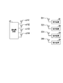
- FIG. 1 is a schematic diagram showing an example of a communication system according to the first embodiment of the present invention.
- the communication system includes a base station apparatus a1 and a plurality of terminal apparatuses B1 to BN.
- the base station apparatus a1 includes K transmission antennas a161 to a16K.
- the present invention is not limited to this, and K ⁇ 4 or K> 4.
- the base station apparatus a1 spatially multiplexes and transmits signals addressed to the four terminal apparatuses B1 to B4 using the same frequency at the same time.
- the terminal apparatuses B1 to BN have different distances from the base station apparatus a1, the reception qualities of the signals transmitted from the base station apparatus a1 are different.
- interference occurs between signals to terminal apparatuses B1 to BN.
- the base station apparatus a1 preliminarily transmits a signal addressed to a certain terminal apparatus so as to eliminate interference caused by signals addressed to other terminal apparatuses.
- the base station apparatus a1 selects one of a plurality of precodings and uses the precoding.
- precoding means that a signal to be originally transmitted is subjected to some processing to convert a plurality of transmission signals into signals that can be spatially multiplexed.
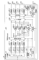
- FIG. 2 is a schematic block diagram showing the configuration of the base station apparatus a1 according to this embodiment.
- a base station apparatus a1 includes a receiving antenna a111, a radio unit a112, an upper layer unit a12, encoding units a131-1 to a131-N, modulation units a132-1 to a132-N, a multiplexed signal generation unit a14, A second reference signal generation unit a151, a first reference signal generation unit a152, a filter multiplication unit a153, a signal multiplexing unit a154, radio units a155-1 to a155-K, and transmission antennas a161 to a16K are configured.
- the upper layer unit a12 includes an application unit a121, a reception quality acquisition unit a122, and a precoding determination unit a123.
- the multiplex signal generation unit a14 includes an operation order selection unit a141, a filter calculation unit a142, an interference calculation unit a143, subtraction units a144-2 to a144-N, modulo operation units a145-2 to a145-N, and a filter multiplication unit a146. Consists of.
- the base station apparatus a1 receives signals transmitted from the terminal apparatuses B1 to BN using the reception antenna a111.
- a signal received by the receiving antenna a111 is input to the wireless unit a112.
- the radio unit a112 generates a baseband signal by down-converting the input signal and performs A / D (Analog to Digital) conversion.
- the radio unit a112 demodulates the A / D converted signal, and outputs the demodulated information to the upper layer unit a12.
- the radio unit a112 outputs the reception quality information (CQI; Channel Quality Information) of each terminal apparatus Bn to the reception quality acquisition unit a122, and the propagation path information (CSI; Channel State Information).
- CQI Channel Quality Information
- the reception quality information of each terminal device Bn is information indicating the reception quality at each terminal device of the signal from the base station device a1, and for example, the distance from the base station device a1 to each terminal device Bn and the base station It depends on the presence or absence of obstacles between terminals, whether the terminal is located indoors or outdoors, and the like. Specifically, when the reception quality information represents reception SNR (Signal-to-Noise Ratio) in each terminal apparatus Bn, the terminal apparatus Bn located in the vicinity of the base station apparatus a1 Since the signal is received with a high SNR, the reception quality indicated by the reception quality information also has a high value. On the contrary, in the terminal device Bn located at a location away from the base station device a1, the reception quality indicated by the reception quality information is a low value.
- SNR Signal-to-Noise Ratio
- the base station apparatus a1 determines the coding rate and the modulation scheme of information addressed to each terminal apparatus Bn (also addressed to the receiving antenna Bn1) based on the reception quality information and propagation path information in each terminal apparatus Bn. decide. In addition, the base station apparatus a1 transmits the determined coding rate of information addressed to each terminal apparatus Bn and control information indicating a modulation scheme to each terminal apparatus Bn.
- Information addressed to each terminal device Bn is input to the application unit a121 of the upper layer unit a12, for example, via a network.
- the application unit a121 outputs each piece of information addressed to the terminal devices B1 to BN to the encoding units a131-1 to a131-N, respectively.
- the reception quality acquisition unit a122 outputs the reception quality information input from the radio unit a112 to the precoding determination unit a123, the calculation order selection unit a141, and the filter calculation unit a142.
- the precoding determination unit a123 determines one precoding from a plurality of precodings based on the reception quality information input from the reception quality acquisition unit a122. Specifically, the precoding determination unit a123 determines whether the difference in reception quality between the terminal devices Bn (that is, the terminal devices B1 to B4) that multiplex the signals is smaller than a predetermined threshold (for example, the reception SNR is 3 dB). Determine whether or not. If the precoding determination unit a123 determines that the difference in reception quality is smaller than the threshold, the precoding determination unit a123 determines precoding as ZF-THP.
- the precoding determination unit a123 determines the precoding to be ZF-THP when there is no significant difference in the reception quality between the terminal apparatuses Bn and the reception quality is comparable. On the other hand, if the precoding determination unit a123 determines that the difference in reception quality is greater than or equal to the threshold, the precoding determination unit a123 determines precoding to be QR-THP. That is, precoding determining section a123 determines precoding to be QR-THP when there is a large difference in reception quality between terminal apparatuses Bn and reception quality is biased. The precoding determination unit a123 outputs precoding information indicating the determined precoding to the filter calculation unit a142.
- the encoding unit a131-n encodes the information addressed to the terminal device Bn input from the application unit a121 at the encoding rate determined by the base station device a1 and the encoding rate of the information addressed to the terminal device Bn. .
- Encoding section a131-n respectively, and outputs the information d n which is encoded in the modulation unit a132-n.
- Modulation unit a132-n are information d n input from the encoding unit a131-n, the base station apparatus a1 is modulated by the modulation scheme determined information addressed to the mobile station Bn. Examples of the modulation method include QPSK (Quadrature Phase Shift Keying) and 16QAM (Quadrature Amplitude Modulation).
- Modulation unit a132-n the signal S n of the modulated output to the calculation order selection unit a141 of the multiplex signal generating unit a14.
- the calculation order selection unit a141 may receive precoding information from the precoding determination unit a123. Only when the input precoding information indicates QR-THP, the calculation order selection unit a141 selects the output destination based on the reception quality information. You may choose.
- the filter calculation unit a142 generates a propagation matrix H from the propagation path information input from the wireless unit a112.
- the filter calculation unit a142 arranges the elements H mk in the order of m based on the reception quality information input from the reception quality acquisition unit a122.
- Filter calculating section a142 is a complex conjugate transpose of the generated propagation matrix H (the Hermitian conjugate) matrix H H to QR decomposition to calculate the matrix R and matrix Q.
- QR decomposition is to decompose a matrix into a unitary matrix Q and an upper triangular matrix R.
- the filter calculation unit a142 outputs information indicating the calculated matrix R to the interference calculation unit a143.
- the filter calculation unit a142 outputs the calculated matrix Q as a filter coefficient to the filter multiplication unit a146 and the filter multiplication unit a153.
- the filter calculation unit a142 uses a matrix obtained by multiplying the calculated matrix Q by ⁇ diag (R H ) ⁇ ⁇ 1 as a filter coefficient.
- diag (X) represents a matrix in which the non-diagonal component of the matrix X is zero.
- Subtraction unit a 144-m are input signals s m from calculation order selection unit a141, is input to the interference signal f m from the interference calculation section a143. Subtraction unit a 144-m subtracts the interference signal f m from the signal s m. The subtraction unit a144-m outputs the subtracted signal s m -f m to the modulo operation unit a145-m. The modulo operation unit a145-m performs a modulo operation (nonlinear operation) on the signal s m -f m input from the subtraction unit a144-m, based on the modulation scheme of each terminal device Bm determined by the base station device a1. Do. The modulo calculator a145-m outputs the signal s m ′ after the modulo calculation to the interference calculator a143 and the filter multiplier a146.
- the filter multiplier a146 multiplies the generated vector s N ′ by the filter coefficient indicated by the information input from the filter calculator a142.
- the filter multiplication unit a146 outputs the signal of the vector component after multiplication to the signal multiplexing unit a154.
- the second reference signal generation unit a151 generates a pilot signal (reference signal) to be transmitted from each of the transmission antennas a16k.
- the pilot signal is a signal that is known between the base station apparatus a1 and the terminal apparatus b1 (a waveform thereof is stored in advance), and the transmission antennas a161 to 161 are used so that pilot signals transmitted from a plurality of transmission antennas do not interfere with each other.
- a164 is orthogonalized. Note that the pilot signal generated by the second reference signal generation unit a151 is used in each terminal apparatus b1 to estimate the propagation path information to be notified to the base station apparatus a1.
- the second reference signal generation unit a151 outputs the generated pilot signal to the signal multiplexing unit a154.
- the first reference signal generation unit a152 generates a pilot signal.
- the pilot signal is a signal that is known between the base station apparatus a1 and the terminal apparatus b1 (a waveform thereof is stored in advance), and the transmission antennas a161 to 161 are used so that pilot signals transmitted from a plurality of transmission antennas do not interfere with each other. a164 is orthogonalized. Note that the pilot signal generated by the first reference signal generation unit a152 is used in each terminal apparatus b1 to demodulate a desired signal among spatially multiplexed signals. The first reference signal generation unit a152 outputs the generated pilot signal to the filter multiplication unit a153.
- the filter multiplier a153 multiplies the filter coefficient indicated by the information input from the filter calculator a142 by the pilot signal input from the first reference signal generator a152.
- the filter multiplier a153 outputs the multiplied signal to the signal multiplexer a154.
- the signal multiplexer a154 multiplexes signals input from the filter multiplier a146, the second reference signal generator a151, and the filter multiplier a153.
- the pilot signal input from the second reference signal generation unit a151 and the signal input from the filter multiplication unit a153 are orthogonalized and multiplexed in the time domain, for example.
- the signal multiplexing unit a154 arranges the signal of the remainder calculation information indicating that the modulo calculation is performed in the band assigned to the terminal device Bm (m ⁇ 2) in the control information signal. After performing such signal multiplexing, the signal multiplexing unit a154 outputs the signal transmitted by the transmission antenna a16k to the radio unit a155-k.
- the radio unit a155-k performs D / A (Digital to Analog) conversion on the signal input from the signal multiplexing unit a154.
- the radio unit a155-k upconverts the converted signal to a radio frequency and transmits the signal to the terminal device Bn via the transmission antenna a16k.
- the filter calculation unit a142 generates a propagation matrix H of the following equation (1).
- the filter calculation unit a142 calculates a filter coefficient Q for triangulating the propagation path matrix H. Specifically, filter calculating section a142, as shown in the following equation (2), the complex conjugate transpose matrix H H of the propagation matrix H to QR decomposition to calculate the matrix R and the filter coefficient (matrix Q).
- the subtracted signal s m ⁇ f m output from the subtraction unit a144-m is expressed by the following equation (3).
- the modulo calculation unit a145-m performs a modulo calculation represented by the following equation (4).
- Re [u] and Im [u] represent the real part and the imaginary part of the complex number u, respectively.
- the floor function calculation represents the smallest integer greater than or equal to w.
- the second item and the third item of Equation (4) indicate that the real part and imaginary part of u are integer multiples of ⁇ .
- the base station apparatus a1 can limit the amplitude of the transmission signal so that the amplitude of the signal after interference subtraction is within a predetermined width, and can suppress an increase in transmission power.
- the signal output from the modulo arithmetic unit a145-m for example, the signal s 2 'is expressed by the following equation (5).
- Equation (6) represents an equivalent propagation path including the filter coefficient between the base station apparatus a1 and the terminal apparatus b1.
- the filter coefficient calculation processing of the filter calculation unit a142 may not be QR decomposition. That is, the filter calculation unit a142 may calculate a matrix that becomes a triangular matrix when multiplied by the propagation path matrix H as a filter coefficient.
- R 44 ⁇ R 33 ⁇ R 22 ⁇ R 11 because of the nature of QR decomposition.
- calculation order selection unit a141 the reception quality is rearranged signal S n to the low order.
- the base station apparatus a1 is to increase the amplitude of the signal s m value is smaller reception quality is lower terminals addressed Bm of m, of the signal s m value greater reception quality is higher terminal addressed Bm of m
- the amplitude can be reduced.
- equation (7) is the received signal y m, indicating that the interference from the signal addressed to another terminal device is removed.
- the reception signal vector y is expressed by the following equation (8).
- the base station apparatus a1 is the amplitude of the signal s m addressed to the mobile station Bm can be the same order of magnitude.
- the base station apparatus a1 when the base station apparatus a1 spatially multiplexes signals destined for a plurality of terminals having the same distance from the base station, the base station apparatus a1 uses ZF-THP to the by using QR-THP in the case of spatial multiplexing, irrespective of the difference of the reception quality of the terminal device Bm, the amplitude of the signal y m that terminal Bm receives can be of the same order of magnitude The reception quality can be kept at the same level in all the terminal devices. That is, the base station apparatus a1 can flexibly control reception quality in a plurality of terminal apparatuses.
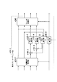
- FIG. 3 is a schematic block diagram illustrating the configuration of the terminal device b1 according to the present embodiment.
- the terminal device b1 includes a reception antenna b111 (Bn1), a radio unit b112, a signal separation unit b113, a control signal processing unit b114, a propagation path estimation unit b115, a propagation path compensation unit b116, a remainder determination unit b117, a modulo calculation.
- the radio unit b112 receives a signal via the receiving antenna b111 (a signal received by the terminal device Bm is a received signal y m ). This signal includes a pilot signal, an information signal addressed to the terminal device Bm, and a control information signal. The radio unit b112 down-converts the received signal to generate a baseband signal, and performs A / D (Analog to Digital) conversion. The radio unit b112 outputs the converted signal to the signal separation unit b113.
- the signal separation unit b113 separates the signal input from the radio unit b112, outputs a control information signal to the control information reception unit b113, and outputs a pilot signal to the propagation path estimation unit b115.
- the signal separation unit b113 outputs a signal of information addressed to the own device among the separated signals to the propagation path compensation unit b116.
- the control signal processor b114 demodulates and decodes the control information signal input from the signal separator b113.
- the control signal processing unit b114 outputs the remainder calculation information and the modulation scheme among the decoded control information to the residue determination unit b117 and the modulo calculation unit b118, respectively.
- Control signal processing section b114 outputs coding rate and modulation scheme information among the decoded control information to demodulation section b119 and decoding section b120, respectively (not shown).
- the propagation path estimation unit b115 estimates a propagation path estimation value for each antenna based on the pilot signal generated by the second reference signal generation unit a151 among the pilot signals input from the signal separation unit b113. Moreover, the propagation path estimation part b115 measures reception quality using this pilot signal. Note that this measurement may be performed using a pilot signal transmitted in a frame different from the data signal.
- the propagation path estimation part b115 outputs the propagation path information which shows the estimated propagation path estimated value, and the reception quality information which shows the measured reception quality to the upper layer part b121.
- the propagation path estimation unit b115 based on the pilot signal generated by the first reference signal generation unit a152, among the pilot signals input from the signal separation unit b113, the equivalent propagation path (base The propagation path estimation value of the propagation path including the filter coefficient multiplied by the station apparatus a1 is estimated.
- the propagation path estimation unit b115 outputs equivalent propagation path estimation information indicating the estimated propagation path estimated value of the equivalent propagation path to the propagation path compensation unit b116.
- the propagation path compensation unit b116 performs propagation path compensation by dividing the signal according to the propagation path estimation value indicated by the equivalent propagation path estimation information input from the propagation path estimation unit b115.
- the propagation path compensation unit b116 outputs the signal subjected to propagation path compensation to the remainder determination unit b117.
- the residue determination unit b117 When the remainder calculation information is input from the control signal processing unit b114, the residue determination unit b117 outputs the signal input from the propagation path compensation unit b116 to the modulo calculation unit b118. On the other hand, when the remainder calculation information is not input from the control signal processing unit b114, the residue determination unit b117 outputs the signal input from the propagation path compensation unit b116 to the demodulation unit b119. With this configuration, the remainder determination unit b117 of the terminal device B1 outputs the input signal to the demodulation unit b119, and the residue determination unit b117 of the terminal devices B2, B3, and B4 outputs the input signal to the modulo operation unit b118. It will be.
- the modulo operation unit b118 performs the same modulo operation as that of the base station device a1 (modulo operation represented by Expression (4)).
- the modulo calculation unit b118 selects ⁇ corresponding to the modulation scheme indicated by the information input from the control signal processing unit b114, and performs the modulo calculation using the ⁇ .
- the modulo calculation unit b118 outputs the calculated signal to the demodulation unit b119.
- the demodulation unit b119 demodulates the signal input from the remainder determination unit b117 or the modulo calculation unit b118 using the modulation scheme indicated by the information input from the control signal processing unit b114.
- the demodulator b119 outputs information obtained by demodulating the signal to the decoder b120.
- the decoding unit b120 decodes the information input from the demodulation unit b119 based on the coding rate indicated by the information input from the control signal processing unit b114.
- the demodulation unit b119 outputs the decoded information to the upper layer unit b121.
- the upper layer part b121 outputs the information input from the decoding part b120 to an output part (not shown), or controls the terminal device b1 based on the information.
- the upper layer unit b121 outputs the reception quality information and the channel information input from the channel estimation unit b115 to the radio unit b122 as signals addressed to the base station apparatus a1.
- the radio unit b122 modulates the information input from the higher layer unit b121, and D / A converts the modulated signal.
- the radio unit b122 up-converts the converted signal to a radio frequency and transmits it to the base station apparatus a1 via the transmission antenna b123.
- the base station apparatus a1 selects precoding for spatially multiplexing signals addressed to a plurality of terminal apparatuses Bm from a plurality of precoding (ZF-THP, QR-THP), Send the selected precoded signal.
- the communication system can select precoding from a plurality of precodings that have different reception qualities, and can flexibly control the reception quality in the plurality of terminal apparatuses Bm.
- ZF-THP is obtained by multiplying each signal addressed to a plurality of terminal apparatuses Bm by the same value “1” (or not multiplied by a value) (see Expression (8)).
- the base station apparatus a1 selects ZF-THP when the difference in reception quality addressed to the plurality of terminal apparatuses Bm is smaller than a predetermined value.
- the terminal device Bm can receive a signal so that reception quality may become the same as it is, when the reception quality in several terminal device Bm is comparable.
- QR-THP is obtained by multiplying signals addressed to a plurality of terminal apparatuses Bm by different values (see Expression (3)).
- the base station apparatus a1 selects QR-THP when the difference in reception quality for a plurality of terminal apparatuses Bm is larger than a predetermined value. Thereby, the terminal device Bm can receive a signal so that the reception quality in each terminal device Bm becomes comparable, when there is a big difference in the reception quality in several terminal device Bm.
- the base station apparatus a1 may select precoding based on the reception quality information and the data amount of information addressed to each terminal apparatus. For example, even when the base station apparatus a1 determines that the difference in reception quality is smaller than the threshold value, if the difference in data amount of information addressed to each terminal apparatus is equal to or greater than a predetermined threshold value, the base station apparatus a1 selects QR-THP. May be. In this case, the base station apparatus a1 (calculation order selection unit a141), the signal S n of more terminal devices destined Bn amount of data in the m-th signal s m.
- the base station apparatus a1 can reliably transmit a signal by increasing the reception quality of the signal addressed to the terminal apparatus Bm having a large amount of data.
- the base station apparatus a1 can prevent retransmission from occurring frequently due to an error occurring in the larger data amount, thereby preventing deterioration in transmission efficiency and increase in processing load.
- information addressed to a terminal device having a large amount of data is modulated by a modulation method having a high modulation multi-level number (for example, 16QAM), and information addressed to a terminal device having a small data amount is modulated by a modulation method having a small number of modulation multi-values. You may modulate by (for example, QPSK).
- base station apparatus a1 demonstrated the case where precoding was performed using QR decomposition
- the present invention is not limited to this, and precoding that generates filter coefficients based on the inverse matrix of the propagation path matrix may be used, and the mean square error between the transmission signal and the reception signal in each terminal device is minimized. In this way, precoding that calculates filter coefficients according to the MMSE norm may be used.
- FIG. 4 is a schematic diagram illustrating an example of a communication system according to the second embodiment of the present invention.
- the communication system includes a base station device a2 and a plurality of terminal devices B1 to BN.
- the base station apparatus a2 includes four transmission antennas a161 to a164.
- the base station device a2 spatially multiplexes and transmits signals addressed to the two terminal devices B1 and B2 using the same frequency at the same time.
- the terminal apparatuses B1 to BN have different distances from the base station apparatus a2, the reception qualities of the signals transmitted from the base station apparatus a2 are different.
- interference occurs between signals to terminal apparatuses B1 to BN.
- the base station apparatus a2 performs precoding on a signal addressed to a certain terminal apparatus in advance so as to remove interference caused by a signal addressed to another terminal apparatus.
- the base station apparatus a2 selects one of a plurality of precodings and uses the precoding.
- this embodiment demonstrates the case where terminal device Bn is provided with the same number (two) receiving antenna, this invention is not limited to this, The receiving antenna number of terminal device Bn may differ.
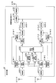
- FIG. 5 is a schematic block diagram illustrating a configuration of the base station device a2 according to the present embodiment.
- the base station apparatus a2 (FIG. 5) according to the present embodiment is compared with the base station apparatus a1 (FIG. 2) according to the first embodiment, the precoding determining section a223 of the higher layer section a22 and the multiple signal generating section a24 is different.
- the multiplexed signal generation unit a24 includes a precoding selection unit a240, a first precoding unit a24-1, and a second precoding unit a24-2.
- the precoding determination unit a223 determines precoding to be BD (Block Diagnostics). That is, the precoding determination unit a223 determines the precoding to be BD when there is no large difference in reception quality between the terminal apparatuses Bn and the reception quality is comparable. On the other hand, if the precoding determination unit a223 determines that the difference in reception quality is equal to or greater than the threshold, the precoding determination unit a223 determines precoding to be BT (Block Trigulation) -THP.
- BD Block Diagnostics
- the precoding determination unit a223 determines the precoding to be BT-THP when there is a large difference in reception quality between the terminal apparatuses Bn (for example, reception SNR is 5 dB) and reception quality is biased. It becomes.
- the precoding determination unit a223 outputs precoding information indicating the determined precoding to the precoding selection unit a240.
- the precoding determination unit a223 encodes and modulates the precoding information and outputs the encoded information to the signal multiplexing unit a154.
- the output precoding information signal is multiplexed by the signal multiplexing unit a154 and transmitted to each terminal apparatus b2.
- the second term indicates that a sum is taken of the total number J s of receiving antennas of the terminal device Bs (s is n ⁇ 1 or less).
- Precoding selection unit a240 when precoding information input from precoding determining section a223 indicates BD, the signal S i and inputted, outputs the reception quality information to the first precoding part a24-1 To do.
- precoding selection unit a240 when precoding information input from precoding determining section a223 indicates BT-THP is a signal S i and the reception quality information inputted second precoding part a24- Output to 2.
- FIG. 6 is a schematic block diagram showing the configuration of the first precoding unit a24-1 according to the present embodiment.
- the first precoding unit a24-1 includes a filter calculation unit a24-12 and a filter multiplication unit a246.
- the filter calculation unit a24-12 generates a propagation matrix H from the propagation path information input from the radio unit a112.
- the filter calculation unit a24-12 calculates a matrix M in which the matrix is block diagonalized.
- block diagonalization refers to a component (referred to as a non-diagonal block) other than a diagonal component (referred to as a diagonal block) in a block when the matrix component is an element (referred to as a block) for each terminal device b2. Is 0 (see equation (13)).
- the filter calculation unit a24-12 outputs the calculated matrix M as a filter coefficient to the filter multiplication unit a246 and the filter multiplication unit a153.
- the filter multiplier a246 multiplies the generated vector s i 'by the filter coefficient indicated by the information input from the filter calculator a142.
- the filter multiplication unit a246 outputs the vector component signal after multiplication to the signal multiplexing unit a154.
- the signal multiplexing unit a154 arranges the signal generated from the signal s i ′ and output in the band transmitted by the transmission antenna a16i.
- FIG. 7 is a schematic block diagram showing the configuration of the second precoding unit a24-2 according to the present embodiment.
- the functions of the subtracting units a144-3 to a144-4 and the modulo calculating units a145-3 to a145-4 are the same as those of the first embodiment, and thus description thereof is omitted.
- the function of the filter multiplication unit a246 is the same as that of the first precoding unit (FIG. 6), but the description thereof is omitted.
- Calculation order selection unit a141 outputs the signal s 1, s 2 to the filter multiplication unit a246 and the interference calculation section A24-23, and outputs the signal s i to (i ⁇ 3), each subtraction unit a 144-i.
- the filter calculation unit a24-22 generates a propagation matrix H from the propagation path information input from the radio unit a112. When the generated propagation matrix H is multiplied, the filter calculation unit a24-22 calculates a matrix M in which the matrix is triangulated downward.
- block triangulation means that one matrix of non-diagonal components (referred to as non-diagonal blocks) in a block is 0 when the matrix component is an element (block) for each terminal device b2. (See equation (23)).
- the filter calculation unit a24-22 outputs the calculated matrix M as a filter coefficient to the filter multiplication unit a246 and the filter multiplication unit a153.
- the filter calculation unit a24-22 outputs information indicating the matrix A as a result of multiplying the propagation matrix H by the matrix M to the interference calculation unit a24-23.
- Diag (X) represents a matrix in which the non-diagonal block of the matrix X is zero.
- the interference calculation unit a24-23 sequentially generates a vector s i ′ having the signal s i input from the precoding selection unit a240 as a component.
- the interference calculation unit a24-23 multiplies the interference coefficient matrix C by the vector s i ′ to generate the interference signal f i . That is, the interference calculation section a142 the interference signal f 3 is the third component of the interference coefficient matrix C (s 1, s 2, 0,0) obtained by multiplying the T matrix, the interference signals f 4, the interference coefficient matrix A fourth component of a matrix obtained by multiplying C by (s 1 , s 2 , 0, 0) T is generated.
- the interference coefficient matrix C s 1, s 2, 0,0
- the interference calculation unit a24-23 generates only the vector s I ′ having the signal s i as a component. However, when there are N or more terminal devices, the modulo calculation unit a145. Signals s J1 + 1 to s I-JN may be input from ⁇ (J 1 +1) to a145- (I ⁇ J N ).
- J1 is the number of reception antennas of the terminal device B1
- JN is the number of reception antennas of the terminal device BN.
- the interference calculating unit a24-23 sequentially generates a vector s I ′ including the signal s i and the signals s J1 + 1 to s I-JN as components.
- Interference calculator a24-23 the generated interference signal f i, respectively, and outputs to the subtraction section a 144-i.
- the filter calculation units a24-12 and a24-22 generate the propagation matrix H of Expression (1).
- Filter calculating section a24-12, a24-22 is the propagation matrix H is extracted for each terminal device n (referred propagation matrix H n).
- the filter calculation units a24-12 and a24-22 extract the following expressions (9) and (10).
- filter calculating section a24-12 the singular value decomposition of the propagation matrix H n (SVD: Singular Value Decomposition ) is. Specifically, the filter calculation unit a24-12 calculates the respective matrices U n ′, D n ′, and V n ′ H expressed by the following equation (11).
- the matrix U n ′ is a unitary matrix with J n rows and J n columns
- the matrix D n ′ is J n rows and K columns, with the exception of the diagonal components being 0, and the diagonal components being non-negative.
- the matrix V n ′ H is a unitary matrix with K rows and K columns. Decomposing a matrix in this way is called singular value decomposition. By using this matrix V n ′ H , the signal addressed to the terminal device Bn can be prevented from reaching other terminal devices in the communication system.
- the filter calculation unit a24-12 extracts a 4 ⁇ 2 matrix (V n, 2 ) that is the right half (3, 4 columns) of the matrix V n ′ H.
- the filter calculation unit a24-12 uses the matrix V n, 2 to calculate the matrix M ′ of the following equation (12).
- the base station apparatus transmits the transmission signal by performing precoding of Expression (12) and passes through the propagation path, the propagation equivalent to the propagation path obtained by multiplying the matrix M ′ by the propagation path matrix H when viewed from the terminal apparatus side. It becomes a road and becomes the following formula (13).
- Equation (13) indicates that when a signal multiplied by the matrix M is received via a propagation path, no interference is received from signals addressed to other terminal apparatuses. That is, the propagation path indicated by Equation (13) is two SU-MIMO (Single User-MIMO) propagation paths.
- the filter calculation unit a24-12 performs singular value decomposition of H 1,1 and H 2,2 as shown in the following equations (16) and (17), respectively.
- the matrix U n, n is a 2 ⁇ 2 unitary matrix
- the matrix D n is 2 ⁇ 2 and is 0 except for the diagonal component
- the diagonal component is a non-negative matrix
- the matrix V n is a 2 ⁇ 2 unitary matrix. It is.
- the filter calculation unit a24-12 calculates the matrix M by the following equation (18).
- the filter multiplier a246 multiplies the signal by using the matrix M of Expression (18) as a filter coefficient.
- filter calculating section a24-22 as in the equation (19), singular value decomposition propagation matrix H 1.
- Expression (18) is used as the filter coefficient
- the present invention is not limited to this, and the filter coefficient calculated by the filter calculation unit a24-12 is multiplied by the propagation path matrix H. In such a case, any filter coefficient may be used as long as the matrix after multiplication is block diagonalized.
- the matrix V 1 is a 4 ⁇ 4 unitary matrix.
- Filter calculating section a24-22 the matrix V 1 was a 4 2 matrix is the left half of the matrix V 1 (1, 2 columns), the matrix of 4 rows and two columns is the left half (3, 4 columns) Are extracted as matrix V 1,1 and matrix V 1,2 respectively.
- the filter calculation unit a24-22 calculates the matrix V 2 ′ by performing singular value decomposition on the matrix obtained by multiplying the matrices V 1 and 2 by the matrix H 2 . Specifically, the filter calculation unit a24-22 calculates V 2 ′ that satisfies the following expressions (20) and (21).
- the filter calculation unit a24-22 calculates the matrix M by the following equation (22).
- the filter multiplier a246 multiplies the signal by using the matrix M in Expression (22) as a filter coefficient.
- a signal transmitted by performing precoding of Expression (22) on the transmission signal and received via the propagation path is multiplied by the propagation path matrix H to the matrix M of Expression (22) on the terminal apparatus side. It is the same as that via a propagation path equivalent to the generated propagation path. This equivalent propagation path is expressed by the following equation (23).
- Equation (23) represents an equivalent propagation path including the filter coefficient between the base station device a2 and the terminal device b2. Equation (23) indicates that the block is triangulated.
- Expression (23) is used as the filter coefficient has been described.
- the present invention is not limited to this, and the filter coefficient calculated by the filter calculation unit a24-22 is multiplied by the propagation path matrix H.
- the filter coefficient may be any filter coefficient that performs block triangulation on the matrix after multiplication.
- the off-diagonal component of Expression (23) indicates that the signal addressed to the terminal device B1 reaches the terminal device B2 and becomes an interference signal.
- the interference calculation unit a24-23 calculates this interference signal. Specifically, the interference calculation unit a24-23 calculates the interference signals f 3 and f 4 using the following equation (24).
- the modulo calculators a145-3 to a145-4 subtract the interference signals f 3 and f 4 calculated by the interference calculator a24-23 from the signals s 3 and s 4 , respectively.
- the vector s i is multiplied by a block diagonalized matrix. That is, spatial multiplexing can be realized so that signals addressed to a plurality of terminal devices do not interfere with each other.
- FIG. 8 is a schematic block diagram showing the configuration of the terminal device b2 according to the present embodiment.
- the terminal device b2 includes receiving antennas b111-1 (Bn1), b111-2 (Bn2), radio units b112-1, b112-2, signal separating units b213-1, b213-2, and a control signal processing unit.
- reception antennas b111-1 and b111-2 are the same as those of the reception antenna b111
- the functions of the radio units b112-1 and b112-2 are the same as those of the radio unit b112
- the signal separation unit b213-1 , B213-2 has the same function as the signal separator b113.
- the functions of the control signal processing units b114-1 and b114-2 are the same as those of the control signal processing unit b114
- the functions of the residue determination units b117-1 and b117-2 are the same as those of the residue determination unit b117.
- the functions of the modulo operation units b118-1 and b118-2 are the same as those of the modulo operation unit b118, the functions of the demodulation units b119-1 and b119-2 are the same as those of the demodulation unit b119, and the decoding units b120-1, The function of b120-2 is the same as that of the decoding unit b120.
- the functions of the propagation path estimation unit b115, the upper layer unit b121, and the radio unit b122 are the same as those in the first embodiment. Description of these functions is omitted.
- the coefficient estimation unit b224 receives precoding information signals and pilot signals from the signal separation units b213-1 and b213-2.
- the coefficient estimation unit b224 demodulates and decodes the precoding information signal.
- the coefficient estimation unit b224 calculates the filter coefficient of Expression (18) and outputs it to the MIMO demultiplexing unit b216.
- the coefficient estimation unit b224 calculates the filter coefficient of Expression (22) and outputs it to the MIMO demultiplexing unit b216.
- precoding information is output to the coefficient demultiplexing unit b224 to the MIMO demultiplexing unit b216.
- MIMO demultiplexing section b216 of the terminal device Bn based on the channel information input from the channel estimation unit B115, generates a propagation matrix H n.
- MIMO demultiplexing section b216 based on the generated filter coefficient input from the propagation matrix H n and a coefficient estimation section b224 has, to extract a signal.
- the MIMO demultiplexing unit b216 calculates the matrices U n, n of Expressions (16) and (17).
- the MIMO demultiplexing unit b216 performs the matrix U 1 in the equation (19) (in the case of the terminal device B1) or the equation (21).
- Matrix U 2 ′ (in the case of the terminal device B2) is calculated.
- the base station apparatus b2 transmits in advance information indicating whether each terminal apparatus is the terminal apparatus B1 or B2 to each terminal apparatus, and the MIMO demultiplexing unit b216 determines based on this information.
- the matrix U 1 or U 2 ′ may be calculated.
- the MIMO demultiplexing unit b216 multiplies the signals input from the signal demultiplexing units b213-1 and b213-2 by the calculated matrix U n, n , matrix U 1 or matrix U 2 ′.
- a matrix obtained by multiplying the product HM of the matrix of Expression (24) by U 2 ′ is D 2 ′ (diagonal matrix), so MIMO demultiplexing unit b216 extracts a signal by dividing the D 2 '.
- the MIMO demultiplexing unit b216 extracts the signal of each stream.
- the MIMO demultiplexing unit b216 outputs the extracted signal to the residue determination units b117-1 and b117-2 for each of the reception antennas b111-1 and b111-2.
- the base station apparatus a1 selects and selects precoding for spatially multiplexing signals addressed to a plurality of terminal apparatuses Bn from a plurality of precodings (BD, BT-THP). Send the precoded signal.
- the communication system can select precoding from a plurality of precodings that have different reception qualities, and can flexibly control the reception quality in the plurality of terminal apparatuses Bn.
- the MU-MIMO system includes a plurality of precoding means, and by selecting and using the precoding means, MU-MIMO transmission utilizing the characteristics of various precoding means can be performed. This can be realized and transmission characteristics can be improved.
- precoding means according to the combination of terminals to be subjected to spatial multiplexing it is possible to select an appropriate precoding means according to the situation.
- the MIMO demultiplexing unit b216 calculates the matrix U n, n , the matrix U 1, or the matrix U 2 ′ has been described, but the present invention is not limited to this.
- the base station apparatus a2 may calculate these matrices and transmit the calculated matrix information to the terminal apparatus b2.
- the MIMO demultiplexing unit b216 of the terminal device b2 extracts a signal using the received matrix information.
- the MIMO demultiplexing unit b216 may extract the signal by other processing. For example, two received signals in other terminal devices may be separated by MMSE (Minimum Mean Square Error) or MLD (Maximum Likelihood Detection).
- MMSE Minimum Mean Square Error
- MLD Maximum Likelihood Detection
- the remainder determination units b117-1 and b117-2 select an output destination according to the remainder calculation information, but indicate precoding information and the terminal device B1 or B2.
- the output destination may be selected according to the information. For example, when the precoding information is BT-THP and the terminal device B2, the remainder determination units b117-1 and b117-2 output to the modulo arithmetic units b118-1 and b118-2, respectively. In other cases, the data is output to the demodulation units b119-1 and b119-2.
- the processing of the filter calculation unit in the case of two terminal devices has been described.
- the present invention is not limited to this, and two or more terminal devices may be used.
- an example of processing of the filter calculation unit in this case will be described.
- the filter calculation unit a24-12 performs the following processing. If a channel matrix other than the n-th terminal device Bn is H n ⁇ (tilde), it can be expressed by the following equation.
- the left singular vector U n ⁇ represents the unitary matrix on the terminal device side
- D n ⁇ represents the diagonal matrix (singular value)
- the right singular vectors V n ⁇ H represent the unitary matrix on the base station device side.
- V n to H are matrices of K rows and K columns.
- V n ⁇ (hat)
- V n ⁇ is V n ⁇ H
- the right side J n (the number of receiving antennas of the n-th terminal device) is a matrix extracted. Therefore, when the filter coefficient for block diagonalization in BD is M ′, it can be expressed as the following equation (28).
- the transmission signal is transmitted by performing precoding of Expression (28), and when passing through the propagation path, when viewed from the terminal apparatus side, the propagation path matrix H multiplied by the matrix M ′ It becomes an equivalent propagation path.
- the SU-MIMO propagation path in each terminal device is set as HM n ′, and each is subjected to singular value decomposition as shown in the following equation.
- the filter calculation unit a24-12 calculates the filter coefficient M by the following equation (30).
- the filter calculation unit a24-22 performs the following processing.
- the filter coefficient for block triangulation in BT-THP is M ′, it can be expressed as the following equation (31).
- V n ′ is calculated as in the following equation (32).
- n is N, N-1, ..., and calculates the respective V n 'to 2 order.
- a propagation path matrix extracted for block triangulation of H n is defined as B n T
- the remaining propagation path matrix is defined as B n ⁇ (tilde) T.
- V n ′ of Equation (31) is obtained by performing singular value decomposition on B n .
- the transmission signal is transmitted by performing precoding of Expression (31), and when passing through the propagation path, the propagation path matrix H is multiplied by the matrix M ′ from the right when viewed from the terminal apparatus Bn side.
- the propagation path is equivalent to the propagation path.
- HM ′ becomes a channel triangulation channel matrix.
- a channel matrix composed of each transmission antenna and each terminal device Bn is extracted.
- This extracted propagation path matrix is a single user MIMO propagation path matrix of the base station apparatus a2 and each terminal apparatus Bn arranged in a diagonal component.
- A11, A12, A21, A22 , A33, A34, A43, and A44 other than the components are replaced with zero. If this matrix is A and the SU-MIMO propagation path in each terminal apparatus Bn is A n ′, the following equation (33) is obtained.
- the filter calculation unit a24-22 calculates the filter coefficient M by the following equation (35).
- the base station devices a1 and a2 may receive the reception quality information in units of frames from the terminal device Bn.
- the base station apparatus a1 may select precoding for each frame, or may be performed at shorter or longer time intervals.
- the base station devices a1 and a2 store a combination of identification information of the terminal device Bn and information indicating precoding selected in advance based on the reception quality information. The base station devices a1 and a2 select precoding based on the stored information.
- base station apparatuses a1 and a2 select precoding based on reception quality information, and store a combination of identification information of terminal apparatus Bn and information indicating the selected precoding. Repeat that. Further, the period for which precoding is used for selection may not be a predetermined period. For example, the period may be determined according to the moving speed of the terminal apparatus Bn. Specifically, the period may be shorter as the moving speed of the terminal apparatus Bn is larger, and the period may be longer as the moving speed of the terminal apparatus Bn is smaller.
- the communication system may include a relay station device that relays communication.
- a relay station device that relays communication. For example, when the distance between the base station devices a1 and a2 and the relay station device is approximately the same, and when it can be determined in advance that the difference in reception quality between the relay station devices is smaller than the threshold, the base station devices a1 and a2 When relaying a relay station device, precoding may be determined as ZF-THP.
- the base station apparatuses a1 and a2 may use a reception quality ratio instead of the reception quality difference, and whether or not the reception quality ratio is within the range of “1” ⁇ threshold. You may judge by.
- the base station devices a1 and a2 use the difference between the maximum value and the minimum value of the reception quality as the difference in reception quality, but the present invention is not limited to this, and the sth (for example, the second) Alternatively, a difference between a large threshold value and a t-th (for example, third) small threshold value may be used.
- the communication system of the above embodiment may be a communication system that performs single carrier transmission or a communication system that performs multicarrier transmission.
- Application to a multicarrier transmission system can be realized by calculating a filter or the like in units of subcarriers or in groups of several subcarriers.
- the pilot signals can be orthogonalized in the frequency domain.
- the present invention is also applicable to a system in which a certain frequency band is divided into several subchannels and communication is performed by assigning each subchannel to a plurality of terminals. This is, for example, a system in which subchannel 1 is used for terminals 1 to 4 and subchannel 2 is used for terminals 5 and 6.
- transmission using spatial multiplexing according to the present invention is performed for each subchannel.
- the reception quality acquisition unit a122, the precoding determination units 123 and a223, the calculation order selection unit a141, the filter calculation unit a142, a24-12, a24-22, interference calculation unit a143, subtraction units a144-2 to a144-N, modulo calculation units a145-2 to a145-N, filter multiplication units a146 and a246, and precoding selection unit a240 It may be realized.
- a program for realizing this control function may be recorded on a computer-readable recording medium, and the program recorded on this recording medium may be read into a computer system and executed.
- the “computer system” is a computer system built in the base station devices a1 and a2 or the terminal devices b1 and b2, and includes hardware such as an OS and peripheral devices.
- the “computer-readable recording medium” refers to a storage device such as a flexible medium, a magneto-optical disk, a portable medium such as a ROM or a CD-ROM, and a hard disk incorporated in a computer system.
- the “computer-readable recording medium” is a medium that dynamically holds a program for a short time, such as a communication line when transmitting a program via a network such as the Internet or a communication line such as a telephone line,
- a volatile memory inside a computer system serving as a server or a client may be included and a program that holds a program for a certain time.
- the program may be a program for realizing a part of the functions described above, and may be a program capable of realizing the functions described above in combination with a program already recorded in a computer system.
- base station apparatus a1, a2 and terminal device b1, b2 in embodiment mentioned above as integrated circuits, such as LSI (Large Scale Integration).
- LSI Large Scale Integration
- Each functional block of the base station devices a1 and a2 and the terminal devices b1 and b2 may be individually made into a processor, or a part or all of them may be integrated into a processor.
- the method of circuit integration is not limited to LSI, and may be realized by a dedicated circuit or a general-purpose processor. Further, in the case where an integrated circuit technology that replaces LSI appears due to progress in semiconductor technology, an integrated circuit based on the technology may be used.
- the present invention is suitable for use in a mobile communication system that is a radio communication system using a mobile phone as a mobile station device, but is not limited thereto.
- Application unit, a122 Reception quality acquisition unit, a123, a223 ... Precoding determination unit, a141 ... Calculation order selection unit, a142 ... Filter calculation unit, a143 ... Interference calculation unit a144-2 to a144-N ... subtraction unit, a145-2 to a145-N ... modulo operation unit, a146, a246 ... filter multiplication unit, a240 ... precoding selection unit, a24-1,. ..First precoding unit, a24-2... Second precoding unit, B11 to B41, b111, b111-1, b111-2... Receiving antenna, b112, b112-1, b112-2 ...
- Radio unit b113, b213-1, b213-2 ... Signal separation unit, b114, b114-1, b114-2 ... Control signal processing unit, b115 ... Propagation path estimation unit, b116 ..Propagation path compensation unit, b117, b117-1, b117-2 ... residue determination unit, b118, b118-1, b118-2 ... Modulo calculation unit, b1 9, b119-1, b119-2 ... demodulator, b120, b120-1, b120-2 ... decoder, b121 ... upper layer, b122 ... radio unit, b123 ... transmission Antenna, b224 ... coefficient estimation unit, b216 ... MIMO demultiplexing unit
Landscapes
- Engineering & Computer Science (AREA)
- Computer Networks & Wireless Communication (AREA)
- Signal Processing (AREA)
- Radio Transmission System (AREA)
- Mobile Radio Communication Systems (AREA)
Abstract
プレコーディング決定部は、複数の受信装置宛の信号を空間多重するためのプレコーディングを、複数のプレコーディングから選択する。フィルタ乗算部は、プレコーディング決定部が選択したプレコーディングに用いるフィルタ係数を信号に乗算する。
Description
本発明は、通信システム、送信装置、送信制御方法、送信制御プログラム、及びプロセッサに関する。
本願は、2010年5月31日に、日本に出願された特願2010-125229号に基づき優先権を主張し、その内容をここに援用する。
本願は、2010年5月31日に、日本に出願された特願2010-125229号に基づき優先権を主張し、その内容をここに援用する。
近年、第4世代の移動通信の標準化が進められており、下り回線(基地局装置から端末装置への通信)の伝送速度の向上を実現する目的で、様々な検討がなされている。その解決策の1つとして、システムの帯域を広帯域化することが考えられるが、システムの帯域を広帯域化することは周波数資源が有限であるので、この解決策には限界がある。そこで、周波数帯域を広げることなく同一時刻、同一周波数を用いて複数の信号を空間多重できるMIMO(Multiple-Input Multiple-Output)技術が有用な技術として検討されている。MIMO技術は、送受信双方に複数のアンテナを装備し、異なる信号系列を同時に複数の送信アンテナから伝送する空間多重伝送技術である。
この下り回線のMIMO伝送において、複数のアンテナを持つ基地局装置と複数の端末装置が同時に通信を行うMU-MIMO(Multi User-MIMO)は、スループットを向上させる技術として注目を集めている。MU-MIMOでは、基地局装置から複数の端末装置へ同時に信号を送信するので、端末装置間の信号で干渉が生じてしまう。そこで、基地局装置側で、他の端末装置宛の信号による干渉を除去するように、予めプレコーディングを施して伝送する技術が知られている。
プレコーディングとして、例えば、QR分解を用いたZF(Zero Forcing)-THP(Tomlinson-Harashima Precoding)を用いる技術が提案されている。このプレコーディングでは、QR分解を用いて伝搬路行列を三角化するユニタリ行列Qを算出し、そのユニタリ行列Qと三角化された行列Rの対角成分の逆行列を乗算した結果を送信フィルタとして用いる。また、この技術では、行列Rの非対角成分で表されるユーザ間干渉を、THPを用いて減算する。ここで、THPでは所望信号から干渉信号を減算し、非線形処理であるModulo演算(剰余演算)を施し、Modulo演算により送信信号を一定の振幅内に収めるので、干渉減算処理による送信信号電力の増加を抑圧することができる。
また、プレコーディングについては、ZF-THP法以外にも様々な提案されている(例えば、非特許文献1)。
また、プレコーディングについては、ZF-THP法以外にも様々な提案されている(例えば、非特許文献1)。
M.Joham,J.Brehmer,and W.Utschick,"MMSE Approaches to Multiuser Spatio-Temporal Tomlinson-Harashima Precoding, "in Proc. 5th Int. ITG Conf.on Source and Channel Coding, Erlangen, Germany, Jan. 2004
ところで、引用文献1に記載のプレコーディングでは、基地局装置から等距離の地点に位置するような各端末装置における受信品質が等しくなるようにプレコーディングが行われる。したがって、複数の受信装置では、送信装置から受信装置までの距離等によって受信品質に差がでてしまう。このように、従来のプレコーディングでは、複数の受信装置における受信品質を柔軟に制御できない、という欠点があった。
本発明は上記の点に鑑みてなされたものであり、複数の受信装置における受信品質を柔軟に制御できる通信システム、送信装置、送信制御方法、送信制御プログラム、及びプロセッサを提供する。
(1)本発明は上記の課題を解決するためになされたものであり、本発明は、複数の受信装置と、前記複数の受信装置宛の信号を空間多重して送信する送信装置と、を具備する通信システムにおいて、前記送信装置は、前記複数の受信装置宛の信号を空間多重するためのプレコーディングを、複数のプレコーディングから選択し、選択したプレコーディングを行った信号を送信することを特徴とする通信システムである。
(2)また、本発明は、上記の通信システムにおいて、前記複数のプレコーディングのうち少なくとも1つは、非線形演算に基づくプレコーディングであることを特徴とする。
(3)また、本発明は、上記の通信システムにおいて、前記送信装置は、選択したプレコーディングを示すプレコーディング情報を前記受信装置に送信し、前記受信装置は、前記送信装置が送信したプレコーディング情報に基づいて、前記送信装置が送信した信号を復調することを特徴とする。
(4)また、本発明は、上記の通信システムにおいて、前記送信装置は、前記複数の受信装置に関する情報に基づいて、複数のプレコーディングから選択することを特徴とする。
(5)また、本発明は、上記の通信システムにおいて、前記送信装置は、前記複数の受信装置での受信品質に関する情報に基づいて、複数のプレコーディングから選択することを特徴とする。
(6)また、本発明は、上記の通信システムにおいて、前記送信装置は、前記複数の受信装置での受信品質の差に基づいて、複数のプレコーディングから選択することを特徴とする。
(7)また、本発明は、上記の通信システムにおいて、前記複数のプレコーディングのうち第1のプレコーディングは、前記複数の受信装置宛の信号各々に同じ値が乗算される又は値が乗算されないものであり、前記送信装置は、前記複数の受信装置での受信品質の差が予め定めた値より小さい場合には、前記第1の符号化を選択することを特徴とする。
(8)また、本発明は、上記の通信システムにおいて、前記複数のプレコーディングのうち第2のプレコーディングは、前記複数の受信装置宛の信号各々に異なる値が乗算されるものであり、前記送信装置は、前記複数の受信装置での受信品質の差が予め定めた値より大きい場合には、前記第2の符号化を選択することを特徴とする。
(9)また、本発明は、上記の通信システムにおいて、前記送信装置は、受信品質が低い受信装置の信号に対して、大きな値が乗算されるように、前記第2の符号化を行うことを特徴とする。
(10)また、本発明は、複数の受信装置宛の信号を空間多重して送信する送信装置において、前記複数の受信装置宛の信号を空間多重するためのプレコーディングを、複数のプレコーディングから選択し、選択したプレコーディングを行った信号を送信することを特徴とする送信装置である。
(11)また、本発明は、複数の受信装置宛の信号を空間多重して送信する送信装置における送信制御方法において、前記送信装置が、前記複数の受信装置宛の信号を空間多重するためのプレコーディングを、複数のプレコーディングから選択し、選択したプレコーディングを行った信号を送信する過程を有することを特徴とする送信制御方法である。
(12)また、本発明は、複数の受信装置宛の信号を空間多重して送信する送信装置のコンピュータに、前記複数の受信装置宛の信号を空間多重するためのプレコーディングを、複数のプレコーディングから選択し、選択したプレコーディングを行った信号を送信する手順を実行させるための送信制御プログラムである。
(13)また、本発明は、複数の受信装置宛の信号を空間多重するためのプレコーディングを、複数のプレコーディングから選択するプロセッサ。
本発明によれば、送信装置は、複数の受信装置における受信品質を柔軟に制御できる。
(第1の実施形態)
以下、図面を参照しながら本発明の第1の実施形態について詳しく説明する。
図1は、本発明の第1の実施形態に係る通信システムの一例を示す概略図である。この図において、通信システムは、基地局装置a1と複数の端末装置B1~BNを具備する。なお、図1ではN=4であり、本実施形態ではN=4とするが、本発明はこれに限らず、1<N<4であってもN>4であってもよい。
基地局装置a1は、K本の送信アンテナa161~a16Kを備える。なお、図1ではK=4であり、本実施形態ではK=4とするが、本発明はこれに限らず、K<4であってもK>4であってもよい。基地局装置a1は、同一時刻で同一周波数を用いて4個の端末装置B1~B4宛の信号を空間多重して送信する。端末装置Bn(n=1~N;端末装置Bn各々を端末装置b1ともいう)は、1本の受信アンテナBn1を備え、基地局装置a1から送信された信号を受信する。つまり、図1の通信システムでは、MU-MIMO伝送を行う。ここで、端末装置B1~BNは、それぞれ、基地局装置a1との距離が異なるため、基地局装置a1から送信された信号の受信品質が異なる。
以下、図面を参照しながら本発明の第1の実施形態について詳しく説明する。
図1は、本発明の第1の実施形態に係る通信システムの一例を示す概略図である。この図において、通信システムは、基地局装置a1と複数の端末装置B1~BNを具備する。なお、図1ではN=4であり、本実施形態ではN=4とするが、本発明はこれに限らず、1<N<4であってもN>4であってもよい。
基地局装置a1は、K本の送信アンテナa161~a16Kを備える。なお、図1ではK=4であり、本実施形態ではK=4とするが、本発明はこれに限らず、K<4であってもK>4であってもよい。基地局装置a1は、同一時刻で同一周波数を用いて4個の端末装置B1~B4宛の信号を空間多重して送信する。端末装置Bn(n=1~N;端末装置Bn各々を端末装置b1ともいう)は、1本の受信アンテナBn1を備え、基地局装置a1から送信された信号を受信する。つまり、図1の通信システムでは、MU-MIMO伝送を行う。ここで、端末装置B1~BNは、それぞれ、基地局装置a1との距離が異なるため、基地局装置a1から送信された信号の受信品質が異なる。
MU-MIMO伝送では、端末装置B1~BNへの信号間で干渉が生じる。基地局装置a1は、ある端末装置宛の信号に対して、他の端末装置宛の信号による干渉を除去するように、予めプレコーディングを施して伝送する。ここで、基地局装置a1は、複数のプレコーディングのうち1つを選択して、そのプレコーディングを用いる。なお、ここでプレコーディングとは、本来送信すべき信号に何らかの処理を加えて、複数の送信信号を空間多重可能な信号に変換することである。
<基地局装置a1について>
図2は、本実施形態に係る基地局装置a1の構成を示す概略ブロック図である。この図において、基地局装置a1は、受信アンテナa111、無線部a112、上位層部a12、符号化部a131-1~a131-N、変調部a132-1~a132-N、多重信号生成部a14、第2の参照信号生成部a151、第1の参照信号生成部a152、フィルタ乗算部a153、信号多重部a154、無線部a155-1~a155-K、送信アンテナa161~a16Kを含んで構成される。上位層部a12は、アプリケーション部a121、受信品質取得部a122、プレコーディング決定部a123を含んで構成される。多重信号生成部a14は、演算順序選択部a141、フィルタ算出部a142、干渉算出部a143、減算部a144-2~a144-N、Modulo演算部a145-2~a145-N、フィルタ乗算部a146を含んで構成される。
図2は、本実施形態に係る基地局装置a1の構成を示す概略ブロック図である。この図において、基地局装置a1は、受信アンテナa111、無線部a112、上位層部a12、符号化部a131-1~a131-N、変調部a132-1~a132-N、多重信号生成部a14、第2の参照信号生成部a151、第1の参照信号生成部a152、フィルタ乗算部a153、信号多重部a154、無線部a155-1~a155-K、送信アンテナa161~a16Kを含んで構成される。上位層部a12は、アプリケーション部a121、受信品質取得部a122、プレコーディング決定部a123を含んで構成される。多重信号生成部a14は、演算順序選択部a141、フィルタ算出部a142、干渉算出部a143、減算部a144-2~a144-N、Modulo演算部a145-2~a145-N、フィルタ乗算部a146を含んで構成される。
基地局装置a1は、受信アンテナa111を用いて端末装置B1~BNが送信した信号を受信する。受信アンテナa111で受信された信号は、無線部a112に入力される。
無線部a112は、入力された信号をダウンコンバートしてベースバンド信号を生成し、A/D(Analog to Digital)変換する。無線部a112は、A/D変換した信号を復調し、復調後の情報を上位層部a12に出力する。ここで、無線部a112は、復調後の情報のうち、各端末装置Bnの受信品質情報(CQI;Channel Quality Information)を受信品質取得部a122に出力し、伝搬路情報(CSI;Channel State Information)をフィルタ算出部a142に出力する。この各端末装置Bnの受信品質情報は、基地局装置a1からの信号の各端末装置での受信品質を示す情報であり、例えば、基地局装置a1から各端末装置Bnへの距離や基地局と端末の間の障害物の有無、端末が屋内、屋外のいずれに位置するか等に依存する。具体的には、受信品質情報が各端末装置Bnにおける受信SNR(Signal-to-Noise Ratio;信号対雑音比)を表すものである場合には、基地局装置a1近傍に位置する端末装置Bnでは高いSNRで信号が受信されるため、受信品質情報が示す受信品質も高い値となる。逆に、基地局装置a1から離れた場所に位置する端末装置Bnでは、受信品質情報が示す受信品質が低い値となる。
無線部a112は、入力された信号をダウンコンバートしてベースバンド信号を生成し、A/D(Analog to Digital)変換する。無線部a112は、A/D変換した信号を復調し、復調後の情報を上位層部a12に出力する。ここで、無線部a112は、復調後の情報のうち、各端末装置Bnの受信品質情報(CQI;Channel Quality Information)を受信品質取得部a122に出力し、伝搬路情報(CSI;Channel State Information)をフィルタ算出部a142に出力する。この各端末装置Bnの受信品質情報は、基地局装置a1からの信号の各端末装置での受信品質を示す情報であり、例えば、基地局装置a1から各端末装置Bnへの距離や基地局と端末の間の障害物の有無、端末が屋内、屋外のいずれに位置するか等に依存する。具体的には、受信品質情報が各端末装置Bnにおける受信SNR(Signal-to-Noise Ratio;信号対雑音比)を表すものである場合には、基地局装置a1近傍に位置する端末装置Bnでは高いSNRで信号が受信されるため、受信品質情報が示す受信品質も高い値となる。逆に、基地局装置a1から離れた場所に位置する端末装置Bnでは、受信品質情報が示す受信品質が低い値となる。
なお、基地局装置a1は、各端末装置Bnでの受信品質情報及び伝搬路情報に基づいて、各端末装置Bn宛(受信アンテナBn1宛でもある)の情報の符号化率、及び、変調方式を決定する。また、基地局装置a1は、決定した各端末装置Bn宛の情報の符号化率、及び、変調方式を示す制御情報を、各端末装置Bnに送信する。
上位層部a12のアプリケーション部a121には、例えば、ネットワークを介して、各端末装置Bn宛の情報が入力される。アプリケーション部a121は、端末装置B1~BN宛の情報各々を、それぞれ、符号化部a131-1~a131-Nに出力する。
受信品質取得部a122は、無線部a112から入力された受信品質情報を、プレコーディング決定部a123、演算順序選択部a141、及びフィルタ算出部a142に出力する。
受信品質取得部a122は、無線部a112から入力された受信品質情報を、プレコーディング決定部a123、演算順序選択部a141、及びフィルタ算出部a142に出力する。
プレコーディング決定部a123は、受信品質取得部a122から入力された受信品質情報に基づいて、複数のプレコーディングから1つのプレコーディングを決定する。具体的には、プレコーディング決定部a123は、信号を多重する端末装置Bn(つまり、端末装置B1~B4)各々の受信品質の差が予め定めた閾値(例えば、受信SNRが3dB)より小さいか否かを判定する。
プレコーディング決定部a123は、受信品質の差が閾値より小さいと判定した場合には、プレコーディングをZF-THPに決定する。つまり、プレコーディング決定部a123は、端末装置Bn間の受信品質に大きな差がなく、受信品質が同程度である場合には、プレコーディングをZF-THPに決定することとなる。
一方、プレコーディング決定部a123は、受信品質の差が閾値以上であると判定した場合には、プレコーディングをQR-THPに決定する。つまり、プレコーディング決定部a123は、端末装置Bn間の受信品質に大きな差があり、受信品質に偏りがある場合には、プレコーディングをQR-THPに決定することとなる。
プレコーディング決定部a123は、決定したプレコーディングを示すプレコーディング情報を、フィルタ算出部a142に出力する。
プレコーディング決定部a123は、受信品質の差が閾値より小さいと判定した場合には、プレコーディングをZF-THPに決定する。つまり、プレコーディング決定部a123は、端末装置Bn間の受信品質に大きな差がなく、受信品質が同程度である場合には、プレコーディングをZF-THPに決定することとなる。
一方、プレコーディング決定部a123は、受信品質の差が閾値以上であると判定した場合には、プレコーディングをQR-THPに決定する。つまり、プレコーディング決定部a123は、端末装置Bn間の受信品質に大きな差があり、受信品質に偏りがある場合には、プレコーディングをQR-THPに決定することとなる。
プレコーディング決定部a123は、決定したプレコーディングを示すプレコーディング情報を、フィルタ算出部a142に出力する。
符号化部a131-nは、アプリケーション部a121から入力された端末装置Bn宛の情報を、基地局装置a1が決定した符号化率であって端末装置Bn宛の情報の符号化率で符号化する。符号化部a131-nは、それぞれ、符号化した情報dnを変調部a132-nに出力する。
変調部a132-nは、符号化部a131-nから入力された情報dnを、基地局装置a1が決定した端末装置Bn宛の情報の変調方式で変調する。変調方式には、例えば、QPSK(Quadrature Phase Shift Keying)や16QAM(Quadrature Amplitude Modulation)がある。変調部a132-nは、変調後の信号Snを、多重信号生成部a14の演算順序選択部a141に出力する。
変調部a132-nは、符号化部a131-nから入力された情報dnを、基地局装置a1が決定した端末装置Bn宛の情報の変調方式で変調する。変調方式には、例えば、QPSK(Quadrature Phase Shift Keying)や16QAM(Quadrature Amplitude Modulation)がある。変調部a132-nは、変調後の信号Snを、多重信号生成部a14の演算順序選択部a141に出力する。
演算順序選択部a141は、受信品質取得部a122から入力された受信品質情報に基づいて、変調部a132-nから入力された信号Snの出力先を選択する。具体的には、演算順序選択部a141は、受信品質情報が示す受信品質がm番目(m=1~N-1)に低い端末装置Bn宛の信号Snを信号smとする。演算順序選択部a141は、信号s1をフィルタ乗算部a146と干渉算出部a143に出力し、信号sm(m≧2)をそれぞれ減算部a144-mに出力する。
なお、演算順序選択部a141は、プレコーディング決定部a123からプレコーディング情報を入力されてもよく、入力されたプレコーディング情報がQR-THPを示す場合にのみ、受信品質情報に基づいて出力先を選択してもよい。
なお、演算順序選択部a141は、プレコーディング決定部a123からプレコーディング情報を入力されてもよく、入力されたプレコーディング情報がQR-THPを示す場合にのみ、受信品質情報に基づいて出力先を選択してもよい。
フィルタ算出部a142は、無線部a112から入力された伝搬路情報から伝搬行列Hを生成する。ここで、伝搬行列Hのm行k列要素Hmk(k=1~N)は、基地局装置a1の送信アンテナa16kと、端末装置Bmの受信アンテナBm1との間の伝搬路推定値である。なお、フィルタ算出部a142は、受信品質取得部a122から入力された受信品質情報に基づいて、要素Hmkをmの順序に整列する。
フィルタ算出部a142は、生成した伝搬行列Hの複素共役転置(エルミート共役)行列HHをQR分解して、行列R及び行列Qを算出する。QR分解とは、行列をユニタリ行列Qと上三角行列Rに分解することである。フィルタ算出部a142は、算出した行列Rを示す情報を干渉算出部a143に出力する。
プレコーディング決定部a123から入力されたプレコーディング情報がQR-THPを示す場合、フィルタ算出部a142は、算出した行列Qをフィルタ係数としてフィルタ乗算部a146及びフィルタ乗算部a153に出力する。一方、プレコーディング決定部a123から入力されたプレコーディング情報がZF-THPを示す場合、フィルタ算出部a142は、算出した行列Qに{diag(RH)}-1を乗算した行列を、フィルタ係数としてフィルタ乗算部a146及びフィルタ乗算部a153に出力する。ここで、diag(X)は、行列Xの非対角成分を0とした行列を表す。
フィルタ算出部a142は、生成した伝搬行列Hの複素共役転置(エルミート共役)行列HHをQR分解して、行列R及び行列Qを算出する。QR分解とは、行列をユニタリ行列Qと上三角行列Rに分解することである。フィルタ算出部a142は、算出した行列Rを示す情報を干渉算出部a143に出力する。
プレコーディング決定部a123から入力されたプレコーディング情報がQR-THPを示す場合、フィルタ算出部a142は、算出した行列Qをフィルタ係数としてフィルタ乗算部a146及びフィルタ乗算部a153に出力する。一方、プレコーディング決定部a123から入力されたプレコーディング情報がZF-THPを示す場合、フィルタ算出部a142は、算出した行列Qに{diag(RH)}-1を乗算した行列を、フィルタ係数としてフィルタ乗算部a146及びフィルタ乗算部a153に出力する。ここで、diag(X)は、行列Xの非対角成分を0とした行列を表す。
干渉算出部a143は、フィルタ算出部a142から入力された情報が示す行列Rを用いて、演算順序選択部a141から入力された端末装置Bm宛の信号smに対する他の端末装置からの干渉信号fmを逐次生成する。具体的には、干渉算出部a143は、行列Rを用いて、干渉係数行列C={diag(RH)}-1RH-Iを算出する。
干渉算出部a143は、演算順序選択部a141から入力された信号s1、及びModulo演算部a145-2~a145-(m-1)から入力された信号s2’~sm-1’を成分とするベクトルsm’を逐次生成する。干渉算出部a143は、干渉係数行列Cにベクトルsm’を乗算することで、干渉信号fmを生成する。つまり、干渉算出部a143は、干渉信号f2は干渉係数行列Cに(s1,0,0,0)Tを乗算した行列のうち第2成分、f3はCに(s1,s2’,0,0)Tを乗算した行列のうち第3成分、f4は干渉係数行列Cに(s1,s2’,s3’,0)Tを乗算した行列のうち第4成分を生成する。
なお、本実施形態ではN=4の場合について説明したが、N=4以外の場合でもよい。
干渉算出部a143は、生成した干渉信号fmを、それぞれ、減算部a144-mに出力する。
干渉算出部a143は、演算順序選択部a141から入力された信号s1、及びModulo演算部a145-2~a145-(m-1)から入力された信号s2’~sm-1’を成分とするベクトルsm’を逐次生成する。干渉算出部a143は、干渉係数行列Cにベクトルsm’を乗算することで、干渉信号fmを生成する。つまり、干渉算出部a143は、干渉信号f2は干渉係数行列Cに(s1,0,0,0)Tを乗算した行列のうち第2成分、f3はCに(s1,s2’,0,0)Tを乗算した行列のうち第3成分、f4は干渉係数行列Cに(s1,s2’,s3’,0)Tを乗算した行列のうち第4成分を生成する。
なお、本実施形態ではN=4の場合について説明したが、N=4以外の場合でもよい。
干渉算出部a143は、生成した干渉信号fmを、それぞれ、減算部a144-mに出力する。
減算部a144-mは、演算順序選択部a141から信号smを入力され、干渉算出部a143から干渉信号fmを入力される。減算部a144-mは、信号smから干渉信号fmを減算する。減算部a144-mは、減算後の信号sm-fmをModulo演算部a145-mに出力する。
Modulo演算部a145-mは、減算部a144-mから入力された信号sm-fmに対して、基地局装置a1が決定した各端末装置Bmの変調方式に基づくModulo演算(非線形演算)を行う。Modulo演算部a145-mは、Modulo演算後の信号sm’を干渉算出部a143及びフィルタ乗算部a146に出力する。
Modulo演算部a145-mは、減算部a144-mから入力された信号sm-fmに対して、基地局装置a1が決定した各端末装置Bmの変調方式に基づくModulo演算(非線形演算)を行う。Modulo演算部a145-mは、Modulo演算後の信号sm’を干渉算出部a143及びフィルタ乗算部a146に出力する。
フィルタ乗算部a146は、演算順序選択部a141から入力された信号s1、及びModulo演算部a145-mから入力された信号sm’を成分とするベクトルsN’=(s1,s2’,・・・,sN’)Tを生成する。フィルタ乗算部a146は、フィルタ算出部a142から入力された情報が示すフィルタ係数に、生成したベクトルsN’を乗算する。フィルタ乗算部a146は、乗算後のベクトルの成分の信号を、信号多重部a154に出力する。
第2の参照信号生成部a151は、送信アンテナa16k各々から送信するパイロット信号(参照信号)を生成する。パイロット信号とは、基地局装置a1及び端末装置b1間で既知の(予めその波形を記憶する)信号であり、複数の送信アンテナから送信されたパイロット信号が干渉し合わないように送信アンテナa161~a164間で直交化される。なお、第2の参照信号生成部a151が生成したパイロット信号は、各端末装置b1において、基地局装置a1に通知する伝搬路情報を推定するために用いられる。第2の参照信号生成部a151は、生成したパイロット信号を信号多重部a154に出力する。
第1の参照信号生成部a152は、パイロット信号を生成する。パイロット信号とは、基地局装置a1及び端末装置b1間で既知の(予めその波形を記憶する)信号であり、複数の送信アンテナから送信されたパイロット信号が干渉し合わないように送信アンテナa161~a164間で直交化される。なお、第1の参照信号生成部a152が生成したパイロット信号は、各端末装置b1において、空間多重された信号のうち所望の信号を復調するために用いられる。第1の参照信号生成部a152は、生成したパイロット信号をフィルタ乗算部a153に出力する。
フィルタ乗算部a153は、フィルタ算出部a142から入力された情報が示すフィルタ係数に、第1の参照信号生成部a152から入力されたパイロット信号を乗算する。フィルタ乗算部a153は、乗算後の信号を信号多重部a154に出力する。
フィルタ乗算部a153は、フィルタ算出部a142から入力された情報が示すフィルタ係数に、第1の参照信号生成部a152から入力されたパイロット信号を乗算する。フィルタ乗算部a153は、乗算後の信号を信号多重部a154に出力する。
信号多重部a154は、フィルタ乗算部a146、第2の参照信号生成部a151、フィルタ乗算部a153から入力された信号を多重する。ここで、第2の参照信号生成部a151から入力されたパイロット信号と、フィルタ乗算部a153から入力された信号とは、例えば、時間領域等で直交化され、多重される。また、信号多重部a154は、端末装置Bm(m≧2)に割り当てた帯域にModulo演算を行ったことを示す剰余演算情報の信号を制御情報の信号に含ませて配置する。
このような信号多重を行った後、信号多重部a154は、送信アンテナa16kで送信する信号を、無線部a155-kに出力する。
無線部a155-kは、信号多重部a154から入力された信号をD/A(Digital to Analog)変換する。無線部a155-kは、変換後の信号を、無線周波数にアップコンバートし、送信アンテナa16kを介して、端末装置Bnに送信する。
このような信号多重を行った後、信号多重部a154は、送信アンテナa16kで送信する信号を、無線部a155-kに出力する。
無線部a155-kは、信号多重部a154から入力された信号をD/A(Digital to Analog)変換する。無線部a155-kは、変換後の信号を、無線周波数にアップコンバートし、送信アンテナa16kを介して、端末装置Bnに送信する。
<多重信号生成部a14での処理について>
上記の構成により、多重信号生成部a14での処理は、以下の処理となる。
フィルタ算出部a142は、次式(1)の伝搬行列Hを生成する。
上記の構成により、多重信号生成部a14での処理は、以下の処理となる。
フィルタ算出部a142は、次式(1)の伝搬行列Hを生成する。

フィルタ算出部a142は、伝搬路行列Hを三角化するためのフィルタ係数Qを算出する。具体的には、フィルタ算出部a142は、次式(2)に示すように、伝搬行列Hの複素共役転置行列HHをQR分解して、行列R及びフィルタ係数(行列Q)を算出する。

前述のように、干渉算出部a143は、この行列Rを用いて干渉係数行列C={diag(RH)}-1RH-Iを算出する。減算部a144-mが出力する減算後の信号sm-fmは次式(3)で表される。
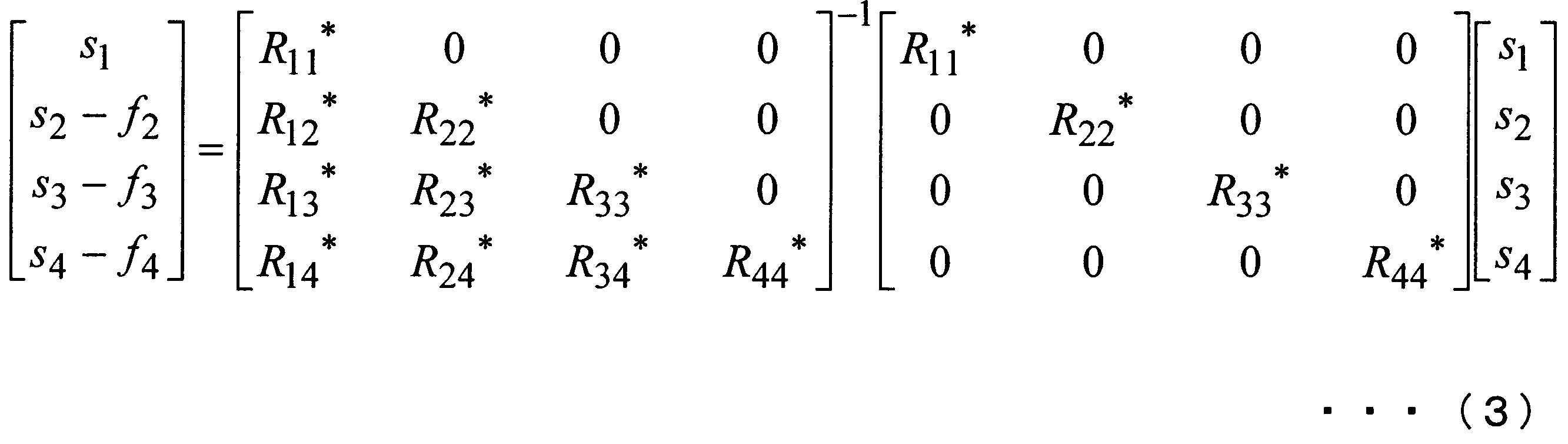
Modulo演算部a145-mは、次式(4)で表されるModulo演算を行う。

ここで、Re[u]、およびIm[u]はそれぞれ複素数uの実部、虚部を表している。床関数演算は、w以上の最小の整数を表している。jはj2=-1となる虚数単位である。なお、式(4)の第2項目、第3項目は、uの実部と虚部の大きさがτの整数倍であることを示している。なお、τは信号smに施された変調の変調方式によって決まる定数である。例えば、QPSK(Quadrature Phase-Shift Keying;四位相偏移変調)ではτ=2√2、16QAM(Quadrature Amplitude modulation;直交振幅変調)では、τ=8/√10、64QAMではτ=16/√42である。
基地局装置a1は、Modulo演算を行うことにより、干渉減算後の信号の振幅を所定の幅に収めるように送信信号の振幅を制限することができ、送信電力の増大を抑えることができる。
Modulo演算部a145-mが出力する信号は、例えば、信号s2’が次式(5)で表される。
基地局装置a1は、Modulo演算を行うことにより、干渉減算後の信号の振幅を所定の幅に収めるように送信信号の振幅を制限することができ、送信電力の増大を抑えることができる。
Modulo演算部a145-mが出力する信号は、例えば、信号s2’が次式(5)で表される。

伝搬路行列Hにフィルタ係数を乗算すると、次式(6)となる。

式(6)は、基地局装置a1と端末装置b1の間の、フィルタ係数も含めた等価的な伝搬路を表す。なお、フィルタ算出部a142のフィルタ係数の算出処理は、QR分解でなくてもよい。つまり、フィルタ算出部a142は、伝搬路行列Hに乗じた場合に三角行列になる行列をフィルタ係数として算出すればよい。
各端末装置Bmでの受信信号ymは、プレコーディング決定部a123が決定したプレコーディングに応じて、以下のようになる。
受信品質の差が閾値より大きいと判定され、プレコーディングをQR-THPに決定した場合、受信信号ymを成分とする受信信号ベクトルy=(y1,y2,y3,y4)は次式(7)で表される。
受信品質の差が閾値より大きいと判定され、プレコーディングをQR-THPに決定した場合、受信信号ymを成分とする受信信号ベクトルy=(y1,y2,y3,y4)は次式(7)で表される。
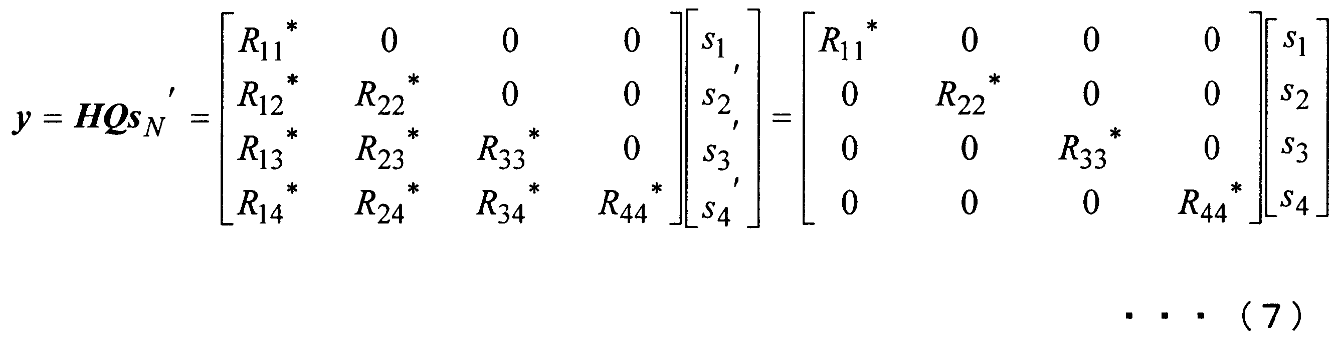
ここで、QR分解の性質からR44<R33<R22<R11である。前述のように、演算順序選択部a141は、受信品質が低い順序に信号Snを並び替えている。これにより、基地局装置a1は、mの値が小さく受信品質が低い端末装置Bm宛の信号smの振幅を大きくし、mの値が大きく受信品質が高い端末装置Bm宛の信号smの振幅を小さくすることができる。また、式(7)は、受信信号ymでは、他の端末装置宛の信号からの干渉が除去されることを示す。
一方、受信品質の差が閾値より小さいと判定され、プレコーディングをZF-THPに決定した場合、受信信号ベクトルyは次式(8)で表される。
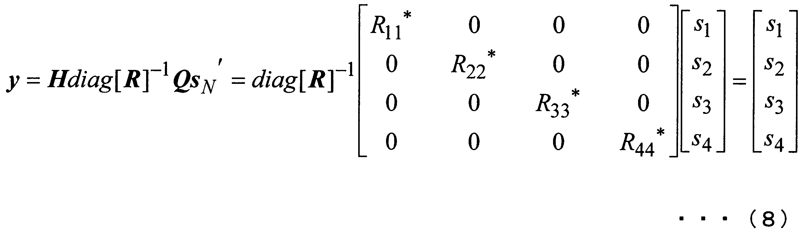
式(8)と式(7)とを比較すると、式(7)では信号smにRmmが乗算されているのに対し、式(8)では信号smにRmmが乗算されていない。これにより、基地局装置a1は、端末装置Bm宛の信号smの振幅を同程度の大きさにすることができる。
以上により、基地局装置a1は、基地局からの距離が同程度の複数の端末宛の信号を空間多重する場合にはZF-THPを、基地局からの距離が大きく異なる複数の端末宛の信号を空間多重する場合にはQR-THPを用いることにより、端末装置Bmでの受信品質の差に関わらず、端末装置Bmが受信する信号ymの振幅を同程度の大きさにすることができ、全ての端末装置で受信品質を同程度に保つことができる。つまり、基地局装置a1は、複数の端末装置における受信品質を柔軟に制御できる。
以上により、基地局装置a1は、基地局からの距離が同程度の複数の端末宛の信号を空間多重する場合にはZF-THPを、基地局からの距離が大きく異なる複数の端末宛の信号を空間多重する場合にはQR-THPを用いることにより、端末装置Bmでの受信品質の差に関わらず、端末装置Bmが受信する信号ymの振幅を同程度の大きさにすることができ、全ての端末装置で受信品質を同程度に保つことができる。つまり、基地局装置a1は、複数の端末装置における受信品質を柔軟に制御できる。
<端末装置b1について>
図3は、本実施形態に係る端末装置b1の構成を示す概略ブロック図である。この図において、端末装置b1は、受信アンテナb111(Bn1)、無線部b112、信号分離部b113、制御信号処理部b114、伝搬路推定部b115、伝搬路補償部b116、剰余判定部b117、Modulo演算部b118、復調部b119、復号部b120、上位層部b121、無線部b122、及び、送信アンテナb123を含んで構成される。
図3は、本実施形態に係る端末装置b1の構成を示す概略ブロック図である。この図において、端末装置b1は、受信アンテナb111(Bn1)、無線部b112、信号分離部b113、制御信号処理部b114、伝搬路推定部b115、伝搬路補償部b116、剰余判定部b117、Modulo演算部b118、復調部b119、復号部b120、上位層部b121、無線部b122、及び、送信アンテナb123を含んで構成される。
無線部b112は、受信アンテナb111を介して信号を受信する(端末装置Bmが受信する信号が受信信号ym)。この信号には、パイロット信号、端末装置Bm宛の情報の信号、及び、制御情報の信号が含まれている。無線部b112は、受信した信号をダウンコンバートしてベースバンド信号を生成し、A/D(Analog to Digital)変換する。無線部b112は、変換後の信号を信号分離部b113に出力する。
信号分離部b113は、無線部b112から入力された信号を分離し、制御情報の信号を制御情報受信部b113に出力し、パイロット信号を伝搬路推定部b115に出力する。信号分離部b113は、分離した信号のうち、自装置宛の情報の信号を伝搬路補償部b116に出力する。
制御信号処理部b114は、信号分離部b113から入力された制御情報の信号を復調及び復号する。制御信号処理部b114は、復号した制御情報のうち、剰余演算情報及び変調方式を、それぞれ、剰余判定部b117及びModulo演算部b118に出力する。なお、制御信号処理部b114は、復号した制御情報のうち、符号化率及び変調方式の情報を、それぞれ復調部b119及び復号部b120に出力する(図示せず)。
制御信号処理部b114は、信号分離部b113から入力された制御情報の信号を復調及び復号する。制御信号処理部b114は、復号した制御情報のうち、剰余演算情報及び変調方式を、それぞれ、剰余判定部b117及びModulo演算部b118に出力する。なお、制御信号処理部b114は、復号した制御情報のうち、符号化率及び変調方式の情報を、それぞれ復調部b119及び復号部b120に出力する(図示せず)。
伝搬路推定部b115は、信号分離部b113から入力されたパイロット信号のうち、第2の参照信号生成部a151が生成したパイロット信号に基づいて、アンテナ毎の伝搬路推定値を推定する。また、伝搬路推定部b115は、このパイロット信号を用いて受信品質の測定を行う。なお、この測定は、データ信号とは異なるフレームで送信されたパイロット信号を用いて行ってもよい。伝搬路推定部b115は、推定した伝搬路推定値を示す伝搬路情報、及び測定した受信品質を示す受信品質情報を上位層部b121に出力する。
伝搬路推定部b115は、信号分離部b113から入力されたパイロット信号のうち、第1の参照信号生成部a152が生成したパイロット信号に基づいて、自装置宛の信号が経由した等価伝搬路(基地局装置a1で乗算されたフィルタ係数も含めた伝搬路)の伝搬路推定値を推定する。伝搬路推定部b115は、推定した等価伝搬路の伝搬路推定値を示す等価伝搬路推定情報を、伝搬路補償部b116に出力する。
伝搬路補償部b116は、伝搬路推定部b115から入力された等価伝搬路推定情報が示す伝搬路推定値に応じて信号を除算することによって、伝搬路補償する。伝搬路補償部b116は、伝搬路補償した信号を剰余判定部b117に出力する。
伝搬路補償部b116は、伝搬路推定部b115から入力された等価伝搬路推定情報が示す伝搬路推定値に応じて信号を除算することによって、伝搬路補償する。伝搬路補償部b116は、伝搬路補償した信号を剰余判定部b117に出力する。
剰余判定部b117は、制御信号処理部b114から剰余演算情報が入力された場合、伝搬路補償部b116から入力された信号をModulo演算部b118に出力する。一方、剰余判定部b117は、制御信号処理部b114から剰余演算情報が入力されなかった場合、伝搬路補償部b116から入力された信号を復調部b119に出力する。この構成により、端末装置B1の剰余判定部b117は入力された信号を復調部b119に出力し、端末装置B2、B3、B4の剰余判定部b117は入力された信号をModulo演算部b118に出力することとなる。
Modulo演算部b118は、基地局装置a1と同じModulo演算(式(4)で表されるModulo演算)を行う。ここで、Modulo演算部b118は、制御信号処理部b114から入力された情報が示す変調方式に対応するτを選択し、そのτを用いてModulo演算を行う。Modulo演算部b118は、演算後の信号を復調部b119に出力する。
Modulo演算部b118は、基地局装置a1と同じModulo演算(式(4)で表されるModulo演算)を行う。ここで、Modulo演算部b118は、制御信号処理部b114から入力された情報が示す変調方式に対応するτを選択し、そのτを用いてModulo演算を行う。Modulo演算部b118は、演算後の信号を復調部b119に出力する。
復調部b119は、剰余判定部b117又はModulo演算部b118から入力された信号を、制御信号処理部b114から入力された情報が示す変調方式を用いて復調する。復調部b119は、信号を復調した情報を復号部b120に出力する。
復号部b120は、復調部b119から入力された情報を、制御信号処理部b114から入力された情報が示す符号化率に基づいて、復号する。復調部b119は、復号した情報を上位層部b121に出力する。
復号部b120は、復調部b119から入力された情報を、制御信号処理部b114から入力された情報が示す符号化率に基づいて、復号する。復調部b119は、復号した情報を上位層部b121に出力する。
上位層部b121は、復号部b120から入力された情報を出力部(図示せず)に出力し、又は情報に基づいて端末装置b1を制御する。上位層部b121は、伝搬路推定部b115から入力された受信品質情報及び伝搬路情報を、基地局装置a1宛の信号として無線部b122に出力する。
無線部b122は、上位層部b121から入力された情報を変調し、変調した信号をD/A変換する。無線部b122は、変換後の信号を、無線周波数にアップコンバートし、送信アンテナb123を介して、基地局装置a1に送信する。
無線部b122は、上位層部b121から入力された情報を変調し、変調した信号をD/A変換する。無線部b122は、変換後の信号を、無線周波数にアップコンバートし、送信アンテナb123を介して、基地局装置a1に送信する。
このように、本実施形態では、基地局装置a1は、複数の端末装置Bm宛の信号を空間多重するためのプレコーディングを、複数のプレコーディング(ZF-THP、QR-THP)から選択し、選択したプレコーディングを行った信号を送信する。これにより、通信システムは、受信品質が異なることとなる複数のプレコーディングからプレコーディングを選択でき、複数の端末装置Bmにおける受信品質を柔軟に制御できる。
また、本実施形態では、ZF-THPは、複数の端末装置Bm宛の信号各々に同じ値「1」が乗算される(又は値が乗算されないもの)である(式(8)参照)。基地局装置a1は、複数の端末装置Bm宛での受信品質の差が予め定めた値より小さい場合には、ZF-THPを選択する。これにより、端末装置Bmは、複数の端末装置Bmでの受信品質が同程度である場合には、そのまま受信品質が同程度になるように、信号を受信することができる。
一方、QR-THPは、複数の端末装置Bm宛の信号各々に異なる値が乗算されるものである(式(3)参照)。基地局装置a1は、複数の端末装置Bm宛での受信品質の差が予め定めた値より大きい場合には、QR-THPを選択する。これにより、端末装置Bmは、複数の端末装置Bmでの受信品質に大きな差がある場合には、各端末装置Bmでの受信品質が同程度になるように、信号を受信することができる。
一方、QR-THPは、複数の端末装置Bm宛の信号各々に異なる値が乗算されるものである(式(3)参照)。基地局装置a1は、複数の端末装置Bm宛での受信品質の差が予め定めた値より大きい場合には、QR-THPを選択する。これにより、端末装置Bmは、複数の端末装置Bmでの受信品質に大きな差がある場合には、各端末装置Bmでの受信品質が同程度になるように、信号を受信することができる。
なお、本実施形態では、各端末装置Bnの受信品質情報に基づいてプレコーディングを選択する場合について説明をした。しかし、基地局装置a1は、受信品質情報及び各端末装置宛の情報のデータ量に基づいてプレコーディングを選択してもよい。例えば、基地局装置a1は、受信品質の差が閾値より小さいと判定した場合でも、各端末装置宛の情報のデータ量の差が予め定めた閾値以上となる場合には、QR-THPを選択してもよい。
この場合、基地局装置a1(演算順序選択部a141)は、データ量がm番目に多い端末装置Bn宛の信号Snを信号smとする。これにより、基地局装置a1は、データ量の多い端末装置Bm宛の信号の受信品質を高くして、確実に信号を送信することができる。換言すれば、基地局装置a1は、データ量が多い方に誤りが発生することで再送が頻発し、伝送効率の悪化や処理負荷の増加を防止することができる。
また、この場合、データ量が多い端末装置宛の情報を変調多値数の高い変調方式(例えば、16QAM)で変調し、データ量が少ない端末装置宛の情報を変調多値数の小さい変調方式(例えば、QPSK)で変調してもよい。
また、本実施形態において、基地局装置a1は、QR分解を用いてプレコーディングを行う場合について説明をした。しかし、本発明はこれに限らず、伝搬路行列の逆行列に基づいてフィルタ係数を生成するプレコーディングを用いてもよいし、送信信号と各端末装置における受信信号の平均二乗誤差が最小となるようにMMSE規範によりフィルタ係数を算出するプレコーディングを用いてもよい。
この場合、基地局装置a1(演算順序選択部a141)は、データ量がm番目に多い端末装置Bn宛の信号Snを信号smとする。これにより、基地局装置a1は、データ量の多い端末装置Bm宛の信号の受信品質を高くして、確実に信号を送信することができる。換言すれば、基地局装置a1は、データ量が多い方に誤りが発生することで再送が頻発し、伝送効率の悪化や処理負荷の増加を防止することができる。
また、この場合、データ量が多い端末装置宛の情報を変調多値数の高い変調方式(例えば、16QAM)で変調し、データ量が少ない端末装置宛の情報を変調多値数の小さい変調方式(例えば、QPSK)で変調してもよい。
また、本実施形態において、基地局装置a1は、QR分解を用いてプレコーディングを行う場合について説明をした。しかし、本発明はこれに限らず、伝搬路行列の逆行列に基づいてフィルタ係数を生成するプレコーディングを用いてもよいし、送信信号と各端末装置における受信信号の平均二乗誤差が最小となるようにMMSE規範によりフィルタ係数を算出するプレコーディングを用いてもよい。
(第2の実施形態)
以下、図面を参照しながら本発明の第2の実施形態について詳しく説明する。
本実施形態では、端末装置が複数の受信アンテナを備え、基地局装置が端末装置に対して複数のストリームの信号を送信する場合について説明をする。
以下、図面を参照しながら本発明の第2の実施形態について詳しく説明する。
本実施形態では、端末装置が複数の受信アンテナを備え、基地局装置が端末装置に対して複数のストリームの信号を送信する場合について説明をする。
図4は、本発明の第2の実施形態に係る通信システムの一例を示す概略図である。この図において、通信システムは、基地局装置a2と複数の端末装置B1~BNを具備する。なお、図4ではN=2であり、本実施形態ではN=2とするが、本発明はこれに限らず、N>2であってもよい。基地局装置a2は、4本の送信アンテナa161~a164を備える。
基地局装置a2は、同一時刻で同一周波数を用いて2個の端末装置B1、B2宛の信号を空間多重して送信する。端末装置Bn(n=1~N;端末装置Bn各々を端末装置b2ともいう)は、Jn本の受信アンテナBn1~BnJnを備え、基地局装置a2から送信された信号を受信する。なお、図4ではJ1、J2=2であり、本実施形態ではJ1、J2=2とするが、本発明はこれに限らず、J1<2、J1>2であってもJ2<2、J2>2であってもよい。また、J1=J2でなくてもよい。
ここで、端末装置B1~BNは、それぞれ、基地局装置a2との距離が異なるため、基地局装置a2から送信された信号の受信品質が異なる。
基地局装置a2は、同一時刻で同一周波数を用いて2個の端末装置B1、B2宛の信号を空間多重して送信する。端末装置Bn(n=1~N;端末装置Bn各々を端末装置b2ともいう)は、Jn本の受信アンテナBn1~BnJnを備え、基地局装置a2から送信された信号を受信する。なお、図4ではJ1、J2=2であり、本実施形態ではJ1、J2=2とするが、本発明はこれに限らず、J1<2、J1>2であってもJ2<2、J2>2であってもよい。また、J1=J2でなくてもよい。
ここで、端末装置B1~BNは、それぞれ、基地局装置a2との距離が異なるため、基地局装置a2から送信された信号の受信品質が異なる。
MU-MIMO伝送では、端末装置B1~BNへの信号間で干渉が生じる。基地局装置a2は、ある端末装置宛の信号に対して、他の端末装置宛の信号による干渉を除去するように、予めプレコーディングを施して伝送する。ここで、基地局装置a2は、複数のプレコーディングのうち1つを選択して、そのプレコーディングを用いる。
なお、本実施形態では、端末装置Bnが同じ本数(2本)の受信アンテナを備える場合について説明するが、本発明はこれに限らず、端末装置Bnの受信アンテナ数は異なっていてもよい。
なお、本実施形態では、端末装置Bnが同じ本数(2本)の受信アンテナを備える場合について説明するが、本発明はこれに限らず、端末装置Bnの受信アンテナ数は異なっていてもよい。
図5は、本実施形態に係る基地局装置a2の構成を示す概略ブロック図である。本実施形態に係る基地局装置a2(図5)と第1の実施形態に係る基地局装置a1(図2)とを比較すると、上位層部a22のプレコーディング決定部a223、及び多重信号生成部a24が異なる。しかし、他の構成要素(受信アンテナa111、無線部a112、アプリケーション部a121、受信品質取得部a122、符号化部a131-1~a131-I(I=ΣJn。ΣJnは端末装置の受信アンテナの総数であり、本実施形態では「4」)、変調部a132-1~a132-I、第2の参照信号生成部a151、第1の参照信号生成部a152、フィルタ乗算部a153、信号多重部a154、無線部a155-1~a155-4、送信アンテナa161~a164)が持つ機能は第1の実施形態と同じである。第1の実施形態と同じ機能の説明は省略する。
多重信号生成部a24は、プレコーディング選択部a240、第1のプレコーディング部a24-1、及び第2のプレコーディング部a24-2を含んで構成される。
多重信号生成部a24は、プレコーディング選択部a240、第1のプレコーディング部a24-1、及び第2のプレコーディング部a24-2を含んで構成される。
プレコーディング決定部a223は、受信品質の差が閾値より小さいと判定した場合には、プレコーディングをBD(Block Diagonalization)に決定する。つまり、プレコーディング決定部a223は、端末装置Bn間の受信品質に大きな差がなく、受信品質が同程度である場合には、プレコーディングをBDに決定することとなる。一方、プレコーディング決定部a223は、受信品質の差が閾値以上であると判定した場合には、プレコーディングをBT(Block Trianglization)-THPに決定する。つまり、プレコーディング決定部a223は、端末装置Bn間の受信品質に大きな差(例えば、受信SNRが5dB)があり、受信品質に偏りがある場合には、プレコーディングをBT-THPに決定することとなる。
プレコーディング決定部a223は、決定したプレコーディングを示すプレコーディング情報を、プレコーディング選択部a240に出力する。また、プレコーディング決定部a223は、プレコーディング情報を符号化及び変調して信号多重部a154に出力する。出力されたプレコーディング情報の信号は、信号多重部a154で多重され、各端末装置b2に送信される。
プレコーディング決定部a223は、決定したプレコーディングを示すプレコーディング情報を、プレコーディング選択部a240に出力する。また、プレコーディング決定部a223は、プレコーディング情報を符号化及び変調して信号多重部a154に出力する。出力されたプレコーディング情報の信号は、信号多重部a154で多重され、各端末装置b2に送信される。
プレコーディング選択部a240は、変調部a132-i(i=1~I)各々から変調後の信号Siであって、端末装置Bnの受信アンテナBnj(j=1~Jn)宛の信号Siを入力される。ここで、iはi=j+Σs≦n-1Jsであり、第2項は端末装置Bs(sはn-1以下)の受信アンテナの総数Jsについて和をとることを示す。
プレコーディング選択部a240は、プレコーディング決定部a223から入力されたプレコーディング情報がBDを示す場合には、入力された信号Si及び、受信品質情報を第1のプレコーディング部a24-1に出力する。
一方、プレコーディング選択部a240は、プレコーディング決定部a223から入力されたプレコーディング情報がBT-THPを示す場合には、入力された信号Si及び受信品質情報を第2のプレコーディング部a24-2に出力する。
プレコーディング選択部a240は、プレコーディング決定部a223から入力されたプレコーディング情報がBDを示す場合には、入力された信号Si及び、受信品質情報を第1のプレコーディング部a24-1に出力する。
一方、プレコーディング選択部a240は、プレコーディング決定部a223から入力されたプレコーディング情報がBT-THPを示す場合には、入力された信号Si及び受信品質情報を第2のプレコーディング部a24-2に出力する。
図6は、本実施形態に係る第1のプレコーディング部a24-1の構成を示す概略ブロック図である。この図において、第1のプレコーディング部a24-1は、フィルタ算出部a24-12、及びフィルタ乗算部a246を含んで構成される。
フィルタ算出部a24-12は、無線部a112から入力された伝搬路情報から伝搬行列Hを生成する。ここで、伝搬行列Hのn行k列要素Hlk(k=1~N)は、基地局装置a2の送信アンテナa16kと、端末装置Bnの受信アンテナBnjとの間の伝搬路推定値である。フィルタ算出部a24-12は、生成した伝搬行列Hに乗算した場合に、その行列がブロック対角化される行列Mを算出する。ここで、ブロック対角化とは、行列成分を端末装置b2毎の要素(ブロックという)とした場合に、ブロックでの対角成分(対角ブロックという)以外の成分(非対角ブロックという)が0であることをいう(式(13)参照)。フィルタ算出部a24-12は、算出した行列Mをフィルタ係数としてフィルタ乗算部a246及びフィルタ乗算部a153に出力する。
フィルタ乗算部a246は、プレコーディング選択部a240から入力された信号Si(以下、信号si’と称する)を成分とするベクトルsi’=(s1’,s2’,・・・,sI’)Tを生成する。フィルタ乗算部a246は、フィルタ算出部a142から入力された情報が示すフィルタ係数に、生成したベクトルsi’を乗算する。フィルタ乗算部a246は、乗算後のベクトルの成分の信号を、信号多重部a154に出力する。なお、信号多重部a154は、信号si’から生成されて出力された信号を、送信アンテナa16iで送信する帯域に配置する。
図7は、本実施形態に係る第2のプレコーディング部a24-2の構成を示す概略ブロック図である。この図において、第2のプレコーディング部a24-2は、演算順序選択部a24-21、フィルタ算出部a24-22、干渉算出部a24-23、減算部a144-3(=J+1)~a144-4(=I)、Modulo演算部a145-3~a145-4、及びフィルタ乗算部a246を含んで構成される。
ここで、減算部a144-3~a144-4、Modulo演算部a145-3~a145-4が持つ機能は、第1の実施形態のものと同じであるので、説明は省略する。また、フィルタ乗算部a246が持つ機能は、第1のプレコーディング部(図6)とはフィルタ係数が異なるが同様な機能であるので、説明は省略する。
ここで、減算部a144-3~a144-4、Modulo演算部a145-3~a145-4が持つ機能は、第1の実施形態のものと同じであるので、説明は省略する。また、フィルタ乗算部a246が持つ機能は、第1のプレコーディング部(図6)とはフィルタ係数が異なるが同様な機能であるので、説明は省略する。
演算順序選択部a24-21は、受信品質取得部a122から入力された受信品質情報に基づいて、変調部a132-iから入力された信号Siの出力先を選択する。具体的には、演算順序選択部a24-21は、受信品質情報が示す受信品質がm番目(m=1~N-1)に低い端末装置Bnのj番目の受信アンテナ宛の信号Siを信号siとする。演算順序選択部a141は、信号s1、s2をフィルタ乗算部a246と干渉算出部a24-23に出力し、信号si(i≧3)をそれぞれ減算部a144-iに出力する。
フィルタ算出部a24-22は、無線部a112から入力された伝搬路情報から伝搬行列Hを生成する。フィルタ算出部a24-22は、生成した伝搬行列Hに乗算した場合に、その行列が下方にブロック三角化される行列Mを算出する。ここで、ブロック三角化とは、行列成分を端末装置b2毎の要素(ブロック)とした場合に、ブロックでの非対角成分(非対角ブロックという)の一方の行列が0であることをいう(式(23)参照)。フィルタ算出部a24-22は、算出した行列Mをフィルタ係数としてフィルタ乗算部a246及びフィルタ乗算部a153に出力する。
フィルタ算出部a24-22は、伝搬行列Hに行列Mを乗算した結果の行列Aを示す情報を、干渉算出部a24-23に出力する。
フィルタ算出部a24-22は、伝搬行列Hに行列Mを乗算した結果の行列Aを示す情報を、干渉算出部a24-23に出力する。
干渉算出部a24-23は、フィルタ算出部a24-22から入力された情報が示す行列Aを用いて、プレコーディング選択部a240から入力された信号Si(以下、信号siと称する)に対する他の端末装置からの干渉信号fiを逐次生成する。具体的には、干渉算出部a24-23は、行列Aを用いて、干渉係数行列C={Diag(A)}-1A-Iを算出する。ここで、Diag(X)は、行列Xの非対角ブロックを0とした行列を表す。
干渉算出部a24-23は、プレコーディング選択部a240から入力された信号siを成分とするベクトルsi’を逐次生成する。
干渉算出部a24-23は、干渉係数行列Cにベクトルsi’を乗算することで、干渉信号fiを生成する。つまり、干渉算出部a142は、干渉信号f3は、干渉係数行列Cに(s1,s2,0,0)Tを乗算した行列のうち第3成分、干渉信号f4は、干渉係数行列Cに(s1,s2,0,0)Tを乗算した行列のうち第4成分を生成する。
なお、図7の一例では、干渉算出部a24-23は、信号siを成分とするベクトルsI’のみ生成することとなるが、端末装置がN個以上ある場合には、Modulo演算部a145-(J1+1)~a145-(I―JN)から信号sJ1+1~sI―JNを入力されてもよい。ここでJ1は端末装置B1の受信アンテナの本数であり、JNは端末装置BNの受信アンテナの本数である。この場合、干渉算出部a24-23は、信号si及び信号sJ1+1~sI―JNを成分とするベクトルsI’を逐次生成する。
干渉算出部a24-23は、生成した干渉信号fiを、それぞれ、減算部a144-iに出力する。
干渉算出部a24-23は、干渉係数行列Cにベクトルsi’を乗算することで、干渉信号fiを生成する。つまり、干渉算出部a142は、干渉信号f3は、干渉係数行列Cに(s1,s2,0,0)Tを乗算した行列のうち第3成分、干渉信号f4は、干渉係数行列Cに(s1,s2,0,0)Tを乗算した行列のうち第4成分を生成する。
なお、図7の一例では、干渉算出部a24-23は、信号siを成分とするベクトルsI’のみ生成することとなるが、端末装置がN個以上ある場合には、Modulo演算部a145-(J1+1)~a145-(I―JN)から信号sJ1+1~sI―JNを入力されてもよい。ここでJ1は端末装置B1の受信アンテナの本数であり、JNは端末装置BNの受信アンテナの本数である。この場合、干渉算出部a24-23は、信号si及び信号sJ1+1~sI―JNを成分とするベクトルsI’を逐次生成する。
干渉算出部a24-23は、生成した干渉信号fiを、それぞれ、減算部a144-iに出力する。
<多重信号生成部a24での処理について>
上記の構成により、多重信号生成部a24での処理は、以下の処理となる。
フィルタ算出部a24-12、a24-22は、式(1)の伝搬行列Hを生成する。なお、伝搬行列Hの行成分iはi=j+Σs≦n-1Jsである。
フィルタ算出部a24-12、a24-22は、伝搬行列Hを端末装置n毎に抽出する(伝搬行列Hnという)。具体的には、フィルタ算出部a24-12、a24-22は、次式(9)、(10)を抽出する。
上記の構成により、多重信号生成部a24での処理は、以下の処理となる。
フィルタ算出部a24-12、a24-22は、式(1)の伝搬行列Hを生成する。なお、伝搬行列Hの行成分iはi=j+Σs≦n-1Jsである。
フィルタ算出部a24-12、a24-22は、伝搬行列Hを端末装置n毎に抽出する(伝搬行列Hnという)。具体的には、フィルタ算出部a24-12、a24-22は、次式(9)、(10)を抽出する。

BDの場合、フィルタ算出部a24-12は、伝搬行列Hnを特異値分解(SVD:Singular Value Decomposition)する。具体的には、フィルタ算出部a24-12は、次式(11)で表される各行列Un’、Dn’、Vn’Hを算出する。

ここで、行列Un’はJn行Jn列のユニタリ行列であり、行列Dn’はJn行K列で対角成分以外は0、対角成分は非負の行列である。行列Vn’HはK行K列のユニタリ行列である。このように、行列を分解することを特異値分解という。この行列Vn’Hを用いることにより、通信システムでは、端末装置Bn宛の信号を、他の端末装置に届かないようにすることができる。
フィルタ算出部a24-12は、行列Vn’Hの右半分(3、4列)である4行2列の行列(Vn,2とする)を抽出する。フィルタ算出部a24-12は、この行列Vn,2を用いて、次式(12)の行列M’を算出する。
フィルタ算出部a24-12は、行列Vn’Hの右半分(3、4列)である4行2列の行列(Vn,2とする)を抽出する。フィルタ算出部a24-12は、この行列Vn,2を用いて、次式(12)の行列M’を算出する。

基地局装置において送信信号に式(12)のプレコーディングを行って送信し、伝搬路を通ると、端末装置側から見ると行列M’に伝搬路行列Hを乗算された伝搬路と等価な伝搬路となり、次式(13)となる。

式(13)は、行列Mを乗算した信号が伝搬路を介して受信された場合に、他の端末装置宛の信号から干渉を受けないことを示す。つまり、式(13)が示す伝搬路は、2つのSU-MIMO(Single User―MIMO)伝搬路となる。フィルタ算出部a24-12は、H1,1及びH2,2を、それぞれ、次式(16)、(17)のように、特異値分解する。

ここで、行列Un,nは2行2列のユニタリ行列であり、行列Dnは2行2列で対角成分以外は0、対角成分は非負の行列である。行列Vnは2行2列のユニタリ行列である。である。フィルタ算出部a24-12は、行列Mを、次式(18)によって算出する。

フィルタ乗算部a246は、BDの場合、式(18)の行列Mをフィルタ係数として、信号に乗算する。
BT-THPの場合、フィルタ算出部a24-22は、式(19)のように、伝搬行列H1を特異値分解する。
なお、本実施形態では、フィルタ係数として式(18)を用いる場合について説明をしたが、本発明はこれに限らず、フィルタ算出部a24-12が算出するフィルタ係数は、伝搬路行列Hを乗算したときに、乗算後の行列をブロック対角化するフィルタ係数であればよい。
なお、本実施形態では、フィルタ係数として式(18)を用いる場合について説明をしたが、本発明はこれに限らず、フィルタ算出部a24-12が算出するフィルタ係数は、伝搬路行列Hを乗算したときに、乗算後の行列をブロック対角化するフィルタ係数であればよい。

ここで、行列V1は4行4列のユニタリ行列である。フィルタ算出部a24-22は、行列V1は行列V1の左半分(1、2列)である4行2列の行列と、左半分(3、4列)である4行2列の行列をそれぞれ行列V1,1と行列V1,2として抽出する。フィルタ算出部a24-22は、行列V1,2に行列H2を乗算した行列を特異値分解することで、行列V2’を算出する。具体的には、フィルタ算出部a24-22は、次式(20)、(21)を満たすV2’を算出する。

フィルタ算出部a24-22は、行列Mを、次式(22)によって算出する。

フィルタ乗算部a246は、BT-THPの場合、式(22)の行列Mをフィルタ係数として、信号に乗算する。
基地局装置において送信信号に式(22)のプレコーディングを行って送信され、伝搬路を介して受信された信号は、端末装置側では、式(22)の行列Mに伝搬路行列Hを乗算された伝搬路と等価な伝搬路を介したものと同じなる。この等価な伝搬路は、次式(23)となる。
基地局装置において送信信号に式(22)のプレコーディングを行って送信され、伝搬路を介して受信された信号は、端末装置側では、式(22)の行列Mに伝搬路行列Hを乗算された伝搬路と等価な伝搬路を介したものと同じなる。この等価な伝搬路は、次式(23)となる。

式(23)は、基地局装置a2と端末装置b2の間の、フィルタ係数も含めた等価的な伝搬路を表す。また、式(23)は、ブロック三角化されていることを示す。なお、本実施形態では、フィルタ係数として式(23)を用いる場合について説明をしたが、本発明はこれに限らず、フィルタ算出部a24-22が算出するフィルタ係数は、伝搬路行列Hを乗算したときに、乗算後の行列をブロック三角化するフィルタ係数であればよい。
式(23)の非対角成分は、端末装置B1宛の信号が端末装置B2に届き、干渉信号となることを示す。干渉算出部a24-23は、この干渉信号を算出する。具体的には、干渉算出部a24-23は、次式(24)を用いて干渉信号f3、f4を算出する。

なお、この場合、次式(25)の関係が満たされる。

Modulo演算部a145-3~a145-4は、それぞれ、干渉算出部a24-23が算出した干渉信号f3、f4を信号s3、s4から減算する。これにより、式(25)の右辺に示すように、ベクトルsiに対して、ブロック対角化された行列を乗じることとなる。つまり、複数の端末装置宛の信号が互いに干渉し合わないように、空間多重を実現することができる。
<端末装置b2について>
図8は、本実施形態に係る端末装置b2の構成を示す概略ブロック図である。この図において、端末装置b2は、受信アンテナb111-1(Bn1)、b111-2(Bn2)、無線部b112-1、b112-2、信号分離部b213-1、b213-2、制御信号処理部b114-1、b114-2、伝搬路推定部b115、係数推定部b224、MIMO多重分離部b216、剰余判定部b117-1、b117-2、Modulo演算部b118-1、b118-2、復調部b119-1、b119-2、復号部b120-1、b120-2、上位層部b121、無線部b122、及び、送信アンテナb123を含んで構成される。
図8は、本実施形態に係る端末装置b2の構成を示す概略ブロック図である。この図において、端末装置b2は、受信アンテナb111-1(Bn1)、b111-2(Bn2)、無線部b112-1、b112-2、信号分離部b213-1、b213-2、制御信号処理部b114-1、b114-2、伝搬路推定部b115、係数推定部b224、MIMO多重分離部b216、剰余判定部b117-1、b117-2、Modulo演算部b118-1、b118-2、復調部b119-1、b119-2、復号部b120-1、b120-2、上位層部b121、無線部b122、及び、送信アンテナb123を含んで構成される。
なお、受信アンテナb111-1、b111-2が持つ機能は受信アンテナb111と同じであり、無線部b112-1、b112-2が持つ機能は無線部b112と同じであり、信号分離部b213-1、b213-2が持つ機能は信号分離部b113と同じである。制御信号処理部b114-1、b114-2が持つ機能は制御信号処理部b114と同じであり、剰余判定部b117-1、b117-2が持つ機能は剰余判定部b117と同じである。Modulo演算部b118-1、b118-2が持つ機能はModulo演算部b118と同じであり、復調部b119-1、b119-2が持つ機能は復調部b119と同じであり、復号部b120-1、b120-2が持つ機能は復号部b120と同じである。また、伝搬路推定部b115、上位層部b121及び無線部b122が持つ機能は、第1の実施形態のものと同じである。これらの機能については、説明を省略する。
係数推定部b224には、信号分離部b213-1及びb213-2から、プレコーディング情報の信号及びパイロット信号が入力される。係数推定部b224は、プレコーディング情報の信号を復調及び復号する。
復号したプレコーディング情報がBDを示す場合、係数推定部b224は、式(18)のフィルタ係数を算出してMIMO多重分離部b216に出力する。一方、復号したプレコーディング情報がBT-THPを示す場合、係数推定部b224は、式(22)のフィルタ係数を算出してMIMO多重分離部b216に出力する。また、係数推定部b224には、プレコーディング情報をMIMO多重分離部b216に出力する。
復号したプレコーディング情報がBDを示す場合、係数推定部b224は、式(18)のフィルタ係数を算出してMIMO多重分離部b216に出力する。一方、復号したプレコーディング情報がBT-THPを示す場合、係数推定部b224は、式(22)のフィルタ係数を算出してMIMO多重分離部b216に出力する。また、係数推定部b224には、プレコーディング情報をMIMO多重分離部b216に出力する。
端末装置BnのMIMO多重分離部b216は、伝搬路推定部b115から入力された伝搬路情報に基づいて、伝搬行列Hnを生成する。MIMO多重分離部b216は、生成した伝搬行列Hn及び係数推定部b224から入力されたフィルタ係数に基づいて、信号を抽出する。
具体的には、係数推定部b224から入力されたプレコーディング情報がBDを示す場合、MIMO多重分離部b216は、式(16)、(17)の行列Un,nを算出する。一方、係数推定部b224から入力されたプレコーディング情報がBT-THPを示す場合、MIMO多重分離部b216は、式(19)の行列U1(端末装置B1の場合)、又は、式(21)の行列U2’(端末装置B2の場合)を算出する。なお、基地局装置b2は、各端末装置が端末装置B1であるか又はB2であるかを示す情報を、各端末装置に対して予め送信し、MIMO多重分離部b216は、この情報に基づいて行列U1又はU2’を算出してもよい。
MIMO多重分離部b216は、算出した行列Un,n、行列U1又は行列U2’を信号分離部b213-1、b213-2から入力された信号に乗算する。例えば、プレコーディング情報がBT-THPを示す場合の端末装置B2では、式(24)の行列の積HMにU2’を乗算した行列は、D2’(対角行列)となるので、MIMO多重分離部b216は、D2’を除算することで信号を抽出する。以上のように、MIMO多重分離部b216は、各ストリームの信号を抽出する。MIMO多重分離部b216は、抽出した信号を、受信アンテナb111-1、b111-2毎にそれぞれ剰余判定部b117-1、b117-2に出力する。
具体的には、係数推定部b224から入力されたプレコーディング情報がBDを示す場合、MIMO多重分離部b216は、式(16)、(17)の行列Un,nを算出する。一方、係数推定部b224から入力されたプレコーディング情報がBT-THPを示す場合、MIMO多重分離部b216は、式(19)の行列U1(端末装置B1の場合)、又は、式(21)の行列U2’(端末装置B2の場合)を算出する。なお、基地局装置b2は、各端末装置が端末装置B1であるか又はB2であるかを示す情報を、各端末装置に対して予め送信し、MIMO多重分離部b216は、この情報に基づいて行列U1又はU2’を算出してもよい。
MIMO多重分離部b216は、算出した行列Un,n、行列U1又は行列U2’を信号分離部b213-1、b213-2から入力された信号に乗算する。例えば、プレコーディング情報がBT-THPを示す場合の端末装置B2では、式(24)の行列の積HMにU2’を乗算した行列は、D2’(対角行列)となるので、MIMO多重分離部b216は、D2’を除算することで信号を抽出する。以上のように、MIMO多重分離部b216は、各ストリームの信号を抽出する。MIMO多重分離部b216は、抽出した信号を、受信アンテナb111-1、b111-2毎にそれぞれ剰余判定部b117-1、b117-2に出力する。
このように、本実施形態では、基地局装置a1は、複数の端末装置Bn宛の信号を空間多重するためのプレコーディングを、複数のプレコーディング(BD、BT-THP)から選択し、選択したプレコーディングを行った信号を送信する。これにより、通信システムは、受信品質が異なることとなる複数のプレコーディングからプレコーディングを選択でき、複数の端末装置Bnにおける受信品質を柔軟に制御できる。
本実施形態のように、MU-MIMOシステムにおいて、複数のプレコーディング手段を備え、それらの中からプレコーディング手段を選択して用いることにより、各種プレコーディング手段の特徴を生かしたMU-MIMO伝送が実現でき、伝送特性を向上させることが可能である。特に、空間多重の対象となる端末の組み合わせに応じてプレコーディング手段を選択することにより、状況に応じた適切なプレコーディング手段を選択することができる。
本実施形態のように、MU-MIMOシステムにおいて、複数のプレコーディング手段を備え、それらの中からプレコーディング手段を選択して用いることにより、各種プレコーディング手段の特徴を生かしたMU-MIMO伝送が実現でき、伝送特性を向上させることが可能である。特に、空間多重の対象となる端末の組み合わせに応じてプレコーディング手段を選択することにより、状況に応じた適切なプレコーディング手段を選択することができる。
なお、本実施形態では、MIMO多重分離部b216が行列Un,n、行列U1又は行列U2’を算出する場合について説明したが、本発明はこれに限られない。例えば、基地局装置a2がこれらの行列を算出し、算出した行列の情報を端末装置b2に送信してもよい。この場合、端末装置b2のMIMO多重分離部b216は、受信した行列の情報を用いて信号を抽出する。また、MIMO多重分離部b216は他の処理で信号を抽出してもよい。例えば、他の各端末装置における2つの受信信号をMMSE(Minimum Mean Square Error)やMLD(Maximum Likelihood Detection)で分離してもよい。
また、本実施形態では、剰余判定部b117-1、b117-2は、剰余演算情報に応じて出力先を選択するが、プレコーディング情報、及び端末装置B1であるか又はB2であるかを示す情報に応じて出力先を選択してもよい。例えば、プレコーディング情報がBT-THPであり、かつ、端末装置B2である場合には、剰余判定部b117-1、b117-2は、それぞれ、Modulo演算部b118-1、b118-2に出力し、この場合以外は、復調部b119-1、b119-2に出力する。
また、本実施形態では、剰余判定部b117-1、b117-2は、剰余演算情報に応じて出力先を選択するが、プレコーディング情報、及び端末装置B1であるか又はB2であるかを示す情報に応じて出力先を選択してもよい。例えば、プレコーディング情報がBT-THPであり、かつ、端末装置B2である場合には、剰余判定部b117-1、b117-2は、それぞれ、Modulo演算部b118-1、b118-2に出力し、この場合以外は、復調部b119-1、b119-2に出力する。
なお、本実施形態では、2つの端末装置の場合のフィルタ算出部の処理を説明した。しかし、本発明はこれに限らず、2つ以上の端末装置であってもよい。以下ではこの場合のフィルタ算出部の処理の一例について説明する。フィルタ算出部a24-12は、以下の処理を行う。
n番目の端末装置Bn以外の伝搬路行列をHn~(チルダ)とすると、次式で表すことができる。
n番目の端末装置Bn以外の伝搬路行列をHn~(チルダ)とすると、次式で表すことができる。

式(26)を特異値分解すると、次式のようになる。

式(27)において、左特異ベクトルUn~は端末装置側のユニタリ行列、Dn~は対角行列(特異値) 、右特異ベクトルVn~Hは基地局装置側のユニタリ行列を表している。また、Vn~HはK行K列の行列である。このとき、n番目の端末装置に対して他の端末装置からの信号が届かないようにするためのフィルタ係数をVn^(ハット)と定義すると、Vn^は、Vn^Hのうち右側のJn(n番目の端末装置の受信アンテナ数) 列を抽出した行列となる。したがって,BDにおけるブロック対角化のためのフィルタ係数をM’とすると、次式(28)のように表すことができる。

ここで、基地局装置において送信信号に式(28)のプレコーディングを行って送信し、伝搬路を通ると、端末装置側から見ると伝搬路行列Hに行列M’を乗算された伝搬路と等価な伝搬路となる。このとき各端末装置におけるSU-MIMO伝搬路をそれぞれHMn’とおき、それぞれについて次式のように、特異値分解する。

フィルタ算出部a24-12は、フィルタ係数Mを、次式(30)によって算出する。

一方、フィルタ算出部a24-22は、以下の処理を行う。BT-THPにおけるブロック三角化のためのフィルタ係数をM’とすると、次式(31)のように表すことができる。

このとき、Vn’は次式(32)のように算出する。

式(32)において、nはN、N-1、…、2の順にそれぞれのVn
’ を算出する。ここで、Hnのうちブロック三角化するために抽出する伝搬路行列をBn
T、残りの伝搬路行列をBn~(チルダ)Tと定義する。このBnを特異値分解することによって式(31)のVn
’を得る。
ここで、基地局装置a2において送信信号に式(31)のプレコーディングを行って送信し、伝搬路を通ると、端末装置Bn側から見ると伝搬路行列Hに右から行列M’を乗算された伝搬路と等価な伝搬路となる。このときHM’はブロック三角化された伝搬路行列となる。ここで、各送信アンテナと各端末装置Bnで構成される伝搬路行列を抽出する。この抽出された伝搬路行列は、対角成分に配置された基地局装置a2と各端末装置BnのシングルユーザMIMO伝搬路行列、例えば、式(25)の例では、A11、A12、A21、A22、A33、A34、A43、A44の成分以外をゼロに置き換えた行列を表している。この行列をAとし、各端末装置BnにおけるSU-MIMO伝搬路をそれぞれAn’とおくと、次式(33)のようになる。
ここで、基地局装置a2において送信信号に式(31)のプレコーディングを行って送信し、伝搬路を通ると、端末装置Bn側から見ると伝搬路行列Hに右から行列M’を乗算された伝搬路と等価な伝搬路となる。このときHM’はブロック三角化された伝搬路行列となる。ここで、各送信アンテナと各端末装置Bnで構成される伝搬路行列を抽出する。この抽出された伝搬路行列は、対角成分に配置された基地局装置a2と各端末装置BnのシングルユーザMIMO伝搬路行列、例えば、式(25)の例では、A11、A12、A21、A22、A33、A34、A43、A44の成分以外をゼロに置き換えた行列を表している。この行列をAとし、各端末装置BnにおけるSU-MIMO伝搬路をそれぞれAn’とおくと、次式(33)のようになる。

ここで、An’について次式のように特異値分解すると、n番目の端末装置Bnの伝搬路に乗算されるプレコーディング行列Vnは、次式で(34)で表される。

フィルタ算出部a24-22は、フィルタ係数Mを、次式(35)によって算出する。

なお、上記各実施形態において、基地局装置a1、a2は、フレーム単位の受信品質情報を端末装置Bnから受信してもよい。ただし、この場合、基地局装置a1は、プレコーディングの選択を、フレーム毎に行ってもよいし、より短い又は長い時間間隔で行ってもよい。この場合、例えば、基地局装置a1、a2は、端末装置Bnの識別情報の組合せと、受信品質情報に基づいて予め選択したプレコーディングを示す情報と、を記憶する。基地局装置a1、a2は、記憶する情報に基づいて、プレコーディングを選択する。基地局装置a1、a2は、予め定めた期間の経過後、受信品質情報に基づいてプレコーディングを選択し、端末装置Bnの識別情報の組合せと、選択したプレコーディングを示す情報と、を記憶することを繰り返す。また、プレコーディングを選択に用いる期間は、予め定めた期間でなくてもよく、例えば、端末装置Bnの移動速度に応じて期間を決定してもよい。具体的には、端末装置Bnの移動速度が大きいほど期間は短く、端末装置Bnの移動速度が小さいほど期間は長くしてもよい。
また、上記各実施形態において、通信システムは、通信を中継するリレー局装置を備えてもよい。例えば、基地局装置a1、a2とリレー局装置との距離が同程度であり、リレー局装置各々での受信品質の差が閾値より小さいと予め判定できるときは、基地局装置a1、a2は、リレー局装置を中継する場合にはプレコーディングをZF-THPに決定してもよい。
なお、上記実施形態において、基地局装置a1、a2は、受信品質の差に代えて受信品質の比を用いてもよく、受信品質の比が「1」±閾値の範囲内にあるか否かで判定してもよい。
また、上記実施形態において、基地局装置a1、a2は、受信品質の差に受信品質の最大値と最小値の差を用いるが、本発明はこれに限らず、s番目(例えば、2番目)に大きい閾値とt番目(例えば3番目)に小さい閾値との差を用いてもよい。
また、上記実施形態において、基地局装置a1、a2は、受信品質の差に受信品質の最大値と最小値の差を用いるが、本発明はこれに限らず、s番目(例えば、2番目)に大きい閾値とt番目(例えば3番目)に小さい閾値との差を用いてもよい。
また、上記実施形態の通信システムは、シングルキャリア伝送を行う通信システムであってもよいし、マルチキャリア伝送を行う通信システムであってもよい。マルチキャリア伝送システムへの適用は、サブキャリア毎または幾つかのサブキャリアをグループ化した単位でフィルタ等を算出することにより、実現できる。このような場合には、パイロット信号を周波数領域で直交化することも可能となる。
さらに、本発明は、ある周波数帯域を幾つかのサブチャネルに分割し、各サブチャネルを複数の端末に割り当てて通信を行うようなシステムにも適用可能である。これは、例えば、端末1~4まではサブチャネル1を、端末5、6はサブチャネル2を用いるといったシステムであり、このような場合に、サブチャネル毎に本発明による空間多重を施した伝送を行うことにより、複数サブチャネルを有するシステムにおいても複数の端末宛の伝送を効率良く行うことが可能となる。但し、このように複数のサブチャネルを用いる場合には、各端末へ割り当てるサブチャネルを特定する情報を基地局装置から各端末装置へ通知する必要があり、各端末装置は基地局装置から通知されるその情報を基に、自身宛の信号が多重されているサブチャネルを把握し、自身宛の信号を復調することとなる。
さらに、本発明は、ある周波数帯域を幾つかのサブチャネルに分割し、各サブチャネルを複数の端末に割り当てて通信を行うようなシステムにも適用可能である。これは、例えば、端末1~4まではサブチャネル1を、端末5、6はサブチャネル2を用いるといったシステムであり、このような場合に、サブチャネル毎に本発明による空間多重を施した伝送を行うことにより、複数サブチャネルを有するシステムにおいても複数の端末宛の伝送を効率良く行うことが可能となる。但し、このように複数のサブチャネルを用いる場合には、各端末へ割り当てるサブチャネルを特定する情報を基地局装置から各端末装置へ通知する必要があり、各端末装置は基地局装置から通知されるその情報を基に、自身宛の信号が多重されているサブチャネルを把握し、自身宛の信号を復調することとなる。
なお、上述した実施形態における基地局装置a1、a2及び端末装置b1、b2の一部、例えば、受信品質取得部a122、プレコーディング決定部123、a223、演算順序選択部a141、フィルタ算出部a142、a24-12、a24-22、干渉算出部a143、減算部a144-2~a144-N、Modulo演算部a145-2~a145-N、フィルタ乗算部a146、a246、及びプレコーディング選択部a240をコンピュータで実現するようにしても良い。その場合、この制御機能を実現するためのプログラムをコンピュータ読み取り可能な記録媒体に記録して、この記録媒体に記録されたプログラムをコンピュータシステムに読み込ませ、実行することによって実現しても良い。なお、ここでいう「コンピュータシステム」とは、基地局装置a1、a2又は端末装置b1、b2に内蔵されたコンピュータシステムであって、OSや周辺機器等のハードウェアを含むものとする。また、「コンピュータ読み取り可能な記録媒体」とは、フレキシブルディスク、光磁気ディスク、ROM、CD-ROM等の可搬媒体、コンピュータシステムに内蔵されるハードディスク等の記憶装置のことをいう。さらに「コンピュータ読み取り可能な記録媒体」とは、インターネット等のネットワークや電話回線等の通信回線を介してプログラムを送信する場合の通信線のように、短時間、動的にプログラムを保持するもの、その場合のサーバやクライアントとなるコンピュータシステム内部の揮発性メモリのように、一定時間プログラムを保持しているものも含んでも良い。また上記プログラムは、前述した機能の一部を実現するためのものであっても良く、さらに前述した機能をコンピュータシステムにすでに記録されているプログラムとの組み合わせで実現できるものであっても良い。
また、上述した実施形態における基地局装置a1、a2及び端末装置b1、b2の一部、または全部を、LSI(Large Scale Integration)等の集積回路として実現しても良い。基地局装置a1、a2及び端末装置b1、b2の各機能ブロックは個別にプロセッサ化してもよいし、一部、または全部を集積してプロセッサ化しても良い。また、集積回路化の手法はLSIに限らず専用回路、または汎用プロセッサで実現しても良い。また、半導体技術の進歩によりLSIに代替する集積回路化の技術が出現した場合、当該技術による集積回路を用いても良い。
また、上述した実施形態における基地局装置a1、a2及び端末装置b1、b2の一部、または全部を、LSI(Large Scale Integration)等の集積回路として実現しても良い。基地局装置a1、a2及び端末装置b1、b2の各機能ブロックは個別にプロセッサ化してもよいし、一部、または全部を集積してプロセッサ化しても良い。また、集積回路化の手法はLSIに限らず専用回路、または汎用プロセッサで実現しても良い。また、半導体技術の進歩によりLSIに代替する集積回路化の技術が出現した場合、当該技術による集積回路を用いても良い。
以上、図面を参照してこの発明の一実施形態について詳しく説明してきたが、具体的な構成は上述のものに限られることはなく、この発明の要旨を逸脱しない範囲内において様々な設計変更等をすることが可能である。
本発明は、携帯電話を移動局装置とする無線通信システムである移動体通信システムに用いて好適であるが、これに限定されない。
a1、a2・・・基地局装置、B1~4、b1、b2・・・端末装置、a111・・・受信アンテナ、a112・・・無線部、a12、a22・・・上位層部、a131-1~a131-N・・・符号化部、a132-1~a132-N・・・変調部、a14、a24・・・多重信号生成部、a151・・・第2の参照信号生成部、a152・・・第1の参照信号生成部、a153・・・フィルタ乗算部、a154・・・信号多重部、a155-1~a155-K・・・無線部、a161~a16K・・・送信アンテナ、a121・・・アプリケーション部、a122・・・受信品質取得部、a123、a223・・・プレコーディング決定部、a141・・・演算順序選択部、a142・・・フィルタ算出部、a143・・・干渉算出部、a144-2~a144-N・・・減算部、a145-2~a145-N・・・Modulo演算部、a146、a246・・・フィルタ乗算部、a240・・・プレコーディング選択部、a24-1・・・第1のプレコーディング部、a24-2・・・第2のプレコーディング部、B11~B41、b111、b111-1、b111-2・・・受信アンテナ、b112、b112-1、b112-2・・・無線部、b113、b213-1、b213-2・・・信号分離部、b114、b114-1、b114-2・・・制御信号処理部、b115・・・伝搬路推定部、b116・・・伝搬路補償部、b117、b117-1、b117-2・・・剰余判定部、b118、b118-1、b118-2・・・Modulo演算部、b119、b119-1、b119-2・・・復調部、b120、b120-1、b120-2・・・復号部、b121・・・上位層部、b122・・・無線部、b123・・・送信アンテナ、b224・・・係数推定部、b216・・・MIMO多重分離部
Claims (13)
- 複数の受信装置と、前記複数の受信装置宛の信号を空間多重して送信する送信装置と、を具備する通信システムにおいて、
前記送信装置は、前記複数の受信装置宛の信号を空間多重するためのプレコーディングを、複数のプレコーディングから選択し、選択したプレコーディングにより空間多重を行った信号を送信することを特徴とする通信システム。 - 前記複数のプレコーディングのうち少なくとも1つは、非線形演算に基づくプレコーディングであることを特徴とする請求項1に記載の通信システム。
- 前記送信装置は、選択したプレコーディングを示すプレコーディング情報を前記受信装置に送信し、
前記受信装置は、前記送信装置が送信したプレコーディング情報に基づいて、前記送信装置が送信した信号を復調することを特徴とする請求項1又は2に記載の通信システム。 - 前記送信装置は、前記複数の受信装置に関する情報に基づいて、複数のプレコーディングから選択することを特徴とする請求項1から請求項3のいずれか一項に記載の通信システム。
- 前記送信装置は、前記複数の受信装置での受信品質に関する情報に基づいて、複数のプレコーディングから選択することを特徴とする請求項4に記載の通信システム。
- 前記送信装置は、前記複数の受信装置での受信品質の差に基づいて、複数のプレコーディングから選択することを特徴とする請求項5に記載の通信システム。
- 前記複数のプレコーディングのうち第1のプレコーディングは、前記複数の受信装置宛の信号各々に同じ値が乗算される又は値が乗算されないものであり、
前記送信装置は、前記複数の受信装置での受信品質の差が予め定めた値より小さい場合には、前記第1の符号化を選択することを特徴とする請求項6に記載の通信システム。 - 前記複数のプレコーディングのうち第2のプレコーディングは、前記複数の受信装置宛の信号各々に異なる値が乗算されるものであり、
前記送信装置は、前記複数の受信装置での受信品質の差が予め定めた値より大きい場合には、前記第2の符号化を選択することを特徴とする請求項6又は7に記載の通信システム。 - 前記送信装置は、受信品質が低い受信装置の信号に対して、大きな値が乗算されるように、前記第2の符号化を行うことを特徴とする請求項8に記載の通信システム。
- 複数の受信装置宛の信号を空間多重して送信する送信装置において、
前記複数の受信装置宛の信号を空間多重するためのプレコーディングを、複数のプレコーディングから選択し、選択したプレコーディングを行った信号を送信することを特徴とする送信装置。 - 複数の受信装置宛の信号を空間多重して送信する送信装置における送信制御方法において、
前記送信装置が、前記複数の受信装置宛の信号を空間多重するためのプレコーディングを、複数のプレコーディングから選択し、選択したプレコーディングを行った信号を送信する過程を有することを特徴とする送信制御方法。 - 複数の受信装置宛の信号を空間多重して送信する送信装置のコンピュータに、
前記複数の受信装置宛の信号を空間多重するためのプレコーディングを、複数のプレコーディングから選択し、選択したプレコーディングを行った信号を送信する手順を実行させるための送信制御プログラム。 - 複数の受信装置宛の信号を空間多重するためのプレコーディングを、複数のプレコーディングから選択するプロセッサ。
Priority Applications (1)
| Application Number | Priority Date | Filing Date | Title |
|---|---|---|---|
| US13/699,575 US20130064150A1 (en) | 2010-05-31 | 2011-05-19 | Communication system, transmitter, transmission control method, transmission control program, and processor |
Applications Claiming Priority (2)
| Application Number | Priority Date | Filing Date | Title |
|---|---|---|---|
| JP2010-125229 | 2010-05-31 | ||
| JP2010125229A JP2011254171A (ja) | 2010-05-31 | 2010-05-31 | 通信システム、送信装置、送信制御方法、送信制御プログラム、及びプロセッサ |
Publications (1)
| Publication Number | Publication Date |
|---|---|
| WO2011152222A1 true WO2011152222A1 (ja) | 2011-12-08 |
Family
ID=45066601
Family Applications (1)
| Application Number | Title | Priority Date | Filing Date |
|---|---|---|---|
| PCT/JP2011/061535 Ceased WO2011152222A1 (ja) | 2010-05-31 | 2011-05-19 | 通信システム、送信装置、送信制御方法、送信制御プログラム、及びプロセッサ |
Country Status (3)
| Country | Link |
|---|---|
| US (1) | US20130064150A1 (ja) |
| JP (1) | JP2011254171A (ja) |
| WO (1) | WO2011152222A1 (ja) |
Cited By (2)
| Publication number | Priority date | Publication date | Assignee | Title |
|---|---|---|---|---|
| CN105340191A (zh) * | 2013-12-30 | 2016-02-17 | 华为技术有限公司 | 一种数据传输方法及装置 |
| US9673878B1 (en) * | 2012-08-28 | 2017-06-06 | Marvell International Ltd. | Systems and methods for performing precoding in multi-user systems |
Families Citing this family (11)
| Publication number | Priority date | Publication date | Assignee | Title |
|---|---|---|---|---|
| US8570103B2 (en) * | 2011-06-16 | 2013-10-29 | Donald C. D. Chang | Flexible multi-channel amplifiers via wavefront muxing techniques |
| JP5721400B2 (ja) * | 2010-11-12 | 2015-05-20 | シャープ株式会社 | 無線通信装置及び無線通信方法 |
| JP5687524B2 (ja) * | 2011-03-01 | 2015-03-18 | シャープ株式会社 | 送信装置、受信装置、通信システム、通信方法、および集積回路 |
| KR20130097947A (ko) * | 2012-02-27 | 2013-09-04 | 삼성전자주식회사 | 채널 상태 정보의 피드백없이 자유도를 향상시키는 멀티 안테나를 이용한 브로드캐스트 전송 및 적어도 하나의 안테나를 이용한 수신 방법 |
| EP2816751B1 (en) * | 2012-03-06 | 2017-11-15 | Huawei Technologies Co., Ltd. | Precoding method, base station and user equipment |
| EP2984801A1 (en) * | 2013-04-09 | 2016-02-17 | Interdigital Patent Holdings, Inc. | Joint precoding and multivariate backhaul compression for the downlink of cloud radio access networks |
| EP2919392B1 (en) * | 2014-03-11 | 2017-03-08 | Alcatel Lucent | Non-linear precoder with separate tracking |
| EP3032789B1 (en) * | 2014-12-11 | 2018-11-14 | Alcatel Lucent | Non-linear precoding with a mix of NLP capable and NLP non-capable lines |
| CN107733592B (zh) | 2016-08-10 | 2020-11-27 | 华为技术有限公司 | 传输方案指示方法、数据传输方法、装置及系统 |
| EP3741070A4 (en) | 2018-01-18 | 2021-08-25 | Nokia Technologies Oy | NONLINEAR PRECODING APPARATUS AND METHODS |
| US11184205B2 (en) * | 2018-05-10 | 2021-11-23 | Ntt Docomo, Inc. | Reception apparatus and transmission apparatus |
Family Cites Families (10)
| Publication number | Priority date | Publication date | Assignee | Title |
|---|---|---|---|---|
| US8014455B2 (en) * | 2006-03-27 | 2011-09-06 | Qualcomm Incorporated | Feedback of differentially encoded channel state information for multiple-input multiple-output (MIMO) and subband scheduling in a wireless communication system |
| KR20080026010A (ko) * | 2006-09-19 | 2008-03-24 | 엘지전자 주식회사 | 위상천이 기반의 프리코딩을 이용한 데이터 전송 방법 및이를 구현하는 송수신 장치 |
| US8325852B2 (en) * | 2007-06-08 | 2012-12-04 | Samsung Electronics Co., Ltd. | CDD precoding for open loop SU MIMO |
| US7929636B2 (en) * | 2007-08-13 | 2011-04-19 | Freescale Semiconductor, Inc. | Techniques for reducing precoding overhead in a multiple-input multiple-output wireless communication system |
| CN101388702B (zh) * | 2007-09-11 | 2015-05-13 | 株式会社Ntt都科摩 | 基于码本的多输入多输出系统自适应预编码的方法和装置 |
| US8335274B2 (en) * | 2007-12-03 | 2012-12-18 | Telefonaktiebolaget Lm Ericsson (Publ) | Precoder for spatial multiplexing, multiple antenna transmitter |
| JP5398722B2 (ja) * | 2008-09-22 | 2014-01-29 | パナソニック株式会社 | 無線通信装置及び無線通信方法 |
| KR101298180B1 (ko) * | 2009-03-17 | 2013-08-20 | 노키아 지멘스 네트웍스 오와이 | Mimo 시스템들 내에서 코드북기반 프리코딩을 위한 방법 및 장치 |
| KR101715397B1 (ko) * | 2009-04-22 | 2017-03-13 | 엘지전자 주식회사 | 무선 통신 시스템에서 참조신호 전송 장치 및 방법 |
| JP5418598B2 (ja) * | 2009-09-15 | 2014-02-19 | 富士通株式会社 | 無線通信システム、無線通信装置および無線通信方法 |
-
2010
- 2010-05-31 JP JP2010125229A patent/JP2011254171A/ja active Pending
-
2011
- 2011-05-19 WO PCT/JP2011/061535 patent/WO2011152222A1/ja not_active Ceased
- 2011-05-19 US US13/699,575 patent/US20130064150A1/en not_active Abandoned
Non-Patent Citations (2)
| Title |
|---|
| HIROSHI NAKANO ET AL.: "Adaptive THP Scheme Control for Downlink MU-MIMO Systems", IEICE TECHNICAL REPORT, vol. 109, no. 440, 24 February 2010 (2010-02-24) * |
| HITACHI LTD.: "Downlink CoMP Transmission using DPC MIMO", 3GPP TSG RAN WG1 #56 RL-090601, 9 February 2009 (2009-02-09) * |
Cited By (3)
| Publication number | Priority date | Publication date | Assignee | Title |
|---|---|---|---|---|
| US9673878B1 (en) * | 2012-08-28 | 2017-06-06 | Marvell International Ltd. | Systems and methods for performing precoding in multi-user systems |
| CN105340191A (zh) * | 2013-12-30 | 2016-02-17 | 华为技术有限公司 | 一种数据传输方法及装置 |
| CN105340191B (zh) * | 2013-12-30 | 2021-08-20 | 华为技术有限公司 | 一种数据传输方法及装置 |
Also Published As
| Publication number | Publication date |
|---|---|
| US20130064150A1 (en) | 2013-03-14 |
| JP2011254171A (ja) | 2011-12-15 |
Similar Documents
| Publication | Publication Date | Title |
|---|---|---|
| WO2011152222A1 (ja) | 通信システム、送信装置、送信制御方法、送信制御プログラム、及びプロセッサ | |
| JP5596498B2 (ja) | 基地局装置、移動局装置及びそれらを用いた無線通信システム | |
| JP5723627B2 (ja) | 無線送信装置、無線受信装置、無線通信システム、制御プログラムおよび集積回路 | |
| KR101584689B1 (ko) | 다중 안테나 시스템에서 다중 사용자 간섭 제거 방법 및 장치 | |
| US9537549B2 (en) | Method, terminal and base station for multi-user interference suppression | |
| US9008166B2 (en) | Filter calculating device, transmitting device, receiving device, processor, and filter calculating method | |
| US20190190576A1 (en) | Apparatus and method in wireless communication system using multi-user superposition transmission | |
| US9001724B2 (en) | Transmission device, reception device, wireless communication system, transmission control method, reception control method, and processor | |
| WO2012060237A1 (ja) | 無線送信装置、無線受信装置、無線通信システム、制御プログラムおよび集積回路 | |
| US20120294240A1 (en) | Communication system, communication device, communication method, and processor | |
| US20160173175A1 (en) | Base station apparatus, terminal apparatus, wireless communication system, and integrated circuit | |
| US8897122B2 (en) | Communication system, transmitter and receiver | |
| JP2015502709A (ja) | ユーザのマルチパス強度プロファイル情報に基づく干渉アラインメントを介してスケジューリング及びofdmによるmu−mimo送信を行う方法 | |
| KR20130000422A (ko) | 무선 통신 장치 및 무선 통신 방법 | |
| JP2010028384A (ja) | 無線送信方法および装置 | |
| US20130324136A1 (en) | Communication system, base station apparatuses, and terminal devices | |
| JP2011254142A (ja) | 基地局装置、端末装置及びそれらを用いた無線通信システム | |
| JP5641787B2 (ja) | 端末装置及びそれを用いた無線通信システム | |
| Murti et al. | SU-MIMO based uplink non-orthogonal multiple access for 5G | |
| JP5557704B2 (ja) | 無線送信装置、無線受信装置、無線通信システムおよび集積回路 | |
| CN108418619B (zh) | 一种信号检测方法及装置 | |
| JP2014195144A (ja) | マルチユーザmimoシステムにおけるフィードバック情報の制御方法、及びマルチユーザmimoシステムの移動局及び基地局 | |
| JP6484205B2 (ja) | 基地局装置、摂動ベクトル探索方法及びプログラム | |
| JP2011166293A (ja) | 無線通信システム、送信装置、受信装置、送信制御方法、受信制御方法、送信制御プログラム、及び、受信制御プログラム | |
| JP5627080B2 (ja) | 通信システム、送信装置、送信制御方法、送信制御プログラム、及びプロセッサ |
Legal Events
| Date | Code | Title | Description |
|---|---|---|---|
| 121 | Ep: the epo has been informed by wipo that ep was designated in this application |
Ref document number: 11789631 Country of ref document: EP Kind code of ref document: A1 |
|
| WWE | Wipo information: entry into national phase |
Ref document number: 13699575 Country of ref document: US |
|
| NENP | Non-entry into the national phase |
Ref country code: DE |
|
| 122 | Ep: pct application non-entry in european phase |
Ref document number: 11789631 Country of ref document: EP Kind code of ref document: A1 |