WO2011149045A1 - 光ファイバ母材の製造装置及び製造方法 - Google Patents
光ファイバ母材の製造装置及び製造方法 Download PDFInfo
- Publication number
- WO2011149045A1 WO2011149045A1 PCT/JP2011/062189 JP2011062189W WO2011149045A1 WO 2011149045 A1 WO2011149045 A1 WO 2011149045A1 JP 2011062189 W JP2011062189 W JP 2011062189W WO 2011149045 A1 WO2011149045 A1 WO 2011149045A1
- Authority
- WO
- WIPO (PCT)
- Prior art keywords
- combustion gas
- gas
- combustion
- auxiliary
- nozzle
- Prior art date
- Legal status (The legal status is an assumption and is not a legal conclusion. Google has not performed a legal analysis and makes no representation as to the accuracy of the status listed.)
- Ceased
Links
Images



Classifications
-
- C—CHEMISTRY; METALLURGY
- C03—GLASS; MINERAL OR SLAG WOOL
- C03B—MANUFACTURE, SHAPING, OR SUPPLEMENTARY PROCESSES
- C03B37/00—Manufacture or treatment of flakes, fibres, or filaments from softened glass, minerals, or slags
- C03B37/01—Manufacture of glass fibres or filaments
- C03B37/012—Manufacture of preforms for drawing fibres or filaments
- C03B37/014—Manufacture of preforms for drawing fibres or filaments made entirely or partially by chemical means, e.g. vapour phase deposition of bulk porous glass either by outside vapour deposition [OVD], or by outside vapour phase oxidation [OVPO] or by vapour axial deposition [VAD]
- C03B37/01413—Reactant delivery systems
- C03B37/0142—Reactant deposition burners
-
- C—CHEMISTRY; METALLURGY
- C03—GLASS; MINERAL OR SLAG WOOL
- C03C—CHEMICAL COMPOSITION OF GLASSES, GLAZES OR VITREOUS ENAMELS; SURFACE TREATMENT OF GLASS; SURFACE TREATMENT OF FIBRES OR FILAMENTS MADE FROM GLASS, MINERALS OR SLAGS; JOINING GLASS TO GLASS OR OTHER MATERIALS
- C03C25/00—Surface treatment of fibres or filaments made from glass, minerals or slags
- C03C25/10—Coating
- C03C25/104—Coating to obtain optical fibres
-
- C—CHEMISTRY; METALLURGY
- C03—GLASS; MINERAL OR SLAG WOOL
- C03B—MANUFACTURE, SHAPING, OR SUPPLEMENTARY PROCESSES
- C03B2207/00—Glass deposition burners
- C03B2207/04—Multi-nested ports
- C03B2207/06—Concentric circular ports
-
- C—CHEMISTRY; METALLURGY
- C03—GLASS; MINERAL OR SLAG WOOL
- C03B—MANUFACTURE, SHAPING, OR SUPPLEMENTARY PROCESSES
- C03B2207/00—Glass deposition burners
- C03B2207/04—Multi-nested ports
- C03B2207/12—Nozzle or orifice plates
-
- C—CHEMISTRY; METALLURGY
- C03—GLASS; MINERAL OR SLAG WOOL
- C03B—MANUFACTURE, SHAPING, OR SUPPLEMENTARY PROCESSES
- C03B2207/00—Glass deposition burners
- C03B2207/20—Specific substances in specified ports, e.g. all gas flows specified
-
- C—CHEMISTRY; METALLURGY
- C03—GLASS; MINERAL OR SLAG WOOL
- C03B—MANUFACTURE, SHAPING, OR SUPPLEMENTARY PROCESSES
- C03B2207/00—Glass deposition burners
- C03B2207/20—Specific substances in specified ports, e.g. all gas flows specified
- C03B2207/22—Inert gas details
Definitions
- the present invention relates to an optical fiber preform manufacturing apparatus and manufacturing method by a so-called external attachment method.
- This application claims priority based on Japanese Patent Application No. 2010-121902 filed in Japan on May 27, 2010, the contents of which are incorporated herein by reference.
- both ends of a rod-shaped evening-getting member are held and rotated by a glass lathe or the like, and a combustion burner for generating glass particles around the target member.
- the fine glass particles produced in the flame are deposited.
- This target member may be removed later, or may be a quartz-based glass rod that becomes a core when it is later made into an optical fiber.
- a flame hydrolysis reaction or the like is caused in the flame to generate glass particles such as SiO 2 .
- the glass particles are deposited around the rotating target member as described above.
- a glass particulate deposition layer is formed around the target member, and when the deposition layer reaches a predetermined weight, the deposition step Exit.
- the glass particle deposit body which is a composite of the target member and the glass particle deposition layer thus formed, is later heat-treated in a high-temperature furnace, and the glass particle deposition layer portion is sintered to become a transparent glass. An optical fiber preform is obtained.
- a plurality of glass particle generating combustion burners may be sequentially traversed in one direction to deposit glass particles.
- one burner generates and deposits glass particles only during the period from the deposition start point to the end point, and thereafter, from the traverse route so as not to obstruct other burner that accumulates glass particles while traversing. Return to the deposition start point through the detoured path. In this return period, the flame of the burner needs to be made as small as possible. Therefore, conventionally, the flow rates of the combustion gas and the auxiliary combustion gas are reduced as much as possible, or the flow rate of the combustion gas is reduced as much as possible and the valve of the auxiliary combustion gas is closed.
- a method of stopping the introduction of oxygen during the return period for example, see Patent Document 1
- a method of flowing a purge gas through the oxygen nozzle during the return period for example, see Patent Document 2
- a method of flowing a purge gas through the oxygen nozzle during the return period for example, see Patent Document 2
- a method using a gas in which an inert gas or nitrogen is mixed with hydrogen for example, Patent Document 3
- a nozzle thickness is reduced to 1 mm or less
- a gas is used as countermeasures against deterioration of the tip of the oxygen nozzle
- a method of increasing the flow rate of the gas for example, see Patent Document 4
- a method of providing a seal layer around the nozzle for oxygen gas for example, see Patent Document 5
- oxygen corresponds to “assisting gas”
- hydrogen corresponds to “combustion gas”
- inert gas and nitrogen correspond to “purge gas”.
- Patent Document 3 may not be preferable because it may affect the deposition efficiency to some extent depending on the manufacturing conditions.
- the flow rate of the gas decreases in situations such as ignition, extinguishing, and seed fire, and the nozzle becomes red hot. Further, when the thickness of the nozzle is set to 1 mm or less, the deformation due to the red heat becomes remarkable, and eventually the life of the nozzle is shortened. Furthermore, in the method described in Patent Document 5, deformation of the nozzle can be avoided, but providing a seal layer is not preferable because the burner becomes larger and more complicated. Moreover, the production accuracy of the burner is lowered, or the burner becomes too large and the deposition efficiency is lowered.
- JP-A-4-170336 Japanese Patent Laid-Open No. 4-175239 Japanese Patent Laid-Open No. 11-79774 JP-A-6-247722 JP 59-232933 A
- the present invention has been made in view of the above circumstances, and in a method for manufacturing an optical fiber preform using a combustion burner for generating glass fine particles, deterioration of a nozzle tip portion due to red heat without reducing deposition efficiency.
- the first purpose provides a simple structure for an optical fiber preform manufacturing apparatus equipped with a combustion burner for generating fine glass particles, which suppresses deterioration due to red heat at the nozzle tip, and allows a deposition mode and a non-deposition mode (seeker).
- the second object of the present invention is to provide an optical fiber preform manufacturing apparatus capable of extending the life of the combustion burner even when the transition to the state is repeated at a high frequency.
- An optical fiber preform manufacturing method includes a glass raw material gas injection nozzle and at least two or more adjacent combustion gas ports arranged in the vicinity of the glass raw material gas injection nozzle.
- the combustion gas port includes at least one combustion gas port A having a plurality of small-diameter auxiliary combustion gas injection nozzles arranged so as to snuggle up against the glass raw material gas injection nozzle, and the auxiliary combustion gas injection nozzle A combustion burner having at least one combustion gas port B, and a glass raw material gas from the glass raw material gas injection nozzle, a combustion gas from each combustion gas port, and an auxiliary combustion gas from the auxiliary combustion gas injection nozzle
- the combustion gas from the combustion gas port B is used as the combustion gas.
- the combustion gas port A is maintained in a state in which the combustion flame burner is maintained, and the flow rate of the auxiliary combustion gas injected from the auxiliary combustion gas injection nozzle of the combustion gas port A is maintained at a flow rate higher than that at which the tip of the nozzle does not red heat.
- the combustion gas from the combustion gas port B is maintained with the combustion flame of the combustion burner
- the gas ejected from the combustion gas port A is combusted from the purge gas while maintaining the flow velocity of the auxiliary combustion gas ejected from the auxiliary combustion gas ejection nozzle of the firing gas port A at a flow velocity higher than that at which the nozzle tip does not red heat.
- the method for manufacturing an optical fiber preform includes the step ⁇ , and after switching from the combustion gas to the purge gas, the flow rate of the auxiliary gas is maintained and decreased, or auxiliary combustion from the auxiliary gas ejection nozzle is performed. Gas ejection may be stopped, or the gas ejected from the auxiliary combustion gas ejection nozzle may be switched from the auxiliary combustion gas to the purge gas.
- the optical fiber preform manufacturing method includes the step ⁇ , and prior to the step ⁇ , the flow rate of the auxiliary combustion gas is maintained and increased, or the injection of auxiliary combustion gas from the auxiliary combustion gas injection nozzle is started. Alternatively, the gas ejected from the auxiliary combustion gas ejection nozzle may be switched from the purge gas to the auxiliary combustion gas.
- the method for manufacturing an optical fiber preform may include the step ⁇ and the step ⁇ .
- the optical fiber preform manufacturing apparatus has a glass raw material gas injection nozzle, and at least two or more adjacent combustion gas ports in the vicinity of the glass raw material gas injection nozzle,
- the combustion gas port includes at least one combustion gas port A having a plurality of small-diameter auxiliary combustion gas injection nozzles arranged so as to be close to the glass raw material gas injection nozzle, and at least does not include the auxiliary gas injection nozzle A combustion burner having one combustion gas port B, and a mixture comprising glass raw material gas from the glass raw material gas injection nozzle, combustion gas from each combustion gas port, and auxiliary combustion gas from the auxiliary combustion gas injection nozzle A combustion burner for depositing glass fine particles by burning gas; and the glass fine particles around the target member
- the combustion gas from the combustion gas port B is maintained with the combustion gas from the combustion gas port B during the transition between a deposition mode in which a child is deposited and a non-deposition mode in which the glass particles are not deposited.
- the gas ejected from the combustion gas port A is switched from the combustion gas to the purge gas in a state where the flow rate of the auxiliary combustion gas ejected from the auxiliary combustion gas ejection nozzle of A is maintained at a flow rate higher than that at which the nozzle tip is not red-hot.
- a gas switching mechanism that switches a gas ejected from the combustion gas port A from a purge gas to the combustion gas.
- the glass raw material gas injection nozzle is disposed at the center of the combustion burner, and the combustion gas port A and the combustion gas port B are concentrically formed outside the glass raw material gas injection nozzle with respect to the glass raw material gas injection nozzle. May be arranged.
- the combustion gas port is changed from a deposition mode in which glass particulates are deposited around a target member to a non-deposition mode in which glass particulates are not deposited.
- the combustion gas from B is maintained as a combustion burner, and the flow rate of the auxiliary combustion gas injected from the auxiliary combustion gas injection nozzle of the combustion gas port A is maintained at a flow rate higher than that at which the nozzle tip is not red-hot.
- the tip of the nozzle does not red heat the auxiliary combustion gas injected from the auxiliary gas injection nozzle of the combustion gas port A.
- the tip of the nozzle does not become red hot even if the flow velocity of the combustion gas from the combustion gas port A becomes somewhat slow.
- combustion does not occur, and the nozzle tip does not become high temperature. That is, it is possible to prevent the nozzle tip from becoming hot.
- the flow rate of the auxiliary combustion gas is maintained and decreased, or the injection of the auxiliary combustion gas from the auxiliary combustion gas injection nozzle is stopped, or the auxiliary combustion gas injection nozzle If the gas ejected from the nozzle is switched from the auxiliary combustion gas to the purge gas, it is possible to more reliably prevent the nozzle tip from becoming hot.
- the combustion burner since the combustion burner is maintained at the combustion gas port B, it can be ignited surely and quickly when shifting from the non-deposition mode to the deposition mode later. Therefore, it is possible to suppress a decrease in deposition efficiency.
- the deterioration due to red heat at the nozzle tip can be suppressed without lowering the deposition efficiency.
- the transition from the deposition mode to the non-deposition mode (seed fire state) is frequently repeated.
- the optical fiber preform manufacturing method includes the step ⁇ , combustion does not occur when the gas ejected from the combustion port A is switched from the combustion gas to the purge gas. No.
- the auxiliary combustion gas injected from the auxiliary combustion gas injection nozzle of the combustion port A is maintained at a flow velocity at a level that does not cause the nozzle tip to become red hot, so that the combustion from the combustion gas port A is performed. It does not glow red when the gas flow rate is slow to some extent. That is, it is possible to prevent the nozzle tip from becoming hot.
- the auxiliary combustion gas flow rate is maintained and increased, or the injection of the auxiliary combustion gas from the auxiliary gas injection nozzle is started, or the gas injected from the auxiliary gas injection nozzle is switched from the purge gas to the auxiliary combustion gas, It can prevent more reliably that the nozzle tip becomes high temperature.
- the combustion flame burner is maintained at the combustion gas port B, it is possible to ignite reliably and quickly when shifting from the non-deposition mode to the deposition mode. Therefore, the deposition efficiency is not reduced.
- the deterioration of the nozzle tip due to red heat can be suppressed without lowering the deposition efficiency.
- the transition from the non-deposition mode (seeking state) to the deposition mode is repeated at a high frequency.
- the combustion burner is ignited with the combustion gas from the combustion gas port B when shifting between the deposition mode and the non-deposition mode.
- the gas ejected from the combustion gas port A is purged from the combustion gas while maintaining the flow rate of the auxiliary combustion gas ejected from the combustion gas ejection nozzle of the combustion gas port A at a flow rate higher than that at which the nozzle tip is not red-hot.
- a gas switching mechanism for switching the gas ejected from the combustion gas port A from the purge gas to the combustion gas.
- the flow rate of the auxiliary combustion gas injected from the auxiliary combustion gas injection nozzle of the combustion gas port A is maintained at a flow rate higher than that at which the tip of the nozzle does not become red hot. Even if the flow velocity of the combustion gas from the port A is slowed to some extent, it does not glow red. In the state where the gas ejected from the combustion gas port A is switched from the combustion gas to the purge gas, combustion does not occur, and the nozzle tip does not become high temperature. Thereafter, by stopping the ejection of the auxiliary combustion gas or switching from the auxiliary combustion gas to the purge gas, it is possible to prevent the nozzle tip from becoming hot.
- the optical fiber preform manufacturing apparatus in an aspect of the present invention, red heat at the nozzle tip of the combustion burner can be prevented. In addition, when shifting from the non-deposition mode to the deposition mode, the same actions and effects as described above can be obtained.
- the purge gas in the present invention, in the optical fiber preform manufacturing apparatus provided with the combustion burner for generating fine glass particles, it is possible to suppress deterioration due to red heat at the nozzle tip portion with a simple configuration.
- An apparatus for manufacturing an optical fiber preform capable of extending the life can be provided.
- the “purge gas” in the present invention means a gas that is used in place of a specific gas and has a relatively low reactivity. Specifically, for example, nitrogen gas and an inert gas such as helium, neon, or argon can be used as the purge gas.
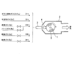
- reference numeral 1 denotes a target member, which is accommodated in a chamber 2, and both ends thereof are rotatably supported by a glass lathe or the like.
- the target member 1 is formed by a rod-shaped member that is removed in a later step or becomes a core of an optical fiber preform or a rod-shaped member that becomes a part of a core and a clad around the core.
- the chamber 2 rectifies the flame and the glass particulate flow and protects the glass particulate deposition layer.
- One of the side walls of the chamber 2 (lower right side in FIG.
- a combustion burner 3 for synthesizing glass particles is disposed in the opening 2 a of the chamber 2.
- the combustion burner 3 traverses and circulates a section (X1X2X3X4X1) in the figure by traverse means (not shown) provided outside.
- the combustion burner 3 (for example, FIG. 3) having a multi-tube structure will be described in detail.
- the method for manufacturing an optical fiber preform according to the present invention includes the configuration illustrated in FIG.
- the configuration is not limited to a configuration in which inert gas ejection nozzles and the like are arranged concentrically.
- Each nozzle (a glass raw material gas injection nozzle, an inert gas injection nozzle, etc.) constituting the combustion burner 3 having a multi-tube structure is arranged so as to be “near” or “close” to each other at the wall thickness level of the pipe. .
- the multiple tube structure as shown in FIG.
- At least two adjacent combustion gas port glass raw material gas injection nozzles and inert gas injection nozzles are independent in the “near” glass raw material gas injection nozzle.
- a structure to be arranged at least one of the combustion gas ports may include an auxiliary combustion gas ejection nozzle disposed so as to “near” the glass source gas ejection nozzle.
- “near” or “cuckling” means being disposed within a distance that can generate red heat at the nozzle tip of the combustion burner in the “fired state”.
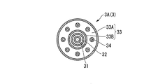
- FIG. 3 is a view of an example of a nozzle portion of the combustion burner 3 used in such a manufacturing apparatus as viewed from the front end side.
- the combustion burner 3A (3) includes a glass raw material gas injection nozzle 31 disposed in the center, an inert gas injection nozzle 32 disposed outside the glass raw material gas injection nozzle 31, and an outer side of the inert gas injection nozzle 32. At least two adjacent combustion gas ports 33 arranged concentrically.
- the combustion gas port 33 has at least one combustion gas port 33 ⁇ / b> A including a plurality of small-diameter auxiliary combustion gas ejection nozzles 34 arranged concentrically with respect to the glass raw material gas ejection nozzle 31.
- the combustion gas port 33 also has at least one combustion gas port 33 ⁇ / b> B that does not include the auxiliary combustion gas ejection nozzle 34.
- combustion gas here, H 2 gas
- auxiliary combustion gas O 2 gas
- glass raw material gas are supplied from various gas supply sources (not shown) through various gas supply pipes.
- SiCl 4 a gas supply source gas
- an inert gas such as Ar gas
- N 2 gas a purge gas
- glass source gas SiCl 4
- An inert gas (such as Ar gas) is supplied to the inert gas ejection nozzle 32.
- the inert gas used here is sometimes called a seal gas.
- the inert gas ejection nozzle 32 is provided in order to prevent the reaction product of the raw material from accumulating at the tip of the glass raw material gas ejection nozzle 31, but is not essential in the present invention.
- each gas described above is appropriately introduced into the combustion burner 3.
- combustion gas (H 2 gas) or purge gas (N 2 gas) is supplied to the combustion gas port 33A.
- combustion gas (H 2 gas) is supplied to the combustion gas port 33B.
- a combustion gas pipe and a purge gas pipe are connected in parallel to the combustion gas supply pipe connected to the combustion gas port 33A.
- Combustion gas and purge gas are switched by opening and closing valves disposed in the combustion gas pipe and purge gas pipe, respectively, and the flow rate thereof is controlled.
- the piping structure is not limited to the above, and it is sufficient if it has a function of switching between combustion gas and purge gas.
- a structure using a three-way valve or the like may be employed.
- An auxiliary combustion gas (O 2 gas) is supplied to the auxiliary combustion gas ejection nozzle 34.
- the apparatus for manufacturing an optical fiber preform shifts the combustion gas from a deposition mode in which glass particulates are deposited around the target member to a non-deposition mode in which glass particulates are not deposited.
- the combustion gas from the port 33B is used to maintain the flame of the combustion burner 3, and the flow rate of the auxiliary combustion gas injected from the auxiliary combustion gas injection nozzle 34 of the combustion gas port 33A is maintained to be higher than the flow rate at which the nozzle tip does not become red hot.
- a gas switching mechanism for switching the gas ejected from the combustion gas port 33A from the combustion gas to the purge gas is provided.
- the gas switching mechanism maintains or decreases the flow rate of the auxiliary combustion gas, stops the injection of the auxiliary combustion gas, or switches the gas injected from the auxiliary combustion gas injection nozzle 34 from the auxiliary combustion gas to the purge gas. it can.
- This gas switching mechanism also functions to switch the injection gas in the auxiliary combustion gas injection nozzle and each combustion gas port when shifting from the non-deposition mode to the deposition mode.
- a glass particulate deposit can be obtained by traversing a plurality of times from one direction in the axial direction of the rotating target member to form a glass particulate deposition layer 5 around the target member 1. It can. Specifically, first, while rotating the target member 1 and burning the combustion burner 3 facing the outer periphery of the target member 1, the point X2 from the point X1 (deposition start position) shown in FIG. Traverse to (deposition end position). In the section of X1 ⁇ X2 corresponding to the deposition process (deposition mode) of the combustion burner 3, by operating the valve 6 and the valve 7 attached to the burner, the combustion gas, auxiliary combustion gas, glass raw material gas, and inert gas are generated. Then, glass fine particles are generated in the flame 4 by the flame hydrolysis reaction. Glass particulates generated in the flame 4 adhere to the outer periphery of the target member 1 and are gradually deposited to form a glass particulate deposition layer 5.
- the combustion burner 3 When the combustion burner 3 reaches the deposition end position X2 and the deposition process is completed, the combustion burner 3 is driven by the external traversing means to move through a section from the point X2 to the deposition start position X1 via X3 and X4. Moving. In this section, the combustion burner 3 enters the return process (non-deposition mode). The combustion burner 3 moves backward from the point X2. That is, the combustion burner 3 retracts from the target member 1 and the opening 2a of the chamber 2 and falls to the position X3. Thereafter, the combustion burner 3 moves to the left in FIG. 1, that is, from the point X3 to the point X4 so as not to come into contact with other burners. When the combustion burner 3 reaches the point X4 at the left end in FIG. 1, it rises in the direction of X1, enters the chamber 5, and moves again from X1 to X2.
- the present invention is not limited to the above-described “circulation method”, and may be a “reciprocation method”.
- the “reciprocating method” traverse in the section of X1 ⁇ X2 as in the above circulation method, and after reaching X2, use the combustion burner 3 as a starter to traverse toward X1 and burn after reaching X1.
- the burner 3 can be changed to a flame corresponding to the deposition mode and the operation of X1 ⁇ X2 is performed again.
- This configuration is particularly effective when two or more burners constitute one unit and the burner is driven in units. That is, according to this configuration, the burner in the unit can be shifted to the non-deposition mode at individual timing.
- a method of repeatedly performing such an operation is defined as a “reciprocating method” in the present specification.
- the glass particulate deposit formed of the porous body formed as described above is taken out from the chamber 2 and then heat-treated in a high-temperature heating furnace, so that the glass particulate deposit becomes a transparent glass, and the target optical fiber is obtained. A base material is obtained.
- the method of manufacturing the optical fiber preform of the present embodiment starts from the deposition mode (X1 ⁇ X2 interval) in which glass particles are deposited around the target member in the circulation of the traverse of the combustion burner 3 as described above.
- the combustion gas from the combustion gas port 33B is used to maintain the seed flame of the combustion burner 3 and the combustion
- the gas ejected from the combustion gas port A is purged from the combustion gas in a state where the flow rate of the auxiliary combustion gas ejected from the auxiliary combustion gas ejection nozzle of the gas port 33A is maintained at a flow rate higher than that at which the nozzle tip is not red-hot.
- the process ⁇ to switch to is provided. After switching from the combustion gas to the purge gas, the flow rate of the auxiliary combustion gas is maintained and decreased, or the injection of the auxiliary combustion gas is stopped, or the gas injected from the auxiliary combustion gas injection nozzle 34 is purged from the auxiliary combustion gas. You may switch to.
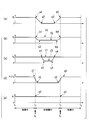
- FIGS. 4A to 4E are common time axes.
- the first deposition mode (described as “depositing” in the figure)
- the non-deposition mode (described as “not depositing” in the figure)
- time T3 and time T4 the second deposition mode (described as “depositing” in the figure) is shown.
- time T2 corresponds to the position X2 in FIG. 1
- time T3 corresponds to the position X1 in FIG.
- the vertical axis in each graph shown in FIG. 4 indicates the flow rate of the combustion gas (H 2 gas) supplied to the combustion gas port 33A in the case of (a), and the combustion gas port 33B in the case of (b).
- the flow rate of the supplied combustion gas (H 2 gas) in the case of (c), the flow rate of the auxiliary combustion gas (O 2 gas) supplied to the auxiliary combustion gas jet nozzle 34, in the case of (d), the glass raw material gas jet
- the flow rate of the glass raw material gas (SiCl 4 ) supplied to the nozzle 31 is shown, and in the case of (e), the flow rate of the inert gas (Ar gas or the like) supplied to the inert gas ejection nozzle 32 is shown.
- reference numeral a1 indicates that the gas flow is interrupted at time T2
- reference numeral a2 indicates that the gas flow rate has reached zero
- reference numeral a3 indicates that the gas flow has been restored
- a4 indicates that the gas flow has been recovered at time T3.
- the flow rate of the combustion gas supplied to the combustion gas port 33B during non-deposition is controlled to be a level Y2 lower than the level Y1 during deposition (b1b2b3b4). Although this control is not essential, it is preferable because the thermal power is suppressed as the flow rate of the combustion gas during non-deposition is reduced. In particular, the change of “a1a2” in FIG.
- the point to be noted in the flow control of the auxiliary combustion gas is that the timing at which the flow rate is reduced from “c1”, the supply of the auxiliary combustion gas is stopped, or the switching from the auxiliary combustion gas to the purge gas is started is the timing “a2”. It is a point set afterwards. That is, it is important that the purge gas is flowing to the port 33A at the time when the flow rate of the auxiliary combustion gas is controlled as described above. It does not matter in particular whether the flow rate of the port 33B is Y1 or Y2. That is, as shown in FIG.
- the flow rate of the auxiliary combustion gas supplied to the auxiliary combustion gas ejection nozzle 34 during non-deposition is controlled to be equal to or lower than the level Z1 during deposition. Control is performed to achieve level Z2. Further, although not shown, the supply of the auxiliary combustion gas may be completely stopped, or the auxiliary combustion gas may be switched to the purge gas.
- the flow rate of the glass raw material gas supplied to the glass raw material gas injection nozzle 31 decreases (d1 ⁇ d2) so as to straddle time T2, and increases so as to straddle time T3 (d3). ⁇ d4).
- the flow rate of the glass source gas is half of the flow rate during deposition at times T2 and T3.
- the increase / decrease profile shown in FIG. 4 shows an example in which the timing for switching between the deposition mode and the non-deposition mode and the timing for switching the combustion gas are intentionally “shifted”. When these two timings are the same, two different types of gas are mixed instantaneously, and an unstable situation that is three-dimensionally disturbed tends to occur.
- the combustion gas is switched at a constant time interval.
- the stability of the state is easily secured, and as a result, the controllability is improved. That is, since the high temperature portion of the combustion gas is stable and can be maintained at a position away from the nozzle tip, the nozzle tip does not become hot either. That is, it is more preferable because the nozzle tip does not have an opportunity to become high temperature.
- the flow rate of the inert gas supplied to the inert gas ejection nozzle 32 is a constant amount even during the deposition (non-deposition) (e1, e2). Just keep it.
- the tip of the auxiliary combustion gas nozzle becomes red hot in the combustion gas port 33A when the flow rates of the combustion gas and the auxiliary combustion gas are too low.
- the combustion gas and the auxiliary combustion gas burn near the nozzle tip, so that the nozzle tip becomes high temperature. Therefore, in order to avoid red heat at the tip of the auxiliary combustion gas nozzle, the flow rate of the combustion gas or auxiliary combustion gas may be increased.
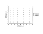
- FIG. 5 is a diagram showing the result of visual confirmation of the red heat state at the tip of the auxiliary combustion gas nozzle at that time.
- FIG. 5 shows that when the flow rate of the O 2 gas is constant, a red hot state occurs when the flow rate of the H 2 gas decreases.
- the purge gas for the auxiliary combustion gas may be a gas having a low auxiliary combustion property
- the purge gas for the combustion gas may be a gas having a low combustion property.
- inert gas or nitrogen gas is preferable from the viewpoint of ease of handling.
- the auxiliary combustion gas is flowed through the auxiliary gas nozzle at a flow rate of 0 to 8 m / sec.
- redness of the nozzle was not confirmed.
- nitrogen was flowed through the auxiliary combustion gas nozzle while changing the flow rate from 0 to 8 m / sec, red hotness of the nozzle was not confirmed.
- the state is shifted to the state (2), and then the flow rate of the auxiliary combustion gas is decreased, so that the nozzle tip does not have an opportunity to reach a high temperature.
- the tip of the nozzle does not become hot either by the state of (1), the decrease of the combustion gas flow rate in (2), or the subsequent decrease of the auxiliary combustion gas flow rate.
- the flow rate of the auxiliary combustion gas ejected from the auxiliary combustion gas ejection nozzle of the combustion gas port 33A is maintained at a flow rate higher than that at which the nozzle tip does not red heat. Therefore, the nozzle tip does not become red hot even if the flow velocity of the combustion gas is slowed to some extent. In the state where the gas ejected from the combustion gas port A is switched from the combustion gas to the purge gas, combustion does not occur, and the nozzle tip does not become high temperature.
- the supply of the auxiliary combustion gas is stopped, or the gas ejected from the auxiliary combustion gas ejection nozzle is switched from the auxiliary combustion gas to the purge gas, so that the nozzle tip does not have an opportunity to reach a high temperature. Even if the flow rate of the combustion gas is lowered and then the flow rate of the auxiliary combustion gas is lowered, the nozzle tip does not reach a high temperature.
- step ⁇ since the seed of the combustion burner 3 is maintained at the combustion gas port 33B, it is possible to ignite surely and quickly when shifting from the non-deposition mode to the deposition mode later (step ⁇ ). Therefore, it is possible to suppress a decrease in deposition efficiency.
- deterioration due to red heat at the nozzle tip can be suppressed without lowering the deposition efficiency. In particular, when the transition from the deposition mode to the non-deposition mode (seed fire state) is repeated frequently. The deterioration of the nozzle tip can be effectively suppressed.
- the combustion gas is supplied to the combustion gas port 33B and ignited, and then the auxiliary combustion gas at the combustion gas port 33A.
- the auxiliary combustion gas is allowed to flow from the ejection nozzle 34 at a flow rate higher than that at which the tip of the nozzle is not red-hot, and supply of the combustion gas is started to start combustion (step ⁇ ). That is, the combustion gas that has flowed out of the combustion gas port 33B is ignited while the purge gas is flowing through the combustion gas port 33A. More specifically, the combustion gas is ignited while flowing the purge gas to the combustion gas port 33A and the combustion gas to the combustion gas port 33B. At this time, the auxiliary combustion gas is increased to a predetermined flow rate or higher, and then the purge gas of the combustion gas port 33A is switched to the combustion gas.
- two combustion gas ports 33 are arranged adjacent to each other.
- the two combustion gas ports 33 are adjacent to each other, if the seed gas is maintained with the combustion gas from any one of the combustion ports, the combustion gas starts to flow to the other adjacent combustion gas ports 33. It can reliably ignite spontaneously (ignition). That is, in order to reduce the possibility of ignition failure, it is preferable that the combustion gas ports 33 are adjacent to each other.
- the combustion gas is brought into a ignited state at the combustion gas port 33B on the center side, and the auxiliary combustion gas (O 2 gas) is supplied to the auxiliary combustion gas nozzle of the combustion gas port 33A at 6 [m /
- the inert gas (N 2 gas) was allowed to flow through the combustion gas port 33A, switching from the inert gas to the combustion gas (H 2 gas) was performed, and ignition occurred without any problem.
- the nozzle when shifting from the deposition mode to the non-deposition mode (extinguishing), the nozzle does not become hot and deforms even if the burner thermal power is reduced. The deterioration of the burner due to the red heat of the burner is prevented, and as a result, the life of the burner can be extended.
- an inert gas that inhibits the combustion reaction can be excluded, so that a decrease in the deposition rate can be prevented.
- the flame is maintained by the seed fire, when shifting from the non-deposition mode to the deposition mode (ignition), a separate means for reigniting is unnecessary, and the ignition can be performed reliably and quickly. Therefore, it is possible to prevent a decrease in deposition efficiency.
- the burner structure as described above does not require a seal layer around the oxygen nozzle, and can be obtained by adding only the function of switching to the purge gas for the gas system, so that the structure of the burner and the gas system is not complicated. Therefore, it is possible to prevent the occurrence of an initial trouble from the start of use due to a decrease in burner quality (accuracy) or the like.
- the simple structure does not reduce the deposition efficiency. As described above, in the present embodiment, deterioration due to red heat at the nozzle tip can be suppressed without lowering the deposition efficiency. In particular, when the transition to the deposition mode non-deposition mode (seed fire state) deposition mode is repeated frequently. The deterioration of the nozzle tip can be effectively suppressed.
- the combustion burner 3 having the above-described structure; and the combustion gas from the combustion gas port 33B when the transition from the deposition mode to the non-deposition mode is performed.
- the combustion gas is maintained in a state in which the flame of the combustion burner 3 is maintained and the flow rate of the auxiliary combustion gas injected from the auxiliary combustion gas injection nozzle 34 of the combustion gas port 33A is maintained at a flow rate higher than that at which the nozzle tip is not red hot.
- a gas switching mechanism for switching the gas ejected from the port A from the combustion gas to the purge gas is provided.
- the gas switching mechanism can stop the ejection of the auxiliary combustion gas or switch the gas ejected from the auxiliary combustion gas ejection nozzle 34 to the purge gas. Therefore, according to such an optical fiber preform manufacturing apparatus, the deterioration of the nozzle tip due to red heat can be suppressed with a simple configuration, and the life of the combustion burner 3 can be extended.
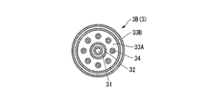
- the combustion burner 3A having the nozzle structure in which the combustion gas port 33B is disposed on the inner side of the combustion gas port 33A has been described as an example.
- the present invention is not limited to this. Absent.
- the structure where the combustion gas port 33A is arranged inside the combustion gas port 33B may be used.
- the combustion burner 3 may include two or more combustion gas ports 33A and / or combustion gas ports 33B.
- the combustion burner 3 may include two or more combustion gas ports 33A and / or combustion gas ports 33B.
- it is good also as a structure (33Aa, 33Ab) provided with two combustion gas ports 33A like the combustion burner 3C (3) shown in FIG.
- combustion burner 3 for synthesizing glass fine particles has been described, but the present invention is not limited to this.
- a plurality of combustion burners 3a, 3b, 3c (3) for synthesizing glass particles may be arranged.
- the chamber 2 having the opening 2a for arranging and traversing the combustion burner 3 has been described.
- the structure of the chamber 2 is not limited to this.
- a chamber having a slit (gap) through which the combustion burner 3 can enter and exit may be used.
- Example 1 A combustion burner having a nozzle structure as shown in FIG. 3 is used to traverse the combustion burner multiple times from one direction in the axial direction of the rotating target member to form a glass particulate deposition layer around the target member. Thus, a glass fine particle deposit was obtained. An optical fiber preform was produced from this glass particulate deposit.
- the state of the nozzle tip was visually observed. As a result, no red heat was observed in any of the steps, and no deformation of the nozzle was observed.
- the flow rate of the combustion gas (H 2 gas) at the time of seeding was 10 slm.
- Example 2 100 optical fiber preforms were produced in the same manner as in Example 1 except that the amount of combustion gas (H 2 gas) at the time of seeding was 7 slm. As a result, the fire was extinguished during the production of the third base material. After that, when a supporting gas (O 2 gas) was allowed to flow for 4 slm during the seed fire, the seed fire did not disappear even when 100 optical fiber preforms were manufactured.
- H 2 gas combustion gas
- Example 3 An optical fiber preform was manufactured in the same manner as in Example 1 except that the extinguishing was performed by stopping the combustion gas in the combustion gas port B. As a result of visually observing the state of the nozzle tip during the production, no red heat of the nozzle was observed.
- Example 4 When shifting from the non-deposition mode to the deposition mode, the combustion gas is supplied to the combustion gas port B and ignited, and then the auxiliary combustion gas is allowed to flow in the combustion gas port A at a flow rate higher than that at which the nozzle tip does not red heat.
- an optical fiber preform was manufactured in the same manner as in Example 1 except that ignition was started by the method of starting the supply of the combustion gas and starting combustion. As a result of visually observing the state of the nozzle tip during the production, no red heat of the nozzle was observed.
- Example 1 the nozzle tip is obtained by using the method according to the above embodiment when shifting from the deposition mode to the non-deposition mode or when shifting from the non-deposition mode to the deposition mode. It was confirmed that degradation of the nozzle tip due to red heat could be suppressed without giving an opportunity to become high temperature.
- Example 3 and Comparative Example 2 by stopping the combustion gas in the combustion gas port B during extinguishing, deterioration due to red heat at the nozzle tip can be suppressed and fire extinguishing can be performed quickly and naturally. confirmed.
- Example 4 if the ignition is maintained in one combustion gas port, the combustion gas starts to flow to the other adjacent combustion gas port, thereby deteriorating the nozzle tip portion due to red heat. It was confirmed that it can be ignited spontaneously (ignition) while being suppressed.
- the present invention is widely applicable to an optical fiber preform manufacturing apparatus and manufacturing method based on a so-called external method.
- the present invention is particularly effective in the deposition method in which the seed fire state is frequently repeated, but is also effective in the production of a porous body that repeats general ignition and extinguishing.
Landscapes
- Chemical & Material Sciences (AREA)
- Engineering & Computer Science (AREA)
- Life Sciences & Earth Sciences (AREA)
- General Life Sciences & Earth Sciences (AREA)
- Chemical Kinetics & Catalysis (AREA)
- General Chemical & Material Sciences (AREA)
- Geochemistry & Mineralogy (AREA)
- Materials Engineering (AREA)
- Organic Chemistry (AREA)
- Manufacturing & Machinery (AREA)
- Manufacture, Treatment Of Glass Fibers (AREA)
- Glass Melting And Manufacturing (AREA)
Abstract
ガラス原料ガス噴出ノズル、並びにその近傍に配された複数の助燃ガス噴出ノズルを有する燃焼ガスポートA及び前記助燃ガス噴出ノズルを含まない燃焼ガスポートBを有する燃焼バーナを用いた光ファイバ母材の製造方法であって、ターゲット部材の周囲へのガラス微粒子堆積を行う積モードから、前記堆積を行わない非堆積モードに移行する際に、前記燃焼ガスポートBからの燃焼ガスで種火を維持し、前記助燃ガス噴出ノズルからの助燃ガスの流速を一定以上に維持した状態で、前記燃焼ガスポートAから噴出するガスを前記燃焼ガスからパージガスに切り替える工程α;及び前記非堆積モードから前記堆積モードに移行する際に、前記燃焼ガスポートBからの燃焼ガスで前記燃焼バーナの種火を維持し、前記助燃ガス噴出ノズルからの助燃ガスの流速を一定以上に維持した状態で、前記燃焼ガスポートAから噴出するガスを前記パージガスから燃焼ガスに切り替える工程β;のうちの少なくとも一方を備える。
Description
本発明は、いわゆる外付け法による光ファイバ母材の製造装置及び製造方法に関する。
本願は、2010年5月27日に、日本に出願された特願2010-121902号に基づき優先権を主張し、その内容をここに援用する。
本願は、2010年5月27日に、日本に出願された特願2010-121902号に基づき優先権を主張し、その内容をここに援用する。
一般に外付け法と呼ばれる製造方法に基づく光ファイバ母材の製造装置では、棒状の夕-ゲット部材の両端をガラス旋盤などで保持して回転させ、ターゲット部材の周囲に、ガラス微粒子生成用燃焼バーナの火炎中で生成されたガラス微粒子を堆積させる。このターゲット部材は後に除去されたり、あるいは後に光ファイバとされたときにコア部となる石英系のガラス棒であったりする。
ガラス原料ガスを燃焼ガス及び助燃ガスとともにバーナの火炎中に導入することにより、火炎中で火炎加水分解反応等を生じさせてSiO2等のガラス微粒子を生成する。このガラス微粒子を前記のように回転するターゲット部材の周囲に堆積する。
ガラス微粒子生成用燃焼バーナをターゲット部材の軸方向にトラバースさせながら、この堆積工程を行うことによりターゲット部材の周囲にガラス微粒子堆積層を形成し、その堆積層が所定の重量となったとき堆積工程を終了する。
こうして形成されたターゲット部材とガラス微粒子堆積層との複合体であるガラス微粒子堆積体が、後に、高温の炉の中で加熱処理され、ガラス微粒子堆積層の部分が焼結されて透明ガラス化され、光ファイバ母材が得られる。
ガラス微粒子生成用燃焼バーナをターゲット部材の軸方向にトラバースさせながら、この堆積工程を行うことによりターゲット部材の周囲にガラス微粒子堆積層を形成し、その堆積層が所定の重量となったとき堆積工程を終了する。
こうして形成されたターゲット部材とガラス微粒子堆積層との複合体であるガラス微粒子堆積体が、後に、高温の炉の中で加熱処理され、ガラス微粒子堆積層の部分が焼結されて透明ガラス化され、光ファイバ母材が得られる。
この光ファイバ母材の製造装置において、複数のガラス微粒子生成用燃焼バーナを順次一方向にトラバースさせてガラス微粒子堆積を行うことがある。この場合、一つのバーナは、堆積開始点から終了点に至る期間のみガラス微粒子生成・堆積を行い、その後は他の、トラバースしながらガラス微粒子堆積しているバーナの障害とならないようにトラバース行路から外れた行路を通って堆積開始点にまで戻る。この戻りの期間ではバーナの火炎は極力小さくする必要があるので、従来では燃焼ガス及び助燃ガスの流量をできるだけ下げるか、あるいは、燃焼ガスの流量を極力下げるとともに助燃ガスの弁を閉じている。
しかしながら、前記のように堆積終了点から堆積開始点までの戻りの期間において燃焼ガス及び助燃ガスの流量をできるだけ下げる場合には、ガラス微粒子生成用燃焼バーナのノズル近辺で炎が燃焼し、ノズル先端が赤熱してしまい、バーナの寿命が極端に短くなるという問題がある。
このような問題に対し、例えば、戻りの期間において酸素の導入を停止する方法(例えば、特許文献1参照)や、戻りの期間において酸素ノズルにパージガスを流す方法(例えば、特許文献2参照)などが提案されている。
また、酸素ノズル先端の劣化への対策として、例えば、水素に不活性ガスや窒素を混合したガスを用いること方法(例えば、特許文献3参照)や、ノズルの厚みを1mm以下に薄くし、ガスの流速を高くすること方法(例えば、特許文献4参照)、酸素ガス用ノズルの周囲にシール層を設けること方法(例えば、特許文献5参照)などが提案されている。
なお、上述した文献において、酸素は「助燃ガス」に、水素は「燃焼ガス」に、不活性ガスや窒素は「パージガス」に、それぞれ相当する。
また、酸素ノズル先端の劣化への対策として、例えば、水素に不活性ガスや窒素を混合したガスを用いること方法(例えば、特許文献3参照)や、ノズルの厚みを1mm以下に薄くし、ガスの流速を高くすること方法(例えば、特許文献4参照)、酸素ガス用ノズルの周囲にシール層を設けること方法(例えば、特許文献5参照)などが提案されている。
なお、上述した文献において、酸素は「助燃ガス」に、水素は「燃焼ガス」に、不活性ガスや窒素は「パージガス」に、それぞれ相当する。
しかしながら、前記の特許文献1、特許文献2に記載の方法においても、ガスの流量が変化、つまりガスの流速が低下する瞬間においては、ノズルが一時的に高温になり、これを繰り返すことにより、ノズルが変形することがある。
また、特許文献3に記載の方法では、製造条件によっては少なからず堆積効率に影響を及ぼし好ましくない場合がある。
また、特許文献3に記載の方法では、製造条件によっては少なからず堆積効率に影響を及ぼし好ましくない場合がある。
特許文献4に記載の方法では、点火、消火、種火などの状況においてがガスの流速が減るため、ノズルが赤熱してしまう。また、ノズルの厚みをlmm以下にすると前記赤熱による変形が著しくなり、結局ノズルの寿命が短くなってしまう。
さらに、特許文献5に記載の方法では、ノズルの変形を避けられるが、シール層を設けることでバーナが大型化、複雑化して好ましくない。また、バーナの製作精度が落ちたり、バーナが大きくなりすぎて堆積効率が低下したりする。
さらに、特許文献5に記載の方法では、ノズルの変形を避けられるが、シール層を設けることでバーナが大型化、複雑化して好ましくない。また、バーナの製作精度が落ちたり、バーナが大きくなりすぎて堆積効率が低下したりする。
本発明は、上記のような実情に鑑みてなされたものであり、ガラス微粒子生成用燃焼バーナを用いた光ファイバ母材の製造方法において、堆積効率を低下させることなくノズル先端部の赤熱による劣化を抑制できる、とくに堆積モードと非堆積モード(種火状態)との間の移行を高い頻度で繰り返す場合により効果的にノズル先端部の劣化を抑制できる、光ファイバ母材の製造方法の提供を第一の目的とする。
また、本発明は、ガラス微粒子生成用燃焼バーナを備えた光ファイバ母材の製造装置において、シンプルな構成であり、ノズル先端部の赤熱による劣化を抑制し、堆積モードと非堆積モード(種火状態)との間の移行を高い頻度で繰り返す場合でも、燃焼バーナの長寿命化を図ることが可能な、光ファイバ母材の製造装置の提供を第二の目的とする。
また、本発明は、ガラス微粒子生成用燃焼バーナを備えた光ファイバ母材の製造装置において、シンプルな構成であり、ノズル先端部の赤熱による劣化を抑制し、堆積モードと非堆積モード(種火状態)との間の移行を高い頻度で繰り返す場合でも、燃焼バーナの長寿命化を図ることが可能な、光ファイバ母材の製造装置の提供を第二の目的とする。
本発明の第1の態様に係る光ファイバ母材の製造方法は、ガラス原料ガス噴出ノズル、及び前記ガラス原料ガス噴出ノズルの近傍に配された少なくとも2つ以上の互いに隣接する燃焼ガスポートを有し、前記燃焼ガスポートが、前記ガラス原料ガス噴出ノズルに対して寄り添うように配置された複数の小口径の助燃ガス噴出ノズルを有する少なくとも1つの燃焼ガスポートAと、前記助燃ガス噴出ノズルを含まない少なくとも1つの燃焼ガスポートBと、を有する燃焼バーナを用いて、前記ガラス原料ガス噴出ノズルからのガラス原料ガス、前記各燃焼ガスポートからの燃焼ガス及び前記助燃ガス噴出ノズルからの助燃ガスからなる混合ガスを燃焼することによりターゲット部材の周囲にガラス微粒子を堆積させる光ファイバ母材の製造方法であって、前記ターゲット部材の周囲に前記ガラス微粒子を堆積させる堆積モードから、前記ターゲット部材の周囲にガラス微粒子を堆積させない非堆積モードに移行する際に、前記燃焼ガスポートBからの燃焼ガスで前記燃焼バーナの種火を維持し、前記燃焼ガスポートAの前記助燃ガス噴出ノズルから噴出される助燃ガスの流速を前記ノズル先端が赤熱しない程度の流速以上に維持した状態で、前記燃焼ガスポートAから噴出するガスを前記燃焼ガスからパージガスに切り替える工程α;及び前記ターゲット部材の周囲にガラス微粒子を堆積させない非堆積モードから、前記ターゲット部材の周囲に前記ガラス微粒子を堆積させる堆積モードに移行する際に、前記燃焼ガスポートBからの燃焼ガスで前記燃焼バーナの種火を維持し、前記燃焼ガスポートAの前記助燃ガス噴出ノズルから噴出される助燃ガスの流速を前記ノズル先端が赤熱しない程度の流速以上に維持した状態で、前記燃焼ガスポートAから噴出するガスを前記パージガスから燃焼ガスに切り替える工程β;のうちの少なくとも一方を備える。
上記光ファイバ母材の製造方法は、前記工程αを備え、前記燃焼ガスからパージガスへの切替えを行った後に、前記助燃ガスの流量を維持し、減少させ、若しくは前記助燃ガス噴出ノズルからの助燃ガスの噴出を停止し、あるいは前記助燃ガス噴出ノズルから噴出するガスを前記助燃ガスからパージガスに切り替えてもよい。
上記光ファイバ母材の製造方法は、前記工程αを備え、前記燃焼ガスからパージガスへの切替えを行った後に、前記助燃ガスの流量を維持し、減少させ、若しくは前記助燃ガス噴出ノズルからの助燃ガスの噴出を停止し、あるいは前記助燃ガス噴出ノズルから噴出するガスを前記助燃ガスからパージガスに切り替えてもよい。
上記光ファイバ母材の製造方法は、前記工程βを備え、前記工程βに先だって、前記助燃ガスの流量を維持し、増加させ、若しくは前記助燃ガス噴出ノズルからの助燃ガスの噴出を開始し、あるいは前記助燃ガス噴出ノズルから噴出するガスを前記パージガスから助燃ガスに切り替えてもよい。
上記光ファイバ母材の製造方法は、前記工程αおよび前記工程βを備えてもよい。
上記光ファイバ母材の製造方法は、前記工程αおよび前記工程βを備えてもよい。
本発明の第2の態様に係る光ファイバ母材の製造装置は、ガラス原料ガス噴出ノズル、及び前記ガラス原料ガス噴出ノズルの近傍に、少なくとも2つ以上の互いに隣接する燃焼ガスポートを有し、前記燃焼ガスポートが、前記ガラス原料ガス噴出ノズルに対して寄り添うように配置された複数の小口径の助燃ガス噴出ノズルを有する少なくとも1つの燃焼ガスポートAと、前記助燃ガス噴出ノズルを含まない少なくとも1つの燃焼ガスポートBと、を有する燃焼バーナを用いて、前記ガラス原料ガス噴出ノズルからのガラス原料ガス、前記各燃焼ガスポートからの燃焼ガス及び前記助燃ガス噴出ノズルからの助燃ガスからなる混合ガスを燃焼することによりガラス微粒子を堆積させる燃焼バーナと;前記ターゲット部材の周囲に前記ガラス微粒子を堆積させる堆積モード及び前記ガラス微粒子を堆積させない非堆積モードの2つの間を移行する際に、前記燃焼ガスポートBからの燃焼ガスで前記燃焼バーナの種火を維持し、前記燃焼ガスポートAの前記助燃ガス噴出ノズルから噴出される助燃ガスの流速を前記ノズル先端が赤熱しない程度の流速以上に維持した状態で、前記燃焼ガスポートAから噴出するガスを前記燃焼ガスからパージガスに切り替える又は前記燃焼ガスポートAから噴出するガスをパージガスから前記燃焼ガスに切り替えるガス切替機構と;を少なくとも備える。
前記ガラス原料ガス噴出ノズルは前記燃焼バーナの中心に配され、前記燃焼ガスポートA及び前記燃焼ガスポートBは、前記ガラス原料ガス噴出ノズルの外側に、該ガラス原料ガス噴出ノズルに対して同心円状に配置されていてもよい。
前記ガラス原料ガス噴出ノズルは前記燃焼バーナの中心に配され、前記燃焼ガスポートA及び前記燃焼ガスポートBは、前記ガラス原料ガス噴出ノズルの外側に、該ガラス原料ガス噴出ノズルに対して同心円状に配置されていてもよい。
本発明の第1の態様に係る光ファイバ母材の製造方法は、ターゲット部材の周囲にガラス微粒子を堆積させる堆積モードから、ガラス微粒子を堆積させない非堆積モードに移行する際に、前記燃焼ガスポートBからの燃焼ガスで燃焼バーナの種火を維持し、前記燃焼ガスポートAの前記助燃ガス噴出ノズルから噴出される助燃ガスの流速を前記ノズル先端が赤熱しない程度の流速以上に維持した状態で、前記燃焼ガスポートAから噴出するガスを燃焼ガスからパージガスに切り替える工程α;及び前記ターゲット部材の周囲にガラス微粒子を堆積させない非堆積モードから、前記ターゲット部材の周囲にガラス微粒子を堆積させる堆積モードに移行する際に、前記燃焼ガスポートBからの燃焼バーナの燃焼ガスで種火を維持し、前記燃焼ガスポートAの前記助燃ガス噴出ノズルから噴出される助燃ガスを前記ノズル先端が赤熱しない程度の流速以上に維持した状態で、前記燃焼ガスポートAから噴出するガスをパージガスから燃焼ガスに切り替える工程β;のうちの少なくとも一方を備えている。
上記光ファイバ母材の製造方法が工程αを備える場合、堆積モードから非堆積モードへ移行するに際し、前記燃焼ガスポートAの助燃ガス噴出ノズルから噴出される助燃ガスを前記ノズル先端が赤熱しない程度の流速以上に維持することで、燃焼ガスポートAからの燃焼ガスの流速がある程度遅くなってもノズル先端が赤熱しない。前記燃焼ガスポートAから噴出するガスを燃焼ガスからパージガスに切り替えた状態では、燃焼は起きないため、ノズル先端も高温にならない。つまり、ノズル先端が高温になるのを防ぐことができる。前記燃焼ガスポートAから噴出するガスを燃焼ガスからパージガスに切り替えた後、助燃ガスの流量を維持し、減少させ、若しくは助燃ガス噴出ノズルからの助燃ガスの噴出を停止し、あるいは助燃ガス噴出ノズルから噴出するガスを助燃ガスからパージガスに切り替えれば、ノズル先端が高温になるのをより確実に防ぐことができる。
また、燃焼ガスポートBで燃焼バーナの種火を維持しているので、後に非堆積モードから堆積モードに移行する際に、確実にかつ迅速に着火できる。したがって、堆積効率の低下を抑制することができる。
以上説明の通り、本発明の上記態様では、堆積効率を低下させることなくノズル先端部の赤熱による劣化を抑制できる、とくに堆積モードから非堆積モード(種火状態)への移行を高い頻度で繰り返す場合により効果的にノズル先端部の劣化を抑制できる、光ファイバ母材の製造方法を提供することができる。
なお、上述した工程αの後に、「消火状態」を設けてもよい。すなわち、工程αの「種火状態」から「消火状態」へ移行させてもよい。
上記光ファイバ母材の製造方法が工程αを備える場合、堆積モードから非堆積モードへ移行するに際し、前記燃焼ガスポートAの助燃ガス噴出ノズルから噴出される助燃ガスを前記ノズル先端が赤熱しない程度の流速以上に維持することで、燃焼ガスポートAからの燃焼ガスの流速がある程度遅くなってもノズル先端が赤熱しない。前記燃焼ガスポートAから噴出するガスを燃焼ガスからパージガスに切り替えた状態では、燃焼は起きないため、ノズル先端も高温にならない。つまり、ノズル先端が高温になるのを防ぐことができる。前記燃焼ガスポートAから噴出するガスを燃焼ガスからパージガスに切り替えた後、助燃ガスの流量を維持し、減少させ、若しくは助燃ガス噴出ノズルからの助燃ガスの噴出を停止し、あるいは助燃ガス噴出ノズルから噴出するガスを助燃ガスからパージガスに切り替えれば、ノズル先端が高温になるのをより確実に防ぐことができる。
また、燃焼ガスポートBで燃焼バーナの種火を維持しているので、後に非堆積モードから堆積モードに移行する際に、確実にかつ迅速に着火できる。したがって、堆積効率の低下を抑制することができる。
以上説明の通り、本発明の上記態様では、堆積効率を低下させることなくノズル先端部の赤熱による劣化を抑制できる、とくに堆積モードから非堆積モード(種火状態)への移行を高い頻度で繰り返す場合により効果的にノズル先端部の劣化を抑制できる、光ファイバ母材の製造方法を提供することができる。
なお、上述した工程αの後に、「消火状態」を設けてもよい。すなわち、工程αの「種火状態」から「消火状態」へ移行させてもよい。
上記光ファイバ母材の製造方法が工程βを備える場合、前記燃焼ポートAから噴出するガスが燃焼ガスからパージガスに切り替えてある状態では、燃焼は発生しないため、ノズル先端も高温状態になることは無い。非堆積モードから堆積モードへ移行するに際し、前記燃焼ポートAの助燃ガス噴出ノズルから噴出される助燃ガスを前記ノズル先端が赤熱しない程度の流速以上に維持することで、燃焼ガスポートAからの燃焼ガスの流速がある程度遅いときも赤熱しない。つまり、ノズル先端が高温になるのを防ぐことができる。上記工程βに先だって、助燃ガスの流量を維持し、増加させ、若しくは助燃ガス噴出ノズルからの助燃ガスの噴出を開始し、あるいは助燃ガス噴出ノズルから噴出するガスをパージガスから助燃ガスに切り替えれば、ノズル先端が高温になるのをより確実に防ぐことができる。
また、燃焼ガスポートBで燃焼バーナの種火を維持しているので、非堆積モードから堆積モードに移行する際に、確実にかつ迅速に着火できる。したがって、堆積効率を低下させることもない。
以上説明の通り、本発明の上記態様では、堆積効率を低下させることなくノズル先端部の赤熱による劣化を抑制できる、とくに非堆積モード(種火状態)から堆積モードへの移行を高い頻度で繰り返す場合により効果的にノズル先端部の劣化を抑制できる、光ファイバ母材の製造方法を提供することができる。
なお、上述した工程βの前に、「消火状態」を設けてもよい。すなわち、「消火状態」から工程βの「種火状態」へ移行させてもよい。
また、燃焼ガスポートBで燃焼バーナの種火を維持しているので、非堆積モードから堆積モードに移行する際に、確実にかつ迅速に着火できる。したがって、堆積効率を低下させることもない。
以上説明の通り、本発明の上記態様では、堆積効率を低下させることなくノズル先端部の赤熱による劣化を抑制できる、とくに非堆積モード(種火状態)から堆積モードへの移行を高い頻度で繰り返す場合により効果的にノズル先端部の劣化を抑制できる、光ファイバ母材の製造方法を提供することができる。
なお、上述した工程βの前に、「消火状態」を設けてもよい。すなわち、「消火状態」から工程βの「種火状態」へ移行させてもよい。
本発明の第2の態様に係る光ファイバ母材の製造装置では、堆積モード及び非堆積モードの2つの間を移行する際に、燃焼ガスポートBからの燃焼ガスで前記燃焼バーナの種火を維持し、燃焼ガスポートAの助燃ガス噴出ノズルから噴出される助燃ガスの流速をノズル先端が赤熱しない程度の流速以上に維持した状態で、前記燃焼ガスポートAから噴出するガスを燃焼ガスからパージガスに切り替える又は前記燃焼ガスポートAから噴出するガスをパージガスから燃焼ガスに切り替えるガス切替機構を備えている。
たとえば、堆積モードから非堆積モードに移行するに際し、前記燃焼ガスポートAの助燃ガス噴出ノズルから噴出される助燃ガスの流速を前記ノズル先端が赤熱しない程度の流速以上に維持することで、燃焼ガスポートAからの燃焼ガスの流速がある程度遅くなっても赤熱しない。前記燃焼ガスポートAから噴出するガスを燃焼ガスからパージガスに切り替えた状態では、燃焼は起きないため、ノズル先端も高温にならない。その後に助燃ガスの噴出を停止または助燃ガスからパージガスに切り替えることで、ノズル先端が高温になるのを防ぐことができる。よって、本発明の態様に係る光ファイバ母材の製造装置では、燃焼バーナのノズル先端の赤熱を防止することができる。また、非堆積モードから堆積モードに移行する際にも、上記と同様の作用・効果が得られる。
以上説明の通り、本発明上記態様によれば、ガラス微粒子生成用燃焼バーナを備えた光ファイバ母材の製造装置において、シンプルな構成で、ノズル先端部の赤熱による劣化を抑制でき、燃焼バーナの長寿命化を図ることが可能な、光ファイバ母材の製造装置を提供することができる。
なお、本発明における「パージガス」とは、特定のガスに代替して用いられるガスであって、相対的に反応性の低いガスを意味する。具体的には、例えば、窒素ガス、及び、ヘリウムやネオン、アルゴンなどの不活性ガスが、パージガスとして挙げられる。
たとえば、堆積モードから非堆積モードに移行するに際し、前記燃焼ガスポートAの助燃ガス噴出ノズルから噴出される助燃ガスの流速を前記ノズル先端が赤熱しない程度の流速以上に維持することで、燃焼ガスポートAからの燃焼ガスの流速がある程度遅くなっても赤熱しない。前記燃焼ガスポートAから噴出するガスを燃焼ガスからパージガスに切り替えた状態では、燃焼は起きないため、ノズル先端も高温にならない。その後に助燃ガスの噴出を停止または助燃ガスからパージガスに切り替えることで、ノズル先端が高温になるのを防ぐことができる。よって、本発明の態様に係る光ファイバ母材の製造装置では、燃焼バーナのノズル先端の赤熱を防止することができる。また、非堆積モードから堆積モードに移行する際にも、上記と同様の作用・効果が得られる。
以上説明の通り、本発明上記態様によれば、ガラス微粒子生成用燃焼バーナを備えた光ファイバ母材の製造装置において、シンプルな構成で、ノズル先端部の赤熱による劣化を抑制でき、燃焼バーナの長寿命化を図ることが可能な、光ファイバ母材の製造装置を提供することができる。
なお、本発明における「パージガス」とは、特定のガスに代替して用いられるガスであって、相対的に反応性の低いガスを意味する。具体的には、例えば、窒素ガス、及び、ヘリウムやネオン、アルゴンなどの不活性ガスが、パージガスとして挙げられる。
以下、本発明の好適な実施の形態について説明する。
図1及び図2は本発明の一実施形態に係る光ファイバ母材の製造方法に用いられる製造装置系の一例を示した各概略説明図である。
図1及び図2において、1はターゲット部材で、これはチャンバ2内に収納され、その両端がガラス旋盤などで回転自在に支持されている。なお、このターゲット部材1は、後の工程で除去されたり、あるいは光ファイバ母材のコアとなる棒状部材もしくはコアとその周りのクラッドの一部となる棒状部材からなる。
前記チャンバ2は火炎及びガラス微粒子流の整流を行うとともに、ガラス微粒子堆積層を保護するものである。
チャンバ2の側壁の1つ(図1中、右下側)には、内部のターゲット部材1の軸方向に沿って、関口部2aが設けてあり、また、その反対側の側壁(図1中、左上側)には、燃焼ガスなどが排気される排気部2bが設けられている。
このチャンバ2の開口部2aには、ガラス微粒子合成用の燃焼バーナ3が配置されている。この燃焼バーナ3は、外部に設けられたトラバース手段(図示省略)により、図中の区間(X1X2X3X4X1)をトラバースして循環する。
図1及び図2において、1はターゲット部材で、これはチャンバ2内に収納され、その両端がガラス旋盤などで回転自在に支持されている。なお、このターゲット部材1は、後の工程で除去されたり、あるいは光ファイバ母材のコアとなる棒状部材もしくはコアとその周りのクラッドの一部となる棒状部材からなる。
前記チャンバ2は火炎及びガラス微粒子流の整流を行うとともに、ガラス微粒子堆積層を保護するものである。
チャンバ2の側壁の1つ(図1中、右下側)には、内部のターゲット部材1の軸方向に沿って、関口部2aが設けてあり、また、その反対側の側壁(図1中、左上側)には、燃焼ガスなどが排気される排気部2bが設けられている。
このチャンバ2の開口部2aには、ガラス微粒子合成用の燃焼バーナ3が配置されている。この燃焼バーナ3は、外部に設けられたトラバース手段(図示省略)により、図中の区間(X1X2X3X4X1)をトラバースして循環する。
以下では、多重管構造を備えた燃焼バーナ3(たとえば、図3)について詳細に述べるが、本発明に係る光ファイバ母材の製造方法は、図3に例示する構成(ガラス原料ガス噴出ノズルや不活性ガス噴出ノズル等が同心円状に配された構成)に限定されない。多重管構造を有する燃焼バーナ3を構成する各ノズル(ガラス原料ガス噴出ノズルや不活性ガス噴出ノズル等)は、管の肉厚レベルにおいて、相互に「近傍」あるいは「寄り添う」ように配置される。
図3に示すような多重管構造以外に、たとえば、ガラス原料ガス噴出ノズルの「近傍」に、少なくとも2つ以上の隣接する燃焼ガスポートガラス原料ガス噴出ノズルと不活性ガス噴出ノズルとが独立して配置される構造が挙げられる。この構造において、燃焼ガスポートのうちの少なくとも1つは、ガラス原料ガス噴出ノズルに対して「寄り添う」ように配置された助燃ガス噴出ノズルを備えてもよい。ここで、「近傍」あるいは「寄り添う」とは、「種火状態」において燃焼バーナのノズル先端の赤熱が発生し得る程度の距離内に配置されること、を意味する。
図3に示すような多重管構造以外に、たとえば、ガラス原料ガス噴出ノズルの「近傍」に、少なくとも2つ以上の隣接する燃焼ガスポートガラス原料ガス噴出ノズルと不活性ガス噴出ノズルとが独立して配置される構造が挙げられる。この構造において、燃焼ガスポートのうちの少なくとも1つは、ガラス原料ガス噴出ノズルに対して「寄り添う」ように配置された助燃ガス噴出ノズルを備えてもよい。ここで、「近傍」あるいは「寄り添う」とは、「種火状態」において燃焼バーナのノズル先端の赤熱が発生し得る程度の距離内に配置されること、を意味する。
図3は、このような製造装置において用いられる、前記燃焼バーナ3のノズル部分の一例を先端側から見た図である。
この燃焼バーナ3A(3)は、中心に配されたガラス原料ガス噴出ノズル31、及び前記ガラス原料ガス噴出ノズル31の外側に配された不活性ガス噴出ノズル32、不活性ガス噴出ノズル32の外側に同心円状に配された少なくとも2つ以上の隣接する燃焼ガスポート33を有する。
そして、前記燃焼ガスポート33は、前記ガラス原料ガス噴出ノズル31に対して同心円周上に配置された、複数の小口径の助燃ガス噴出ノズル34を含む、少なくとも1つの燃焼ガスポート33Aを有する。
また、前記燃焼ガスポート33は、助燃ガス噴出ノズル34を含まない、少なくとも1つの燃焼ガスポート33Bも有する。
この燃焼バーナ3A(3)は、中心に配されたガラス原料ガス噴出ノズル31、及び前記ガラス原料ガス噴出ノズル31の外側に配された不活性ガス噴出ノズル32、不活性ガス噴出ノズル32の外側に同心円状に配された少なくとも2つ以上の隣接する燃焼ガスポート33を有する。
そして、前記燃焼ガスポート33は、前記ガラス原料ガス噴出ノズル31に対して同心円周上に配置された、複数の小口径の助燃ガス噴出ノズル34を含む、少なくとも1つの燃焼ガスポート33Aを有する。
また、前記燃焼ガスポート33は、助燃ガス噴出ノズル34を含まない、少なくとも1つの燃焼ガスポート33Bも有する。
このようなノズル構造を有する燃焼バーナ3には、各種ガス供給源(図示略)から各種ガス供給配管を介して燃焼ガス(ここではH2ガス)、助燃ガス(O2ガス)、ガラス原料ガス(SiCl4)、不活性ガス(Arガスなど)及びパージガス(N2ガス)が供給される。
具体的に、ガラス原料ガス噴出ノズル31には、ガラス原料ガス(SiCl4)が供給される。なお、ガラス原料ガス噴出ノズル31にガラス原料ガスと一緒に助燃ガス及び/又は燃焼ガスを供給してもよい。これにより種火の吹き消えを防止することができる。
不活性ガス噴出ノズル32には、不活性ガス(Arガスなど)が供給される。ここで用いられる不活性ガスは、シールガスと呼ぶこともある。
なお、不活性ガス噴出ノズル32は原料の反応生成物がガラス原料ガス噴出ノズル31の先端に堆積するのを防止するために設けられているが、本発明においては必須のものではない。
具体的に、ガラス原料ガス噴出ノズル31には、ガラス原料ガス(SiCl4)が供給される。なお、ガラス原料ガス噴出ノズル31にガラス原料ガスと一緒に助燃ガス及び/又は燃焼ガスを供給してもよい。これにより種火の吹き消えを防止することができる。
不活性ガス噴出ノズル32には、不活性ガス(Arガスなど)が供給される。ここで用いられる不活性ガスは、シールガスと呼ぶこともある。
なお、不活性ガス噴出ノズル32は原料の反応生成物がガラス原料ガス噴出ノズル31の先端に堆積するのを防止するために設けられているが、本発明においては必須のものではない。
図2の左側に示すように、燃焼バーナ3に対して、上述した各ガスが適宜導入される。例えば、図3に示す燃焼バーナ3において、燃焼ガスポート33Aには燃焼ガス(H2ガス)又はパージガス(N2ガス)がそれぞれ供給される。また、燃焼ガスポート33Bには、燃焼ガス(H2ガス)が供給される。
燃焼ガスポート33Aに接続される燃焼ガス供給配管には、例えば燃焼ガス用の配管とパージガス用の配管とが並行して接続されている。燃焼ガス用の配管及びパージガス用の配管それぞれに配置された弁の開閉によって、燃焼ガスとパージガスとが切り替えられ、その流量が制御される。配管構造は上記に限られず、燃焼ガスとパージガスが切り替えられる機能を有していればよい。たとえば、3方弁などを利用した構造を採用してもよい。
助燃ガス噴出ノズル34には、助燃ガス(O2ガス)が供給される。
燃焼ガスポート33Aに接続される燃焼ガス供給配管には、例えば燃焼ガス用の配管とパージガス用の配管とが並行して接続されている。燃焼ガス用の配管及びパージガス用の配管それぞれに配置された弁の開閉によって、燃焼ガスとパージガスとが切り替えられ、その流量が制御される。配管構造は上記に限られず、燃焼ガスとパージガスが切り替えられる機能を有していればよい。たとえば、3方弁などを利用した構造を採用してもよい。
助燃ガス噴出ノズル34には、助燃ガス(O2ガス)が供給される。
詳細は後述するが、本実施形態の光ファイバ母材の製造装置は、前記ターゲット部材の周囲にガラス微粒子を堆積させる堆積モードから、ガラス微粒子を堆積させない非堆積モードに移行するに際し、前記燃焼ガスポート33Bからの燃焼ガスにより燃焼バーナ3の種火を維持し、前記燃焼ガスポート33Aの前記助燃ガス噴出ノズル34から噴出される助燃ガスの流速を前記ノズル先端が赤熱しない程度の流速以上に維持した状態で、燃焼ガスポート33Aから噴出するガスを前記燃焼ガスからパージガスに切り替えるガス切替機構を備えている。この切替えの後、ガス切替機構は前記助燃ガスの流量を維持し、減少させ、若しくは助燃ガスの噴出を停止し、あるいは前記助燃ガス噴出ノズル34から噴出するガスを助燃ガスからパージガスに切り替えることもできる。このガス切替機構は、非堆積モードから堆積モードに移行する際にも、助燃ガス噴出ノズルや各燃焼ガスポートにおける噴出ガスの切替のために機能する。
このような装置系を用いて、回転するターゲット部材の軸方向に一方向から複数回トラバースさせて、該ターゲット部材1の周囲にガラス微粒子堆積層5を形成してガラス微粒子堆積体を得ることができる。
具体的には、まず、ターゲット部材1を回転させると共に、このターゲット部材1の外周に対峙した前記燃焼バーナ3を燃焼させながら、図1に示したX1の地点(堆積開始位置)からX2の地点(堆積終了位置)にかけてトラバースさせる。
燃焼バーナ3の堆積工程(堆積モード)に相当するX1→X2の区間では、バーナに付設された弁6や弁7を操作することにより、燃焼ガス、助燃ガス、ガラス原料ガス、不活性ガスが供給され、火炎加水分解反応によって火炎4中でガラス微粒子が生成される。火炎4中に生じたガラス微粒子は、ターゲット部材1の外周に付着し、次第に堆積されてガラス微粒子堆積層5を形成していく。
具体的には、まず、ターゲット部材1を回転させると共に、このターゲット部材1の外周に対峙した前記燃焼バーナ3を燃焼させながら、図1に示したX1の地点(堆積開始位置)からX2の地点(堆積終了位置)にかけてトラバースさせる。
燃焼バーナ3の堆積工程(堆積モード)に相当するX1→X2の区間では、バーナに付設された弁6や弁7を操作することにより、燃焼ガス、助燃ガス、ガラス原料ガス、不活性ガスが供給され、火炎加水分解反応によって火炎4中でガラス微粒子が生成される。火炎4中に生じたガラス微粒子は、ターゲット部材1の外周に付着し、次第に堆積されてガラス微粒子堆積層5を形成していく。
燃焼バーナ3が堆積終了位置X2に到達し堆積工程が終了すると、燃焼バーナ3は、前記外部のトラバース手段の駆動により、X2の地点からX3、X4を経由して堆積開始位置X1に至る区間を移動する。この区間において、燃焼バーナ3は帰還工程(非堆積モード)に入る。
燃焼バーナ3は、X2の地点から後退する。すなわち、燃焼バーナ3はターゲット部材1およびチャンバ2の開口部2aから退避して位置X3にまで下がる。その後、他のバーナに接触しないように図1中左側へ、すなわちX3の地点からX4の地点へ燃焼バーナ3は移動する。燃焼バーナ3は、図1中左端のX4の地点に到達するとX1の方向へと上昇してチャンバ5内に入り、再びX1→X2へと移動する。
燃焼バーナ3は、X2の地点から後退する。すなわち、燃焼バーナ3はターゲット部材1およびチャンバ2の開口部2aから退避して位置X3にまで下がる。その後、他のバーナに接触しないように図1中左側へ、すなわちX3の地点からX4の地点へ燃焼バーナ3は移動する。燃焼バーナ3は、図1中左端のX4の地点に到達するとX1の方向へと上昇してチャンバ5内に入り、再びX1→X2へと移動する。
このトラバースの循環を複数回行うことにより、ガラス微粒子が次第に堆積、成長してガラス微粒子堆積層5が得られ、その結果、所望径のガラス微粒子堆積体が得られる。
なお、本発明は上述した「循環方式」に限定されるものではなく、「往復方式」としても構わない。「往復方式」の一例として、上記循環方式と同様にX1→X2の区間でトラバースし、X2に到達した後に燃焼バーナ3を種火にしてそのままX1に向けてトラバースし、X1に到達した後に燃焼バーナ3の種火を堆積モードに対応する火炎に変更して再びX1→X2の動作を行うものが挙げられる。なお、ターゲット部材とバーナとは相対的に移動すればよい。すなわち、何れか一方を固定し他方を移動させてもよいし、両方を移動させてもよい。
また、「往復方式」の他の例としては、堆積モードに相当するトラバース区間X1-X2の両側に、それぞれ非堆積モードに相当するトラバース区間X2-X3及びX4-X1を設けた例が挙げられる。この構成では、バーナを、たとえば「X1→X2→X3→X2→X1→X4→X1→X2→X3→X2・・・」という手順で移動させる。この構成は、特に2本以上のバーナが1ユニットを構成し、このユニット単位でバーナを駆動する場合に有効である。すなわち、この構成によれば、ユニット中のバーナを個別のタイミングで非堆積モードに移行させることができる。
このような動作を繰り返し行う方式を、本願明細書では「往復方式」と定義する。
このようにして形成された多孔質体からなるガラス微粒子堆積体をチャンバ2中から取り出し、その後、高温の加熱炉中で熱処理すれば、ガラス微粒子堆積体が透明ガラス化して、目的とする光ファイバ母材が得られる。
なお、本発明は上述した「循環方式」に限定されるものではなく、「往復方式」としても構わない。「往復方式」の一例として、上記循環方式と同様にX1→X2の区間でトラバースし、X2に到達した後に燃焼バーナ3を種火にしてそのままX1に向けてトラバースし、X1に到達した後に燃焼バーナ3の種火を堆積モードに対応する火炎に変更して再びX1→X2の動作を行うものが挙げられる。なお、ターゲット部材とバーナとは相対的に移動すればよい。すなわち、何れか一方を固定し他方を移動させてもよいし、両方を移動させてもよい。
また、「往復方式」の他の例としては、堆積モードに相当するトラバース区間X1-X2の両側に、それぞれ非堆積モードに相当するトラバース区間X2-X3及びX4-X1を設けた例が挙げられる。この構成では、バーナを、たとえば「X1→X2→X3→X2→X1→X4→X1→X2→X3→X2・・・」という手順で移動させる。この構成は、特に2本以上のバーナが1ユニットを構成し、このユニット単位でバーナを駆動する場合に有効である。すなわち、この構成によれば、ユニット中のバーナを個別のタイミングで非堆積モードに移行させることができる。
このような動作を繰り返し行う方式を、本願明細書では「往復方式」と定義する。
このようにして形成された多孔質体からなるガラス微粒子堆積体をチャンバ2中から取り出し、その後、高温の加熱炉中で熱処理すれば、ガラス微粒子堆積体が透明ガラス化して、目的とする光ファイバ母材が得られる。
特に本実施形態の光ファイバ母材の製造方法は、上述したような燃焼バーナ3のトラバースの循環において、前記ターゲット部材の周囲にガラス微粒子を堆積させる堆積モード(X1→X2の区間)から、ガラス微粒子を堆積させない非堆積モード(帰還モード、X2→X3→X4→X1の区間)に移行する際に、前記燃焼ガスポート33Bからの燃焼ガスで前記燃焼バーナ3の種火を維持し、前記燃焼ガスポート33Aの前記助燃ガス噴出ノズルから噴出される、助燃ガスの流速を前記ノズル先端が赤熱しない程度の流速以上に維持した状態で、前記燃焼ガスポートAから噴出するガスを前記燃焼ガスからパージガスに切り替える工程αを備えている。前記燃焼ガスからパージガスへの切替えの後に、前記助燃ガスの流量を維持し、減少させ、若しくは前記助燃ガスの噴出を停止し、あるいは前記助燃ガス噴出ノズル34から噴出するガスを前記助燃ガスからパージガスに切り替えてもよい。
本実施形態において、燃焼バーナ3のトラバースの循環の際に燃焼バーナ3に供給される各種ガスの流量を、模式的に図4にまとめて示す。図4の(a)~(e)の横軸は共通の時間軸である。時刻T1と時刻T2の間は第一堆積モード(図には「堆積中」と記載)を、時刻T2と時刻T3の間は非堆積モード(図には「非堆積中」と記載)を、時刻T3と時刻T4の間は第二堆積モード(図には「堆積中」と記載)を、それぞれ表している。ここで、時刻T2は図1においてX2の位置に、時刻T3は図1においてX1の位置に、相当する。
また、図4に示した各グラフにおける縦軸は、(a)の場合、燃焼ガスポート33Aに供給される燃焼ガス(H2ガス)の流量を、(b)の場合、燃焼ガスポート33Bに供給される燃焼ガス(H2ガス)の流量を、(c)の場合、助燃ガス噴出ノズル34に供給される助燃ガス(O2ガス)の流量を、(d)の場合、ガラス原料ガス噴出ノズル31に供給されるガラス原料ガス(SiCl4)の流量を、(e)の場合、不活性ガス噴出ノズル32に供給される不活性ガス(Arガスなど)の流量を、それぞれ示している。
図4の(a)において、符号a1は時刻T2でガスの流れを遮断したことを、符号a2はガス流量がゼロに達したことを、符号a3はガスの流れを復帰させたことを、符号a4は時刻T3でガスの流れが回復したことを、各々示している。
図4の(b)に示すとおり、非堆積中における、燃焼ガスポート33Bに供給される燃焼ガスの流量は、堆積中のレベルY1より低めのレベルY2となるように制御する(b1b2b3b4)。この制御は必須ではないが、非堆積中の燃焼ガスの流量を減少させるほど火力が抑えられるので好ましい。
特に、図4の(a)における「a1a2」の変化は、燃焼ガスポート33Aへの燃焼ガスの供給が停止し、代わって燃焼ガスポート33Aに「a2」の時点でパージガスが流れ始めたことを意味する。これとほぼ同じタイミングで、図4の(b)に示されているように、燃焼ガスポート33Bに供給される燃焼ガスの流量は、燃焼が維持できるレベルに減少(Y1Y2)している。図4の(c)に示す助燃ガスポート34における「c1」は、図4の(a)の「a2」とほぼ同じ時刻である。ゆえに、図4の(c)に示したような「c1c2」の変化が起こっても、つまり助燃ガスの流量が減少しても、パージガスの効果によりノズル34の先端が赤熱することはない。
図4の(b)に示すとおり、非堆積中における、燃焼ガスポート33Bに供給される燃焼ガスの流量は、堆積中のレベルY1より低めのレベルY2となるように制御する(b1b2b3b4)。この制御は必須ではないが、非堆積中の燃焼ガスの流量を減少させるほど火力が抑えられるので好ましい。
特に、図4の(a)における「a1a2」の変化は、燃焼ガスポート33Aへの燃焼ガスの供給が停止し、代わって燃焼ガスポート33Aに「a2」の時点でパージガスが流れ始めたことを意味する。これとほぼ同じタイミングで、図4の(b)に示されているように、燃焼ガスポート33Bに供給される燃焼ガスの流量は、燃焼が維持できるレベルに減少(Y1Y2)している。図4の(c)に示す助燃ガスポート34における「c1」は、図4の(a)の「a2」とほぼ同じ時刻である。ゆえに、図4の(c)に示したような「c1c2」の変化が起こっても、つまり助燃ガスの流量が減少しても、パージガスの効果によりノズル34の先端が赤熱することはない。
一方、助燃ガスの流量制御において注意すべき点は、「c1」から流量を減少させ、または助燃ガスの供給を停止し、あるいは助燃ガスからパージガスへの切り替えを始めるタイミングが、「a2」のタイミング以降に設定される点である。つまり、上記のような助燃ガスの流量制御を行う時点でポート33Aにパージガスが流れていることが大切である。ポート33Bの流量がY1であるかY2であるかは特に問題とはならない。
すなわち、図4の(c)に示すとおり、非堆積中における、助燃ガス噴出ノズル34に供給される助燃ガスの流量は、堆積中のレベルZ1と同等に制御するか、あるいはレベルZ1より低めのレベルZ2となるように制御する。また、図示しないが、助燃ガスの供給を完全に停止し、あるいは助燃ガスからパージガスに切り替えてもよい。
すなわち、図4の(c)に示すとおり、非堆積中における、助燃ガス噴出ノズル34に供給される助燃ガスの流量は、堆積中のレベルZ1と同等に制御するか、あるいはレベルZ1より低めのレベルZ2となるように制御する。また、図示しないが、助燃ガスの供給を完全に停止し、あるいは助燃ガスからパージガスに切り替えてもよい。
図4の(d)に示すとおり、ガラス原料ガス噴出ノズル31に供給されるガラス原料ガスの流量は、時刻T2を跨ぐように減少(d1→d2)させ、時刻T3を跨ぐように増加(d3→d4)させる。図4の(d)に示した例では、時刻T2、T3において、ガラス原料ガスの流量が、堆積中の流量の半分になっている。この図4に示された増減プロファイルは、堆積モードと非堆積モードの切換のタイミングと、燃焼ガスの切換のタイミングとを意図的に「ずらした」例を示している。
この2つのタイミングが同時である場合には、異なる2種類のガスが瞬間的に混在して、3次元的に乱れた不安定な状況となりやすい。すなわち、火炎の制御が困難な状況に陥りやすい。これに対して、図4の(d)に示すように、上記2つのタイミングを意図的にずらした場合には、燃焼ガスの切換が一定の時間間隔をおいて行われることになるので、火炎状態の安定が確保されやすく、ひいては制御性が向上する。すなわち、燃焼ガスの高温部が安定して、ノズル先端から離れた位置に発生する状態を維持できるので、ノズル先端も高温にならない。つまり、ノズル先端が高温になる機会を与えないことから、より好ましい。
図4の(e)に示されているように、不活性ガス噴出ノズル32に供給される不活性ガスの流量は、堆積中、非堆積中の区切り(e1、e2)においても、一定量を維持すればよい。
この2つのタイミングが同時である場合には、異なる2種類のガスが瞬間的に混在して、3次元的に乱れた不安定な状況となりやすい。すなわち、火炎の制御が困難な状況に陥りやすい。これに対して、図4の(d)に示すように、上記2つのタイミングを意図的にずらした場合には、燃焼ガスの切換が一定の時間間隔をおいて行われることになるので、火炎状態の安定が確保されやすく、ひいては制御性が向上する。すなわち、燃焼ガスの高温部が安定して、ノズル先端から離れた位置に発生する状態を維持できるので、ノズル先端も高温にならない。つまり、ノズル先端が高温になる機会を与えないことから、より好ましい。
図4の(e)に示されているように、不活性ガス噴出ノズル32に供給される不活性ガスの流量は、堆積中、非堆積中の区切り(e1、e2)においても、一定量を維持すればよい。
本発明では、以下の原理を利用している。
(1)燃焼ガスポート33Aにおいて助燃ガスノズルの先端が赤熱するのは、燃焼ガス及び助燃ガスの流速が低すぎるときである。
燃焼ガス及び助燃ガスの流速が低いと、燃焼ガスと助燃ガスがノズル先端付近で燃焼するため、ノズル先端が高温になる。よって、助燃ガスノズルの先端の赤熱を避けるためには、燃焼ガス又は助燃ガスの流速を早くしておけばよい。
(1)燃焼ガスポート33Aにおいて助燃ガスノズルの先端が赤熱するのは、燃焼ガス及び助燃ガスの流速が低すぎるときである。
燃焼ガス及び助燃ガスの流速が低いと、燃焼ガスと助燃ガスがノズル先端付近で燃焼するため、ノズル先端が高温になる。よって、助燃ガスノズルの先端の赤熱を避けるためには、燃焼ガス又は助燃ガスの流速を早くしておけばよい。
図3に示すようなノズル構造を有するマルチノズル式バーナを用いて、燃焼ガス(H2ガス)及び助燃ガス(O2ガス)の平均流速と助燃ガスノズル先端の赤熱状態との関係を調べるために、燃焼ガス(H2ガス)及び助燃ガス(O2ガス)の流速をそれぞれ変化させて燃焼させた。図5は、そのときの、助燃ガスノズル先端の赤熱状態を目視確認した結果を示す図である。
図5から、O2ガスの流速を一定とした場合、H2ガスの流速が遅くなると赤熱状態が生じることがわかる。また、O2ガスの流速が速い場合には、H2ガスの流速がある程度遅くなっても赤熱しないこともわかる。
この結果、マルチノズル式バーナにおいては、酸素流速が例えば6[m/sec]以上であれば、赤熱は観察されず、バーナの寿命が短くなるという問題が解消されることが明らかとなった。なお、この実験結果はあくまでも一例であり、本発明はこの数値に拘束されるものではない。
図5から、O2ガスの流速を一定とした場合、H2ガスの流速が遅くなると赤熱状態が生じることがわかる。また、O2ガスの流速が速い場合には、H2ガスの流速がある程度遅くなっても赤熱しないこともわかる。
この結果、マルチノズル式バーナにおいては、酸素流速が例えば6[m/sec]以上であれば、赤熱は観察されず、バーナの寿命が短くなるという問題が解消されることが明らかとなった。なお、この実験結果はあくまでも一例であり、本発明はこの数値に拘束されるものではない。
(2)さらに、助燃ガスまたは燃焼ガスがパージガスに置き換わった状態では、燃焼は起きないため、助燃ガスノズル先端も高温にならない。
助燃ガスのパージガスは助燃性の低いガス、燃焼ガスのパージガスは燃焼性の低いガスであればよい。例えば不活性ガスや窒素ガスなどが取扱やすさの点から好適である。
図3に示すようなノズル構造の燃焼バーナ3において、燃焼ガスポート33Bに燃焼ガスを流して種火の状態にした。一方、燃焼ガスポート33Aにおいて、助燃ガスノズル周りの燃焼ガスポート33Aに窒素を流した状態で、助燃ガスノズルに助燃ガスを流速0~8m/secで変えて流して、酸素ノズル先端の赤熱状態を目視したところ、ノズルの赤熱は確認されなかった。また、助燃ガスノズルに窒素を流速0~8m/secまで変えて流したところ、やはりノズルの赤熱は確認されなかった。
助燃ガスのパージガスは助燃性の低いガス、燃焼ガスのパージガスは燃焼性の低いガスであればよい。例えば不活性ガスや窒素ガスなどが取扱やすさの点から好適である。
図3に示すようなノズル構造の燃焼バーナ3において、燃焼ガスポート33Bに燃焼ガスを流して種火の状態にした。一方、燃焼ガスポート33Aにおいて、助燃ガスノズル周りの燃焼ガスポート33Aに窒素を流した状態で、助燃ガスノズルに助燃ガスを流速0~8m/secで変えて流して、酸素ノズル先端の赤熱状態を目視したところ、ノズルの赤熱は確認されなかった。また、助燃ガスノズルに窒素を流速0~8m/secまで変えて流したところ、やはりノズルの赤熱は確認されなかった。
(3)燃焼ガスのみの火炎は吹き消えしやすいが、燃焼ガスに助燃ガスを伴った火炎は吹き消えしにくい。
本実施形態では、上記(1)を維持した状態で、(2)の状態にシフトし、その後に助燃ガスの流速を落とすことで、ノズル先端が高温になる機会を与えない。(1)の状態、(2)での燃焼ガス流速の低下、その後の助燃ガス流速の低下のいずれによってもノズル先端は高温にならない。
すなわち、本実施形態では、堆積モードから非堆積モードに移行する際に、前記燃焼ガスポート33Aの助燃ガス噴出ノズルから噴出される助燃ガスの流速を前記ノズル先端が赤熱しない程度の流速以上に維持されるので、燃焼ガスの流速がある程度遅くなってもノズル先端が赤熱しない。前記燃焼ガスポートAから噴出するガスを前記燃焼ガスからパージガスに切り替えた状態では、燃焼は起きないため、ノズル先端も高温にならない。その後に助燃ガスの供給を停止または助燃ガス噴出ノズルから噴出されるガスを助燃ガスからパージガスに切り替えることで、ノズル先端が高温になる機会を与えない。燃焼ガスの流速を低下させ、その後に助燃ガスの流速を低下させてもノズル先端は高温にならない。
また、燃焼ガスポート33Bで燃焼バーナ3の種火を維持しているので、後に非堆積モードから堆積モードに移行する際(工程β)に、確実にかつ迅速に着火できる。したがって、堆積効率の低下を抑制することができる。
以上説明の通り、本実施形態では、堆積効率を低下させることなくノズル先端部の赤熱による劣化を抑制できる、とくに堆積モードから非堆積モード(種火状態)への移行を高い頻度で繰り返す場合により効果的にノズル先端部の劣化を抑制することができる。
以上説明の通り、本実施形態では、堆積効率を低下させることなくノズル先端部の赤熱による劣化を抑制できる、とくに堆積モードから非堆積モード(種火状態)への移行を高い頻度で繰り返す場合により効果的にノズル先端部の劣化を抑制することができる。
なお、前記工程αの後に、前記燃焼ガスポート33Bの燃焼ガスを停止して、燃焼バーナ3の火炎を消火する工程を備えてもよい。
その場合、燃焼ガスポート33Bの燃焼ガスを停止することで、迅速かつ自然に燃焼バーナ3の火炎を消火することができる。
その場合、燃焼ガスポート33Bの燃焼ガスを停止することで、迅速かつ自然に燃焼バーナ3の火炎を消火することができる。
燃焼バーナ3が堆積開始位置X1に帰還し、非堆積モードから堆積モードに移行する際に、前記燃焼ガスポート33Bに前記燃焼ガスを供給して着火した後、前記燃焼ガスポート33Aの前記助燃ガス噴出ノズル34から助燃ガスを前記ノズル先端が赤熱しない程度の流速以上で流すとともに、前記燃焼ガスの供給を開始して燃焼を開始する(工程β)。
すなわち、燃焼ガスポート33Aにパージガスを流した状態で、燃焼ガスポート33Bから流出させた燃焼ガスに着火させる。より具体的には、燃焼ガスポート33Aにパージガスを、燃焼ガスポート33Bには燃焼ガスを、各々流しながら、燃焼ガスに着火させる。その際、助燃ガスを一定流量以上に増加させてから、燃焼ガスポート33Aのパージガスを燃焼ガスに切り替える。
すなわち、燃焼ガスポート33Aにパージガスを流した状態で、燃焼ガスポート33Bから流出させた燃焼ガスに着火させる。より具体的には、燃焼ガスポート33Aにパージガスを、燃焼ガスポート33Bには燃焼ガスを、各々流しながら、燃焼ガスに着火させる。その際、助燃ガスを一定流量以上に増加させてから、燃焼ガスポート33Aのパージガスを燃焼ガスに切り替える。
本実施形態では、燃焼バーナ3において2つの燃焼ガスポート33(燃焼ガスポート33A、燃焼ガスポート33B)が互いに隣接するように配されている。
2つの燃焼ガスポート33が隣接していれる場合、いずれか1つの燃焼ポートからの燃焼ガスで種火を維持しておけば、隣接する他の燃焼ガスポート33に燃焼ガスを流し始めることで、確実に自然に着火(引火)できる。すなわち、着火に失敗する可能性を低下させるためには、燃焼ガスポート33が互いに隣接している方が好ましい。
2つの燃焼ガスポート33が隣接していれる場合、いずれか1つの燃焼ポートからの燃焼ガスで種火を維持しておけば、隣接する他の燃焼ガスポート33に燃焼ガスを流し始めることで、確実に自然に着火(引火)できる。すなわち、着火に失敗する可能性を低下させるためには、燃焼ガスポート33が互いに隣接している方が好ましい。
図1に示したノズル構造の燃焼バーナ3において、中心側の燃焼ガスポート33Bにおいて燃焼ガスを種火の状態にし、燃焼ガスポート33Aの助燃ガスノズルに助燃ガス(O2ガス)を6[m/sec]で流し、燃焼ガスポート33Aに不活性ガス(N2ガス)を流した状態で、不活性ガスから燃焼ガス(H2ガス)への切り替えを行ったところ、問題なく着火した。
互いに隣接していない2つの燃焼ガスポートを有する燃焼バーナを用いて同様の方法を試みたところ、着火に失敗することがあった。
互いに隣接していない2つの燃焼ガスポートを有する燃焼バーナを用いて同様の方法を試みたところ、着火に失敗することがあった。
以上、説明してきたように、本実施形態によれば、堆積モードから非堆積モードへ移行(消火)する際に、バーナの火力を小さくしてもノズルが高温になり変形することがないので、バーナのノズル赤熱による劣化が防止され、その結果、バーナの長寿命化が可能となる。
堆積モードにおいては、燃焼反応を阻害する不活性ガスなどを排除できるため、堆積率の低下を防止することができる。
また、種火で火炎を維持しているので、非堆積モードから堆積モードに移行(着火)する際に、再度着火するための別途の手段が不要であるとともに、確実にかつ迅速に着火できる。したがって、堆積効率の低下を防止することができる。
堆積モードにおいては、燃焼反応を阻害する不活性ガスなどを排除できるため、堆積率の低下を防止することができる。
また、種火で火炎を維持しているので、非堆積モードから堆積モードに移行(着火)する際に、再度着火するための別途の手段が不要であるとともに、確実にかつ迅速に着火できる。したがって、堆積効率の低下を防止することができる。
また、上記のようなバーナの構造は、酸素ノズル周りのシール層などが必要なく、ガス系についてパージガスとの切り替え機能のみを追加すれば得られるので、バーナやガス系の構造が複雑とならない。よって、バーナ品質(精度)の低下などによる使用開始時からの初期的なトラブルの発生を防止できる。また、シンプルな構造ゆえ、堆積効率を低下させることもない。
以上説明の通り、本実施形態では、堆積効率を低下させることなくノズル先端部の赤熱による劣化を抑制できる、とくに堆積モード非堆積モード(種火状態)堆積モードの移行を高い頻度で繰り返す場合により効果的にノズル先端部の劣化を抑制することができる。
以上説明の通り、本実施形態では、堆積効率を低下させることなくノズル先端部の赤熱による劣化を抑制できる、とくに堆積モード非堆積モード(種火状態)堆積モードの移行を高い頻度で繰り返す場合により効果的にノズル先端部の劣化を抑制することができる。
そして、本実施形態に係る光ファイバ母材の製造装置では、上述したような構造の燃焼バーナ3と;堆積モードから非堆積モードに移行する際に、前記燃焼ガスポート33Bからの燃焼ガスで前記燃焼バーナ3の種火を維持し、前記燃焼ガスポート33Aの前記助燃ガス噴出ノズル34から噴出される助燃ガスの流速を前記ノズル先端が赤熱しない程度の流速以上に維持した状態で、前記燃焼ガスポートAから噴出するガスを前記燃焼ガスからパージガスに切り替えるガス切替機構を備えている。この切替えの後、ガス切替機構は前記助燃ガスの噴出を停止し、または前記助燃ガス噴出ノズル34から噴出するガスをパージガスに切り替えることもできる。したがって、このような光ファイバ母材の製造装置によれば、シンプルな構成で、ノズル先端部の赤熱による劣化を抑制し、燃焼バーナ3の長寿命化を図ることが可能である。
なお、上記実施形態では、燃焼ガスポート33Bが、燃焼ガスポート33Aよりも内側に配されたノズル構造を有する燃焼バーナ3Aを例に挙げて説明したが、本発明はこれに限定されるものではない。例えば図6に示す燃焼バーナ3B(3)のように、燃焼ガスポート33Aが、燃焼ガスポート33Bよりも内側に配された構造であってもよい。
また、上記実施形態では、燃焼ガスポート33Aと燃焼ガスポート33Bをそれぞれ1つずつ備えた燃焼バーナを例に挙げて説明したが、本発明はこれに限定されるものではない。燃焼バーナ3は、燃焼ガスポート33A及び/又は燃焼ガスポート33Bを2つ以上備えていてもよい。例えば図7に示す燃焼バーナ3C(3)のように、燃焼ガスポート33Aを2つ備えた構造(33Aa、33Ab)としてもよい。
また、上記実施形態では、1本のガラス微粒子合成用の燃焼バーナ3が配置された例を説明したが、本発明はこれに限定されるものではない。例えば図8に示すように、複数のガラス微粒子合成用の燃焼バーナ3a,3b,3c…(3)が配置されていてもよい。
また、上記実施形態では、燃焼バーナ3を配置してトラバースさせるための開口部2aを有するチャンバ2について説明したが、チャンバ2の構造はこれに限定されるものではない。上記のような大きな開口部2aではなく、単に燃焼バーナ3の出入りできるスリット(間隙)を有するチャンバなどであってもよい。
以下、本発明の実施例及び比較例について説明する。
<実施例1>
図3に示したようなノズル構造を有する燃焼バーナを用いて、回転するターゲット部材の軸方向に一方向から複数回燃焼バーナをトラバースさせて、該ターゲット部材の周囲にガラス微粒子堆積層を形成してガラス微粒子堆積体を得た。このガラス微粒子堆積体から光ファイバ母材を製造した。
<実施例1>
図3に示したようなノズル構造を有する燃焼バーナを用いて、回転するターゲット部材の軸方向に一方向から複数回燃焼バーナをトラバースさせて、該ターゲット部材の周囲にガラス微粒子堆積層を形成してガラス微粒子堆積体を得た。このガラス微粒子堆積体から光ファイバ母材を製造した。
前記ターゲット部材の周囲にガラス微粒子を堆積させる堆積モードから、ガラス微粒子を堆積させない非堆積モードに移行するに際して、前記燃焼ガスポートBからの燃焼ガスで前記燃焼バーナの種火を維持しながら、前記燃焼ガスポートAの前記助燃ガス噴出ノズルから噴出される助燃ガスの流速を前記ノズル先端が赤熱しない程度の流速以上に維持した状態で、前記燃焼ガスポートAから噴出するガスを前記燃焼ガスからパージガスに切り替える工程αと;非堆積モードから堆積モードに移行するに際して、前記燃焼ガスポートBからの燃焼ガスで前記燃焼バーナの種火を維持し、前記燃焼ガスポートAの前記助燃ガス噴出ノズルから噴出される助燃ガスの流速を前記ノズル先端が赤熱しない程度の流速以上に維持した状態で、前記燃焼ガスポートAから噴出するガスをパージガスから燃焼ガスに切り替える工程βと;を、交互に複数回行った。前記非堆積モード中では、前記燃焼ガスポートAにパージガスが流れている間、前記助燃ガスを停止した。
この方法により光ファイバ母材を100本製造した。
この方法により光ファイバ母材を100本製造した。
上述した工程αあるいは工程βの間、ノズル先端の状態を目視で観察した。
その結果、いずれの工程中においても、ノズルの赤熱は観察されず、ノズルの変形も観察されなかった。なお、種火時の燃焼ガス(H2ガス)の流量は10slmであった。
その結果、いずれの工程中においても、ノズルの赤熱は観察されず、ノズルの変形も観察されなかった。なお、種火時の燃焼ガス(H2ガス)の流量は10slmであった。
<実施例2>
種火時の燃焼ガス(H2ガス)量を7slmとしたことを除いては、実施例1と同様にして光ファイバ母材を100本製造した。
その結果、3本目の母材製造中に種火が消えた。その後、種火中に助燃ガス(O2ガス)を4slm流したところ、100本の光ファイバ母材を製造しても種火は消えることはなかった。
種火時の燃焼ガス(H2ガス)量を7slmとしたことを除いては、実施例1と同様にして光ファイバ母材を100本製造した。
その結果、3本目の母材製造中に種火が消えた。その後、種火中に助燃ガス(O2ガス)を4slm流したところ、100本の光ファイバ母材を製造しても種火は消えることはなかった。
<実施例3>
消火を燃焼ガスポートBの燃焼ガスを停止することにより行ったことを除いては、実施例1と同様に光ファイバ母材を製造した。
この製造の間、ノズル先端の状態を目視で観察した結果、ノズルの赤熱は観察されなかった。
消火を燃焼ガスポートBの燃焼ガスを停止することにより行ったことを除いては、実施例1と同様に光ファイバ母材を製造した。
この製造の間、ノズル先端の状態を目視で観察した結果、ノズルの赤熱は観察されなかった。
<実施例4>
非堆積モードから堆積モードに移行する際に、燃焼ガスポートBに前記燃焼ガスを供給して着火した後、燃焼ガスポートAにおいて、前記助燃ガスを前記ノズル先端が赤熱しない程度の流速以上で流すとともに、前記燃焼ガスの供給を開始して燃焼を開始する方法により、着火したことを除いては、実施例1と同様に光ファイバ母材を製造した。
この製造の間、ノズル先端の状態を目視で観察した結果、ノズルの赤熱は観察されなかった。
非堆積モードから堆積モードに移行する際に、燃焼ガスポートBに前記燃焼ガスを供給して着火した後、燃焼ガスポートAにおいて、前記助燃ガスを前記ノズル先端が赤熱しない程度の流速以上で流すとともに、前記燃焼ガスの供給を開始して燃焼を開始する方法により、着火したことを除いては、実施例1と同様に光ファイバ母材を製造した。
この製造の間、ノズル先端の状態を目視で観察した結果、ノズルの赤熱は観察されなかった。
<比較例1>
図9に示したようなノズル構造の燃焼バーナを用いて、光ファイバ母材を製造した。堆積モードから非堆積モードに移行するに際し、助燃ガス噴出ノズルから噴出されるガスを助燃ガス(O2ガス)からパージガスに切り替えた。この方法により光ファイバ母材を100本製造した。
工程中、ノズル先端の状態を目視で観察した。
その結果、燃焼バーナ3の火炎を堆積モードに対応する火炎から種火にするとき、種火から堆積モードに対応する火炎に戻すときのいずれにおいてもノズル先端の赤熱が観察された。
また、光ファイバ母材を100本製造する過程でノズルが変形し、堆積効率が20%低下した。
図9に示したようなノズル構造の燃焼バーナを用いて、光ファイバ母材を製造した。堆積モードから非堆積モードに移行するに際し、助燃ガス噴出ノズルから噴出されるガスを助燃ガス(O2ガス)からパージガスに切り替えた。この方法により光ファイバ母材を100本製造した。
工程中、ノズル先端の状態を目視で観察した。
その結果、燃焼バーナ3の火炎を堆積モードに対応する火炎から種火にするとき、種火から堆積モードに対応する火炎に戻すときのいずれにおいてもノズル先端の赤熱が観察された。
また、光ファイバ母材を100本製造する過程でノズルが変形し、堆積効率が20%低下した。
<比較例2>
助然ガス(O2ガス)、燃焼ガス(H2ガス)の順に消火したことを除いては、比較例1と同様に光ファイバ母材を製造した。
この製造の間、ノズル先端の状態を目視で観察した結果、ノズルの赤熱が観察された。
助然ガス(O2ガス)、燃焼ガス(H2ガス)の順に消火したことを除いては、比較例1と同様に光ファイバ母材を製造した。
この製造の間、ノズル先端の状態を目視で観察した結果、ノズルの赤熱が観察された。
<比較例3>
非堆積モードから堆積モードに移行するに際し、燃焼ガス(H2ガス)、助然ガス(O2ガス)の順に着火したことを除いては、比較例1と同様に光ファイバ母材を製造した。この製造の間、ノズル先端の状態を目視で観察した結果、ノズルの赤熱が観察された。
非堆積モードから堆積モードに移行するに際し、燃焼ガス(H2ガス)、助然ガス(O2ガス)の順に着火したことを除いては、比較例1と同様に光ファイバ母材を製造した。この製造の間、ノズル先端の状態を目視で観察した結果、ノズルの赤熱が観察された。
以上の結果より、以下のことが確認された。すなわち、実施例1と比較例1との比較から、堆積モードから非堆積モードへの移行時、あるいは非堆積モードから堆積モードへの移行時に、上記実施形態に係る方法を用いることにより、ノズル先端が高温になる機会を与えず、ノズル先端部の赤熱による劣化を抑制できることが確認された。
また、実施例3と比較例2との比較から、消火時に燃焼ガスポートBの燃焼ガスを停止することで、ノズル先端部の赤熱による劣化を抑制するとともに迅速かつ自然に消火することができることが確認された。
また、実施例4と比較例3から、1つの燃焼ガスポートで種火を維持しておけば、隣接する他方の燃焼ガスポートに燃焼ガスを流し始めることで、ノズル先端部の赤熱による劣化を抑制するとともに確実に自然に着火(引火)できることが確認された。
また、実施例3と比較例2との比較から、消火時に燃焼ガスポートBの燃焼ガスを停止することで、ノズル先端部の赤熱による劣化を抑制するとともに迅速かつ自然に消火することができることが確認された。
また、実施例4と比較例3から、1つの燃焼ガスポートで種火を維持しておけば、隣接する他方の燃焼ガスポートに燃焼ガスを流し始めることで、ノズル先端部の赤熱による劣化を抑制するとともに確実に自然に着火(引火)できることが確認された。
以上、本発明の実施形態に係る光ファイバ母材の製造装置及び製造方法について説明してきたが、本発明は上記の例に限定されるものではなく、発明の趣旨を逸脱しない範囲で適宜変更可能である。
本発明は、いわゆる外付け法による光ファイバ母材の製造装置及び製造方法に広く適用可能である。なお、本発明は、種火状態を高頻度に繰り返す堆積方法において特に有効であるが、一般的な着火、消火を繰り返す多孔質体の製造においても有効である。
1 ターゲット部材
2 チャンバ
3 燃焼バーナ
4 火炎
5 ガラス微粒子堆積層
31 ガラス原料ガス噴出ノズル
32 不活性ガス噴出ノズル
33A,33B 燃焼ガスポート
34 助燃ガス噴出ノズル
2 チャンバ
3 燃焼バーナ
4 火炎
5 ガラス微粒子堆積層
31 ガラス原料ガス噴出ノズル
32 不活性ガス噴出ノズル
33A,33B 燃焼ガスポート
34 助燃ガス噴出ノズル
Claims (6)
- ガラス原料ガス噴出ノズル、及び前記ガラス原料ガス噴出ノズルの近傍に配された少なくとも2つ以上の互いに隣接する燃焼ガスポートを有し、前記燃焼ガスポートが、前記ガラス原料ガス噴出ノズルに対して寄り添うように配置された複数の小口径の助燃ガス噴出ノズルを有する少なくとも1つの燃焼ガスポートAと、前記助燃ガス噴出ノズルを含まない少なくとも1つの燃焼ガスポートBと、を有する燃焼バーナを用いて、前記ガラス原料ガス噴出ノズルからのガラス原料ガス、前記各燃焼ガスポートからの燃焼ガス及び前記助燃ガス噴出ノズルからの助燃ガスからなる混合ガスを燃焼することによりターゲット部材の周囲にガラス微粒子を堆積させる光ファイバ母材の製造方法であって、
前記ターゲット部材の周囲に前記ガラス微粒子を堆積させる堆積モードから、前記ターゲット部材の周囲にガラス微粒子を堆積させない非堆積モードに移行する際に、前記燃焼ガスポートBからの燃焼ガスで前記燃焼バーナの種火を維持し、前記燃焼ガスポートAの前記助燃ガス噴出ノズルから噴出される助燃ガスの流速を前記ノズル先端が赤熱しない程度の流速以上に維持した状態で、前記燃焼ガスポートAから噴出するガスを前記燃焼ガスからパージガスに切り替える工程α;及び
前記ターゲット部材の周囲にガラス微粒子を堆積させない非堆積モードから、前記ターゲット部材の周囲に前記ガラス微粒子を堆積させる堆積モードに移行する際に、前記燃焼ガスポートBからの燃焼ガスで前記燃焼バーナの種火を維持し、前記燃焼ガスポートAの前記助燃ガス噴出ノズルから噴出される助燃ガスの流速を前記ノズル先端が赤熱しない程度の流速以上に維持した状態で、前記燃焼ガスポートAから噴出するガスを前記パージガスから燃焼ガスに切り替える工程β;
のうちの少なくとも一方を備えること、を特徴とする光ファイバ母材の製造方法。 - 前記工程αを備え、
前記燃焼ガスからパージガスへの切替えを行った後に、前記助燃ガスの流量を維持し、減少させ、若しくは前記助燃ガス噴出ノズルからの助燃ガスの噴出を停止し、あるいは前記助燃ガス噴出ノズルから噴出するガスを前記助燃ガスからパージガスに切り替えること、を特徴とする請求項1に記載の光ファイバ母材の製造方法。 - 前記工程βを備え、
前記工程βに先だって、前記助燃ガスの流量を維持し、増加させ、若しくは前記助燃ガス噴出ノズルからの助燃ガスの噴出を開始し、あるいは前記助燃ガス噴出ノズルから噴出するガスを前記パージガスから助燃ガスに切り替えること、を特徴とする請求項1に記載の光ファイバ母材の製造方法。 - 前記工程αおよび前記工程βを備えること、を特徴とする請求項1に記載の光ファイバ母材の製造方法。
- ガラス原料ガス噴出ノズル、及び前記ガラス原料ガス噴出ノズルの近傍に、少なくとも2つ以上の互いに隣接する燃焼ガスポートを有し、前記燃焼ガスポートが、前記ガラス原料ガス噴出ノズルに対して寄り添うように配置された複数の小口径の助燃ガス噴出ノズルを有する少なくとも1つの燃焼ガスポートAと、前記助燃ガス噴出ノズルを含まない少なくとも1つの燃焼ガスポートBと、を有する燃焼バーナを用いて、前記ガラス原料ガス噴出ノズルからのガラス原料ガス、前記各燃焼ガスポートからの燃焼ガス及び前記助燃ガス噴出ノズルからの助燃ガスからなる混合ガスを燃焼することによりガラス微粒子を堆積させる燃焼バーナと;
前記ターゲット部材の周囲に前記ガラス微粒子を堆積させる堆積モード及び前記ガラス微粒子を堆積させない非堆積モードの2つの間を移行する際に、前記燃焼ガスポートBからの燃焼ガスで前記燃焼バーナの種火を維持し、前記燃焼ガスポートAの前記助燃ガス噴出ノズルから噴出される助燃ガスの流速を前記ノズル先端が赤熱しない程度の流速以上に維持した状態で、前記燃焼ガスポートAから噴出するガスを前記燃焼ガスからパージガスに切り替える又は前記燃焼ガスポートAから噴出するガスをパージガスから前記燃焼ガスに切り替えるガス切替機構と;
を少なくとも備えることを特徴とする光ファイバ母材の製造装置。 - 前記ガラス原料ガス噴出ノズルは前記燃焼バーナの中心に配され、
前記燃焼ガスポートA及び前記燃焼ガスポートBは、前記ガラス原料ガス噴出ノズルの外側に、該ガラス原料ガス噴出ノズルに対して同心円状に配置されていることを特徴とする請求項5に記載の光ファイバ母材の製造装置。
Priority Applications (2)
| Application Number | Priority Date | Filing Date | Title |
|---|---|---|---|
| CN201180025290.XA CN102906039B (zh) | 2010-05-27 | 2011-05-27 | 光纤母材的制造装置以及制造方法 |
| US13/683,230 US8997527B2 (en) | 2010-05-27 | 2012-11-21 | Apparatus and method for manufacturing optical fiber preform |
Applications Claiming Priority (2)
| Application Number | Priority Date | Filing Date | Title |
|---|---|---|---|
| JP2010121902A JP5658912B2 (ja) | 2010-05-27 | 2010-05-27 | 光ファイバ母材の製造装置及び製造方法 |
| JP2010-121902 | 2010-05-27 |
Related Child Applications (1)
| Application Number | Title | Priority Date | Filing Date |
|---|---|---|---|
| US13/683,230 Continuation US8997527B2 (en) | 2010-05-27 | 2012-11-21 | Apparatus and method for manufacturing optical fiber preform |
Publications (1)
| Publication Number | Publication Date |
|---|---|
| WO2011149045A1 true WO2011149045A1 (ja) | 2011-12-01 |
Family
ID=45004028
Family Applications (1)
| Application Number | Title | Priority Date | Filing Date |
|---|---|---|---|
| PCT/JP2011/062189 Ceased WO2011149045A1 (ja) | 2010-05-27 | 2011-05-27 | 光ファイバ母材の製造装置及び製造方法 |
Country Status (4)
| Country | Link |
|---|---|
| US (1) | US8997527B2 (ja) |
| JP (1) | JP5658912B2 (ja) |
| CN (1) | CN102906039B (ja) |
| WO (1) | WO2011149045A1 (ja) |
Families Citing this family (8)
| Publication number | Priority date | Publication date | Assignee | Title |
|---|---|---|---|---|
| JP5619817B2 (ja) * | 2012-06-01 | 2014-11-05 | 古河電気工業株式会社 | 光ファイバ用母材の製造方法 |
| JP5651675B2 (ja) * | 2012-12-25 | 2015-01-14 | 株式会社フジクラ | ガラス多孔質体の製造装置及び製造方法、並びに光ファイバ母材の製造方法 |
| JP6245648B2 (ja) * | 2014-06-16 | 2017-12-13 | 信越化学工業株式会社 | 光ファイバ母材の製造方法 |
| JP2018024544A (ja) * | 2016-08-09 | 2018-02-15 | 信越化学工業株式会社 | 光ファイバ母材の製造方法及び製造装置 |
| JP7229792B2 (ja) * | 2018-02-05 | 2023-02-28 | 株式会社フジクラ | 多孔質ガラス微粒子体の製造方法、多孔質ガラス微粒子体の製造装置、およびガラス母材の製造方法 |
| JP6694915B2 (ja) * | 2018-06-12 | 2020-05-20 | 株式会社フジクラ | 多孔質ガラス微粒子体の製造方法および光ファイバ母材の製造方法 |
| JP7170555B2 (ja) * | 2019-02-12 | 2022-11-14 | 信越化学工業株式会社 | 光ファイバ用多孔質ガラス母材の製造方法 |
| JP2023184015A (ja) * | 2022-06-17 | 2023-12-28 | 住友電気工業株式会社 | ガラス母材の製造方法 |
Citations (3)
| Publication number | Priority date | Publication date | Assignee | Title |
|---|---|---|---|---|
| JPH0444336U (ja) * | 1990-08-09 | 1992-04-15 | ||
| JP2003212554A (ja) * | 2002-01-24 | 2003-07-30 | Sumitomo Electric Ind Ltd | ガラス微粒子堆積体の製造方法及び製造装置 |
| WO2009107392A1 (ja) * | 2008-02-27 | 2009-09-03 | 信越化学工業株式会社 | 多孔質ガラス母材製造用バーナー |
Family Cites Families (9)
| Publication number | Priority date | Publication date | Assignee | Title |
|---|---|---|---|---|
| JPS59232933A (ja) | 1983-06-15 | 1984-12-27 | Sumitomo Electric Ind Ltd | 光フアイバ用プリフオ−ムの製造方法 |
| JPH044336U (ja) | 1990-04-19 | 1992-01-16 | ||
| JP2881624B2 (ja) * | 1990-11-05 | 1999-04-12 | 株式会社フジクラ | 光ファイバ母材の製造方法 |
| JP2873080B2 (ja) | 1990-11-08 | 1999-03-24 | 株式会社フジクラ | 光ファイバ用ガラス母材の製造装置 |
| JPH06247722A (ja) | 1993-02-24 | 1994-09-06 | Furukawa Electric Co Ltd:The | 多孔質ガラス母材の製造方法 |
| JP3264227B2 (ja) | 1997-09-05 | 2002-03-11 | 住友電気工業株式会社 | 光ファイバ用母材の製造方法 |
| JP2003226543A (ja) * | 2002-02-01 | 2003-08-12 | Fujikura Ltd | 光ファイバ母材の製造方法およびこれを用いた光ファイバ母材製造用バーナ装置 |
| US20050132749A1 (en) * | 2003-12-05 | 2005-06-23 | Shin-Etsu Chmeical Co., Ltd. | Burner and method for the manufacture of synthetic quartz glass |
| KR101035432B1 (ko) * | 2008-02-27 | 2011-05-18 | 신에쓰 가가꾸 고교 가부시끼가이샤 | 광섬유 모재의 제조 방법 |
-
2010
- 2010-05-27 JP JP2010121902A patent/JP5658912B2/ja active Active
-
2011
- 2011-05-27 CN CN201180025290.XA patent/CN102906039B/zh active Active
- 2011-05-27 WO PCT/JP2011/062189 patent/WO2011149045A1/ja not_active Ceased
-
2012
- 2012-11-21 US US13/683,230 patent/US8997527B2/en active Active
Patent Citations (3)
| Publication number | Priority date | Publication date | Assignee | Title |
|---|---|---|---|---|
| JPH0444336U (ja) * | 1990-08-09 | 1992-04-15 | ||
| JP2003212554A (ja) * | 2002-01-24 | 2003-07-30 | Sumitomo Electric Ind Ltd | ガラス微粒子堆積体の製造方法及び製造装置 |
| WO2009107392A1 (ja) * | 2008-02-27 | 2009-09-03 | 信越化学工業株式会社 | 多孔質ガラス母材製造用バーナー |
Also Published As
| Publication number | Publication date |
|---|---|
| CN102906039A (zh) | 2013-01-30 |
| CN102906039B (zh) | 2015-05-13 |
| JP2011246310A (ja) | 2011-12-08 |
| US8997527B2 (en) | 2015-04-07 |
| JP5658912B2 (ja) | 2015-01-28 |
| US20130074552A1 (en) | 2013-03-28 |
Similar Documents
| Publication | Publication Date | Title |
|---|---|---|
| WO2011149045A1 (ja) | 光ファイバ母材の製造装置及び製造方法 | |
| JP5793338B2 (ja) | 光ファイバ用ガラス母材の製造方法及び製造装置 | |
| JP5748633B2 (ja) | 多孔質ガラス母材製造用バーナ及び多孔質ガラス母材の製造方法 | |
| US8517721B2 (en) | Burner for fabricating optical fiber preform | |
| JP5742694B2 (ja) | バーナーとそれを備えたガラス溶融炉、燃焼炎の生成方法、溶融ガラスの製造方法およびガラス物品の製造方法 | |
| US20090211301A1 (en) | Method of fabricating an optical fiber preform and a burner therefor | |
| JP2014122141A (ja) | ガラス微粒子合成用バーナ及びガラス微粒子堆積体の製造方法 | |
| CN101519271B (zh) | 光纤预制体的制造方法 | |
| CN116217067B (zh) | 一种石英玻璃圆柱体的沉积系统及方法 | |
| JP4845221B2 (ja) | 多孔質ガラス母材の製造方法 | |
| EP2221281B1 (en) | Burner for manufacturing porous glass base material, and manufacturing method of porous glass base material | |
| US10829405B2 (en) | Method for producing porous glass deposit for optical fiber | |
| JP5264543B2 (ja) | 光ファイバ用母材の製造方法 | |
| KR101035437B1 (ko) | 다공질 유리 모재 제조용 버너 | |
| JP5485003B2 (ja) | 光ファイバ母材の製造方法 | |
| JP2010202445A (ja) | 光ファイバ用母材の製造方法 | |
| JP5414611B2 (ja) | 多孔質ガラス母材製造用バーナ | |
| CN103896492A (zh) | 玻璃多孔体的制造装置和制造方法及光纤母材制造方法 | |
| KR20090092685A (ko) | 다공질 유리 모재 제조용 버너 | |
| JP2004307290A (ja) | バーナ及びガラス母材の製造方法 | |
| CN113896413A (zh) | 一种点火装置及具有其的光纤预制棒的沉积设备 | |
| JP3858775B2 (ja) | 光ファイバ用母材の製造方法 | |
| JP2007126340A (ja) | ガラス微粒子堆積体の製造方法 |
Legal Events
| Date | Code | Title | Description |
|---|---|---|---|
| WWE | Wipo information: entry into national phase |
Ref document number: 201180025290.X Country of ref document: CN |
|
| 121 | Ep: the epo has been informed by wipo that ep was designated in this application |
Ref document number: 11786742 Country of ref document: EP Kind code of ref document: A1 |
|
| NENP | Non-entry into the national phase |
Ref country code: DE |
|
| 122 | Ep: pct application non-entry in european phase |
Ref document number: 11786742 Country of ref document: EP Kind code of ref document: A1 |