WO2011148851A1 - 撮像装置及び撮像方法 - Google Patents
撮像装置及び撮像方法 Download PDFInfo
- Publication number
- WO2011148851A1 WO2011148851A1 PCT/JP2011/061521 JP2011061521W WO2011148851A1 WO 2011148851 A1 WO2011148851 A1 WO 2011148851A1 JP 2011061521 W JP2011061521 W JP 2011061521W WO 2011148851 A1 WO2011148851 A1 WO 2011148851A1
- Authority
- WO
- WIPO (PCT)
- Prior art keywords
- region
- light
- passing light
- image
- wave plate
- Prior art date
- Legal status (The legal status is an assumption and is not a legal conclusion. Google has not performed a legal analysis and makes no representation as to the accuracy of the status listed.)
- Ceased
Links
Images


Classifications
-
- H—ELECTRICITY
- H04—ELECTRIC COMMUNICATION TECHNIQUE
- H04N—PICTORIAL COMMUNICATION, e.g. TELEVISION
- H04N13/00—Stereoscopic video systems; Multi-view video systems; Details thereof
- H04N13/20—Image signal generators
- H04N13/204—Image signal generators using stereoscopic image cameras
- H04N13/207—Image signal generators using stereoscopic image cameras using a single two-dimensional [2D] image sensor
- H04N13/218—Image signal generators using stereoscopic image cameras using a single two-dimensional [2D] image sensor using spatial multiplexing
-
- H—ELECTRICITY
- H04—ELECTRIC COMMUNICATION TECHNIQUE
- H04N—PICTORIAL COMMUNICATION, e.g. TELEVISION
- H04N13/00—Stereoscopic video systems; Multi-view video systems; Details thereof
- H04N13/20—Image signal generators
- H04N13/204—Image signal generators using stereoscopic image cameras
- H04N13/207—Image signal generators using stereoscopic image cameras using a single two-dimensional [2D] image sensor
- H04N13/214—Image signal generators using stereoscopic image cameras using a single two-dimensional [2D] image sensor using spectral multiplexing
-
- G—PHYSICS
- G02—OPTICS
- G02B—OPTICAL ELEMENTS, SYSTEMS OR APPARATUS
- G02B23/00—Telescopes, e.g. binoculars; Periscopes; Instruments for viewing the inside of hollow bodies; Viewfinders; Optical aiming or sighting devices
- G02B23/24—Instruments or systems for viewing the inside of hollow bodies, e.g. fibrescopes
- G02B23/2407—Optical details
- G02B23/2415—Stereoscopic endoscopes
-
- G—PHYSICS
- G02—OPTICS
- G02B—OPTICAL ELEMENTS, SYSTEMS OR APPARATUS
- G02B5/00—Optical elements other than lenses
- G02B5/30—Polarising elements
- G02B5/3025—Polarisers, i.e. arrangements capable of producing a definite output polarisation state from an unpolarised input state
- G02B5/3058—Polarisers, i.e. arrangements capable of producing a definite output polarisation state from an unpolarised input state comprising electrically conductive elements, e.g. wire grids, conductive particles
-
- G—PHYSICS
- G03—PHOTOGRAPHY; CINEMATOGRAPHY; ANALOGOUS TECHNIQUES USING WAVES OTHER THAN OPTICAL WAVES; ELECTROGRAPHY; HOLOGRAPHY
- G03B—APPARATUS OR ARRANGEMENTS FOR TAKING PHOTOGRAPHS OR FOR PROJECTING OR VIEWING THEM; APPARATUS OR ARRANGEMENTS EMPLOYING ANALOGOUS TECHNIQUES USING WAVES OTHER THAN OPTICAL WAVES; ACCESSORIES THEREFOR
- G03B17/00—Details of cameras or camera bodies; Accessories therefor
- G03B17/02—Bodies
-
- G—PHYSICS
- G03—PHOTOGRAPHY; CINEMATOGRAPHY; ANALOGOUS TECHNIQUES USING WAVES OTHER THAN OPTICAL WAVES; ELECTROGRAPHY; HOLOGRAPHY
- G03B—APPARATUS OR ARRANGEMENTS FOR TAKING PHOTOGRAPHS OR FOR PROJECTING OR VIEWING THEM; APPARATUS OR ARRANGEMENTS EMPLOYING ANALOGOUS TECHNIQUES USING WAVES OTHER THAN OPTICAL WAVES; ACCESSORIES THEREFOR
- G03B35/00—Stereoscopic photography
- G03B35/08—Stereoscopic photography by simultaneous recording
-
- H—ELECTRICITY
- H04—ELECTRIC COMMUNICATION TECHNIQUE
- H04N—PICTORIAL COMMUNICATION, e.g. TELEVISION
- H04N13/00—Stereoscopic video systems; Multi-view video systems; Details thereof
- H04N13/20—Image signal generators
- H04N13/257—Colour aspects
-
- H—ELECTRICITY
- H04—ELECTRIC COMMUNICATION TECHNIQUE
- H04N—PICTORIAL COMMUNICATION, e.g. TELEVISION
- H04N23/00—Cameras or camera modules comprising electronic image sensors; Control thereof
- H04N23/10—Cameras or camera modules comprising electronic image sensors; Control thereof for generating image signals from different wavelengths
-
- H—ELECTRICITY
- H04—ELECTRIC COMMUNICATION TECHNIQUE
- H04N—PICTORIAL COMMUNICATION, e.g. TELEVISION
- H04N23/00—Cameras or camera modules comprising electronic image sensors; Control thereof
- H04N23/50—Constructional details
- H04N23/55—Optical parts specially adapted for electronic image sensors; Mounting thereof
-
- H—ELECTRICITY
- H04—ELECTRIC COMMUNICATION TECHNIQUE
- H04N—PICTORIAL COMMUNICATION, e.g. TELEVISION
- H04N23/00—Cameras or camera modules comprising electronic image sensors; Control thereof
- H04N23/95—Computational photography systems, e.g. light-field imaging systems
-
- H—ELECTRICITY
- H04—ELECTRIC COMMUNICATION TECHNIQUE
- H04N—PICTORIAL COMMUNICATION, e.g. TELEVISION
- H04N25/00—Circuitry of solid-state image sensors [SSIS]; Control thereof
- H04N25/10—Circuitry of solid-state image sensors [SSIS]; Control thereof for transforming different wavelengths into image signals
- H04N25/11—Arrangement of colour filter arrays [CFA]; Filter mosaics
- H04N25/13—Arrangement of colour filter arrays [CFA]; Filter mosaics characterised by the spectral characteristics of the filter elements
- H04N25/134—Arrangement of colour filter arrays [CFA]; Filter mosaics characterised by the spectral characteristics of the filter elements based on three different wavelength filter elements
-
- G—PHYSICS
- G02—OPTICS
- G02B—OPTICAL ELEMENTS, SYSTEMS OR APPARATUS
- G02B30/00—Optical systems or apparatus for producing three-dimensional [3D] effects, e.g. stereoscopic images
- G02B30/20—Optical systems or apparatus for producing three-dimensional [3D] effects, e.g. stereoscopic images by providing first and second parallax images to an observer's left and right eyes
- G02B30/22—Optical systems or apparatus for producing three-dimensional [3D] effects, e.g. stereoscopic images by providing first and second parallax images to an observer's left and right eyes of the stereoscopic type
- G02B30/25—Optical systems or apparatus for producing three-dimensional [3D] effects, e.g. stereoscopic images by providing first and second parallax images to an observer's left and right eyes of the stereoscopic type using polarisation techniques
-
- G—PHYSICS
- G02—OPTICS
- G02B—OPTICAL ELEMENTS, SYSTEMS OR APPARATUS
- G02B5/00—Optical elements other than lenses
- G02B5/30—Polarising elements
- G02B5/3083—Birefringent or phase retarding elements
-
- H—ELECTRICITY
- H04—ELECTRIC COMMUNICATION TECHNIQUE
- H04N—PICTORIAL COMMUNICATION, e.g. TELEVISION
- H04N23/00—Cameras or camera modules comprising electronic image sensors; Control thereof
- H04N23/80—Camera processing pipelines; Components thereof
- H04N23/84—Camera processing pipelines; Components thereof for processing colour signals
- H04N23/843—Demosaicing, e.g. interpolating colour pixel values
-
- H—ELECTRICITY
- H10—SEMICONDUCTOR DEVICES; ELECTRIC SOLID-STATE DEVICES NOT OTHERWISE PROVIDED FOR
- H10F—INORGANIC SEMICONDUCTOR DEVICES SENSITIVE TO INFRARED RADIATION, LIGHT, ELECTROMAGNETIC RADIATION OF SHORTER WAVELENGTH OR CORPUSCULAR RADIATION
- H10F39/00—Integrated devices, or assemblies of multiple devices, comprising at least one element covered by group H10F30/00, e.g. radiation detectors comprising photodiode arrays
- H10F39/80—Constructional details of image sensors
- H10F39/802—Geometry or disposition of elements in pixels, e.g. address-lines or gate electrodes
-
- H—ELECTRICITY
- H10—SEMICONDUCTOR DEVICES; ELECTRIC SOLID-STATE DEVICES NOT OTHERWISE PROVIDED FOR
- H10F—INORGANIC SEMICONDUCTOR DEVICES SENSITIVE TO INFRARED RADIATION, LIGHT, ELECTROMAGNETIC RADIATION OF SHORTER WAVELENGTH OR CORPUSCULAR RADIATION
- H10F39/00—Integrated devices, or assemblies of multiple devices, comprising at least one element covered by group H10F30/00, e.g. radiation detectors comprising photodiode arrays
- H10F39/80—Constructional details of image sensors
- H10F39/806—Optical elements or arrangements associated with the image sensors
Definitions
- the present disclosure relates to an imaging apparatus and an imaging method, and more specifically, to an imaging apparatus and an imaging method for imaging a subject as a stereoscopic image.
- a stereoscopic imaging apparatus In order to facilitate adjustment of a lens system for performing stereoscopic imaging, a stereoscopic imaging apparatus has been proposed in which an optical system is made common by combining polarizing filters that are polarized so as to be orthogonal to each other (for example, (See Japanese Patent Publication No. 6-054991).
- the imaging device disclosed in this patent publication is Imaging means provided with pixels corresponding to an integral multiple of a predetermined number of scanning lines on the imaging surface; First horizontal component polarization means that transmits only the horizontal component in the first video light from the subject; A first vertical component polarization unit which is disposed at a position separated from the first horizontal component polarization unit by a predetermined distance and transmits only a vertical component in the second video light from the subject; And Condensing the horizontal component transmitted by the first horizontal component polarizing means on a predetermined range of pixels on the imaging surface; The vertical component transmitted by the first vertical component polarization unit is condensed on pixels in the remaining range excluding the predetermined range.
- a horizontal component polarizing filter and a vertical component polarizing filter which are arranged at a predetermined distance from the CCD imaging surface and spaced by a distance corresponding to human parallax, are provided together with two lenses. It has been.
- the lens system is made common by superimposing the outputs of the two polarizing filters to make the optical path one system.
- it is necessary to further provide a polarizing filter, and to divide the optical path itself again so as to enter different polarizing filters.
- two sets of combinations of lenses and polarizing filters are required, and the complexity and size of the apparatus cannot be avoided. Further, it is not practical to shoot not only a stereoscopic image but also a normal two-dimensional image using these imaging devices, because the device becomes complicated.
- a first object of the present disclosure is to provide an imaging device having a simple configuration and structure and capable of imaging a subject as a stereoscopic image by a single imaging device, and an imaging method using the imaging device.
- a second object of the present disclosure is to provide an imaging device that has a simple configuration and structure and can capture a normal two-dimensional image.
- An imaging apparatus for achieving the first object described above, (A) first polarizing means for polarizing light from the subject; (B) a lens system for condensing light from the first polarizing means, and (C)
- the imaging elements are arranged in a two-dimensional matrix in a first direction and a second direction orthogonal to the first direction, and have second polarization means on the light incident side.
- An image sensor array for converting the collected light into an electrical signal Comprising
- the first polarizing means has a first region and a second region arranged along the first direction, The polarization state of the first region passing light that has passed through the first region is different from the polarization state of the second region passing light that has passed through the second region,
- the second polarizing means has a plurality of third regions and fourth regions that are alternately arranged along the second direction and extend in the first direction, The polarization state of the third region passing light that has passed through the third region is different from the polarization state of the fourth region passing light that has passed through the fourth region,
- the first region passing light passes through the third region and reaches the image pickup device, and the second region passing light passes through the fourth region and reaches the image pickup device.
- An image is obtained for obtaining a stereoscopic image in which the distance between the center of gravity of the region is the baseline length of binocular parallax.
- the imaging method of the present disclosure for achieving the first object is an imaging method using the imaging device according to the first aspect of the present disclosure, With the first region passing light that has passed through the third region and reached the image sensor, an electrical signal for obtaining an image for the right eye is generated in the image sensor, An electrical signal for obtaining an image for the left eye is generated in the imaging device by the second region passing light that has passed through the fourth region and reached the imaging device, These electric signals are output. These electrical signals may be output simultaneously or alternately in time series.
- an imaging apparatus includes: (A) a quarter wave plate, (B) a lens system that condenses the light from the quarter-wave plate, and (C)
- the imaging elements are arranged in a two-dimensional matrix in a first direction and a second direction orthogonal to the first direction, and have polarizing means on the light incident side, and are condensed by a lens system.
- An image sensor array for converting the emitted light into an electrical signal Comprising
- the polarizing means has a plurality of first regions and second regions that are alternately arranged along the second direction and extend in the first direction, The polarization state of the first region passing light that has passed through the first region is different from the polarization state of the second region passing light that has passed through the second region,
- the fast axis of the quarter-wave plate forms a predetermined angle with the direction of the electric field of the first region passing light.
- the first region in the imaging device according to the second aspect of the present disclosure substantially corresponds to the third region in the imaging device according to the first aspect of the present disclosure, and corresponds to the second aspect of the present disclosure.
- the second area in the imaging apparatus is substantially equivalent to the fourth area in the imaging apparatus according to the first aspect of the present disclosure.
- the first region in the imaging device according to the second aspect is referred to as a “fifth region”, and the second region in the imaging device according to the second aspect of the present disclosure and the imaging device according to the first aspect of the present disclosure.
- the second region in the imaging device according to the second aspect of the present disclosure is referred to as a “sixth region” so as not to cause confusion with the second.
- the light that has passed through the fifth region is referred to as “fifth region passing light”, and the light that has passed through the sixth region is referred to as “sixth region passing light”.
- the imaging apparatus is configured by one set of the first polarizing unit, the second polarizing unit, and one lens system, so that the configuration is simple and simple.
- a small imaging device having a structure can be provided.
- two pairs of lenses and polarizing filters are not required, there is no deviation or difference in zoom, aperture, focus, convergence angle, and the like.
- the baseline length of binocular parallax is relatively short, a natural stereoscopic effect can be obtained.
- a two-dimensional image and a three-dimensional image can be easily obtained by detaching the first polarizing means.
- a normal two-dimensional image can be captured by an imaging device having a simple configuration and structure, and the imaging according to the second aspect of the present disclosure.
- the apparatus can be easily incorporated into the imaging apparatus according to the first aspect of the present disclosure, and not only a stereoscopic image can be captured, but also a normal two-dimensional image can be easily captured with high image quality. Become.
- FIGS. 1A, 1 ⁇ / b> B, and 1 ⁇ / b> C are diagrams schematically illustrating an imaging apparatus according to the first exemplary embodiment and states of polarization in the first polarizing unit and the second polarizing unit, respectively.
- FIGS. 2A and 2B respectively illustrate light that passes through the first region of the first polarization unit and the third region of the second polarization unit and reaches the image sensor array in the imaging apparatus of the first embodiment.
- 2A and 2D are conceptual diagrams of light that passes through the second region of the first polarizing means and the fourth region of the second polarizing means and reaches the image sensor array, and are (C) and (D) of FIG.
- FIGS. 3A and 3B are a schematic partial cross-sectional view of an image sensor in the image pickup apparatus of Embodiment 1, and a diagram schematically showing an arrangement state of wire grid polarizers, respectively.
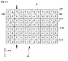
- FIG. 4 is a conceptual diagram of an imaging element array having a Bayer array in the imaging apparatus according to the first embodiment.
- FIG. 5 is a conceptual diagram of an image sensor array having a Bayer array for describing image processing for obtaining a signal value by performing demosaic processing on an electric signal obtained from the image sensor.
- FIGS. 10A, 10 ⁇ / b> B, and 10 ⁇ / b> C are diagrams schematically illustrating the imaging apparatus of Example 5 and the states of polarization in the first polarizing unit and the second polarizing unit, respectively.
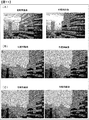
- FIG. 11 are views that replace the photographs of the left-eye image and the right-eye image obtained in the imaging apparatuses of Example 1, Example 4, and Example 5, respectively.
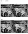
- It is. 12A and 12B are diagrams instead of photographs of the left-eye image and the right-eye image showing the results of examining the relationship between the extinction ratio and the parallax in Example 6.
- FIG. 13A, 13 ⁇ / b> B, and 13 ⁇ / b> C respectively show the relationship between the pitch of the wires constituting the wire grid polarizer, the wavelength of the incident light, and the extinction ratio, and the wire grid polarizer in Example 7.
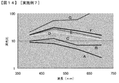
- FIG. 14 is a graph showing the results of obtaining the relationship between the length of two wires constituting the wire grid polarizer, the wavelength of incident light, and the extinction ratio in Example 7.
- FIG. 15 is a conceptual diagram of an image pickup element array having a Bayer array in the image pickup apparatus according to the eighth embodiment.
- FIG. 16 is a conceptual diagram of an imaging element array having a Bayer array in Modification 1 of the imaging apparatus according to Embodiment 8.
- FIG. 17 is a conceptual diagram of an imaging element array having a Bayer array in Modification 2 of the imaging apparatus according to Embodiment 8.
- FIG. 18 is a conceptual diagram of an imaging element array having a Bayer array in Modification 3 of the imaging apparatus according to Embodiment 8.
- FIG. 19 is a conceptual diagram of an imaging element array having a Bayer array in Modification 4 of the imaging apparatus according to Embodiment 8.
- (A), (B), (C), and (D) of FIG. 20 are the conceptual diagram of the imaging device of Example 9, the conceptual diagram of the quarter-wave plate, and the state of polarization in the first polarizing means, respectively.
- FIG. 2 is a diagram schematically showing the state of polarization in the polarization means (second polarization means).
- 21A, 21B, and 21C are a conceptual diagram of a quarter-wave plate in the imaging apparatus of Example 9, and a diagram schematically showing a polarization state in the first polarizing unit, respectively. It is a figure which shows typically the state of the polarization in a polarizing means (2nd polarizing means), (D) and (E) of FIG. 21 are the conceptual diagrams of the quarter wavelength plate in the imaging device of Example 10.
- FIG. is there. 22A and 22B are schematic partial cross-sectional views of modified examples of the image sensor.
- Example 1 Imaging apparatus and imaging method according to first to second aspects of the present disclosure
- Example 2 Modification of Example 1) 4).
- Example 3 another modification of Example 1) 5.
- Example 4 another modification of Example 1) 6).
- Example 5 another modification of Example 1) 7).
- Example 6 another modification of Example 1) 8).
- Example 7 another modification of Example 1) 9.
- Example 8 another modification of Example 1) 10.
- Example 9 an imaging device according to the second aspect of the present disclosure and another modification of Example 1) 11.
- Example 10 modification of Example 9
- the first polarization unit is disposed in the vicinity of the diaphragm portion of the lens system.
- the first polarizing means is applied to the portion of the lens system in the parallel light state.
- the first polarizing means can be fixed to the existing lens system, or can be attached detachably. Any mechanical (physical) design change may be applied.
- the first polarizing means may have a configuration and structure similar to the diaphragm blades of the lens, and may be disposed in the lens system.
- a member provided with the first polarizing means and the opening is attached to the rotation shaft so as to be rotatable about a rotation axis parallel to the optical axis of the lens system.
- a configuration and a structure in which a light beam passing through the lens system passes through the opening or through the first polarizing means can be mentioned.
- a member provided with the first polarizing means and the opening is attached to the lens system so as to be slidable in a direction orthogonal to the optical axis of the lens system, for example, and the member is slid.
- a configuration and structure in which a light beam passing through the system passes through the opening or through the first polarizing means can be mentioned.
- the first polarization unit includes the first region and the second region.
- a central region is provided between them, and the polarization state of the light passing through the central region that has passed through the central region can be set to a form that does not change from that before the central region is incident. That is, the central region can be transparent with respect to polarized light.
- the central region of the first polarizing means the light intensity is strong, but the amount of parallax is small. Therefore, by adopting such a configuration, it is possible to secure a sufficiently long baseline length of binocular parallax while increasing the light intensity received by the imaging element array.
- the central region can be circular
- the first region and the second region can be fan-shaped with a central angle of 180 degrees surrounding the central region
- the first region and the second region can be shaped like a diamond and have a shape similar to a sector having a central angle of 180 degrees surrounding the central region.
- the first region, the central region, and the second region can be formed in a strip shape extending along the second direction.
- the imaging apparatus including the various preferred embodiments described above or the imaging apparatus suitable for use in the imaging method of the present disclosure (hereinafter, these imaging apparatuses are referred to as “the first of the present disclosure.
- the first region and the second region are composed of polarizers, and the direction of the electric field of the first region passing light and the direction of the electric field of the second region passing light are It can be set as the structure orthogonally crossed.
- the direction of the electric field of the first region passing light may be configured to be parallel to the first direction, or The direction of the electric field of the light passing through the first region can be configured to form an angle of 45 degrees with the first direction.
- the direction of the electric field of the first region passing light and the direction of the electric field of the third region passing light are parallel.
- the direction of the electric field of the second region passing light and the direction of the electric field of the fourth region passing light can be configured to be parallel.
- it is desirable that the extinction ratio of the polarizer is 3 or more, preferably 10 or more.
- the “polarizer” refers to a material that generates linearly polarized light from natural light (non-polarized light) or circularly polarized light.
- the polarizer constituting the first region and the second region is itself a known structure and structure.
- a polarizer (polarizing plate) may be used.
- one polarization component of the first region passing light and the second region passing light is mainly an S wave (TE wave), and the other polarization component of the first region passing light and the second region passing light is mainly a P wave. (TM wave) may be used.
- the polarization state of the first region passing light and the second region passing light may be linearly polarized light or circularly polarized light (however, the rotation directions are opposite to each other).
- a transverse wave whose vibration direction is only in a specific direction is called a polarized wave, and this vibration direction is called a polarization direction or a polarization axis.
- the direction of the electric field of light coincides with the polarization direction.
- the extinction ratio is the direction of the electric field included in the light passing through the first region in the first region when the direction of the electric field of the light passing through the first region is parallel to the first direction. Is the ratio of the light component in the first direction to the light component in the direction of the electric field in the second direction, and in the second region, the electric field included in the light passing through the second region The ratio of the light component whose direction is the second direction and the light component whose direction of the electric field is the first direction.
- the direction of the electric field of the light passing through the first region is configured to form an angle of 45 degrees with the first direction
- the direction of the electric field included in the light passing through the first region Is the ratio of the light component forming an angle of 45 degrees with the first direction and the light component forming an angle of 135 degrees
- the electric field included in the light passing through the second region Is the ratio of the light component forming an angle of 135 degrees with the first direction and the light component forming an angle of 45 degrees.
- the polarization component of the first region passing light is mainly P wave
- the polarization component of the second region passing light is mainly S wave
- the first region passing light is changed to the first region passing light.
- the ratio of the P-polarized component and the S-polarized component included, and in the second region the ratio of the S-polarized component and the P-polarized component included in the second region passing light.
- the imaging element includes a photoelectric conversion element, and a color filter, an on-chip lens
- the wire grid polarizer may be laminated, and the wire grid polarizer may form the third region or the fourth region.
- the imaging element is formed by laminating a photoelectric conversion element and a wire grid polarizer, a color filter, and an on-chip lens on or above the photoelectric conversion element, and the wire grid polarizer is in the third region or the fourth region. It can be set as the form which comprises.
- the imaging element is formed by stacking a photoelectric conversion element and an on-chip lens, a color filter, and a wire grid polarizer on or above the photoelectric conversion element, and the wire grid polarizer is in the third region or the fourth region.
- It can be set as the form which comprises.
- the stacking order of the on-chip lens, the color filter, and the wire grid polarizer can be changed as appropriate.
- the extending direction of the plurality of wires constituting the wire grid polarizer is the first direction. Or a direction parallel to the second direction.
- the extending direction of the wire is parallel to the second direction
- the wire grid polarizer constituting the fourth region the wire The extending direction is parallel to the first direction.
- the extending direction of the plurality of wires constituting the wire grid polarizer can be configured to form 45 degrees with the first direction or the second direction.
- the wire grid polarizer composing the third region the extending direction of the wire forms an angle of 135 degrees with the first direction
- the wire grid polarizer composing the fourth region corresponds to the wire grid polarizer composing the fourth region.
- the extending direction of the wire forms an angle of 45 degrees with the first direction.
- the direction in which the wire extends becomes the light absorption axis in the wire grid polarizer, and the direction orthogonal to the direction in which the wire extends becomes the light transmission axis in the wire grid polarizer.
- the light incident side of the first polarizing means is It is desirable that a quarter wave plate ( ⁇ / 4 wave plate) is disposed.
- the quarter wave plate may be placed at all times or as desired.
- a quarter wavelength plate may be detachably attached to a filter attaching portion provided in the lens system.
- the binocular rivalry is obtained from an image obtained from a P wave component and an S wave component when imaging a subject such as a water surface or a window that reflects a P wave component but absorbs an S wave component, for example.
- the quarter-wave plate speed axis preferably forms an angle of 45 degrees or 45 degrees ⁇ 10 degrees with the direction of the electric field of the first region passing light.
- the first region and the second region are made of a polarizer, and the direction of the electric field of the first region passing light and the direction of the electric field of the second region passing light are orthogonal to each other.
- a quarter wave plate is disposed on the light incident side of the first polarizing means,
- the fast axis of the quarter-wave plate can be configured to form a predetermined angle with the direction of the electric field of the first region passing light, or alternatively
- the quarter-wave plate comprises a first quarter-wave plate and a second quarter-wave plate arranged along the second direction,
- the fast axis of the first quarter-wave plate forms a predetermined angle with the direction of the electric field of the first region passing light
- the fast axis of the second quarter wave plate is orthogonal to the fast axis of the first quarter wave plate (in
- the predetermined angle may be 45 degrees or 45 degrees ⁇ 10 degrees.
- the direction of the electric field of the first region passing light and the direction of the electric field of the third region passing light are parallel, The direction of the electric field of the second region passing light and the direction of the electric field of the fourth region passing light may be parallel to each other.
- the first polarizing means is detachably attached to the lens system
- the quarter-wave plate can be configured to be detachably attached to the lens system. Further, in these forms, the quarter-wave plate can be arranged adjacent to the first polarizing means, for example, on the light incident side of the first polarizing means.
- the quarter-wave plate comprises a first quarter-wave plate and a second quarter-wave plate arranged along the second direction,
- the fast axis of the first quarter-wave plate forms a predetermined angle with the direction of the electric field of the fifth region passing light
- the fast axis of the second quarter wave plate is orthogonal to the fast axis of the first quarter wave plate (in other words, parallel to the slow axis of the first quarter wave plate).
- the predetermined angle may be 45 degrees or 45 degrees ⁇ 10 degrees, and further includes these forms.
- the direction of the electric field of the fifth region passing light and the direction of the electric field of the sixth region passing light may be orthogonal to each other.
- the direction of the electric field of the light passing through the fifth region may be parallel to the first direction, or the direction of the electric field of the light passing through the fifth region may be 45 degrees with respect to the first direction. It can be made into a form to be formed.
- the quarter-wave plate may be detachably attached to the lens system.
- the quarter-wave plate may be configured and structured similar to the diaphragm blades of the lens and disposed in the lens system.
- a member provided with a quarter-wave plate and an opening is attached to the rotation shaft so as to be rotatable about a rotation axis parallel to the optical axis of the lens system.
- a member provided with a quarter-wave plate and an opening is attached to the lens system so as to be slidable in a direction orthogonal to the optical axis of the lens system, and the member is slid.
- a configuration and a structure in which the light beam passing through the lens system passes through the opening or through the quarter-wave plate can be given.
- the quarter-wave plate may be composed of a plurality of members, and each member may be slidable in a direction perpendicular to the optical axis of the lens system.
- a polarizing plate having an ⁇ -degree polarization axis is disposed on the light incident side of the first polarizing means,
- the first region consists of a first wave plate
- the second region consists of a second wave plate
- the direction of the electric field of the first region passing light and the direction of the electric field of the second region passing light may be orthogonal to each other.
- the value of ⁇ is 45 degrees
- the first wave plate is a half wave plate (+ ⁇ / 2 wave plate)
- the second wave plate can be constituted by a half wave plate (- ⁇ / 2 wave plate) having a phase difference different from that of the half wave plate constituting the first wave plate.
- a polarizing plate having a polarization axis of ⁇ degrees is fixed to the lens system.
- the imaging element array has a Bayer array, and one pixel is configured by four imaging elements. One third region and / or fourth region may be arranged for the pixel.
- the arrangement of the image pickup device array is not limited to the Bayer arrangement, and other than that, an interline arrangement, a G stripe RB checkered arrangement, a G stripe RB complete checkered arrangement, a checkered complementary arrangement, a stripe arrangement, an oblique stripe arrangement, a primary color difference arrangement, A field color difference sequential array, a frame color difference sequential array, a MOS type array, an improved MOS type array, a frame interleaved array, and a field interleaved array can be exemplified.
- the above description can basically be applied to the imaging apparatus according to the second aspect of the present disclosure.
- the image data for obtaining the right-eye image (right-eye image data) and the image data for obtaining the left-eye image (left-eye image data) are obtained on the basis of the electrical signal. It can.
- the above description can basically be applied to the imaging apparatus according to the second aspect of the present disclosure.
- the red image sensor that receives red and the blue image sensor that receives blue do not have the third area and the fourth area, but two that receive green.
- the third area may be arranged on one side of the green image sensor and the fourth area may be arranged on the other side.
- the array of the image sensor array is a Bayer array, one red image sensor that receives red, one blue image sensor that receives blue, and two green image sensors that receive green.
- a third region or a fourth region is arranged in two image sensors adjacent to one direction (for example, a red image sensor that receives red and one green image sensor that receives green), and the remaining two image sensors
- the fourth region or the third region may be arranged on the blue image sensor that receives blue light and the other green image sensor that receives green light.
- the array of the image sensor array is a Bayer array
- One image sensor (for example, one red image sensor that receives red light or one blue image sensor that receives blue light) is provided with a third region or a fourth region, and the image sensor has a second direction.
- the fourth region or the third region may be arranged in an adjacent image sensor (for example, a green image sensor).
- one third region and one fourth region can be arranged for N pixels along the second direction, and the first direction can be arranged along the first direction.
- one third region or one fourth region can be arranged for M pixels.
- the imaging apparatus including the various preferable modes and configurations described above or the imaging method of the present disclosure (hereinafter collectively referred to simply as “the present disclosure”)
- the first direction can be the horizontal direction and the second direction can be the vertical direction.
- the unit length may be, for example, equal to the length along the first direction of the imaging device (when the direction of the electric field of the first region passing light is parallel to the first direction), or alternatively, one imaging
- the length may be equal to the length of the element (when the direction of the electric field of the light passing through the first region forms an angle of 45 degrees with the first direction).
- the lens system may be a single focus lens or a so-called zoom lens, and the configuration and structure of the lens and the lens system may be determined based on specifications required for the lens system.
- the imaging element include a CCD sensor, a CMOS sensor, and a CMD (Charge Modulation Device) type signal amplification type image sensor.
- the imaging device examples include a front-illuminated solid-state imaging device and a back-illuminated solid-state imaging device.
- a digital still camera, a video camera, or a camcorder can be configured from the imaging devices according to the first to second aspects.
- the third region and the fourth region are configured from wire grid polarizers.
- the wire constituting the wire grid polarizer is not limited, but is made of aluminum (Al) or an aluminum alloy,
- the ratio of the wire width to the wire pitch [(wire width) / (wire pitch)] is 0.33 or more,
- the height of the wire is 5 ⁇ 10 ⁇ 8 m or more, It is preferable that the number of wires is 10 or more.
- the barycentric point of the first region refers to the barycentric point obtained based on the outer shape of the first region
- the barycentric point of the second region is the second It refers to the center of gravity obtained based on the outer shape of the region.
- the outer shape of the first polarizing means is a circle having a radius r
- the first area and the second area are half-moons occupying half of the first polarizing means
- the center of gravity of the first area and the second area The distance to the center of gravity can be obtained by [(8r) / (3 ⁇ )] from a simple calculation.
- Example 1 relates to an imaging apparatus and an imaging method according to the first aspect of the present disclosure, and more specifically, relates to an imaging apparatus and an imaging method for imaging a subject as a stereoscopic image.
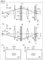
- FIG. 1A is a conceptual diagram of the image pickup apparatus according to the first embodiment, and the polarization states of the first polarizing unit and the second polarizing unit are schematically illustrated in FIG. 1B and FIG.
- FIG. 2A shows a conceptual diagram of the light that passes through the first region in the system, the first region in the first polarization unit, and the third region in the second polarization unit, and reaches the image sensor array, and shows the second in the first polarization unit.
- a conceptual diagram of light passing through the region and the fourth region in the second polarizing means and reaching the image sensor array is shown in FIG. 2B, and imaged by the light shown in FIGS. 2A and 2B
- Images formed on the element array are schematically shown in FIGS. 2C and 2D.
- the traveling direction of light is the Z-axis direction
- the first direction is the horizontal direction (X-axis direction)
- the second direction is the vertical direction (Y-axis direction).
- the imaging devices of Example 1 or Examples 2 to 10 described later are: (A) First polarization means 130, 230, 330, 430, 530, 930 for polarizing light from the subject, (B) the lens system 20 for condensing the light from the first polarizing means 130, 230, 330, 430, 530, 930, and (C)
- the imaging elements 41 are arranged in a two-dimensional matrix in a first direction (horizontal direction, X-axis direction) and a second direction (vertical direction, Y-axis direction) orthogonal to the first direction.
- An image pickup device array 40 having second polarizing means 150 and 250 on the light incident side and converting the light collected by the lens system 20 into an electric signal; It has.
- the first polarizing means 130, 230, 330, 430, 530, and 930 include first regions 131, 231, 331, 531, 931 and second regions arranged along a first direction (horizontal direction, X-axis direction).
- Regions 132, 232, 332, 532, 932 The polarization state of the first region passing light L 1 that has passed through the first regions 131, 231, 331, 531, 931 and the second region passing light L 2 that has passed through the second regions 132, 232, 332, 532, and 932 Unlike the polarization state,
- the second polarizing means 150, 250 are alternately arranged along the second direction (vertical direction, Y-axis direction), and a plurality of third regions 151, extending in the first direction (horizontal direction, X-axis direction).
- the polarization state of the third region passing light L 3 that has passed through the third regions 151 and 251 is different from the polarization state of the fourth region passing light L 4 that has passed through the fourth regions 152 and 252,
- the first region passing light L 1 passes through the third regions 151 and 251 and reaches the image sensor 41
- the second region passing light L 2 passes through the fourth regions 152 and 252 and reaches the image sensor 41, Therefore, the distance between the centroid point BC 1 of the first areas 131, 231, 331, 531, 931 and the centroid point BC 2 of the second areas 132, 232, 332, 532, 932 is the baseline length of binocular parallax.
- An image for obtaining a stereoscopic image is taken.
- the lens system 20 includes, for example, a photographing lens 21, a diaphragm unit 22, and an imaging lens 23, and serves as a zoom lens.
- the taking lens 21 is a lens for collecting incident light from the subject.
- the photographic lens 21 includes a focus lens for focusing, a zoom lens for enlarging a subject, and the like, and is generally realized by a combination of a plurality of lenses to correct chromatic aberration and the like.
- the diaphragm 22 has a function of narrowing down in order to adjust the amount of collected light, and is generally configured by combining a plurality of plate-shaped blades.
- the imaging lens 23 images the light that has passed through the first polarization means 130, 230, 330, 430, 530, and 930 onto the image sensor array 40.
- the image sensor array 40 is disposed inside the camera body 11. In the above configuration, the entrance pupil is located closer to the camera body than the imaging lens 23.
- a digital still camera, a video camera, and a camcorder are configured from the imaging device.
- the camera body unit 11 includes, for example, an image processing unit 12 and an image storage unit 13 in addition to the image sensor array 40. Then, right-eye image data and left-eye image data are formed based on the electrical signals converted by the image sensor array 40.
- the imaging element array 40 is realized by, for example, a CCD (Charge Coupled Devices), a CMOS (Complementary Metal Oxide ⁇ Semiconductor) image sensor, or the like.
- the image processing means 12 converts the electrical signal output from the image sensor array 40 into right-eye image data and left-eye image data, and records them in the image storage unit 13.
- the first polarizing means 130, 230, 330, 430, 530, and 930 are arranged in the vicinity of the diaphragm unit 22 of the lens system 20. Specifically, the first polarizing means 130, 230, 330, 430, 530, and 930 are arranged as close to the diaphragm unit 22 as possible as long as they do not hinder the operation of the diaphragm unit 22.
- the first polarizing means 130, 230, 330, 430, 530, and 930 as described above, the light incident on the lens system 20 is once converted into parallel light and finally condensed on the image sensor 41 ( When the image is formed, the lens system 20 is arranged in a parallel light state.
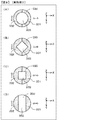
- the first polarization unit 130 includes a first region 131 and a second region 132.
- the outer shape of the first polarizing means 130 is circular, and each of the first region 131 and the second region 132 has a half-moon shaped outer shape that occupies half of the first polarizing means 130.
- the boundary line between the first region 131 and the second region 132 extends along the second direction.
- the first polarization means 130 comprising a combination of two polarization filters separates incident light into two different polarization states.
- the first polarizing means 130 is composed of left-right symmetric polarizers, and linearly polarized light that is orthogonal to each other or rotated in opposite directions at two left and right positions with respect to the upright state of the camera. Generates directional polarization.
- the first region 131 is a filter that polarizes an image that the subject will see with the right eye (light that the right eye will receive).
- the second region 132 is a filter that polarizes an image that the subject will see with the left eye (light that the left eye will receive).
- the first region 131 and the second region 132 are made of a polarizer.
- the direction of the electric field of the first region passing light L 1 (indicated by a white arrow) is orthogonal to the direction of the electric field of the second region passing light L 2 (indicated by a white arrow) (FIG. 1). (See (B)).
- the direction of the electric field of the first region passing light L 1 is parallel to the first direction.
- the first region passing light L 1 mainly has a P wave (TM wave) as a polarization component
- the second region passing light L 2 mainly has an S wave (TE wave) as a polarization component.
- the direction of the electric field of the first region passing light L 1 and the direction of the electric field of the third region passing light L 3 are parallel, and the electric field of the second region passing light L 2
- the direction and the direction of the electric field of the fourth region passing light L 4 are parallel (see FIG. 1C).
- the extinction ratio of each polarizer is 3 or more, more specifically 10 or more.
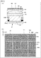
- FIG. 3A A schematic partial cross-sectional view is shown in FIG. 3A, and the arrangement state of the wire grid polarizer 67 is schematically shown in FIG. 3B.
- a child 67 is laminated.
- the wire grid polarizer 67 constitutes the third region 151 and the fourth region 152, respectively.
- the boundary region of the pixel is indicated by a solid line.
- the extending direction of the plurality of wires 68 constituting the wire grid polarizer 67 is parallel to the first direction or the second direction. Specifically, in the wire grid polarizer 67A constituting the third region 151, the extending direction of the wire 68A is parallel to the second direction, and the wire grid polarizer 67B constituting the fourth region 152 is In this case, the extending direction of the wire 68B is parallel to the first direction.
- the direction in which the wire 68 extends becomes the light absorption axis in the wire grid polarizer 67, and the direction orthogonal to the direction in which the wire 68 extends becomes the light transmission axis in the wire grid polarizer 67.
- an electrical signal for obtaining right-eye image data is obtained from the first region passing light L 1 that has passed through the third region 151 and reached the imaging device 41.
- an electrical signal for obtaining image data for the left eye is generated in the imaging device 41 by the second region passing light L 2 that has passed through the fourth region 152 and reached the imaging device 41.
- These electric signals are output simultaneously or alternately in time series.
- the output electrical signal (the electrical signal for obtaining the image data for the right eye and the image data for the left eye output from the image sensor array 40) is subjected to image processing by the image processing means 12, and is used for the right eye.
- the image data is recorded in the image storage unit 13 as image data and left-eye image data.
- the lens system 20 is focused on a square object A as schematically shown in FIGS. Further, it is assumed that the round object B is located closer to the lens system 20 than the object A.
- An image of the square object A is formed on the image sensor array 40 in a focused state.
- the round object B image is formed on the image sensor array 40 in a state where it is not in focus.
- the object B forms an image at a position separated by a distance (+ ⁇ X) on the right hand side of the object A on the image sensor array 40.
- the object B forms an image at a position separated by a distance ( ⁇ X) on the left hand side of the object A.
- the distance (2 ⁇ ⁇ X) is information regarding the depth of the object B. That is, the blur amount and blur direction of an object located closer to the imaging device than the object A are different from the blur amount and blur direction of an object located far from the imaging device, and the distance between the object A and the object B The amount of blur of the object B differs depending on. Then, it is possible to obtain a stereoscopic image in which the distance between the barycentric positions of the shapes of the first region 131 and the second region 132 in the first polarizing unit 130 is the binocular parallax baseline length. That is, from the right-eye image (see the schematic diagram in FIG. 2C) and the left-eye image (see the schematic diagram in FIG.
- a three-dimensional image is obtained based on a known method.
- An image can be obtained. Note that if the right-eye image data and the left-eye image data are mixed, a normal two-dimensional (planar) image that is not a stereoscopic image can be obtained.
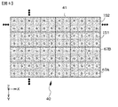
- the image sensor array 40 has a Bayer array, and one pixel has four image sensors (one red image sensor R that receives red, blue color). It is composed of one blue image sensor B that receives light and two green image sensors G that receive green.
- a third region 151 is arranged for a group of pixels arranged in one row along the first direction. Similarly, the third region 151 is adjacent to the pixel group in the second direction and extends in the first direction.
- a fourth region 152 is arranged for one row of pixel groups arranged along the line. The third regions 151 and the fourth regions 152 are alternately arranged along the second direction.
- the third region 151 and the fourth region 152 extend in the first direction as a whole, but the unit length along the first direction and the second direction of the third region 151 and the fourth region 152 is
- the length of the image sensor 41 is equal to the length along the first direction and the second direction.
- the electrical signals for the right-eye image data and the left-eye image data are generated in a kind of tooth missing state along the second direction. Therefore, the image processing unit 12 performs demosaic processing on the electrical signal to create right-eye image data and left-eye image data, and performs interpolation processing based on super-resolution processing, for example, Finally, image data for the right eye and image data for the left eye are generated and created. Also, for example, a parallax detection technique for creating a disparity map (Disparity Map) by stereo matching from image data for the left eye and image data for the right eye, and parallax control for controlling the parallax based on the disparity map The technique can also enhance parallax or make it appropriate.
- a parallax detection technique for creating a disparity map (Disparity Map) by stereo matching from image data for the left eye and image data for the right eye
- parallax control for controlling the parallax based on the disparity map
- the technique can also enhance parallax or
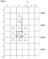
- FIG. 5 shows a conceptual diagram of an image sensor array having a Bayer array for explaining image processing (mosaic processing) for performing a demosaic process on an electric signal obtained from the image sensor and obtaining a signal value.
- FIG. 5 shows an example of generating a signal value related to the green image sensor in the left eye image.
- image processing mosaic processing
- FIG. 5 shows an example of generating a signal value related to the green image sensor in the left eye image.
- demosaic processing an average value of electrical signals of image sensors of the same color in the vicinity is generally used.
- the pixel group (pixel row) for obtaining the right-eye image data and the pixel group (pixel row) for obtaining the left-eye image data are alternately repeated as in the first embodiment, the state is unchanged. If the values in the vicinity are used, the original image data may not be obtained. Therefore, the demosaic processing is performed in consideration of which of the right-eye image data and the left-eye image data corresponds to the electrical signal of the image sensor to be
- g ′ 4,2 (g 4,1 + g 4,3 + g 5,2 + g 1,2 ⁇ W 3 ) / (3.0 + W 3 )
- g ′ i, j on the left side is the green image sensor signal value at the position (i, j).
- g i, j on the right side is the value of the electrical signal of the green image sensor at position (i, j).
- “3.0” is the distance (W 1 ) from the image sensor G 4,2 to the adjacent image sensors G 4,1 , G 4,3 , G 5,2 , for example, “1.0”.
- the reciprocal of the weight is used as a weight and corresponds to the sum of the weights.
- W 3 is a weight for the value of the electric signal of the image sensor G 1,2 separated by three image sensors, and in this case, “1/3”.
- the demosaic processing can be performed on the red image sensor R and the blue image sensor B according to the same concept.
- the image sensor signal value at each image sensor position can be obtained by demosaic processing, but at this stage, as described above, there is a kind of tooth missing state. Therefore, it is necessary to generate an image sensor signal value by interpolation for an area where no image sensor signal value exists.
- an interpolation method a known method such as a method of using an average value of neighboring values can be used. This interpolation process may be performed in parallel with the demosaic process. Since the image quality is completely maintained in the first direction, image quality degradation such as a reduction in resolution of the entire image is relatively small.
- the imaging device 110 is configured by a set of the first polarizing unit 130, the second polarizing unit 150, and one lens system 20, for example, two different images separated into the left and right are generated simultaneously. Therefore, it is possible to provide a small-sized imaging device that has a simple structure and structure and has few components. Further, since two pairs of lenses and polarizing filters are not required, there is no deviation or difference in zoom, aperture, focus, convergence angle, and the like. Moreover, since the baseline length of binocular parallax is relatively short, a natural stereoscopic effect can be obtained. Furthermore, if the first polarizing means 130 is structured to be removable, a two-dimensional image and a three-dimensional image can be easily obtained.
- the second embodiment is a modification of the first embodiment.
- the direction of the electric field of the first region passing light L 1 was set parallel to the first direction.
- the orientation of the first field region transmission light L 1 forms an angle to the first direction 45 degrees.
- FIGS. 6A and 6B schematically show the polarization states of the first polarizing means 230 and the second polarizing means 250 provided in the imaging apparatus of the second embodiment.
- FIG. 7 shows a conceptual diagram of the image sensor array 40 having a Bayer array.
- the image sensor array 40 receives four image sensors (one red image sensor R that receives red light, one blue image sensor B that receives blue light, and green light). It is composed of two green image sensors G).
- the third region 251 is arranged for a group of pixels arranged in one row along the first direction.
- the third region 251 is adjacent to the pixel group in the second direction and extends in the first direction.
- a fourth region 252 is arranged for a group of pixels arranged along one row.
- the third region 251 and the fourth region 252 are alternately arranged along the second direction.
- the unit length of the third region 251 and the fourth region 252 is equal to the length of one image sensor. And by setting it as such a structure, the 1st based on the strip
- oblique lines are attached to the inside of the third region 251 and the fourth region 252, which schematically represent wires of a wire grid polarizer.
- the configuration and structure of the imaging apparatus according to the second embodiment can be the same as the configuration and structure of the imaging apparatus 110 described in the first embodiment, and thus detailed description thereof is omitted.
- the configuration and structure of the imaging apparatus according to the second embodiment can be applied to imaging apparatuses according to third to tenth embodiments which will be described later.
- Example 3 is also a modification of Example 1.
- the central region 333 is provided between the first region 331 and the second region 332, and the central region passing light that has passed through the central region 333 is provided.
- the polarization state of is not changed from that before the incidence on the central region 333. That is, the central region 333 is in a transparent state with respect to polarized light.
- the extinction ratio is a ratio between the amount of light that the polarizer selects and passes and the amount of light leakage that is not selected by the polarizer but reflected or absorbed.
- the P-wave component In the case of a polarizer that transmits a P-wave component having an extinction ratio ⁇ , the P-wave component is transmitted 100% and the S-wave component is totally reflected or completely absorbed and not transmitted.
- the brightness is about 1/2.
- the amount of light that has passed through the first polarizing means 130 and the second polarizing means 150 shown in FIGS. 1B and 1C is the light before entering the first polarizing means 130 even if the transmission loss is zero. It will be about 25% of the amount of light.
- the baseline length of binocular parallax is short in proportion to the mixed ratio.
- the left-eye image and the right-eye image are the same image, so that the parallax cannot be taken and stereoscopic viewing cannot be performed.
- the first polarizing means 330 of the third embodiment it is possible to secure a sufficiently long binocular parallax baseline length while increasing the light intensity received by the imaging device array 40.
- the central region 333 is circular, and the first region 331 and the second region 332 are formed.
- the central region 333 is a rhombus or a square
- the first region 331 and the second region 332 are the central region 333.
- the first region 331, the central region 333, and the second region 332 have a band-like shape extending along the second direction. can do.
- the configuration and structure of the imaging apparatus according to the third embodiment can be the same as the configuration and structure of the imaging apparatus 110 described in the first embodiment, and thus detailed description thereof is omitted.
- the configuration and structure of the imaging apparatus according to the third embodiment can be applied to the imaging apparatuses according to the fourth to tenth embodiments described later.
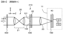
- FIG. 9 shows a conceptual diagram of the imaging device 410 of the fourth embodiment.
- a quarter-wave plate ( ⁇ / 4 wave plate) 433 is disposed on the light incident side of the first polarizing unit 430, and thereby, a so-called binocular rivalry. Occurrence can be avoided.
- the quarter wavelength plate 433 may be detachably attached to a filter attachment portion provided in the lens system. The light that has passed through the quarter-wave plate 433 is in a state where the polarization directions are aligned (linearly polarized state).
- Example 4 the first region passing light L 1 mainly has S wave (TE wave) as a polarization component, and the second region passing light L 2 mainly has P wave (TM wave) as a polarization component. It was set as the structure which has as.
- the image for the left eye and the image for the right eye in FIG. 11A obtained by the imaging device 110 described in the first embodiment are compared, for example, the glass window in the region indicated by “A” and the glass window It can be seen that the light reflection state in the glass window located on the lower side is particularly different. Therefore, when imaging a subject that reflects the P wave component but absorbs the S wave component, the image obtained from the P wave component and the image obtained from the S wave component are presented to both eyes. It does not occur, and there is a visual field conflict in which only one of the images is dominantly viewed alternately or is suppressed in the overlapping area.
- the configuration and structure of the imaging device 410 according to the fourth embodiment can be applied to the imaging devices according to the sixth to eighth embodiments described later.
- the fast axis of the quarter-wave plate 433 is equal to the direction of the electric field of the first region passing light and a predetermined angle (specifically, 45 degrees in the imaging device described in the first or second embodiment). An angle or an angle of 45 ° ⁇ 10 °).
- FIG. 10A shows a conceptual diagram of the imaging apparatus 510 of Example 5, and FIGS. 10B and 10C schematically show the polarization states of the first polarizing means and the second polarizing means.
- a polarizing plate 534 having a polarization axis of ⁇ degrees is disposed on the light incident side of the first polarizing unit 530 in order to avoid the occurrence of a visual field conflict.
- the first region 531 is composed of a first wavelength plate
- the second region 532 is composed of a second wavelength plate.
- the direction of the electric field of the first region passing light L 1 and the direction of the electric field of the second region passing light L 2 are Are orthogonal.
- the value of ⁇ is 45 degrees
- the first wavelength plate constituting the first region 531 is composed of a half-wave plate (+ ⁇ / 2 wavelength plate), and the second wavelength constituting the second region 532.
- the plate is a half-wave plate (- ⁇ / 2 wave plate) having a phase difference different from that of the half-wave plate constituting the first wave plate.
- FIG. 11C shows a left eye image (an image on the left hand side in FIG. 11C) and an image for the right eye (an image on the right hand side in FIG. 11C).
- the image for the left eye and the image for the right eye in FIG. 11C obtained by the imaging device 510 according to the fifth embodiment are compared, for example, a glass window in an area indicated by “A” as in the fourth embodiment.
- the reflection state of light in the glass window located below the glass window is almost the same, and the occurrence of the binocular rivalry can be avoided.
- the configuration and structure of the imaging device 510 in Embodiment 5 can be applied to imaging devices in Embodiments 6 to 10, which will be described later.
- Example 6 is also a modification of Example 1.
- Extinction ratio 1 (50% crosstalk from the state where the image for the eye is separated), and the image for the left eye and the image for the right eye are completely mixed, the image for the left eye and the right eye
- the composite image simulation was performed while changing the extinction ratio until the image was the same as the image for use. A part of the result is shown in FIGS.
- the left-hand side view (left-eye image) and the right-hand side view (right-eye image) have the same distance between the solid line and the dotted line extending in the vertical direction.
- the nose position of the gypsum image located behind the apple is A slight difference.
- the difference in the position of the nose of the gypsum image is less in FIG.
- the extinction ratio of the polarizer is desirably 3 or more.
- Example 7 is also a modification of Example 1.
- the relationship between the specifications of the wire grid polarizer and the extinction ratio was obtained by calculation.
- FIG. 13A shows the relationship between the pitch of the wires constituting the wire grid polarizer, the wavelength ( ⁇ ) of incident light, and the extinction ratio.
- the wire width was 1/3 of the wire pitch
- the wire height was 150 nm
- the wire length was infinite.
- the curve “A” is the data when the pitch is 150 nm
- the curve “B” is the data when the pitch is 175 nm
- the curve “C” is the data when the pitch is 200 nm.
- the curve “D” is data when the pitch is 250 nm
- the curve “E” is data when the pitch is 300 nm.
- FIG. 13B shows the relationship between the height of the wires constituting the wire grid polarizer, the wavelength ( ⁇ ) of incident light, and the extinction ratio. The wire width was 50 nm, the wire length was infinite, and the wire pitch was 150 nm.
- the curve “A” is data when the height is 250 nm
- the curve “B” is data when the height is 200 nm
- the curve “C” is data when the height is 150 nm.
- Curve “D” is data for a height of 100 nm. Further, FIG.
- 13C shows the relationship between the (width / pitch) of the wire constituting the wire grid polarizer, the wavelength ( ⁇ ) of the incident light, and the extinction ratio.
- the wire width was 50 nm
- the wire height was 150 nm
- the wire length was infinite.
- the curve “A” is data when the value of (width / pitch) is 0.50
- the curve “B” is data when the value of (width / pitch) is 0.33. It is data.
- the pitch of the wire is desirably 200 nm or less, and the height of the wire is 5 ⁇ 10 ⁇ 8 m (50 nm) or more. It was found that the value of (width / pitch) of the wire is desirably 0.33 or more. Furthermore, it is preferable that the number of wires is 10 or more.
- FIG. 14 shows the relationship between the length of the two wires, the wavelength ( ⁇ ) of the incident light, and the extinction ratio.
- the wire width was 50 nm
- the wire height was 150 nm
- the wire pitch was three times the wire width.
- “A” is data when the length is 1 ⁇ m
- “B” is data when the length is 2 ⁇ m
- “C” is data when the length is 3 ⁇ m
- “D” is Data for 4 ⁇ m length
- E for 5 ⁇ m length
- G for infinite length data It is. From FIG. 14, it was found that the wire length should be 2 ⁇ m or more, preferably 3 ⁇ m or more in order to make the extinction ratio 10 or more.
- the material constituting the wire is preferably aluminum or an aluminum alloy because of the ease of processing.
- the eighth embodiment is also a modification of the first embodiment.
- N is a natural number of 1 to 5
- a depth map depth information based on the amount of parallax generated from the electrical signal obtained by the first region passage light that has passed through the third region 151 and the electrical signal obtained by the second region passage light that has passed through the fourth region 152.
- the method itself can be a well-known method.
- the demosaic process may be performed based on all electrical signals including all of the imaging elements in which the third area and the fourth area are arranged and the imaging elements that are not arranged, or imaging in which the third area and the fourth area are arranged. It is also possible to generate image data by interpolating the thinned-out portion of the element group by super-resolution processing. Further, the image quality and the number of pixels of the depth map do not have to be 1: 1 with respect to the image quality and the number of pixels.
- FIG. 16 shows a conceptual diagram of an imaging element array having a Bayer arrangement in Modification 1 of the imaging apparatus of Embodiment 8, and one third region is provided for two pixels along the first direction. 151 and one fourth region 152 may be arranged.
- the third region 151 and the fourth region 152 are arranged in a staggered pattern (checkered pattern). That is, along the second direction, it is adjacent to the fourth region 152 at one boundary of the third region 151, but is not adjacent to the fourth region 152 at the other boundary of the third region 151.
- FIG. 17 shows a conceptual diagram of an image pickup device array having a Bayer arrangement in the second modification of the image pickup apparatus of the eighth embodiment.
- the red image pickup device R that receives red and the blue image pickup device B that receives blue are shown in FIG.
- the third region 151 and the fourth region 152 may not be disposed, and the third region 151 may be disposed on one of the two green imaging elements G that receive green, and the fourth region 152 may be disposed on the other.
- FIG. 18 is a conceptual diagram of an image pickup device array having a Bayer array in Modification 3 of the image pickup apparatus according to the eighth embodiment.
- a third region 151 is arranged on one of two green image pickup devices G that receive green light.
- the region 151 and one fourth region 152 may be arranged. Further, as shown in FIG. 19, the third region 151 and the fourth region 152 may be arranged in a staggered pattern (checkered pattern).
- Example 9 relates to the imaging apparatus according to the second aspect of the present disclosure, and is a modification of the imaging apparatuses of Examples 1 to 3 and Examples 5 to 8.
- a conceptual diagram of the imaging apparatus of Example 9 is shown in FIG. 20A
- a conceptual diagram of a quarter-wave plate is shown in FIG. 20B
- the state of polarization in the first polarizing means is schematically shown.
- FIG. 20C shows the state of polarization in the polarizing means (second polarizing means) schematically shown in FIG.
- the imaging elements 41 are arranged in a two-dimensional matrix in a first direction (horizontal direction, X-axis direction) and a second direction (vertical direction, Y-axis direction) orthogonal to the first direction.
- An imaging element array 40 having polarization means 150 and 250 on the light incident side and converting the light collected by the lens system 20 into an electric signal; It has.
- the polarization means 150, 250 are alternately arranged along the second direction (vertical direction, Y-axis direction), and a plurality of fifth regions 151, extending in the first direction (horizontal direction, X-axis direction). 251 and sixth regions 152, 252
- the polarization state of the fifth region passing light that has passed through the fifth regions 151 and 251 is different from the polarization state of the sixth region passing light that has passed through the sixth regions 152 and 252,
- the fast axis of quarter-wave plate 933 (shown by a black arrow in FIGS. 20B, 21A, 21D, and 21E) is the fifth region passing light. It forms a predetermined angle with the direction of the electric field.
- the predetermined angle is 45 degrees or 45 degrees ⁇ 10 degrees.
- the direction of the electric field of the fifth region passing light and the direction of the electric field of the sixth region passing light are orthogonal.
- the direction of the electric field of the light passing through the fifth region is parallel to the first direction (see FIG. 20D), or the direction of the electric field of the light passing through the fifth region is 45 degrees from the first direction.
- An angle is formed (see FIG. 21C).
- the quarter-wave plate 933 has a configuration and structure similar to a lens diaphragm blade, and is disposed in the lens system 20.
- a quarter-wave plate 933 is disposed on the light incident side of the first polarizing unit 930.
- the fast axis of the quarter-wave plate 933 forms a predetermined angle with the direction of the electric field of the first region passing light L 1 .
- the direction of the electric field of the first region passing light L 1 and the direction of the electric field of the third region passing light L 3 are parallel, and the direction of the electric field of the second region passing light L 2 and the fourth region passing light L 4 The direction of the electric field is parallel.
- the first polarizing means 930 is detachably attached to the lens system 20, and the quarter-wave plate 933 is also detachably attached to the lens system 20.
- a quarter wave plate 933 is disposed adjacent to the first polarizing means 930.
- the quarter-wave plate 933 and the first polarization unit 930 are illustrated in this order from the light incident side. However, in some cases, the first polarization unit 930 and the quarter-wavelength are illustrated. You may arrange
- a quarter-wave plate 933 and the first polarizing means 930 are arranged in this order from the light incident side, and the quarter-wave plate 933 and the first polarizing means 930 are arranged in the lens system to provide a three-dimensional image (stereoscopic image).
- the first polarizing means 930 is disposed in the lens system, and the quarter-wave plate 933 is removed from the lens system to capture a three-dimensional image (stereoscopic image). It is possible to take a two-dimensional image by disposing the quarter-wave plate 933 in the lens system and removing the first polarizing means 930 from the lens system.
- the first polarizing means 930 and the quarter wavelength plate 933 are arranged in this order from the light incident side, the first polarizing means 930 is arranged in the lens system, and the quarter wavelength plate 933 is removed from the lens system.
- a three-dimensional image can be captured, and a two-dimensional image can be captured by disposing the quarter-wave plate 933 in the lens system and removing the first polarizing means 930 from the lens system.
- the fast axis of the quarter-wave plate 933 indicated by the black arrow extending in the upper right 45 degree direction in FIG. 20B is not limited to such a direction, and extends in the upper left 45 degree direction. Also good.
- FIG. 21 (A), (B), and (C), a conceptual diagram of a quarter-wave plate in the imaging apparatus of Example 9, the state of polarization in the first polarizing means, and the polarizing means (first A modification of the state of polarization in the two-polarization means) is illustrated, but this example is a modification of the second embodiment shown in FIG.
- the third region (fifth region) 151, 251 is obtained if the light incident on the imaging device contains linearly polarized light. There is a difference between the intensity of the light that has passed through and the intensity of the light that has passed through the fourth regions (sixth regions) 152 and 252, and the obtained two-dimensional image shows the density of the striped light. May occur.
- the fast axis is a quarter wavelength that forms a predetermined angle (specifically, 45 degrees or 45 degrees ⁇ 10 degrees) with the direction of the electric field of the fifth region passing light.
- the plate 933 Since the plate 933 is incorporated, the linearly polarized light incident on the quarter-wave plate 933 is emitted from the quarter-wave plate 933 as circularly polarized light. Therefore, the difference between the intensity of the light that has passed through the third area (fifth area) 151 and 251 and the intensity of the light that has passed through the fourth area (sixth area) 152 and 252 is unlikely to be obtained. In addition, there is no possibility that stripes of light and darkness are generated in the two-dimensional image.
- Example 10 is a modification of Example 9.
- FIG. 21D or FIG. 21E a conceptual diagram of the quarter-wave plate in the imaging apparatus of the tenth embodiment is shown in FIG.
- the first quarter-wave plate 933A and the second quarter-wave plate 933B arranged along the two directions.
- the first quarter-wave plate 933A and the second quarter-wave plate 933B are integrated.
- the fast axis of the first quarter-wave plate 933A forms a predetermined angle with the direction of the electric field of the fifth region passing light
- the fast axis of the second quarter-wave plate 933B is the first It is orthogonal to the fast axis of the quarter-wave plate 933A of one.
- the imaging apparatus according to the tenth embodiment has the same configuration and structure as the imaging apparatus according to the ninth embodiment, and thus detailed description thereof is omitted.
- the intensity of the light that has passed through the fourth regions (sixth regions) 152 and 252 are less likely to occur.
- the present disclosure has been described based on the preferred embodiments, the present disclosure is not limited to these embodiments.
- the configurations and structures of the imaging apparatus and the imaging element described in the embodiments are examples, and can be changed as appropriate.
- the image sensor 41 includes a photoelectric conversion element 61 provided on the silicon semiconductor substrate 60, and a first planarization thereon.
- the film 62, the inorganic insulating base layer 66, the wire grid polarizer 67, the second planarizing film 65, the color filter 63, and the on-chip lens 64 may be laminated.
- the imaging element 41 includes a photoelectric conversion element 61 provided on the silicon semiconductor substrate 60, and a first flat surface on the photoelectric conversion element 61. It is also possible to adopt a configuration in which the chemical film 62, the on-chip lens 64, the second planarizing film 65, the color filter 63, the inorganic insulating base layer 66, and the wire grid polarizer 67 are laminated. Further, the imaging device may be a front-side irradiation type as shown, or a back-side irradiation type (not shown).
- a stereoscopic image is displayed based on the image data for the right eye and the image data for the left eye.
- a display method for example, a circularly polarized light or a linearly polarized light filter is attached to two projectors to display images for the left and right eyes. And a method of observing an image with circularly or linearly polarized glasses corresponding to display, a lenticular lens method, and a parallax barrier method. If an image is observed without using circularly polarized light or linearly polarized glasses, a normal two-dimensional (planar) image can be observed.
- the processing procedure described above may be regarded as a method having a series of these procedures, or may be regarded as a program for causing a computer to execute the series of procedures or a recording medium storing the program.
- a recording medium for example, a CD (Compact Disc), an MD (MiniDisc), a DVD (Digital Versatile Disc), a memory card, a Blu-ray Disc (Blu-ray Disc (registered trademark)), or the like can be used.
- Image sensor 150, 250... Second polarization means (polarization means), 151 251 ... 3rd area
Landscapes
- Physics & Mathematics (AREA)
- Engineering & Computer Science (AREA)
- Multimedia (AREA)
- Signal Processing (AREA)
- General Physics & Mathematics (AREA)
- Optics & Photonics (AREA)
- Spectroscopy & Molecular Physics (AREA)
- Surgery (AREA)
- Radiology & Medical Imaging (AREA)
- Astronomy & Astrophysics (AREA)
- General Health & Medical Sciences (AREA)
- Health & Medical Sciences (AREA)
- Computing Systems (AREA)
- Theoretical Computer Science (AREA)
- Testing, Inspecting, Measuring Of Stereoscopic Televisions And Televisions (AREA)
- Stereoscopic And Panoramic Photography (AREA)
- Studio Devices (AREA)
- Polarising Elements (AREA)
- Blocking Light For Cameras (AREA)
Priority Applications (5)
| Application Number | Priority Date | Filing Date | Title |
|---|---|---|---|
| KR1020127029694A KR101785754B1 (ko) | 2010-05-28 | 2011-05-19 | 촬상 장치 및 촬상 방법 |
| US13/697,175 US9077978B2 (en) | 2010-05-28 | 2011-05-19 | Image-capturing apparatus and image-capturing method |
| EP11786550.1A EP2579568B1 (en) | 2010-05-28 | 2011-05-19 | Imaging device and imaging method |
| CN201180030777.7A CN102948141B (zh) | 2010-05-28 | 2011-05-19 | 图像捕获装置和图像捕获方法 |
| US14/750,605 US20160029005A1 (en) | 2010-05-28 | 2015-06-25 | Image-capturing apparatus and image-capturing method |
Applications Claiming Priority (4)
| Application Number | Priority Date | Filing Date | Title |
|---|---|---|---|
| JP2010-122820 | 2010-05-28 | ||
| JP2010122820 | 2010-05-28 | ||
| JP2011089238 | 2011-04-13 | ||
| JP2011-089238 | 2011-04-13 |
Related Child Applications (2)
| Application Number | Title | Priority Date | Filing Date |
|---|---|---|---|
| US13/697,175 A-371-Of-International US9077978B2 (en) | 2010-05-28 | 2011-05-19 | Image-capturing apparatus and image-capturing method |
| US14/750,605 Continuation-In-Part US20160029005A1 (en) | 2010-05-28 | 2015-06-25 | Image-capturing apparatus and image-capturing method |
Publications (1)
| Publication Number | Publication Date |
|---|---|
| WO2011148851A1 true WO2011148851A1 (ja) | 2011-12-01 |
Family
ID=45003842
Family Applications (1)
| Application Number | Title | Priority Date | Filing Date |
|---|---|---|---|
| PCT/JP2011/061521 Ceased WO2011148851A1 (ja) | 2010-05-28 | 2011-05-19 | 撮像装置及び撮像方法 |
Country Status (6)
| Country | Link |
|---|---|
| US (1) | US9077978B2 (enExample) |
| EP (1) | EP2579568B1 (enExample) |
| JP (1) | JP2012230341A (enExample) |
| KR (1) | KR101785754B1 (enExample) |
| CN (1) | CN102948141B (enExample) |
| WO (1) | WO2011148851A1 (enExample) |
Cited By (5)
| Publication number | Priority date | Publication date | Assignee | Title |
|---|---|---|---|---|
| JP2013130598A (ja) * | 2011-12-20 | 2013-07-04 | Ricoh Co Ltd | ワイヤグリッド素子ならびに該ワイヤグリッド素子を用いた偏光画像撮像装置及びプロジェクタ |
| WO2013114891A1 (ja) * | 2012-02-03 | 2013-08-08 | パナソニック株式会社 | 撮像装置および撮像システム |
| WO2015015717A1 (ja) * | 2013-07-30 | 2015-02-05 | パナソニックIpマネジメント株式会社 | 撮像装置、並びにそれを用いた撮像システム、電子ミラーシステムおよび測距装置 |
| US11284046B2 (en) | 2018-05-14 | 2022-03-22 | Sony Semiconductor Solutions Corporation | Imaging element and imaging device for controlling polarization of incident light |
| CN115205752A (zh) * | 2022-07-22 | 2022-10-18 | 深圳康荣电子有限公司 | 一种基于智能显示的液晶拼接lcd方法及系统 |
Families Citing this family (15)
| Publication number | Priority date | Publication date | Assignee | Title |
|---|---|---|---|---|
| JP5531483B2 (ja) * | 2008-08-29 | 2014-06-25 | ソニー株式会社 | 撮像装置および映像記録再生システム |
| JP2013031054A (ja) * | 2011-07-29 | 2013-02-07 | Ricoh Co Ltd | 撮像装置及びこれを備えた物体検出装置、並びに、光学フィルタ及びその製造方法 |
| WO2013114888A1 (ja) | 2012-02-02 | 2013-08-08 | パナソニック株式会社 | 撮像装置 |
| JP5974658B2 (ja) * | 2012-06-19 | 2016-08-23 | ソニー株式会社 | 撮像装置 |
| CN104049438B (zh) * | 2014-07-10 | 2017-05-24 | 王金志 | 一种矫正透视变形照相机 |
| KR102299575B1 (ko) | 2015-03-09 | 2021-09-07 | 삼성전자주식회사 | 위상 검출 픽셀들로부터 깊이 맵을 생성할 수 있는 이미지 신호 프로세서와 이를 포함하는 장치 |
| CN105372903A (zh) * | 2015-12-08 | 2016-03-02 | 苏州佳像视讯科技有限公司 | 一种ccd焦距快速调整装置 |
| JP6434947B2 (ja) * | 2016-09-30 | 2018-12-05 | キヤノン株式会社 | 撮像システム、画像処理装置、画像処理方法、及びプログラム |
| CN110381796B (zh) * | 2017-03-08 | 2022-04-22 | 索尼奥林巴斯医疗解决方案公司 | 医疗设备与制造医疗设备的方法 |
| US10365554B1 (en) | 2018-04-04 | 2019-07-30 | Intuitive Surgical Operations, Inc. | Dynamic aperture positioning for stereo endoscopic cameras |
| CN110874829B (zh) * | 2018-08-31 | 2022-10-14 | 北京小米移动软件有限公司 | 图像处理方法及装置、电子设备及存储介质 |
| KR102714205B1 (ko) * | 2019-02-28 | 2024-10-10 | 삼성전자주식회사 | 이미지 센서 |
| DE102019204759A1 (de) * | 2019-04-03 | 2020-10-08 | Richard Wolf Gmbh | Endoskopisches Instrument |
| US12359554B2 (en) * | 2021-03-15 | 2025-07-15 | Saudi Arabian Oil Company | Real-time multimodal radiometry for subsurface characterization during high-power laser operations |
| CN113473033A (zh) * | 2021-07-02 | 2021-10-01 | 广州爱闪思光电科技有限公司 | 一种高动态成像设备 |
Citations (9)
| Publication number | Priority date | Publication date | Assignee | Title |
|---|---|---|---|---|
| JPH02171737A (ja) * | 1988-12-26 | 1990-07-03 | Minolta Camera Co Ltd | ステレオカメラ用撮影レンズ |
| JPH04251239A (ja) * | 1991-01-09 | 1992-09-07 | Hiroyoshi Sugibuchi | 立体視撮影装置 |
| JPH0654991A (ja) | 1992-08-06 | 1994-03-01 | Fuji Car Mfg Co Ltd | ドライクリーニング機の防爆方法 |
| JPH0743639A (ja) * | 1993-07-28 | 1995-02-14 | Fuji Photo Optical Co Ltd | ステレオ光学装置 |
| JP2001016611A (ja) * | 1999-06-29 | 2001-01-19 | Fuji Photo Film Co Ltd | 視差画像撮像装置及びカメラ |
| JP2001045521A (ja) * | 1999-07-30 | 2001-02-16 | Canon Inc | 立体画像撮影光学系及びそれを用いた立体画像撮影装置 |
| JP2004309868A (ja) | 2003-04-08 | 2004-11-04 | Sony Corp | 撮像装置及び立体映像生成装置 |
| JP2009157043A (ja) * | 2007-12-26 | 2009-07-16 | Olympus Corp | 撮像装置及びそれを有する撮像機器 |
| JP2010004090A (ja) * | 2008-06-18 | 2010-01-07 | Ricoh Co Ltd | 撮像装置 |
Family Cites Families (9)
| Publication number | Priority date | Publication date | Assignee | Title |
|---|---|---|---|---|
| US5537144A (en) * | 1990-06-11 | 1996-07-16 | Revfo, Inc. | Electro-optical display system for visually displaying polarized spatially multiplexed images of 3-D objects for use in stereoscopically viewing the same with high image quality and resolution |
| EP0841586B1 (en) * | 1995-05-24 | 2003-04-16 | Olympus Optical Co., Ltd. | Stereoscopic endoscope system and tv image pickup system for the endoscope |
| EP0862340A4 (en) * | 1996-09-17 | 2002-06-12 | Imard K K | IMAGE PROCESSING UNIT SIGNAL |
| US6807295B1 (en) * | 1999-06-29 | 2004-10-19 | Fuji Photo Film Co., Ltd. | Stereoscopic imaging apparatus and method |
| US20020054431A1 (en) * | 2000-11-03 | 2002-05-09 | Bryan Costales | Single-lens stereoscopic infinity microscope |
| JP4311668B2 (ja) * | 2004-11-15 | 2009-08-12 | オリンパス株式会社 | 撮像装置と撮像システムおよび画像の撮影方法 |
| JP4545190B2 (ja) * | 2005-03-24 | 2010-09-15 | パナソニック株式会社 | 撮像装置 |
| JP2009169096A (ja) * | 2008-01-16 | 2009-07-30 | Fujifilm Corp | 撮像デバイス |
| JP2010056865A (ja) * | 2008-08-28 | 2010-03-11 | Fujifilm Corp | 撮像装置 |
-
2011
- 2011-05-19 US US13/697,175 patent/US9077978B2/en active Active
- 2011-05-19 EP EP11786550.1A patent/EP2579568B1/en not_active Not-in-force
- 2011-05-19 WO PCT/JP2011/061521 patent/WO2011148851A1/ja not_active Ceased
- 2011-05-19 CN CN201180030777.7A patent/CN102948141B/zh not_active Expired - Fee Related
- 2011-05-19 KR KR1020127029694A patent/KR101785754B1/ko not_active Expired - Fee Related
- 2011-05-24 JP JP2011115714A patent/JP2012230341A/ja not_active Abandoned
Patent Citations (9)
| Publication number | Priority date | Publication date | Assignee | Title |
|---|---|---|---|---|
| JPH02171737A (ja) * | 1988-12-26 | 1990-07-03 | Minolta Camera Co Ltd | ステレオカメラ用撮影レンズ |
| JPH04251239A (ja) * | 1991-01-09 | 1992-09-07 | Hiroyoshi Sugibuchi | 立体視撮影装置 |
| JPH0654991A (ja) | 1992-08-06 | 1994-03-01 | Fuji Car Mfg Co Ltd | ドライクリーニング機の防爆方法 |
| JPH0743639A (ja) * | 1993-07-28 | 1995-02-14 | Fuji Photo Optical Co Ltd | ステレオ光学装置 |
| JP2001016611A (ja) * | 1999-06-29 | 2001-01-19 | Fuji Photo Film Co Ltd | 視差画像撮像装置及びカメラ |
| JP2001045521A (ja) * | 1999-07-30 | 2001-02-16 | Canon Inc | 立体画像撮影光学系及びそれを用いた立体画像撮影装置 |
| JP2004309868A (ja) | 2003-04-08 | 2004-11-04 | Sony Corp | 撮像装置及び立体映像生成装置 |
| JP2009157043A (ja) * | 2007-12-26 | 2009-07-16 | Olympus Corp | 撮像装置及びそれを有する撮像機器 |
| JP2010004090A (ja) * | 2008-06-18 | 2010-01-07 | Ricoh Co Ltd | 撮像装置 |
Non-Patent Citations (1)
| Title |
|---|
| See also references of EP2579568A4 |
Cited By (12)
| Publication number | Priority date | Publication date | Assignee | Title |
|---|---|---|---|---|
| JP2013130598A (ja) * | 2011-12-20 | 2013-07-04 | Ricoh Co Ltd | ワイヤグリッド素子ならびに該ワイヤグリッド素子を用いた偏光画像撮像装置及びプロジェクタ |
| WO2013114891A1 (ja) * | 2012-02-03 | 2013-08-08 | パナソニック株式会社 | 撮像装置および撮像システム |
| CN103460024A (zh) * | 2012-02-03 | 2013-12-18 | 松下电器产业株式会社 | 摄像装置和摄像系统 |
| JPWO2013114891A1 (ja) * | 2012-02-03 | 2015-05-11 | パナソニックIpマネジメント株式会社 | 撮像装置および撮像システム |
| US9658463B2 (en) | 2012-02-03 | 2017-05-23 | Panasonic Intellectual Property Management Co., Ltd. | Imaging device and imaging system |
| CN103460024B (zh) * | 2012-02-03 | 2017-09-22 | 松下知识产权经营株式会社 | 摄像装置和摄像系统 |
| WO2015015717A1 (ja) * | 2013-07-30 | 2015-02-05 | パナソニックIpマネジメント株式会社 | 撮像装置、並びにそれを用いた撮像システム、電子ミラーシステムおよび測距装置 |
| JPWO2015015717A1 (ja) * | 2013-07-30 | 2017-03-02 | パナソニックIpマネジメント株式会社 | 撮像装置、並びにそれを用いた撮像システム、電子ミラーシステムおよび測距装置 |
| US10310219B2 (en) | 2013-07-30 | 2019-06-04 | Panasonic Intellectual Property Management Co., Ltd. | Imaging apparatus, imaging system that includes imaging apparatus, electron mirror system that includes imaging apparatus, and ranging apparatus that includes imaging apparatus |
| US10606031B2 (en) | 2013-07-30 | 2020-03-31 | Panasonic Intellectual Property Management Co., Ltd. | Imaging apparatus, imaging system that includes imaging apparatus, electron mirror system that includes imaging apparatus, and ranging apparatus that includes imaging apparatus |
| US11284046B2 (en) | 2018-05-14 | 2022-03-22 | Sony Semiconductor Solutions Corporation | Imaging element and imaging device for controlling polarization of incident light |
| CN115205752A (zh) * | 2022-07-22 | 2022-10-18 | 深圳康荣电子有限公司 | 一种基于智能显示的液晶拼接lcd方法及系统 |
Also Published As
| Publication number | Publication date |
|---|---|
| EP2579568A1 (en) | 2013-04-10 |
| KR20130100891A (ko) | 2013-09-12 |
| JP2012230341A (ja) | 2012-11-22 |
| EP2579568B1 (en) | 2018-11-28 |
| KR101785754B1 (ko) | 2017-10-16 |
| CN102948141A (zh) | 2013-02-27 |
| US9077978B2 (en) | 2015-07-07 |
| EP2579568A4 (en) | 2016-03-16 |
| US20130063569A1 (en) | 2013-03-14 |
| CN102948141B (zh) | 2016-08-10 |
Similar Documents
| Publication | Publication Date | Title |
|---|---|---|
| JP5454424B2 (ja) | 撮像方法 | |
| JP5831105B2 (ja) | 撮像装置及び撮像方法 | |
| KR101785754B1 (ko) | 촬상 장치 및 촬상 방법 | |
| US12088780B2 (en) | Imaging apparatus and image sensor array | |
| JP5682437B2 (ja) | 固体撮像素子、固体撮像装置、撮像機器、及び、偏光素子の製造方法 | |
| TWI507012B (zh) | 3次元攝像裝置(一) | |
| JP5742281B2 (ja) | 撮像装置、画像処理方法およびプログラム | |
| CN102640036B (zh) | 生成三维图像信息的方法和装置 | |
| JP2013102322A (ja) | 撮像装置及び撮像方法 | |
| US20160029005A1 (en) | Image-capturing apparatus and image-capturing method |
Legal Events
| Date | Code | Title | Description |
|---|---|---|---|
| WWE | Wipo information: entry into national phase |
Ref document number: 201180030777.7 Country of ref document: CN |
|
| 121 | Ep: the epo has been informed by wipo that ep was designated in this application |
Ref document number: 11786550 Country of ref document: EP Kind code of ref document: A1 |
|
| WWE | Wipo information: entry into national phase |
Ref document number: 13697175 Country of ref document: US |
|
| ENP | Entry into the national phase |
Ref document number: 20127029694 Country of ref document: KR Kind code of ref document: A |
|
| WWE | Wipo information: entry into national phase |
Ref document number: 2011786550 Country of ref document: EP |
|
| NENP | Non-entry into the national phase |
Ref country code: DE |