WO2011148451A1 - 車両、機器の制御装置および制御方法 - Google Patents
車両、機器の制御装置および制御方法 Download PDFInfo
- Publication number
- WO2011148451A1 WO2011148451A1 PCT/JP2010/058714 JP2010058714W WO2011148451A1 WO 2011148451 A1 WO2011148451 A1 WO 2011148451A1 JP 2010058714 W JP2010058714 W JP 2010058714W WO 2011148451 A1 WO2011148451 A1 WO 2011148451A1
- Authority
- WO
- WIPO (PCT)
- Prior art keywords
- value
- values
- control
- setting
- target value
- Prior art date
- Legal status (The legal status is an assumption and is not a legal conclusion. Google has not performed a legal analysis and makes no representation as to the accuracy of the status listed.)
- Ceased
Links
Images






Classifications
-
- F—MECHANICAL ENGINEERING; LIGHTING; HEATING; WEAPONS; BLASTING
- F16—ENGINEERING ELEMENTS AND UNITS; GENERAL MEASURES FOR PRODUCING AND MAINTAINING EFFECTIVE FUNCTIONING OF MACHINES OR INSTALLATIONS; THERMAL INSULATION IN GENERAL
- F16H—GEARING
- F16H61/00—Control functions within control units of change-speed- or reversing-gearings for conveying rotary motion ; Control of exclusively fluid gearing, friction gearing, gearings with endless flexible members or other particular types of gearing
- F16H61/66—Control functions within control units of change-speed- or reversing-gearings for conveying rotary motion ; Control of exclusively fluid gearing, friction gearing, gearings with endless flexible members or other particular types of gearing specially adapted for continuously variable gearings
- F16H61/662—Control functions within control units of change-speed- or reversing-gearings for conveying rotary motion ; Control of exclusively fluid gearing, friction gearing, gearings with endless flexible members or other particular types of gearing specially adapted for continuously variable gearings with endless flexible members
- F16H61/66272—Control functions within control units of change-speed- or reversing-gearings for conveying rotary motion ; Control of exclusively fluid gearing, friction gearing, gearings with endless flexible members or other particular types of gearing specially adapted for continuously variable gearings with endless flexible members characterised by means for controlling the torque transmitting capability of the gearing
Definitions
- the present invention relates to a control device and a control method for a vehicle and a device, and more particularly to a technique for controlling a device based on values determined for each of a plurality of control modes.
- a continuously variable transmission capable of changing the gear ratio steplessly is known.
- a continuously variable transmission for example, a metal belt or chain is sandwiched between a primary pulley and a secondary pulley.
- the gear ratio is changed by changing the hydraulic pressure supplied to the primary pulley, more specifically, the hydraulic pressure supplied to the primary sheave of the primary pulley.
- the groove width of the primary pulley becomes narrower.
- the effective diameter of the primary pulley is increased.
- the effective width decreases as the groove width of the secondary pulley increases. As a result, the continuously variable transmission is upshifted.
- the pressure for clamping the metal belt or the like is adjusted by the hydraulic pressure supplied to the secondary sheave of the secondary pulley as described in, for example, Japanese Patent Application Laid-Open No. 2005-163934.
- the pressure for holding the metal belt is adjusted according to the driving state of the vehicle so that the metal belt does not slip.
- a plurality of control modes each of which sets a target value of the hydraulic pressure is used. For example, in a certain control mode, the greater the input torque of the continuously variable transmission, the greater the pressure that holds the metal belt, that is, the hydraulic pressure supplied to the secondary pulley.
- the actual oil pressure can undershoot or overshoot the target value.
- One measure for preventing undershoot and overshoot is to gradually change the target value of the hydraulic pressure.
- the clamping pressure of the metal belt is controlled so that the pressure is determined in consideration of the input torque of the continuously variable transmission. While the brake pedal is depressed, the metal belt clamping pressure is increased to a pressure determined in consideration of a high braking force. After releasing the brake pedal, the clamping pressure is gradually reduced to a pressure determined in consideration of an input torque lower than the input torque before the brake pedal is depressed. Therefore, the amount of decrease in hydraulic pressure when the brake pedal is released is greater than the amount of increase in hydraulic pressure when the brake pedal is depressed.
- An object of the present invention is to control a device based on a plurality of conditions determined in a plurality of control modes.
- the vehicle includes a device and a control device for controlling the device.
- the control device sets a first value of a parameter representing the state of the device for each of the plurality of control modes, and sets a second value that changes later than the first value for each of the plurality of control modes.
- the target value of the parameter is set so as to be calculated from the value of 1 and equal to or larger than the maximum second value among the plurality of second values, and the device is controlled so that the parameter becomes the target value.
- the second value that changes later than the first value from the first value set in each control mode, for example, as a condition in each control mode when the state of the device changes, the second value that changes later than the first value.
- a value is calculated.
- the target value of the parameter representing the state of the device is set so as to be equal to or greater than the maximum second value among the second values set in the plurality of control modes. Thereby, the target value can be set in consideration of the conditions determined for each control mode.
- the device is controlled so that the parameter becomes a target value. Therefore, the device can be controlled based on a plurality of conditions determined in a plurality of control modes.
- the output of engine 200 of power train 100 mounted on the vehicle is input to continuously variable transmission 500 having forward / reverse switching device 400 via torque converter 300.
- the output of the continuously variable transmission 500 is transmitted to the reduction gear 600 and the differential gear device 700, and is distributed to the left and right drive wheels 800.
- the power train 100 is controlled by an ECU (Electronic Control Unit) 900 described later.
- a motor may be used as a drive source instead of or in addition to engine 200.
- a multi-stage automatic transmission may be used instead of the continuously variable transmission 500.
- the torque converter 300 includes a pump impeller 302 connected to the crankshaft of the engine 200 and a turbine runner 306 connected to the forward / reverse switching device 400 via the turbine shaft 304.
- a lockup clutch 308 is provided between the pump impeller 302 and the turbine runner 306. The lockup clutch 308 is engaged or released when the hydraulic pressure supply to the engagement side oil chamber and the release side oil chamber is switched.
- the pump impeller 302 is a mechanical oil pump 310 that generates hydraulic pressure for controlling the transmission of the continuously variable transmission 500, generating belt clamping pressure, and supplying hydraulic oil for lubrication to each part. Is provided.
- the forward / reverse switching device 400 is composed of a double pinion type planetary gear device.
- Turbine shaft 304 of torque converter 300 is connected to sun gear 402.
- the input shaft 502 of the continuously variable transmission 500 is connected to the carrier 404.
- Carrier 404 and sun gear 402 are connected via forward clutch 406.
- Ring gear 408 is fixed to the housing via reverse brake 410.
- the forward clutch 406 and the reverse brake 410 are frictionally engaged by a hydraulic cylinder.
- the input rotational speed of the forward clutch 406 is the same as the rotational speed of the turbine shaft 304, that is, the turbine rotational speed NT.
- the forward / reverse switching device 400 When the forward clutch 406 is engaged and the reverse brake 410 is released, the forward / reverse switching device 400 enters the forward engagement state. In this state, power in the forward direction is transmitted to the continuously variable transmission 500.
- the reverse brake 410 When the reverse brake 410 is engaged and the forward clutch 406 is released, the forward / reverse switching device 400 enters the reverse engagement state. In this state, the input shaft 502 is rotated in the reverse direction with respect to the turbine shaft 304. Thereby, the power in the reverse direction is transmitted to the continuously variable transmission 500.
- forward clutch 406 or the reverse brake 410 when the forward clutch 406 or the reverse brake 410 is engaged, the power output from the engine 200 is transmitted to the drive wheels 800.
- forward / reverse switching device 400 enters a neutral state in which power transmission is interrupted.
- forward / reverse switching device 400 may be disposed between the continuously variable transmission 500 and the drive wheels 800.
- the continuously variable transmission 500 is further provided with a primary pulley 504 provided on the input shaft 502, a secondary pulley 508 provided on the output shaft 506, and a metal belt 510 wound around these pulleys. Power is transmitted using frictional forces between the pulleys and the metal belt 510.
- Each pulley is composed of a hydraulic cylinder (sheave) so that the groove width is variable.
- the groove width of each pulley changes.
- a chain may be used instead of the metal belt 510.
- the ECU 900 includes an engine speed sensor 902, a turbine speed sensor 904, a vehicle speed sensor 906, a throttle opening sensor 908, a cooling water temperature sensor 910, an oil temperature sensor 912, an accelerator opening sensor 914, a foot Signals are input from the brake switch 916, the position sensor 918, the primary pulley rotation speed sensor 922, and the secondary pulley rotation speed sensor 924.
- Engine speed sensor 902 detects engine speed (engine speed) NE.
- the turbine rotation speed sensor 904 detects the rotation speed (turbine rotation speed) NT of the turbine shaft 304.
- the vehicle speed sensor 906 detects the vehicle speed V.
- the throttle opening sensor 908 detects the opening THA of the electronic throttle valve.
- Cooling water temperature sensor 910 detects cooling water temperature TW of engine 200.
- the oil temperature sensor 912 detects the temperature of hydraulic oil (hereinafter also referred to as oil temperature) THO used for the operation of the continuously variable transmission 500.
- the accelerator opening sensor 914 detects the accelerator pedal opening ACC.
- the foot brake switch 916 detects whether or not the foot brake is operated.
- the position sensor 918 detects the position PSH of the shift lever 920 by determining whether the contact provided at the position corresponding to the shift position is ON or OFF.
- the primary pulley rotation speed sensor 922 detects the rotation speed (input shaft rotation speed) NIN of the primary pulley 504.
- Secondary pulley rotational speed sensor 924 detects the rotational speed (output shaft rotational speed) NOUT of secondary pulley 508.
- a signal representing the detection result of each sensor is transmitted to ECU 900.
- the turbine rotational speed NT coincides with the primary pulley rotational speed NIN during forward traveling with the forward clutch 406 engaged.
- the vehicle speed V becomes a value corresponding to the secondary pulley rotation speed NOUT. Therefore, when the vehicle is stopped and the forward clutch 406 is engaged, the turbine speed NT is zero.
- ECU 900 includes a CPU (Central Processing Unit), a memory, an input / output interface, and the like.
- the CPU performs signal processing according to a program stored in the memory. Thereby, output control of the engine 200, shift control of the continuously variable transmission 500, belt clamping pressure control, engagement / release control of the forward clutch 406, engagement / release control of the reverse brake 410, and the like are executed.
- CPU Central Processing Unit
- the CPU performs signal processing according to a program stored in the memory. Thereby, output control of the engine 200, shift control of the continuously variable transmission 500, belt clamping pressure control, engagement / release control of the forward clutch 406, engagement / release control of the reverse brake 410, and the like are executed.
- the output control of the engine 200 is performed by an electronic throttle valve 1000, a fuel injection device 1100, an ignition device 1200, and the like.
- the hydraulic control circuit 2000 performs the shift control of the continuously variable transmission 500, the belt clamping pressure control, the engagement / release control of the forward clutch 406, and the engagement / release control of the reverse brake 410.
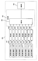
- the clamping pressure of the metal belt 510 is set as one of the parameters representing the state of the continuously variable transmission 500. As shown in FIG. 3, the clamping pressure is set for each of the plurality of control modes A to H. The clamping pressure is adjusted according to the driving state of the vehicle so that the metal belt 510 does not slip.
- the clamping pressure is increased or decreased according to the braking force.
- the hydraulic pressure supplied to the secondary pulley 508 is increased compared to when the brake pedal is not depressed. Thereby, the slip of the metal belt 510 during braking can be prevented.
- control mode described above is an example.
- the method for setting the clamping pressure in each control mode may be performed by using a well-known general technique, and therefore, detailed description thereof will not be repeated here.
- the number of control modes may be any number.
- the type of control mode is arbitrarily determined by the developer.
- Each control mode may be configured by software, may be configured by hardware, or may be configured by a combination of software and hardware.
- control modes A to H are not executed alternatively but can be executed simultaneously. That is, the clamping pressure can be set at the same time in a plurality of control modes.
- the clamping pressure set in each control mode is also referred to as the first set value.
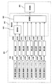
- the first set value is set for each of a plurality of control modes A to H by the setting units 930A to H of ECU 900.
- the first set value represents the target value of the clamping pressure of the metal belt 510 in the stable state.
- the clamping pressure of the metal belt 510 is finally controlled to be the same as the first set value.
- ECU 900 includes a plurality of calculation units 940A to 940H provided for each of a plurality of control modes A to H.
- the calculation units 940A to 940H calculate, for each control mode, a second setting value that changes later than the first setting value from the first setting value set in each control mode.
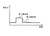
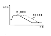
- the second set value that is delayed with respect to the first set value is calculated. That is, only when the first set value decreases, the second set value changes with a delay compared to the first set value. Therefore, when the first set value increases or is constant, the first set value and the second set value are the same.
- the second set value decreases with a delay compared to the first set value.
- the second set value may be calculated so as to increase with a delay compared to the first set value.
- the condition for calculating the second set value that is, a specific method for calculating the second set value is predetermined for each control mode by the developer. Therefore, the decreasing speed of the second set value is determined for each control mode.
- the second set value calculated in the control mode A starts to decrease simultaneously or substantially simultaneously with the first set value. Further, the second set value is calculated so that the rate of decrease gradually decreases. As illustrated in FIG. 5, the second set value calculated in the control mode B starts to decrease with a delay compared to the first set value.
- the decrease rate of the second set value is the same as or substantially the same as the decrease rate of the first set value.
- the second set value described above is an example. The method for calculating the second set value is not limited to these.
- the second set value may be calculated as a first-order lag response to the first set value.
- the calculation units 940A to 940H may be configured by software, may be configured by hardware, or may be configured by a combination of software and hardware.
- the target value finally used for controlling the clamping pressure is set in consideration of a plurality of second set values.
- the setting unit 942 of the ECU 900 sets a target value for the pinching pressure of the metal belt 510 so as to be equal to or greater than the maximum second set value among the plurality of second set values.
- the target value is set so as to be the sum of a plurality of second setting values. More specifically, the target value is set so as to be the sum of the maximum second setting value of some second setting values and the other second setting values.
- the selection unit 944 selects the larger second setting value of the second setting value of the control mode A and the second setting value of the control mode B.
- the adding unit 946 the sum of the selected second set value and the second set values of the other control modes C to H is calculated as a target value.
- the target value setting method is not limited to these.
- the maximum second setting value may be selected from the second setting values in three or more arbitrary control modes. As illustrated in FIG. 6, the target value may be set so as to be the sum of a plurality of second setting values without selecting the largest second setting value among some of the second setting values. . As illustrated in FIG. 7, the target value may be set so as to be the maximum second setting value among the plurality of second setting values.
- the setting unit 942, the selection unit 944, and the addition unit 946 may be configured by software, may be configured by hardware, or may be configured by a combination of software and hardware.
- control unit 948 of the ECU 900 controls the continuously variable transmission 500 so that the clamping pressure of the metal belt 510 becomes the set target value.
- the control unit 948 may be configured by software, may be configured by hardware, or may be configured by a combination of software and hardware.
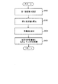
- step (hereinafter, step is abbreviated as S) 100 ECU 900 sets a first set value of the clamping pressure of metal belt 510 for each of a plurality of control modes.
- ECU 900 calculates a second set value that changes later than the first set value from the first set value for each of the plurality of control modes.
- ECU 900 sets the target value of the clamping pressure so as to be equal to or greater than the maximum second set value among the plurality of second set values.
- ECU 900 controls continuously variable transmission 500 so that the clamping pressure of metal belt 510 becomes a target value.
- the target value can be set in consideration of the conditions determined for each of the plurality of control modes. Therefore, the clamping pressure of the metal belt 510 can be controlled based on a plurality of conditions determined in a plurality of control modes.
- the clamping pressure of the metal belt 510 is increased to a pressure determined in consideration of a high braking force.
- the clamping pressure is gradually reduced at the speed determined in the control mode B until the second set value in the control mode B becomes the same as the second set value in the control mode A at time T3. .
- the clamping pressure is gradually reduced at a speed determined in the control mode A to a pressure determined in consideration of an input torque lower than the input torque before the brake pedal is depressed.
- the continuously variable transmission 500 can be controlled so as to satisfy the conditions required for each of the plurality of control modes while the clamping force of the metal belt 510 is changed. Therefore, it is possible to suitably control the clamping pressure.
- the parameter indicating the state of continuously variable transmission 500 is not limited to the clamping pressure of metal belt 510.
- the present invention may be applied to the input shaft rotation speed, the gear ratio, the engine rotation speed, the output torque of the engine 200, and the like of the continuously variable transmission 500.
- the first set value set for each of the plurality of control modes is delayed from the first set value.
- a second set value that changes in this manner is calculated.
- the sum of the first set values is constant, the actual clamping pressure cannot undershoot or the like with respect to the target value.
- the second set value is invalidated.
- the invalidation of the second set value is achieved by limiting the target value below the sum of the plurality of first set values while the sum of the plurality of first set values set in the plurality of control modes is constant. Is done.
- ECU 900 The function of ECU 900 will be described with reference to FIG. 11 and FIG. Note that the same functions as those in the first embodiment are denoted by the same reference numerals. Therefore, detailed description thereof will not be repeated here.
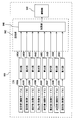
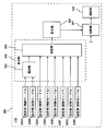
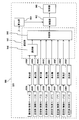
- the calculation unit 950 of the ECU 900 calculates the sum of the plurality of first set values calculated for each of the plurality of control modes. For example, the sum of the maximum first setting value among some first setting values and the other first setting values is calculated.
- the selection unit 952 selects the larger first setting value of the first setting value of the control mode A and the first setting value of the control mode B.
- the adder 954 calculates the sum of the selected first set value and the first set values of the other control modes C to H.
- the maximum first setting value may be selected from the first setting values in three or more arbitrary control modes.
- the sum of a plurality of second setting values may be calculated without selecting the maximum first setting value.
- the calculation unit 950, the selection unit 952, and the addition unit 954 may be configured by software, may be configured by hardware, or may be configured by a combination of software and hardware.
- the calculation unit 960 of the ECU 900 calculates a fourth set value that changes later than the sum of the plurality of first set values from the sum of the plurality of first set values.
- the fourth set value is calculated in the same manner as the second set value with the slowest change speed among the second set values calculated for each of the plurality of control modes A to H. Therefore, if the change speed of the second set value calculated in the control mode A is the slowest, as shown in FIG. 13, it decreases at the same speed as the second set value calculated in the control mode A.
- the fourth set value is calculated.
- the restriction unit 962 of the ECU 900 restricts the target value to be equal to or lower than the fourth set value. Specifically, the sum of the plurality of second setting values (the sum of the maximum second setting value of some second setting values and the other second setting values) and the fourth setting value The smaller one is output as the target value.
- the fourth set value is calculated so as to decrease later than the sum of the plurality of first set values. That is, the fourth set value changes later than the sum of the plurality of first set values only when the sum of the plurality of first set values decreases. Therefore, while the sum of the plurality of first setting values set in the plurality of control modes is constant, the fourth setting value is the same as the sum of the plurality of first setting values.
- the second set value is calculated so as to decrease later than the first set value. For this reason, if the first setting value set in the control mode D increases by the amount that the first setting value set in the control mode C decreases, the second setting is set even if the sum of the first setting values is constant. The sum of the values is larger than the sum of the first set values.
- the target value is limited to the sum of the plurality of first set values.
- ECU 900 calculates the sum of a plurality of first set values. More specifically, the sum of the maximum first setting value among some first setting values and the other first setting values is calculated.
- ECU 900 calculates a fourth set value that changes with a delay compared to the sum of the plurality of first set values.
- ECU 900 limits the target value to the fourth set value or less. In this way, it is possible to prevent an unnecessary increase in the clamping pressure.
Landscapes
- Engineering & Computer Science (AREA)
- General Engineering & Computer Science (AREA)
- Mechanical Engineering (AREA)
- Control Of Transmission Device (AREA)
Abstract
Description
図1を参照して、車両に搭載されたパワートレーン100のエンジン200の出力は、トルクコンバータ300を介して、前後進切換装置400を有する無段変速機500に入力される。無段変速機500の出力は、減速歯車600および差動歯車装置700に伝達され、左右の駆動輪800へ分配される。パワートレーン100は、後述するECU(Electronic Control Unit)900により制御される。なお、エンジン200の代わりにもしくは加えて、モータを駆動源として用いるようにしてもよい。無段変速機500の代わりに多段自動変速機を用いるようにしてもよい。
ステップ(以下、ステップをSと略す)100にて、ECU900は、複数の制御モード毎に、金属ベルト510の挟圧力の第1設定値を設定する。
S106にて、ECU900は、金属ベルト510の挟圧力が目標値になるように、無段変速機500を制御する。
[第2の実施の形態]
以下、第2の実施の形態について説明する。上述したように、第1の実施の形態においては、実際の挟圧力のアンダーシュートを防止するために、複数の制御モード毎に設定された第1設定値から、第1設定値に比べて遅れて変化する第2設定値が算出される。一方、図10に示すように、第1設定値の和が一定である間は、目標値に対して実際の挟圧力がアンダーシュート等し得ない。したがって、低下する前後の第1設定値を滑らかに繋ぐための処理、すなわち第2設定値の算出は必要ない。そこで、本実施の形態においては、第2設定値が無効にされる。第2設定値の無効化は、複数の制御モードにおいて設定された複数の第1設定値の和が一定である間、複数の第1設定値の和以下に目標値が制限されることによって達成される。
このようにすれば、挟圧力の無駄な増大を防ぐことができる。
Claims (10)
- 機器と、
前記機器を制御するための制御装置とを備えた車両であって、
前記制御装置は、
複数の制御モード毎に、前記機器の状態を表わすパラメータの第1の値を設定し、
前記複数の制御モード毎に、前記第1の値に比べて遅れて変化する第2の値を前記第1の値から算出し、
複数の前記第2の値のうちの最大の第2の値以上になるように、前記パラメータの目標値を設定し、
前記パラメータが前記目標値になるように前記機器を制御する、車両。 - 前記第2の値は、前記第1の値に比べて遅れて低下するように算出される、請求の範囲1に記載の車両。
- 前記制御装置は、複数の前記第1の値の和が一定である間、複数の前記第1の値の和以下に前記目標値を制限する、請求の範囲1に記載の車両。
- 前記制御装置は、
複数の前記第1の値の和に比べて遅れて変化する第4の値を複数の前記第1の値の和から算出し、
前記第4の値以下に前記目標値を制限する、請求の範囲1に記載の車両。 - 前記制御装置は、複数の前記第2の値の和になるように、前記目標値を設定する、請求の範囲1に記載の車両。
- 前記制御装置は、一部の第2の値のうちの最大の第2の値と、他の第2の値との和になるように、目標値を設定する、請求の範囲1に記載の車両。
- 前記制御装置は、複数の前記第2の値のうちの最大の第2の値になるように、前記目標値を設定する、請求の範囲1に記載の車両。
- 前記機器は、一対のプーリと、前記一対のプーリとの間でトルクを伝達するベルトおよびチェーンのうちのいずれか一方とを含む無段変速機であって、
前記パラメータは、前記ベルトおよび前記チェーンのうちのいずれか一方を前記プーリが挟持する圧力である、請求の範囲1に記載の車両。 - 機器の制御装置であって、
複数の制御モード毎に、前記機器の状態を表わすパラメータの第1の値を設定するための設定手段と、
前記複数の制御モード毎に、前記第1の値に比べて遅れて変化する第2の値を前記第1の値から算出するための算出手段と、
複数の前記第2の値のうちの最大の第2の値以上になるように、前記パラメータの目標値を設定するための設定手段と、
前記パラメータが前記目標値になるように前記機器を制御するための制御手段とを備える、機器の制御装置。 - 機器の制御方法であって、
複数の制御モード毎に、前記機器の状態を表わすパラメータの第1の値を設定するステップと、
前記複数の制御モード毎に、前記第1の値に比べて遅れて変化する第2の値を前記第1の値から算出するステップと、
複数の前記第2の値のうちの最大の第2の値以上になるように、目標値を設定するステップと、
前記パラメータが前記目標値になるように前記機器を制御するステップとを備える、機器の制御方法。
Priority Applications (3)
| Application Number | Priority Date | Filing Date | Title |
|---|---|---|---|
| JP2012517006A JP5333667B2 (ja) | 2010-05-24 | 2010-05-24 | 車両、無段変速機の制御装置および制御方法 |
| PCT/JP2010/058714 WO2011148451A1 (ja) | 2010-05-24 | 2010-05-24 | 車両、機器の制御装置および制御方法 |
| US13/634,857 US8977451B2 (en) | 2010-05-24 | 2010-05-24 | Vehicle, control apparatus and control method for equipment |
Applications Claiming Priority (1)
| Application Number | Priority Date | Filing Date | Title |
|---|---|---|---|
| PCT/JP2010/058714 WO2011148451A1 (ja) | 2010-05-24 | 2010-05-24 | 車両、機器の制御装置および制御方法 |
Publications (1)
| Publication Number | Publication Date |
|---|---|
| WO2011148451A1 true WO2011148451A1 (ja) | 2011-12-01 |
Family
ID=45003460
Family Applications (1)
| Application Number | Title | Priority Date | Filing Date |
|---|---|---|---|
| PCT/JP2010/058714 Ceased WO2011148451A1 (ja) | 2010-05-24 | 2010-05-24 | 車両、機器の制御装置および制御方法 |
Country Status (3)
| Country | Link |
|---|---|
| US (1) | US8977451B2 (ja) |
| JP (1) | JP5333667B2 (ja) |
| WO (1) | WO2011148451A1 (ja) |
Cited By (1)
| Publication number | Priority date | Publication date | Assignee | Title |
|---|---|---|---|---|
| JP2014132165A (ja) * | 2013-01-07 | 2014-07-17 | Fuji Heavy Ind Ltd | パワーユニットの制御装置 |
Citations (5)
| Publication number | Priority date | Publication date | Assignee | Title |
|---|---|---|---|---|
| JPH07217713A (ja) * | 1994-01-31 | 1995-08-15 | Nissan Motor Co Ltd | 無段変速機の制御装置 |
| JPH1182707A (ja) * | 1997-08-29 | 1999-03-26 | Honda Motor Co Ltd | 車両用無段変速機の制御装置 |
| JP2004316717A (ja) * | 2003-04-14 | 2004-11-11 | Toyota Motor Corp | 制動によりダウンシフトと挾持圧増大を行う車輌用変速装置 |
| JP2007120733A (ja) * | 2005-10-31 | 2007-05-17 | Jatco Ltd | 自動車用無段変速機の制御装置 |
| JP2008020055A (ja) * | 2006-06-15 | 2008-01-31 | Toyota Motor Corp | ベルト式無段変速機の制御装置 |
Family Cites Families (6)
| Publication number | Priority date | Publication date | Assignee | Title |
|---|---|---|---|---|
| JP4396247B2 (ja) | 2003-12-03 | 2010-01-13 | トヨタ自動車株式会社 | ベルト式無段変速機の油圧制御装置 |
| JP4811211B2 (ja) | 2006-03-22 | 2011-11-09 | トヨタ自動車株式会社 | 車両用自動変速機の制御装置 |
| JP4690255B2 (ja) * | 2006-06-15 | 2011-06-01 | トヨタ自動車株式会社 | ベルト式無段変速機の制御装置 |
| JP4893134B2 (ja) | 2006-07-19 | 2012-03-07 | トヨタ自動車株式会社 | 車両用無段変速機の制御装置 |
| JP4762875B2 (ja) * | 2006-12-15 | 2011-08-31 | ジヤトコ株式会社 | ベルト式無段変速機の変速制御装置 |
| JP2009074668A (ja) * | 2007-09-25 | 2009-04-09 | Jatco Ltd | ベルト式無段変速機のライン圧制御装置 |
-
2010
- 2010-05-24 US US13/634,857 patent/US8977451B2/en not_active Expired - Fee Related
- 2010-05-24 JP JP2012517006A patent/JP5333667B2/ja not_active Expired - Fee Related
- 2010-05-24 WO PCT/JP2010/058714 patent/WO2011148451A1/ja not_active Ceased
Patent Citations (5)
| Publication number | Priority date | Publication date | Assignee | Title |
|---|---|---|---|---|
| JPH07217713A (ja) * | 1994-01-31 | 1995-08-15 | Nissan Motor Co Ltd | 無段変速機の制御装置 |
| JPH1182707A (ja) * | 1997-08-29 | 1999-03-26 | Honda Motor Co Ltd | 車両用無段変速機の制御装置 |
| JP2004316717A (ja) * | 2003-04-14 | 2004-11-11 | Toyota Motor Corp | 制動によりダウンシフトと挾持圧増大を行う車輌用変速装置 |
| JP2007120733A (ja) * | 2005-10-31 | 2007-05-17 | Jatco Ltd | 自動車用無段変速機の制御装置 |
| JP2008020055A (ja) * | 2006-06-15 | 2008-01-31 | Toyota Motor Corp | ベルト式無段変速機の制御装置 |
Cited By (1)
| Publication number | Priority date | Publication date | Assignee | Title |
|---|---|---|---|---|
| JP2014132165A (ja) * | 2013-01-07 | 2014-07-17 | Fuji Heavy Ind Ltd | パワーユニットの制御装置 |
Also Published As
| Publication number | Publication date |
|---|---|
| US8977451B2 (en) | 2015-03-10 |
| US20130013162A1 (en) | 2013-01-10 |
| JPWO2011148451A1 (ja) | 2013-07-25 |
| JP5333667B2 (ja) | 2013-11-06 |
Similar Documents
| Publication | Publication Date | Title |
|---|---|---|
| JP4363486B2 (ja) | 無段変速機の制御装置および制御方法 | |
| KR101967570B1 (ko) | 차량용 무단 변속기의 제어 장치 | |
| EP2074340B1 (en) | Apparatus and method for controlling continuously variable transmission and program for performing the control method | |
| WO2009128304A1 (ja) | 無段変速機の制御装置および制御方法 | |
| JP5850062B2 (ja) | 車両用無段変速機の制御装置 | |
| JP2015058897A (ja) | 車両用無段変速機の変速制御装置 | |
| JP2014114937A (ja) | 無段変速機の変速制御装置 | |
| JP2010196881A (ja) | 車両の制御装置 | |
| JP2014137105A (ja) | 車両用無段変速機の変速制御装置 | |
| JP5447274B2 (ja) | 車両用無段変速機の制御装置 | |
| JP5333667B2 (ja) | 車両、無段変速機の制御装置および制御方法 | |
| JP6110677B2 (ja) | 無段変速機の変速制御装置 | |
| JP2012072801A (ja) | 車両用無段変速機の変速制御装置 | |
| CN100453855C (zh) | 自动变速器的液压控制装置 | |
| JP2010261518A (ja) | ベルト式無段変速機を備えた車両の制御装置 | |
| JP5673324B2 (ja) | 車両用無段変速機の変速制御装置 | |
| JP5500243B2 (ja) | 車両、変速機の制御方法および制御装置 | |
| JP2006046354A (ja) | 車両の制御装置 | |
| JP2011106615A (ja) | 無段変速機の制御装置 | |
| JP5186938B2 (ja) | 無段変速機の制御装置 | |
| JP2009047269A (ja) | 車両用無段変速機の変速制御装置 | |
| JP2005350017A (ja) | 車両の制御装置 | |
| JP2010265918A (ja) | 無段変速機の制御装置および制御方法 | |
| JP4496854B2 (ja) | 無段変速機の制御装置 | |
| JP2018155331A (ja) | 無段変速機の制御装置 |
Legal Events
| Date | Code | Title | Description |
|---|---|---|---|
| WWE | Wipo information: entry into national phase |
Ref document number: 2012517006 Country of ref document: JP |
|
| 121 | Ep: the epo has been informed by wipo that ep was designated in this application |
Ref document number: 10852122 Country of ref document: EP Kind code of ref document: A1 |
|
| WWE | Wipo information: entry into national phase |
Ref document number: 13634857 Country of ref document: US |
|
| NENP | Non-entry into the national phase |
Ref country code: DE |
|
| 122 | Ep: pct application non-entry in european phase |
Ref document number: 10852122 Country of ref document: EP Kind code of ref document: A1 |