WO2011145596A1 - 自動製パン器 - Google Patents
自動製パン器 Download PDFInfo
- Publication number
- WO2011145596A1 WO2011145596A1 PCT/JP2011/061273 JP2011061273W WO2011145596A1 WO 2011145596 A1 WO2011145596 A1 WO 2011145596A1 JP 2011061273 W JP2011061273 W JP 2011061273W WO 2011145596 A1 WO2011145596 A1 WO 2011145596A1
- Authority
- WO
- WIPO (PCT)
- Prior art keywords
- bread
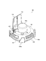
- container
- bread container
- blade
- main body
- Prior art date
- Legal status (The legal status is an assumption and is not a legal conclusion. Google has not performed a legal analysis and makes no representation as to the accuracy of the status listed.)
- Ceased
Links
Images












Classifications
-
- A—HUMAN NECESSITIES
- A21—BAKING; EDIBLE DOUGHS
- A21B—BAKERS' OVENS; MACHINES OR EQUIPMENT FOR BAKING
- A21B7/00—Baking plants
- A21B7/005—Baking plants in combination with mixing or kneading devices
Definitions
- the present invention relates to an automatic bread maker mainly used in general households.
- an automatic bread maker for home use generally has a mechanism for producing bread by directly using a bread container into which bread ingredients are placed (see, for example, Patent Document 1).
- a bread container in which bread ingredients are placed is placed in a baking chamber in the main body.
- the bread raw material in a bread container is kneaded into bread dough with the kneading blade provided in a bread container (kneading process).
- a fermentation process for fermenting the kneaded bread dough is performed, and the bread container is used as a baking mold to bake the bread (baking process).
- some conventional home-made bread maker is provided with a material container so that bread containing raisins, nuts, cheese, etc. can be baked (see, for example, Patent Documents 2 and 3). ).
- the ingredients contained in the ingredient container during the kneading process are automatically charged into the bread container, for example, by program control.
- this bread manufacturing method first, cereal grains and liquid are mixed, and the crushed blade is rotated in this mixture to pulverize the cereal grains (grinding step). And the bread raw material containing the paste-form ground powder obtained through the grinding process is kneaded into bread dough using a kneading blade (kneading process). Thereafter, a fermentation process for fermenting the kneaded bread dough is performed, followed by a baking process for baking the bread.
- JP 2000-116526 A Japanese Patent No. 3191645 JP 2006-255071 A JP 2010-35476 A
- the present applicants are working on the development of an automatic bread maker equipped with a new mechanism capable of executing the above-described method for producing bread using cereal grains as a starting material. Among them, the present applicants are studying the development of an automatic bread maker that can easily perform conventional bread production using commercially available wheat flour or rice flour.
- the present applicants can execute the baking process from the above-described crushing process in a bread container accommodated in a baking chamber provided in the main body, for example, as a configuration of an automatic bread maker having this new mechanism. Think of a configuration.
- the present applicants consider a configuration in which the crushing function and the kneading function are appropriately exhibited by the rotation of one rotating shaft (blade rotating shaft) disposed at the bottom of the bread container. Yes.
- a coupling for transmitting the rotation of the motor (provided in the main body) to the blade rotation shaft is required.
- This coupling includes, for example, a main body side connecting portion provided at the upper end of a driving shaft (a rotating shaft disposed in the main body and rotating by driving a motor in the main body), and a container provided at the lower end of the blade rotating shaft. And a side connection portion.
- the automatic bread maker adopting the above-described coupling has the following problems. That is, in the pulverization process for pulverizing grain grains and the kneading process for kneading bread dough, force is easily applied to the bread container housed in the baking chamber. As a result, there is a problem that the bread container is lifted from the predetermined set position, and the power transmission by the coupling becomes unstable.
- the applicant of the present invention has obtained the blade rotation shaft when obtaining the pulverization function and when obtaining the kneading function. It is considered to adopt a configuration in which the rotation directions are opposite to each other. In this case, even if the above-described bayonet coupling is employed, in either case of the grinding process and the kneading process, the bread container moves (floats) and the power transmission by the coupling becomes unstable. Will occur.
- the orientation (accommodating direction) of the bread container when the bread container is stored (set) in the baking chamber is determined. It is often done. For this reason, if a bread container can be easily set in a baking chamber according to this accommodation direction, the automatic bread maker will be convenient for the user, which is preferable.
- This problem is not limited to an automatic bread maker that can bake bread using cereal grains as a starting material, but also to a conventional automatic bread maker that bakes bread using cereal flour (such as wheat flour or rice flour) as a starting material. This is also true.
- the present invention has been made in view of the above points, and uses a bread container capable of breadmaking using grain grains as a starting material and a bread container capable of breadmaking using commercially available grain flour as a starting material. And it aims at providing the automatic bread maker which can store these two types of bread containers compactly.
- Another object of the present invention is to provide an automatic bread maker having a convenient mechanism for baking bread from cereal grains, which can easily place a bread container at a set position in the main body. And The present invention also provides an automatic bread maker having a convenient mechanism for baking bread from grains, wherein the bread container can be easily placed at a set position in the main body, and the bread container accommodated in the main body is Another object is to provide an automatic bread maker that does not move easily during the manufacturing process.
- an automatic bread maker of the present invention includes a first bread container capable of making bread using cereal grains as a starting material and a second bread container capable of making bread using cereal flour as a starting material.
- a first bread container capable of making bread using cereal grains as a starting material
- a second bread container capable of making bread using cereal flour as a starting material.
- either one of the first bread container and the second bread container is selectively stored, and in the storage, the first bread And an accommodating portion that can be accommodated in a state where either one of the container and the second bread container is accommodated in the other.
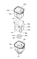
- the inner bread container is disposed on the inner bottom surface of the outer bread container. It is preferable that the first cushioning material that receives the outer bottom surface of the inner bread container is disposed, and the second cushioning material that wraps the outer circumferential surface of the inner bread container is disposed on the inner circumferential surface of the outer bread container. .
- the outer bread container is the first bread container in which a recess is formed at the bottom, and the first cushioning material is inserted into the recess when stored. It is preferable to adopt a configuration.
- the first cushioning material is made of polystyrene foam and the second cushioning material is made of cardboard paper.
- a first bread container capable of bread and a second bread container capable of bread making using grain flour as a starting material can be used properly. And when putting out the automatic bread maker after bread making, either one of the first bread container and the second bread container is put in the other, and both bread containers are in the main body. Since it can be accommodated in the baking chamber, there are no problems with storage even though there are two types of bread containers.
- a bread container side guide portion is provided on an outer surface of the first bread container, and the first bread container is provided on the inner surface of the housing portion.
- a main body side guide portion that engages with the bread container side guide portion and guides the bread container to a set position when the bread container side guide portion is in the vicinity of the upper end portion of the housing portion when being accommodated. It is preferable to adopt a configuration in which
- the first bread container when the first bread container is disposed at the set position in the housing portion, the first bread container is guided by the guide portion (two of the bread container side guide portion and the main body side guide portion). It reaches the set position. For this reason, it is easy to set the first bread container in the accommodating portion. Further, when the first bread container is received in the baking chamber, the main body side guide part is engaged with the bread container side guide part when the bread container side guide part is in the vicinity of the upper end part of the housing part. ing. For this reason, the user can implement
- a pedestal is provided at the bottom of the outer surface of the first bread container, and a bread container support part for receiving the pedestal is provided at the bottom of the housing part, and the main body side guide
- the portion is provided so that the pedestal does not reach the bread container support part when the bread container side guide part starts to engage with the main body side guide part.
- the first bread container can be accommodated in the accommodating portion by appropriately positioning the pedestal and the bread container supporting portion by the main body side guide portion and the bread container side guide portion. That is, it is possible to avoid a situation in which the pedestal is caught by any part of the storage unit and cannot move during the storage of the first bread container in the storage unit. For this reason, the user can easily set the first bread container in the accommodating portion.
- the bread container side guide portion and the main body side guide portion cooperate to form the first bread container. It is preferable to adopt a configuration that exhibits the function of fixing the container. According to this structure, it can prevent that a 1st bread container moves within a accommodating part during execution of the manufacturing process of a bread. For this reason, according to this structure, bread can be manufactured stably.
- a rotary shaft provided at the bottom of the first bread container, a crushing blade and a kneading blade that can be rotated by rotation of the rotary shaft, and a main body having the housing portion are provided.
- the pulverization function by the pulverization blade is obtained, and the kneading function by the kneading blade is obtained when the rotating shaft is rotated in the direction opposite to the one direction by the motor.
- a flange is formed on the opening side edge of the first bread container, and a handle member is attached to the flange so as to be able to stand upside down. It is good also as a structure which a part of the said handle member contact
- the bread container side guide portion has an engagement groove extending in a direction in which the first bread container is received in the storage portion, and the main body side guide portion is formed of the storage portion. It is good also as a structure which has an engaging protrusion part which protrudes from an inner surface and engages with the said engaging groove. According to this configuration, it is easy to obtain a configuration in which the guide portion exhibits two functions such as guiding the first bread container and fixing the first bread container.
- the main body side guide portion includes a plate-like fixing portion attached to the inner surface of the housing portion, and a protruding piece portion that is folded back with respect to the fixing portion.
- the protruding piece portion may be the engaging protruding portion.
- the protruding piece portion may be provided with a bent portion that increases an inclination angle with respect to the fixed portion.
- the projecting piece portion has a smaller inclination angle of the projecting piece portion with respect to the fixed portion on the front side in the receiving direction when the first bread container is received in the storage portion, and the first bread container is It is preferable that the protrusion is bent so that the inclination angle of the protruding portion with respect to the fixed portion is increased from the position before reaching the set position. With such a configuration, the first bread container can be smoothly accommodated in the accommodating portion, and the force for fixing the first bread container when the first bread container reaches the set position. Is sufficiently obtained.
- the engagement groove preferably extends to the vicinity of the upper end of the first bread container. According to this configuration, since the engagement range of the engagement groove and the engagement protrusion can be widened, the first bread container can be stably guided using the bread container side guide part and the main body side guide part. .
- a bread container capable of making bread using cereal grains as a starting material and a bread container capable of making bread using commercially available cereal flour as a starting material can be used separately.
- An automatic bread machine that can be stored compactly can be provided.
- an automatic bread maker having a convenient mechanism for baking bread from grain grains the bread container can be easily placed in a set position in the main body, and the bread container accommodated in the main body is a bread It is possible to provide an automatic bread maker that is difficult to move during the manufacturing process.
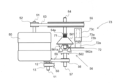
- the figure for demonstrating the clutch contained in the 1st power transmission part with which the automatic bread maker of this embodiment is provided, and the figure which shows the state in which a clutch cuts off power
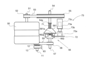
- the figure for demonstrating the clutch contained in the 1st power transmission part with which the automatic bread maker of this embodiment is provided, and the figure which shows the state in which a clutch transmits power
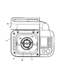
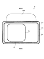
- Schematic plan view when the automatic bread maker (the lid is open) of this embodiment is viewed from above
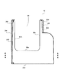
- the schematic side view which shows the structure of the main body side guide part provided in the baking chamber of the automatic bread maker of this embodiment.
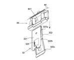
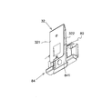
- the schematic perspective view at the time of seeing the main body side guide part provided in the baking chamber of the automatic bread maker of this embodiment from diagonally above The schematic perspective view at the time of seeing the main body side guide part provided in the baking chamber of the automatic bread maker of this embodiment from diagonally below
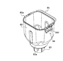
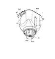
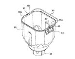
- the schematic perspective view at the time of seeing the bread container with which the automatic bread maker of this embodiment is provided from diagonally upward The schematic perspective view at the time of seeing the bread container with which the automatic bread maker of this embodiment is provided from diagonally downward
- Figure showing the state before In the case where the bread container is accommodated in the baking chamber it is a schematic diagram for explaining the relationship between the main body side guide part and the bread container side guide part, and the main body side guide part and the bread container side guide part are engaged with each other FIG.
- FIG. 2 is a diagram showing a state before the bread container reaches the set position of the baking chamber.
- FIG. 2 is a schematic diagram for explaining the relationship between the main body side guide part and the bread container side guide part, and the main body side guide part and the bread container side guide part are engaged with each other
- FIG. 2 is a view showing a state where the bread container has reached the set position of the baking chamber.
- the schematic perspective view which shows the structure of the blade unit with which the automatic bread maker of this embodiment is provided.
- Schematic exploded perspective view showing a configuration of a blade unit provided in the automatic bread maker of the present embodiment The schematic side view which shows the structure of the blade unit with which the automatic bread maker of this embodiment is provided.
- 11A is a schematic cross-sectional view at the AA position in FIG.
- position The bottom view of the blade unit with which the automatic bread maker of this embodiment is provided, and the figure which shows the state where the kneading blade was in the open posture.
- the top view of the bread container with which the automatic bread maker of this embodiment is equipped, The figure which shows the state which the kneading
- the top view of the bread container with which the automatic bread maker of this embodiment is provided, and the figure which shows the state which the kneading blade was in the open attitude
- the schematic perspective view which shows the structure of the bread raw material storage container with which the automatic bread maker of this embodiment is provided, The figure which mainly shows the front side
- FIG. 18B is a schematic cross-sectional view at the BB position.
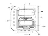
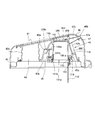
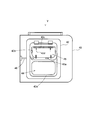
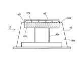
- FIG. 20 is a schematic plan view for explaining the relationship between a frame member and a duct included in the automatic bread maker of the present embodiment, and is a view when viewed along an arrow Y in FIG. 20. It is a schematic plan view for demonstrating the relationship between the frame member with which the automatic bread maker of this embodiment is equipped, and a duct, and the figure at the time of seeing along the arrow Z of FIG.
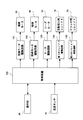
- FIG. 21A Block diagram of the automatic bread maker of this embodiment Time chart of bread making course for rice grain executed by automatic bread maker of this embodiment It is explanatory drawing similar to FIG. 4, Comprising: The figure which shows the state by which the 2nd bread container was stored in the 1st bread container The exploded perspective view of the 1st bread container, the 2nd bread container, the 1st shock absorbing material, and the 2nd shock absorbing material Sectional drawing at the time of cutting a main body in the vertical direction with the schematic diagram for demonstrating the modification of the main body structure of the automatic bread maker which concerns on this embodiment A schematic diagram for explaining a modification of the main body structure of the automatic bread maker according to the present embodiment, a cross-sectional view when the main body is cut in the horizontal direction It is a figure which shows the modification of the bread container with which the automatic bread maker of this embodiment is provided, and is a schematic perspective view at the time of seeing from diagonally upward It is a figure which shows the modification of the bread container with which the automatic bread maker of this embodiment is provided, and is
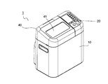
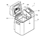
- FIGS. 1A and 1B are schematic perspective views showing an external configuration of the automatic bread maker according to the present embodiment.
- FIG. 1A is a view showing a state where the lid is opened
- FIG. 1B is a view showing a state where the lid is closed.
- a part of the upper surface of the main body 10 (the outer shell of which is formed of, for example, metal or synthetic resin) of the automatic bread maker 1 provided in a substantially rectangular parallelepiped shape has an operation unit 20 is provided.
- the operation unit 20 includes an operation key group, and a display unit that displays time, contents set by the operation key group, errors, and the like.
- the operation key group includes, for example, a start key, a cancel key, a timer key, a reservation key, a bread manufacturing course (a course for manufacturing bread using rice grains as a starting material, a course for manufacturing bread using rice flour as a starting material) And a selection key for selecting a course for producing bread using wheat flour as a starting material.
- the display unit is configured by, for example, a liquid crystal display panel.
- the baking chamber 30 in which the bread container 80 and the bread container 120 are selectively attached serves as a storage unit.
- the firing chamber 30 is a substantially rectangular box-shaped chamber composed of a bottom wall 30a made of, for example, sheet metal and four side walls 30b (see also FIG. 4 described later), and an upper surface thereof is open.
- the upper surface opening of the baking chamber 30 is closed by a lid 40 provided at the upper part of the main body 10.
- the lid 40 is attached to the back side of the main body 10 with a hinge shaft (not shown), and rotates with the hinge shaft as a fulcrum.
- the lid 40 is provided with a viewing window 41 made of heat-resistant glass, for example, so that the inside of the baking chamber 30 can be seen.
- a bread raw material storage container 110 is detachably attached to the lid 40.
- the bread ingredient storage container 110 enables a part of bread ingredients to be automatically charged during the bread manufacturing process.
- FIG. 1B shows a state where the bread ingredient storage container 110 is attached to the lid 40.
- the lid 40 has an inclined structure in which substantially the entire upper surface rises from the front side to the back side of the main body 10 in the closed state. For this reason, it is easy to observe the inside of the bread container 80 accommodated in the baking chamber 30 from the viewing window 10 disposed near the front surface of the main body 10 in a state where the lid 40 is closed. In addition, in the state where the lid 40 is closed, the bread ingredient storage container 110 attached to the back side of the main body 10 is disposed in a portion where the thickness of the lid 40 is thick. You can earn volume.
- FIG. 2 is a schematic diagram for explaining the internal configuration of the main body of the automatic bread maker according to the present embodiment.
- FIG. 2 assumes a case where the automatic bread maker 1 is viewed from above, and the lower side of the figure is the front side of the automatic bread maker 1 and the upper side of the figure is the back side.
- a low-speed / high-torque type kneading motor 50 used in the kneading process is fixedly disposed on the right side of the baking chamber 30, and the grinding process is performed behind the baking chamber 30.
- the high-speed rotation type crushing motor 60 used in the above is fixedly arranged.
- the kneading motor 50 and the crushing motor 60 are both shafts.
- the first pulley 52 is fixed to the output shaft 51 protruding from the upper surface of the kneading motor 50.
- the first pulley 52 is connected by a first belt 53 to a second pulley 55 having a diameter larger than that of the first pulley 52 and fixed to the upper side of the first rotating shaft 54.
- a second rotation shaft 57 is disposed under the first rotation shaft 54 so that the rotation center thereof is aligned with the rotation center of the first rotation shaft 54 (see FIGS. 3A and 3B).
- the first rotating shaft 54 and the second rotating shaft 57 are rotatably supported inside the main body 10.
- a clutch 56 that performs power transmission and power interruption is provided (see FIGS. 3A and 3B). The configuration of the clutch 56 will be described later.
- a third pulley 58 is fixed to the lower side of the second rotating shaft 57 (see FIGS. 3A and 3B).
- the third pulley 58 is provided on the lower side of the firing chamber 30 by the second belt 59 and is fixed to the driving shaft 11 and has a first driving shaft pulley 12 (having substantially the same diameter as the third pulley 58). (See FIGS. 3A and 3B).
- the kneading motor 50 itself is of a low speed / high torque type, and the rotation of the first pulley 52 is decelerated by the second pulley 55 (for example, decelerated to a speed of 1/5). For this reason, when the kneading motor 50 is driven in a state where the clutch 56 transmits power, the driving shaft 11 rotates at a low speed (for example, about 180 rpm) and a high torque.
- the power transmission unit constituted by the first driving shaft pulley 12 may be expressed as a first power transmission unit PT1.
- a fourth pulley 62 is fixed to the output shaft 61 protruding from the lower surface of the grinding motor 60.
- the fourth pulley 62 is fixed by the third belt 63 below the second driving shaft pulley 13 (below the first driving shaft pulley 12; FIG. 3A and FIG. 3B).
- the second driving shaft pulley 13 has substantially the same diameter as the fourth pulley 62.
- a grinding motor 60 that can rotate at high speed is selected. Since the rotation of the fourth pulley 62 is maintained at substantially the same speed in the second driving shaft pulley 13, the driving shaft 11 rotates at a high speed (for example, 7000 to 8000 rpm) by the high speed rotation of the grinding motor 60. Do.
- the power transmission unit composed of the fourth pulley 62, the third belt 63, and the second driving shaft pulley 13 may be hereinafter referred to as a second power transmission unit PT2.
- the second power transmission unit PT2 has a configuration that does not have a clutch, and connects the output shaft 61 of the crushing motor 60 and the driving shaft 11 so that power can be transmitted constantly.
- 3A and 3B are views for explaining a clutch included in the first power transmission unit provided in the automatic bread maker of the present embodiment.
- 3A and 3B are assumed to be viewed along the direction of the arrow X in FIG.
- the clutch 56 includes a first clutch member 561 and a second clutch member 562.
- the clutch 56 transmits power.
- the clutch 56 cuts off the power. That is, the clutch 56 is a meshing clutch.
- each of the clutch members 561 and 562 has a circumferential direction (when the first clutch member 561 is looked up from below, and when the second clutch member 562 is looked down from above). ) Are provided with six claws 561a and 562a arranged at almost equal intervals. The number and shape of the claws 561a and 562a may be appropriately selected from a preferable number and a preferable shape.
- the first clutch member 561 is slidable in the axial direction (vertical direction in FIGS. 3A and 3B) with respect to the first rotating shaft 54 and is not relatively rotatable. It is attached.
- a spring 71 is loosely fitted on the upper side of the first clutch member 561 of the first rotating shaft 54.
- the spring 71 is disposed so as to be sandwiched between a stopper portion 54a provided on the first rotating shaft 54 and the first clutch member 561, and biases the first clutch member 561 downward.
- the second clutch member 562 is fixed to the upper end of the second rotating shaft 57.
- Switching between the power transmission state and the power cut-off state in the clutch 56 is performed using an arm portion 72 that can move between a lower position and an upper position. A part of the arm portion 72 is disposed below the first clutch member 561 and can come into contact with the outer peripheral side of the first clutch member 561.
- the driving of the arm portion 72 is performed using a clutch solenoid 73.
- the clutch solenoid 73 includes a permanent magnet 73a and is a so-called self-holding solenoid.
- the plunger 73 b of the clutch solenoid 73 is fixed to the plunger fixing attachment portion 72 a of the arm portion 72. For this reason, the arm part 72 moves according to the movement of the plunger 73b in which the amount of protrusion from the housing 73c varies due to the application of voltage.
- the first clutch member 561 moves downward while being pushed by the urging force of the spring 71.
- the first clutch member 561 and the second clutch member 562 are engaged with each other. That is, when the arm portion 72 is in the lower position, the clutch 56 transmits power.
- the automatic bread maker 1 includes the clutch 56 that performs power transmission and power interruption in the first power transmission unit PT1.
- the second power transmission unit PT2 is not provided with a clutch, for the following reason. That is, even if the kneading motor 50 is driven, the driving shaft 11 is only rotated at a low speed (for example, 180 rpm). For this reason, even if the rotational power for rotating the driving shaft 11 is transmitted to the output shaft of the crushing motor 60, a large load is not applied to the kneading motor 50. And the manufacturing cost of the automatic bread maker 1 is suppressed by adopting the structure in which the clutch is not provided in the second power transmission part PT2 in this way. However, it goes without saying that a configuration in which a clutch is provided in the second power transmission unit PT2 may be adopted.
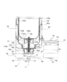
- FIG. 4 is a diagram schematically showing a configuration of a baking chamber in which a bread container is accommodated and its surroundings in the automatic bread maker of the present embodiment.
- FIG. 4 assumes a configuration when the automatic bread maker 1 is viewed from the front side, and the configurations of the baking chamber 30 and the bread container 80 are generally shown in cross-sectional views.
- FIG. 5 is a schematic plan view of the automatic bread maker (with the lid open) of this embodiment as viewed from above.
- FIG. 5 shows a state in which the bread container 80 is taken out from the baking chamber 30.
- the bread container 80 used as a baking mold while the bread raw material is input can be taken in and out of the baking chamber 30.
- a sheathed heater 31 (an example of a heating unit) is disposed inside the baking chamber 30 so as to surround the bread container 80 accommodated in the baking chamber 30. By energizing the sheathed heater 31, it is possible to heat bread ingredients (including dough) in the bread container 80.
- a main body side guide portion 32 is provided near the upper end of two opposing side walls 30b (two opposite side walls in the longitudinal direction) of the baking chamber 30.
- This opposite side guide part 32 cooperates with the bread container side guide part 84 (refer FIG. 4) mentioned later for details, and while the bread container 80 is smoothly accommodated in the baking chamber 30, a bread container Also plays the role of fixing 80.
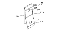
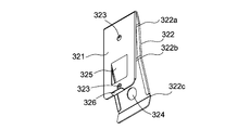
- 6A, 6B, and 6C are schematic views showing the configuration of the main body side guide portion provided in the baking chamber of the automatic bread maker of the present embodiment, FIG. 6A is a side view, and FIG. FIG. 6C is a perspective view when viewed obliquely from below.
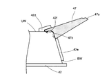
- the main body side guide portion 32 is a plate-like fixing portion 321 that is a portion attached to the inner surface side of the side wall 30 b constituting the baking chamber 30, and is folded back with respect to the fixing portion 321 and protrudes toward the inside of the baking chamber 30. And a projecting piece 322 (corresponding to the engaging projection of the present invention).
- the main body side guide portion 32 is obtained integrally, for example, by bending a sheet metal, and also exhibits a function as a leaf spring member.
- the fixing portion 321 is provided with screw fixing holes (screw holes 323) at two locations, and in the present embodiment, the main body side guide portion 32 is fixed to the side wall 30b using screws. It has become.
- the fixing method of the main body side guide portion 32 to the side wall 30b may of course be a method other than screwing, and if a method other than screwing is adopted, the screw hole 323 is not necessary.
- the main body side guide portion 32 is fixed so that the upper end portion thereof is positioned in the vicinity of the upper end portion of the baking chamber 30.
- the folding piece 326 provided at the lower end of the fixing portion 321 is used for positioning when the main body side guide portion 32 is attached to the side wall 30b, but may be erased depending on circumstances.
- a through hole 324 is formed above and below the projecting piece 322. This is so that when the main body side guide portion 32 is fixed to the side wall 30b using a screw, a screw is inserted from the inside of the firing chamber 30 and can be screwed.
- the through hole 324 may not be provided as appropriate.
- a first bent portion 322a, a second bent portion 322b, and a third bent portion 322c are formed in order from the top to the bottom.
- the first bent part 322a reduces the inclination angle (projection amount) of the protruding piece part 322 with respect to the fixed part 321.
- the second bent portion 322b increases the inclination angle (projection amount) of the protruding piece portion 322 with respect to the fixed portion 321.
- the protrusion piece 322 has a shape in which the upper side from the middle substantially protrudes less than the fixed part 321 and the lower side from the middle largely protrudes from the fixed part 321 in a side view.
- the third bent portion 322c is a portion that is bent in a direction to reduce the protruding amount of the protruding piece portion 322 with respect to the fixed portion 321 and is provided in consideration of safety and the like.
- an auxiliary protrusion 325 that protrudes toward the protrusion 322 side is formed on the lower side from the substantially middle of the fixed part 321.
- the auxiliary protruding piece 325 reinforces the elastic force of the protruding piece portion 322, but it does not necessarily have to be provided.
- a bread container support portion 14 (for example, die casting of an aluminum alloy) that supports the bread container 80 (or bread container 140) is provided at a location corresponding to the approximate center of the bottom wall 30 a of the baking chamber 30. Is made of).
- the bread container support 14 is formed so as to be recessed from the bottom wall 30a of the baking chamber 30, and the shape of the recess is substantially circular when viewed from above.
- Four engagement grooves 14a are formed on the inner wall of the bread container support portion 14 so as to be arranged at substantially equal intervals in the circumferential direction.
- the driving shaft 11 is supported at the center of the bread container support portion 14 so as to be substantially perpendicular to the bottom wall 30a.
- a main body side connecting portion 11 a is fixed to the upper end of the driving shaft 11.
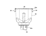
- FIGS. 4, 7A, 7B, and 7C are schematic views showing the configuration of the bread container provided in the automatic bread maker of the present embodiment
- FIG. 7A is a side view
- FIG. 7B is a perspective view seen obliquely from above
- FIG. It is the perspective view seen from diagonally below.
- the bread container 80 is, for example, a die-cast molded product of aluminum alloy (others may be made of sheet metal or the like), and has a bucket-like shape.
- a flange 80a is formed on the opening side edge of the bread container 80 (in other words, “the upper end of the bread container 80 surrounds the opening”).
- a handle 85 for a handbag that is supported so as to be pivotable and can be laid up and down is attached to the collar portion 80a.
- the horizontal cross section of the bread container 80 is a rectangle with rounded corners.
- a concave portion 81 having a substantially circular shape in a plan view is formed on the bottom of the bread container 80 so as to accommodate a part of a blade unit 90 which will be described in detail later.
- a blade rotation shaft 82 (an example of the rotation shaft of the present invention) extending in the vertical direction is rotatably supported in a state where a countermeasure against sealing is taken.
- a container-side connecting portion 82a is fixed to the lower end of the blade rotation shaft 82 (projecting outward from the bottom of the bread container 80).
- a cylindrical base 83 is provided on the bottom outer surface side of the bread container 80 so as to surround the blade rotation shaft 82.
- the bread container 80 is accommodated (arranged at the set position) in the baking chamber 30 in a state where the pedestal 83 is received by the bread container support portion 14.
- the pedestal 83 may be formed separately from the bread container 80 or may be formed integrally with the bread container 80.
- the bread container 80 is lowered in position by adjusting the position so that the engagement protrusion 83a of the base 83 fits into the engagement groove 14a of the bread container support portion 14, and thereby the horizontal direction (a plane direction substantially perpendicular to the blade rotation shaft 82). ) Is attached to the baking chamber 30 in a state where the positioning is performed.
- the circumferential width of the engaging protrusion 83a is formed to be approximately the same size as the circumferential width of the corresponding engaging groove 14a (slightly smaller than the engaging groove 14a).
- the engaging grooves 14a and the engaging protrusions 83a may be provided so as to be positioned, and the number and size thereof can be changed as appropriate.
- an engagement protrusion may be provided on the inner wall of the bread container support portion 14, and an engagement groove may be provided on the base 83 of the bread container 80.
- the container side connection portion 82 a provided at the lower end of the blade rotation shaft 82, and the driving force
- the main body side connecting portion 11a fixed to the upper end of the shaft 11 is coupled.
- the blade rotation shaft 82 can transmit the rotational power from the driving shaft 11. That is, the main body side connecting portion 11a and the container side connecting portion 82a constitute a coupling CP (an example of the coupling of the present invention).
- a bread container side guide portion 84 is provided on each outer surface of two opposing side walls (side walls facing in the longitudinal direction) of the bread container 80.
- the bread container side guide portion 84 cooperates with the main body side guide portion 32 (see, for example, FIG. 4) so that the bread container 80 is smoothly accommodated in the baking chamber 30 and fixes the bread container 80. It also plays a role.
- the bread container side guide part 84 is formed integrally, for example, by bending a sheet metal.
- the bread container side guide portion 84 is fixed to the bread container 80 by using a stopper such as a screw or a rivet.
- a stopper such as a screw or a rivet.
- other methods may be used for fixing the bread container guide portion 84 to the bread container 80.
- the bread container side guide portion 84 extends in a direction (vertical direction) in which the bread container 80 is received in the baking chamber 30, and engages with the projecting portion 322 of the main body side guide portion 32 (the engagement groove of the present invention). Is an example).
- the vertical position of the engagement groove 841 is not particularly limited, but is provided closer to the upper part in this embodiment.
- the vertical width of the engagement groove 841 has a certain length so that the engagement range with the main body side guide portion 32 is widened.
- the engagement groove 841 is the bread container 80. It is the structure extended to upper end vicinity.
- the bottom surface of the engaging groove 841 has a step structure (the groove depth is deep on the upper side and the groove depth is shallow on the lower side). A configuration that does not occur (for example, a configuration in which the entire depth is the same as that of the lower portion of the present embodiment) may be used.
- FIGS. 8A, 8B and 8C are schematic diagrams for explaining the relationship between the main body side guide part and the bread container side guide part when the bread container is accommodated in the baking chamber.
- FIG. 8A shows a state before the main body side guide portion 32 and the bread container side guide portion 84 start to engage.
- FIG. 8B shows a state where the main body side guide portion 32 and the bread container side guide portion 84 are engaged, and the state before the bread container 80 reaches the set position of the baking chamber 30.
- FIG. 8C shows a state in which the main body side guide portion 32 and the bread container side guide portion 84 are engaged, and the bread container 80 has reached the set position of the baking chamber 30.
- the broken line arrows in FIGS. 8A and 8B indicate the moving direction of the bread container 80 when the bread container 80 is accommodated in the baking chamber 30 (the direction in which the bread container 80 is lowered).
- the engagement between the bread container side guide portion 84 and the main body side guide portion 32 is started.
- the Specifically, the projecting piece 322 of the main body side guide part 32 is sandwiched between the engagement grooves 841 of the bread container side guide part 84.
- the bread container 80 then moves while being guided by the main body side guide portion 32.
- the engagement between the engagement groove 14 a provided in the bread container support portion 14 and the engagement protrusion 83 a provided in the base 83 of the bread container 80 is reliably obtained.
- the main body side guide part 32 is provided so that the upper end side is located in the baking chamber 30 upper end part vicinity. For this reason, when the bread container 80 is accommodated in the baking chamber 30, before the base 83 of the bread container 80 reaches the bread container support part 14, the main body side guide part 32 guides the bread container side guide part 84. Is started. Further, when the bread container side guide portion 84 is in the vicinity of the upper end portion of the baking chamber 30, the main body side guide portion 32 is engaged with the bread container side guide portion 84, so that the user changes the orientation of the bread container 80. It can be easily adjusted while visually confirming the direction in which the engagement between the container side guide portion 84 and the main body side guide portion 32 is obtained.
- the protruding piece part 322 of the main body side guide part 32 starts to press the bread container 80.
- the protruding piece portion 322 has a configuration in which the upper side from the middle of the protruding piece portion 322 does not protrude so much with respect to the fixed portion 321. For this reason, at the engagement start stage, the force with which the projecting piece 322 presses the bread container 80 is small, and it is easy to move the bread container 80 downward.
- the fixed portion 321 of the projecting piece portion 322 of the main body side guide portion 32 is assumed.
- the greatly projecting portion (lower side) is engaged with the engaging groove 841 of the bread container side guide portion 84.
- the lower side of the projecting piece 322 is pushed by the bread container side guide 84 and greatly deformed.
- the bread container 80 is strongly pressed by the projecting piece 322, and the bread container 80 is fixed so as not to move (raise) in the baking chamber 30.
- the auxiliary protrusion 325 provided on the fixing portion 321 is pushed and deformed by the protrusion 322 in a state where the bread container 80 has reached the set position of the baking chamber 30, this auxiliary The reaction force of the projecting piece 325 also becomes a force for pressing the bread container 80. For this reason, the bread container 80 can be fixed more reliably.
- the bread container 140 has substantially the same structure as the bread container 80 (see FIGS. 24 and 25). That is, the bread container 140 is, for example, an aluminum alloy die-cast molded product (others may be made of sheet metal or the like), has a bucket-like shape, and has a flange 140a provided on the side edge of the opening. A hand handle 140b (see FIG. 25) is attached.
- the horizontal cross section of the bread container 140 is a rectangle with rounded corners. However, a recess corresponding to the recess 81 of the bread container 80 is not provided at the bottom of the bread container 140.
- a blade rotating shaft 142 extending in the vertical direction is rotatably supported in a state where measures against sealing are taken.
- a container-side connecting portion 142a is fixed to the lower end of the blade rotation shaft 142 (projecting outward from the bottom of the bread container 140).
- a cylindrical base 143 is provided on the outer surface side of the bottom of the bread container 140 so as to surround the blade rotation shaft 142.
- the bread container 140 is accommodated in the baking chamber 30 in a state where the base 143 is received by the bread container support part 14.
- the pedestal 143 may be formed separately from the bread container 140 or may be formed integrally with the bread container 140.
- the container side connection part 142 a provided at the lower end of the blade rotating shaft 142, and the driving force
- the main body side connecting portion 11a fixed to the upper end of the shaft 11 is coupled.
- the blade rotating shaft 142 can transmit the rotational power from the driving shaft 11. That is, the main body side connecting portion 11a and the container side connecting portion 142a constitute a coupling.
- the container side connection part 142a and the pedestal 143 have the same size and shape as the container side connection part 82a and the pedestal 83 of the bread container 80, but the portion corresponding to the container body above it is the bread container 80. It is made a little smaller than. For this reason, as will be described later, the bread container 140 can be stored in the bread container 80.
- a blade unit 90 is detachably attached to a portion of the blade rotation shaft 82 protruding into the bread container 80.
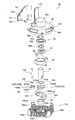
- the configuration of the blade unit 90 will be described with reference to FIGS. 9, 10, 11A, 11B, 12A, 12B, 13A, and 13B.
- the blade unit 90 includes a unit shaft 91, a crushing blade 92 that is attached to the unit shaft 91 so as not to rotate relative to the unit shaft 91, and a blade that is attached to the unit shaft 91 so as to be relatively rotatable and cover the crushing blade 92 from above.
- 12A and 12B show a state in which the guard 106 is removed.
- the crushing blade 92 is located at a position slightly above the bottom surface of the recess 81 of the bread container 80. Almost the entire grinding blade 92 and dome-shaped cover 93 are accommodated in the recess 81 (see FIG. 4).
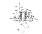
- the unit shaft 91 is a substantially cylindrical member formed of a metal such as a stainless steel plate, for example, and has an opening at one end (lower end), and the inside is hollow. That is, the unit shaft 91 has a configuration in which an insertion hole 91c is formed so that the blade rotation shaft 82 can be inserted from the lower end (see, for example, FIG. 11B).
- a pair of notches 91a are formed symmetrically arranged with the rotation center of the unit shaft 91 in between (see FIG. 10). Only one of the pair of notches 91a is shown).
- the side shape of the shape of the notch 91a is a vertically long rectangle, and the upper end is rounded.
- the notch 91a is provided to engage with a pin 821 (see FIG. 11B) penetrating the blade rotation shaft 82 horizontally. When the pin 821 of the blade rotating shaft 82 and the notch 91a are engaged, the unit shaft 91 is attached to the blade rotating shaft 82 so as not to be relatively rotatable.
- the center of the upper surface on the inner side of the unit shaft 91 so as to engage with the convex portion 82b provided at the central portion of the upper end surface (substantially circular) of the blade rotation shaft 82 (shown by a broken line).
- a concave portion 91b is formed in the portion. Accordingly, the blade unit 90 can be easily attached to the blade rotation shaft 82 in a state where the centers of the unit shaft 91 and the blade rotation shaft 82 are aligned. In addition, when the blade rotation shaft 82 is rotated, unnecessary rattling is suppressed.
- the convex portion 82b is provided on the blade rotating shaft 82 side and the concave portion 91b is provided on the unit shaft 91 side, but conversely, the concave portion is provided on the blade rotating shaft 82 side and the unit shaft 91 side is provided.
- a configuration in which a convex portion is provided may be employed.
- the pulverization blade 92 for pulverizing grains is formed by processing a stainless steel plate, for example. As shown in FIG. 10, the pulverizing blade 92 includes a first cutting portion 921, a second cutting portion 922, a connecting portion 923 that connects the first cutting portion 921 and the second cutting portion 922, and Is provided. An opening 923 a having a planar shape is formed at the center of the connecting portion 923. The crushing blade 92 is attached to the unit shaft 91 such that the lower side of the unit shaft 91 is fitted into the opening 923a.
- a flat surface is formed by shaving a part of the side surface (near the position where the notch 91a is provided).
- the lower side of the unit shaft 91 has a cross section that has substantially the same shape (oval shape) as the opening 923 a provided in the connecting portion 923. Since such a shape is adopted, the pulverization blade 92 attached to the unit shaft 91 cannot be rotated relative to the unit shaft 91.
- the cross-sectional area of the lower part of the unit shaft 91 is slightly smaller than the opening 923a, so that the unit shaft 91 and the grinding blade 92 can be fitted. Since the stopper member 94 for preventing the retaining member 94 is fitted into the unit shaft 91 on the lower side of the pulverizing blade 92, the pulverizing blade 92 does not fall off the unit shaft 91.
- the dome-shaped cover 93 disposed so as to surround and cover the crushing blade 92 is made of, for example, an aluminum alloy die-cast product, and a bearing 95 (in this embodiment, a rolling bearing is used on the inner surface side thereof. ) (See FIG. 11B) is formed.
- the dome-shaped cover 93 has a configuration in which a substantially cylindrical convex portion 93a is formed in the central portion when viewed from the outer surface. No opening is formed in the convex portion 93 a, and the bearing 95 accommodated in the accommodating portion 931 is in a state where the side surface and the upper surface are enclosed by the wall surface of the accommodating portion 931.
- An inner ring 95a is attached to the unit shaft 91 in a state in which the bearing 95 is provided with upper and lower retaining rings 96a and 96b so as not to rotate relative to the unit shaft 91 (the unit shaft 91 is press-fitted into a through hole inside the inner ring 95a. Have been).
- the bearing 95 is press-fitted into the housing portion 931 so that the outer wall of the outer ring 95b is fixed to the side wall of the housing portion 931.
- the dome-shaped cover 93 is attached to the unit shaft 91 so as to be rotatable relative to the bearing 95 (the inner ring 95a rotates relative to the outer ring 95b).
- the housing portion 931 of the dome-shaped cover 93 is, for example, silicon-based or fluorine-free so that foreign matter (for example, liquid used when pulverizing grain grains or paste-like material obtained by pulverization) does not enter the bearing 95 from the outside.
- a seal material 97 formed of a system material and a metal seal cover 98 that holds the seal material 97 are press-fitted from the lower side of the bearing 95.
- the seal cover 98 is fixed to the dome-shaped cover 93 with a rivet 99 so that the fixing to the dome-shaped cover 93 is ensured. Fixing with rivets 99 is not essential, but it is preferable to do so in order to obtain secure fixing.
- a kneading blade 101 (for example, aluminum) in a planar shape is formed by a support shaft 100 (see FIG. 10) arranged so as to extend in a vertical direction at a location adjacent to the convex portion 93 a. (Made of die-cast alloy product) is attached.
- the kneading blade 101 is attached to the support shaft 100 so as not to be relatively rotatable, and moves together with the support shaft 100 attached to the dome-shaped cover 93 so as to be relatively rotatable. In other words, the kneading blade 101 is attached to the dome-shaped cover 93 so as to be relatively rotatable.
- a cushioning material 107 is attached to one surface near the tip of the kneading blade 101 (assuming a portion that draws the largest circle when the kneading blade 101 is rotated about the support shaft 100).
- the buffer material 107 is provided so as to slightly protrude from the tip of the kneading blade 101 (see, for example, FIG. 12B). In the present embodiment, it is provided so as to protrude about 3 mm (d ⁇ 3 mm).
- the buffer material 107 is fixed by holding the buffer material 107 between the side surface of the kneading blade 101 and the fixing plate 108, inserting a rivet 109 from the other side of the kneading blade 101, and caulking.
- the number of rivets 109 is two, but it goes without saying that the number is not limited.
- the cushioning material 107 is for preventing the kneading blade 101 in an open posture (details will be described later) from directly contacting the bread container 80 (the inner wall thereof).
- the kneading blade 101 and the bread container 80 are in direct contact with each other, damage may occur due to interference between them, and the buffer material 107 is provided to prevent such damage.
- the surface of the bread container 80 and the kneading blade 101 is coated with fluorine.
- the buffer material 107 of the present embodiment is provided so that the fluorine coating is not peeled off by contact between the kneading blade 101 and the pan container 80.
- the material constituting the cushioning material 107 is preferably a material softer than the coating material so as not to peel off the fluorine coating.
- silicone rubber or TPE Thermoplastic Elastomers
- the buffer material 107 also functions as a soundproofing measure, which will be described later. Note that the cushioning material 107 may also be described as a part of the kneading blade 101.
- a complementary kneading blade 102 (for example, made of an aluminum alloy die-cast product) is fixedly arranged on the outer surface of the dome-shaped cover 93 so as to be aligned with the kneading blade 101.
- the complementary kneading blade 102 is not essential, but is preferably provided in order to increase the kneading efficiency in the kneading process for kneading the bread dough.
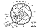
- the kneading blade 101 rotates around the axis of the support shaft 100 together with the support shaft 100, and has a folded posture shown in FIGS. 9, 11A, 11B, 12A and 13A and an open posture shown in FIGS. 12B and 13B. Take 2 postures.
- the kneading blade 101 in the folded position is stopped from rotating by a stopper portion 93b provided on the inner surface of the dome-shaped cover 93, and further rotated counterclockwise (assuming when viewed from above) with respect to the dome-shaped cover 93. Can not do.
- the tip of the kneading blade 101 protrudes slightly from the dome-shaped cover 93.
- the tip of the kneading blade 101 Protrudes greatly from the dome-shaped cover 93.
- the opening angle of the kneading blade 101 in the opening posture is also limited by the stopper portion 93b.
- the kneading blade 101 reaches the maximum opening angle when a second engagement body 103b (fixed to the support shaft 100), which will be described later, hits the stopper portion 93b and cannot rotate.
- the complementary kneading blade 102 is aligned with the kneading blade 101, and the size of the k-shaped kneading blade 101 is increased. It becomes like this.
- the first engagement body 103a (see FIG. 10) constituting the cover clutch 103 is attached to the unit shaft 91 between the grinding blade 92 and the seal cover 98.
- the first engaging body 103a made of a zinc die-cast product has a planar oval shape opening 103aa, and the lower oval cross section of the unit shaft 91 is fitted into the opening 103aa, so that the first The engaging body 103 a is not rotatable relative to the unit shaft 91.
- the first engaging body 103a is attached from the lower side of the unit shaft 91 prior to the pulverizing blade 92, and the stopper member 94 prevents the detachment from the unit shaft 91 together with the pulverizing blade 92.
- the washer 104 is arranged between the first engagement body 103a and the seal cover 98 in consideration of prevention of deterioration of the first engagement body 103a, but the washer 104 is not essential.
- 2nd engaging body 103b which comprises the clutch 103 for a cover in cooperation with the 1st engaging body 103a is attached to the lower side of the spindle 100 to which the kneading blade 101 is attached.
- the second engagement body 103b made of a zinc die-cast product has a planar oval shape opening 103ba, and the oval cross section on the lower side of the support shaft 100 is fitted into the opening 103ba, thereby The two engagement bodies 103b are not rotatable relative to the support shaft 100.
- the washer 105 is arranged above the second engagement body 103b in consideration of prevention of deterioration of the second engagement body 103b, but the washer 105 is not essential.
- the cover clutch 103 composed of the first engagement body 103a and the second engagement body 103b functions as a clutch for switching whether or not to transmit the rotational power of the blade rotation shaft 82 to the dome-shaped cover 93.
- the cover clutch 103 is a rotation direction of the blade rotation shaft 82 when the kneading motor 50 rotates the driving shaft 11 (this rotation direction is referred to as “forward rotation”.
- FIGS. 12A and 12B rotate counterclockwise. 13A and 13B, the rotational power of the blade rotation shaft 82 is transmitted to the dome-shaped cover 93.
- the rotation direction of the blade rotation shaft 82 when the crushing motor 60 rotates the drive shaft 11 this rotation direction is referred to as “reverse rotation”.
- cover clutch 103 does not transmit the rotational power of the blade rotating shaft 82 to the dome-shaped cover 93.
- the structure and operation of the cover clutch 103 will be described in more detail.
- the second engaging body 103b has engaging portions at two locations on the side surface. One is a first engagement portion 103bb which is an engagement portion with respect to the first engagement body 103a, and the second is a second engagement portion 103bc which is an engagement portion with respect to the stopper portion 93b.
- the first engagement portion 103bb of the second engagement body 103b is the engagement portion 103ab (2 in this embodiment) of the first engagement body 103a.
- the second engaging portion 103bc engages with the stopper portion 93b (see FIG. 12A).
- the stopper portion 93b functions as an angle determining unit that determines an angle when the kneading blade 101 is in the folded posture.
- the force transmitted from the first engagement body 103a to the second engagement body 103b holds not only the support shaft 100 to which the kneading blade 101 is attached but also the support shaft 100 through the engagement of the second engagement body 103b and the stopper portion 93b. Since the dome-shaped cover 93 is also received, the rotational power of the blade rotating shaft 82 is reliably transmitted to the kneading blade 101 when the kneading blade 101 enters the kneading posture by being folded.
- the first engagement portion 103bb of the second engagement body 103b is retracted from the rotation track of the engagement portion 103ab of the first engagement body 103a. Angle (see FIG. 12B). For this reason, even if the blade rotation shaft 82 rotates, the first engagement body 103a and the second engagement body 103b are not engaged. Accordingly, the rotational power of the blade rotation shaft 82 is not transmitted to the dome-shaped cover 93. At this time, the second engagement portion 103bc of the second engagement body 103b is detached from the stopper portion 93b.
- the dome-shaped cover 93 is formed with a window 93d that communicates the space inside the cover and the space outside the cover.
- the window 93d is arranged at a height equal to or higher than the grinding blade 92.
- a total of four windows 93d are arranged at intervals of 90 °, but other numbers and arrangement intervals can be selected.
- a total of four ribs 93e are formed on the inner surface of the dome-shaped cover 93 corresponding to each window 93d (see FIGS. 12A and 12B).
- Each rib 93e extends obliquely from the vicinity of the center of the dome-shaped cover 93 to the outer peripheral annular wall with respect to the radial direction, and the four ribs 93e form a kind of bowl shape.
- each rib 93e is curving so that the side which faces the bread raw material pressed toward it may become convex.
- a guard 106 is detachably attached to the lower surface of the dome-shaped cover 93.
- the guard 106 covers the lower surface of the dome-shaped cover 93 and prevents the user's finger from approaching the crushing blade 92.
- the guard 106 is made of heat-resistant engineering plastic, and can be a molded product such as PPS (polyphenylene sulfide).
- the guard 106 may not be provided, but is preferably provided for the purpose of ensuring the safety of the user.
- the guard 106 there is a ring-shaped hub 106a through which a stopper member 94 fixed to the unit shaft 91 is passed.
- a ring-shaped rim 106b provided concentrically outside the hub 106a.
- the hub 106a and the rim 106b are connected by a plurality of spokes 106c.
- the plurality of spokes 106c are arranged at a predetermined interval, and between the spokes 106c are openings 106d through which grain grains pulverized by the pulverizing blade 92 pass.
- the opening 106d has a size that prevents a finger from passing through.
- the guard 106 is shaped like an outer blade of a rotary electric razor, and the grinding blade 92 is shaped like an inner blade.
- a total of four columns 106e are integrally formed at the periphery of the rim 106b at intervals of 90 °.
- a horizontal groove 106ea with one end dead end is formed on the side surface of the column 106e facing the guard 106 center side.
- the guard 106 is attached to the dome-shaped cover 93 by engaging the grooves 106 ea with the projections 93 f formed on the outer periphery of the dome-shaped cover 93 (also four at a 45 ° interval).
- the groove 106ea and the protrusion 93f are provided so as to constitute a bayonet coupling.
- the side surface 106eb serving as the front surface in the rotation direction is inclined obliquely upward.
- the crushing blade 92 and the kneading blade 101 are incorporated into one unit (blade unit 90), the handling thereof is convenient.
- the user can easily pull out the blade unit 90 from the blade rotating shaft 82, and can easily clean the blade after the bread making operation.
- the pulverizing blade 92 provided in the blade unit 90 is detachably attached to the unit shaft 91, and is easily mass-produced and has excellent maintainability such as blade replacement.
- the bearing 95 Since a liquid such as water is put in the pan container 80, it is preferable that the bearing 95 has a sealed structure so that the liquid does not enter the bearing 95.
- the sealing means (the sealing material 97 and the seal cover only on the inner surface side of the dome-shaped cover 93). 98), a structure for sealing the bearing 95 is obtained. For this reason, it is not necessary to provide sealing means above and below the bearing 95, and the seal structure of the bearing 95 can be downsized. For this reason, in the automatic bread maker 1, it is possible to suppress an adverse effect on the shape of the baked bread (for example, the bottom surface of the bread is greatly recessed).
- a kneading blade (not shown) is attached to a portion of the blade rotating shaft 142 that protrudes into the bread container 140 so that it cannot be relatively rotated and can be inserted and removed.
- This kneading blade has a simple shape used in a conventional automatic bread maker.
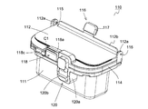
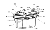
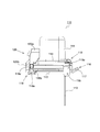
- FIG. 14A, FIG. 14B, FIG. 15, FIG. 16, FIG. 17, FIG. 17 show the structure of the bread ingredient storage container 110 provided in the automatic bread maker 1 and the structure for attaching the bread ingredient storage container 110 to the lid 40.
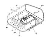
- FIGS. 18A, 18B and 19 show the front side of the main body 10 in the state in which the lid 40 to which the bread ingredient storage container 110 is attached.
- the front side of the main body 10 is the front side of the bread ingredient storage container 110
- the front side of the main body 10 is the rear side. It demonstrates as a back surface of the bread raw material storage container 110.
- FIG. 18A, 18B and 19 show a state in which the bread ingredient storage container 110 is attached to the lid 40.
- FIG. 14A, FIG. 14B, and FIG. A container lid 112 for opening and closing the opening 111a of the main body 111.
- the container main body 111 is a box-shaped member whose cross-sectional shape is substantially rectangular as shown in FIG.
- the container main body 111 is made of a metal such as aluminum or iron, which is difficult to be charged with static electricity so that powder bread materials (for example, gluten and dry yeast) can be prevented from adhering to the inside of the container main body 111.
- the inner surface of the container body 111 is covered with a coating layer CL made of, for example, a silicon-based or fluorine-based material.
- the inner surface of the container body 111 is not formed with irregularities due to rivets, screws, or the like, and the inner surface of the container body 111 is a smooth surface.
- the container main body 111 is formed with a flange portion (flange portion) 111b protruding outward from the side edge of the opening portion 111a.
- the flange 111b is formed on the entire circumference of the container body 111.
- a silicon-based packing (an embodiment of a seal member) 113 is fixed to the flange 111b.
- the external appearance of the packing 113 is a substantially frame shape, and the packing 113 is fixed to the entire periphery of the flange 111b. More specifically, the packing 113 protrudes from the substantially U-shaped section 113a attached so as to sandwich the flange 111b from above and below, and protrudes from the approximately U-shaped section (projecting upward in FIG. 15). And a thin-walled elastic portion 113b that is folded back so that the tip side faces in the direction opposite to the direction toward the opening 111a.
- the packing 113 protrudes from the opening 111a of the container main body 111, the bread raw material stored in the container main body 111 is easily caught by the packing 113, which causes the bread raw material to remain in the container.
- the packing 113 is attached to the container main body 111 so as not to protrude into the opening 111a. Further, when the packing 113 is fixed to the container lid 112 side, when the bread ingredients are put into the bread container 80 from the bread ingredient storage container 110, the bread ingredients are easily caught by the packing 113, and the amount of the bread ingredients to be charged is reduced. It becomes inappropriate. Considering this point, the packing 110 is fixed to the container body 111 side.
- the packing 113 is fixed to the container main body 111 (the flange 111b) by a container cover 114 attached to the container main body 111 so as to sandwich the substantially U-shaped portion 113a. That is, the container cover 114 functions as a fixing member that fixes the packing 113 to the container body 111.
- the container cover 114 is composed of two parts in detail, and these two parts are arranged so as to sandwich the flange 111b together with the packing 113, and then screwed, so that the packing 113 by the container cover 114 is fixed. Fixing is realized.
- the container cover member 114 is not particularly limited, and is formed of, for example, polybutylene terephthalate (PBT) resin in which a glass filler is dispersed.
- PBT polybutylene terephthalate
- the container lid 112 is made of a substantially rectangular metal plate having a slightly larger area than the opening 111a of the container body 111.
- the container lid 112 is formed of a metal such as aluminum for the same reason as the container main body 111 (suppression of adhesion of the powder bread raw material). Further, for the same reason as in the case of the container main body 111, the inner surface thereof (which is an expression assuming that the container lid 112 is closed) is covered with a coating layer CL made of a silicon-based material or the like.
- the container lid 112 is provided with attachment portions 112a having engagement holes at both end portions on the back side (one end side).
- the attachment portion 112a is formed by bending a part of the container lid 112.
- a support shaft 115 (provided at both end portions on the back side) fixed to the container main body 111 is fitted into the engagement hole of the attachment portion 112a.
- the container lid 112 is pivotally supported by the support shaft 115 fixed to the container body 111 on the back side (one end side), and the front side (the other end side facing the one end side) is opened. It is designed to rotate in a direction that is in contact with and away from the portion 111a.
- a part of the end of the container lid 112 is bent in a direction away from the opening 111a (bent approximately 90 ° in the present embodiment) to form a bent portion 112b.
- the bent portion 112b may not be formed, but is provided to prevent the end surface of the container lid 112 from being caught by the packing 113 or damaging the packing 113 when the container lid 112 is opened. Is preferred.
- a protrusion 116 having a substantially rectangular shape in plan view that protrudes obliquely upward (external direction) is provided at the substantially central portion of the bent portion 112b of the container lid 112. ing.
- the protrusion 116 is formed integrally with the container lid 112, but not limited to this, the container lid 112 and the protrusion 116 may be separate members.
- the protruding portion 116 protrudes from the container lid 112 so that the protruding position is located on the outer peripheral side (the position on the right side of the supporting shaft 115 in FIG. 16) from the support shaft 115 (which is the rotation center of the container cover 112). Is provided. For this reason, the container lid 112 can be easily rotated and opened by pressing the front surface 116a (see FIG. 14B) of the protrusion 116. That is, the protrusion 116 has a function of assisting an operation (by the user) to open the container lid 112. Of course, the size and shape of the protrusion 116 may be appropriately changed.
- the protrusion 116 is provided so as to exhibit the following stopper function.
- the bread ingredient storage container 110 is in a posture as shown in FIG. That is, the bread raw material storage container 110 is used with the container lid 112 positioned downward with respect to the container body 111. For this reason, when the container lid 112 changes from the closed state to the opened state (the state shown in FIG. 16), the container lid 112 rotates about the support shaft 115 by its own weight. When the container lid 112 is opened, if the opening angle becomes too large, there is a problem in that the amount of bread ingredients that spill outside the bread container 80 is not charged.
- the protrusion 116 is not opened (rotated) beyond a certain angle (in this embodiment, 95 ° with respect to the opening surface of the container main body 111), and the protrusion 116 is formed in the container main body 111 (details). Is configured to collide with a part of the container cover 114. That is, the protrusion 116 functions as a stopper that regulates the opening angle (amount) of the container lid 112.
- the restriction position of the opening amount of the container lid 112 by the protrusion 116 is adjusted so that the maximum value of the opening angle of the container lid 112 is 95 ° which is larger than 90 °. Has been.
- the container lid 112 can be kept open without being supported by hand, and the bread raw material can be easily put into the container body 111.
- the limit value of the opening angle is an example, and it is needless to say that various changes can be made.
- the configuration of the protrusions 116 is adjusted so that the amount of bread spilled out of the bread container 80 is reduced as much as possible, and the workability at the time of charging the bread ingredients into the bread raw material storage container 110 is ensured. That's fine.
- the structure which maintains the open state, without supporting the container lid 112, for example is also possible by making the bottom surface (assuming the case where it arrange
- the protrusion 116 is covered with an elastic cover member 117 formed using a material such as silicon.
- the cover member 117 may not be provided, but is preferably provided to protect the user's finger and the like. Further, as described above, the protruding portion 116 collides with the container main body 111 (more specifically, a part of the container cover 114) to restrict the opening amount of the container lid 112. By providing the elastic cover member 117 on the protrusion 116, the impact at the time of the collision can be reduced (the collision sound can be suppressed). Also from this point, it is preferable to provide the cover member 117.
- the cover member 117 may be a hollow member having one end opened so that the cover member 117 is simply covered with the projection 116, but in the present embodiment, the cover member 117 is provided on the projection 116 so that the cover member 117 is not easily detached. It has the structure which has the engagement protrusion 117a inserted by the engagement hole (refer FIG. 14B). Then, the engagement protrusion 117a fitted in the engagement hole provided in the protrusion 116 is for the container attached to the container body 111 when the container lid 112 is opened at a certain angle (95 ° in this embodiment). The cover 114 is in contact with a part of the cover 114.
- a movable locking member 118 is attached to the container cover 114 on the front side of the bread ingredient storage container 110.
- the lock member 118 has a mounting portion 118a having a mounting surface (see, for example, FIG. 16) that is substantially L-shaped in side view, and protrudes from the mounting portion 118a toward the opening 111a of the container main body 111.
- a hook portion 118b is provided so that the lid 112 can be pressed from the outer surface side, and an arm portion 118c extending in a direction substantially parallel to the longitudinal direction of the container body 111 from the placement portion 118a.
- the arm portion 118c is pivotally supported by the container cover 114 so as to be rotatable around a rotation axis C1 (see FIG. 14A) substantially parallel to the depth direction of the container body 111.
- the arm portion 118c is biased at one end by a biasing member (not shown), and the placing portion 118a and the hook portion 118b provided on the other end side of the arm portion 118c are subjected to the biasing force by the container body 111. Is directed toward the opening 111a.
- the hook portion 118b is provided in a substantially triangular shape in cross section, and a force is applied downward (expression based on the postures of FIGS. 14A, 14B, and 17) with the container lid 112 placed on the hook portion 118b.
- a force against the urging force of the urging member that urges the arm portion 118c is generated.
- the arm portion 118c is caused by a force against the urging force of the urging member when the container lid 112 is placed on the hook portion 118b.
- the hook portion 118b moves away from the container lid 112.
- the hook portion 118b moves to the container lid 112 side because the arm portion 118c is rotated by the biasing force of the biasing member. It reaches the position to be pressed from the outer surface side. Thereby, the locked state (state in which the closed state of the container lid 112 is maintained) is obtained.
- the outer peripheral side of the inner surface of the container lid 112 is in contact with the elastic portion 13 b of the packing 113 and overlaps with the flange portion 111 b, so that the opening 111 a is completely covered.
- the gap between the flange 111b and the container lid 112 is sealed by the packing 113, it is difficult for moisture, dust or the like to enter the container main body 111 from the outside.
- the arm portion 118c rotates (rotates about the rotation axis C1) against the biasing force.
- the hook portion 118b may be moved to a position where the container lid 112 is not pressed from the outer surface side. Thereby, the container lid 112 is rotated by gravity (expression based on the state of FIG. 16), and a state in which the opening 111a is opened (open state) is obtained.
- an automatic charging solenoid (not shown) is provided in the main body 10 on the lower side of the operation unit 20 (see FIG. 1).
- the plunger protrudes from the opening 10b (see FIG. 1B) provided in the main body wall surface 10a adjacent to the lid 40.
- the protruding plunger presses the movable member 46 (see FIG. 18A) provided on the side wall 40a of the lid 40.
- the arm part 118c of the lock member 118 is pressed by the movement of the pressed movable member 46, and the arm part 118c rotates against the urging force of the urging member (not shown).
- the holding of the container lid 112 by the hook portion 118b is released, the container lid 112 is rotated by gravity, and the opening 111a is opened.
- the user When the user opens the container lid 112 of the bread ingredient storage container 110, the user places a finger (for example, the left hand thumb) on the placement surface of the placement portion 118a and applies outward force (to the left in FIG. 17). Add As a result, the arm portion 118c of the lock member 118 is rotated, and the hook portion 118b moves to a position where the outer surface of the container lid 112 is not pressed. In this state, the container lid 112 is opened by pressing the projection 116 outward with a finger (for example, the right thumb) (rightward in FIG. 17). That is, by providing the mounting portion 118a and the projection portion 116, the user can easily open the container lid 112. As described above, since the placement surface on which the finger is placed has a substantially L-shape when viewed from the side, the placement portion 118a has good finger engagement.
- a finger for example, the left hand thumb
- the container cover 114 included in the bread ingredient storage container 110 has a first engagement portion 119 provided on the back side so that the bread ingredient storage container 110 can be held by the lid 40. And a second engagement portion 120 provided on the front surface side. That is, the first engagement portion 119 and the second engagement portion 120 constitute an attachment mechanism for attaching the bread ingredient storage container 110 to the lid 40.
- the first engagement portion 119 has a first engagement inclined surface 119a that protrudes outward from the side surface of the container cover 114 (projects obliquely upward in FIG. 19).
- a total of four first engaging portions 119 are provided in the vicinity of both end portions on the back side, two in close proximity to each other.
- the number and arrangement of the engaging portions 119 are examples, and may be changed as appropriate.
- the second engagement portion 120 includes a housing portion 120a and a mounting hook portion (movable hook portion) 120b in which a part of the housing portion 120a is accommodated.
- the mounting hook portion 120b is urged outward (in the left direction in FIG. 19) by a biasing member 120c (see FIG. 19) provided inside the housing portion 120a in a direction substantially parallel to the lateral direction of the container body 111. Yes. Further, when a force is applied in a direction against the urging force of the urging member 120c (toward the right in FIG. 19), the mounting hook portion 120b can move in that direction, and the amount of protrusion from the housing portion 120a can be reduced. It is variable.
- a frame member 42 (for example, made of an aluminum alloy die-cast product) is accommodated inside the lid 40 of the automatic bread maker 1, and the frame member 42 is formed on the inner cover 43 (for example, made of sheet metal) from the back side of the lid 40. ).
- This frame member is an example of a holding member having a storage space into which the bread ingredient storage container 110 can be detachably fitted.
- a portion of the frame member 42 that is close to the front surface of the main body 10 when the lid 40 is in a closed state has a substantially rectangular shape (assuming that the lid 40 is viewed from the back surface side) surrounded by the wall portion 42a.
- a hole 44 is provided.
- the wall portion 42 a abuts on the observation window 41 disposed on the upper surface side of the lid 40 and supports the observation window 41.
- the through hole 44 is formed so that the area when viewed in plan toward the viewing window 41 is gradually reduced.
- the viewing window 41 is considerably larger than the size of the through hole 44 in consideration of the design (not limited to this configuration, for example, the through hole 44 and the like).
- the viewing windows 41 may be substantially the same size).
- the internal structure of the lid 40 can be seen on the outside of the wall portion 42a.
- a space 45 formed by the dome-shaped wall 42b is formed in a portion near the back surface of the main body 10 when the lid 40 is closed.
- This space 45 is a storage space in which the bread ingredient storage container 110 can be detachably fitted.
- a front surface (left side in FIG. 19) in the storage space 45 is engaged with the mounting hook portion 120b of the second engagement portion 120 when the bread ingredient storage container 110 is stored in the storage space 45.
- a joint groove 45a is formed.
- the second engagement is brought into contact with the first engagement inclined surface 119a.
- a combined inclined surface 45b is formed.
- the user can force the mounting hook portion 120b of the second engagement portion 120 into the housing portion 120a (the biasing force of the biasing member 120c). Force in the direction opposite to the above). Then, in a state where the protruding amount of the mounting hook portion 120b from the housing portion 120a is reduced, the first engaging inclined surface 119a does not collide with the second engaging inclined surface 45b in the bread raw material storage container 110. Inclined and pushed into the holding part 45. Thereafter, the force applied to the mounting hook portion 120b is removed, the mounting hook portion 120b is projected, and the mounting hook portion 120b and the engaging groove 45a are engaged.
- the bread raw material storage container 110 when the bread raw material storage container 110 is fitted into the storage space 45, when the lid 40 is in a closed state (the state shown in FIG. 19 is applicable), the first engagement inclined surface 119a and the second engagement are provided.
- the joint inclined surface 45b comes into contact.
- the bread raw material storage container 110 is the direction in which the upward force in the vertical direction (upward in FIG. 19) from the second engagement inclined surface 45b and the engagement with the engagement groove 45a of the mounting hook portion 120b are released. And a force in the opposite direction (a leftward force in FIG. 19). Therefore, in the storage space 45, the bread ingredient storage container 110 has an engagement groove 45a that engages with the hook portion 120b for attachment and a second engagement inclined surface 45b that contacts the first engagement inclined surface 119a. And are held in the accommodating space 45.
- the hook part 120b for attachment is pressed in the direction retracted in the housing part 120a, and engagement with the hook part 120b for attachment and the engagement groove 45a is carried out. To release. Then, the first engagement inclined surface 119a may be pulled out obliquely so as not to be disturbed by the second engagement inclined surface 45b. That is, the user can easily attach and remove the bread ingredient storage container 110 to and from the lid 40 by simply pressing a part of the attaching hook portion 120b.
- the container main body 111 is used for fixing (fixing using a rivet or the like). Irregularities may be formed in 111.
- the bread raw material tends to remain in the container main body 111 in which the powder bread raw material is stored, which is not preferable (however, the present invention is not intended to exclude such a configuration).
- the container cover 114 is provided with the second engagement portion 120, the lock member 118, and the like, such a problem can be avoided.
- the lid 40 of the automatic bread maker 1 is provided with an exhaust path which is a characteristic configuration of the automatic bread maker according to the present invention.
- the exhaust path referred to here is an exhaust path for discharging steam, hot air, etc. generated in the firing chamber 30.
- the configuration of the exhaust path will be described.
- a duct 47 is disposed between the frame member 42 and the lid 40.
- the duct 47 includes a first opening 47a formed at one end, a second opening 47b formed at the other end, and a hollow space 47c that connects the first opening 47a and the second opening 47b (whichever And FIG. 19).
- the end of the duct 47 on the side where the first opening 47 a is provided is an exhaust port 40 b (substantially rectangular in plan view) provided near the upper back side of the lid 40 of the automatic bread maker 1. It is designed to be fitted.
- the duct 47 has a structure in which the thickness gradually increases from one end where the first opening 47a is provided to the other end where the second opening 47b is provided, and the duct 47 extends from the exhaust port 40b. It is configured not to protrude to the outside.
- FIG. 20 is a schematic plan view showing a configuration of a lid provided in the automatic bread maker of the present embodiment, in which the inner cover (indicated by reference numeral 43 in FIGS. 18A, 18B, and 19) and the bread raw material storage container are removed. It is a figure at the time of seeing a state from the lower surface side of a lid.
- 21A and 21B are schematic plan views for explaining the relationship between the frame member and the duct included in the automatic bread maker of the present embodiment, and FIG. 21A is a view when viewed along the arrow Y in FIG.
- FIG. 21B is a view when viewed along the arrow Z in FIG. 21A.
- FIG. 21A and FIG. 21B are views in a state where the front and back of the frame member 42 shown in FIG. 20 are turned over.
- each of the plurality of exhaust through-holes 42c formed is a frame member 42.
- the through hole formed in the upper wall UW near the rear surface (rightward in FIG. 19) and the through hole formed near the upper portion of the side wall BW on the back surface side of the frame member 42 are connected.
- the number and shape of the exhaust through holes 42c provided in the frame member 42 may be determined as appropriate, and are not limited to the configuration of the present embodiment.
- the plurality of exhaust through holes 42 c formed in the frame member 42 are in a state of being covered by the end portion of the duct 47 on the side where the second opening 47 b is provided. Yes.
- a broken line arrow indicates a range (maximum range) in which the exhaust through hole 42c is provided.
- the end of the duct 47 on the side where the second opening 47b is provided has a configuration in which the upper part protrudes from the lower part. Further, the end side surface of the duct 47 on the side where the second opening 47b is provided has a curved structure along the upper wall UW and the rear side wall BW of the frame member 42 as shown in FIG. 21B. With this configuration, the duct 47 can completely cover the plurality of exhaust through holes 42c provided in the frame member 42.
- An engaging protrusion 42d is formed on the outer surface side of the upper wall UW of the frame member 42 to fix the upper part on the end side where the second opening 47b of the duct 47 is provided.
- the engaging protrusion 42d has a shape in which the L-shape faces sideways as shown in FIG. 21B.
- the duct 47 has a frame member so that the upper part on the end side where the second opening 47b of the frame member 42 is provided is sandwiched in a space formed between the engagement protrusion 42e and the upper wall UW of the frame member 42. 42 is attached.
- the duct 47 is attached to the frame member 42 so that the lower part on the end side where the second opening 47b is provided is supported by the protruding piece 42e provided on the outer surface of the back side wall BW of the frame member 42. It has become. As described above, the duct 47 is fixed between the frame member 42 and the lid 40 without using a fixing member such as a screw or a rivet.
- the engagement protrusions 42d are provided at two locations.
- the number and shape of the engaging protrusions 42d are not limited to the configuration of the present embodiment and can be changed as appropriate.
- the engagement protrusions 42d provided on the outer surface side are indicated by broken lines.
- the protrusion piece 42e is provided in two places.
- the number and shape of the protruding pieces 42e are not limited to the configuration of the present embodiment and can be changed as appropriate.
- the engaging protrusions 42d and the protruding pieces 42e are preferably formed integrally with the frame member 42, but are not necessarily limited thereto.
- two positioning protrusions 42f are formed on the upper wall UW of the frame member 42 so that the position of the duct 47 attached to the frame member 42 is not displaced (see FIG. 21A). Thereby, the displacement of the duct 47 can be prevented and the attachment of the duct 47 to the frame member 42 is facilitated.
- the duct 47 is a separate member from the frame member 42, the shape of the frame member 42 does not have to be complicated, and an increase in mold cost can be suppressed.
- the exhaust port 40b formed in the lid 40 is formed closer to the upper back side (assuming the case where the lid 40 is in the closed position), the exhaust port 40b is disposed at a position away from the user. Will be. For this reason, it is preferable because it is possible to avoid a situation in which steam or the like from the exhaust port 40b is discharged toward the user.
- the exhaust port 40b is provided at a position where it is difficult for the user to see, the design is preferable.
- the duct 47 that connects the exhaust port 40b and the through hole 42c provided in the frame member 42 is provided. It is easy to make the configuration simple. As a result, it is easy to reduce the cost of the automatic bread maker 1. Moreover, since the structure of the duct 47 can be simplified as described above, the automatic bread maker 1 is also excellent in assemblability. Furthermore, since the duct 47 is attached without using a fixing member such as a screw or a rivet, the assembly of the exhaust path is easy.
- FIG. 22 shows a block configuration of the automatic bread maker 1.
- the automatic bread maker 1 is controlled by the control device 130.
- the control device 130 is configured by a microcomputer including a CPU (Central Processing Unit), a ROM (Read Only Memory), a RAM (Random Access Memory), an I / O (input / output) circuit unit, and the like.
- the control device 130 is preferably disposed at a position that is not easily affected by the heat of the baking chamber 30.
- the control device 130 has a time measurement function, and can perform temporal control in the bread manufacturing process.
- the control device 130 includes the operation unit 20 described above, the temperature sensor 15 that detects the temperature of the baking chamber 30, a kneading motor drive circuit 131, a pulverization motor drive circuit 132, a heater drive circuit 133, and a first solenoid.
- the drive circuit 134 and the second solenoid drive circuit 135 are electrically connected.
- the kneading motor drive circuit 131 controls the driving of the kneading motor 50 under a command from the control device 130.
- the crushing motor drive circuit 132 controls the driving of the crushing motor 60 under a command from the control device 130.
- the heater drive circuit 133 controls the operation of the sheathed heater 31 under a command from the control device 130.
- the first solenoid drive circuit 134 controls the driving of the automatic charging solenoid 16 that is driven when a part of the bread raw material is automatically charged in the course of the bread manufacturing process under a command from the control device 130.
- the second solenoid drive circuit 135 controls driving of the clutch solenoid 73 (see FIGS. 3A and 3B) that switches the state of the clutch 56 (see FIGS. 3A and 3B) under a command from the control device 130.
- the control device 130 reads a program relating to a bread manufacturing course (breadmaking course) stored in a ROM or the like based on an input signal from the operation unit 20, and a kneading blade by the kneading motor 50 via the kneading motor driving circuit 131.
- the automatic bread maker 1 controls the operation of the lock mechanism 118 by the automatic closing solenoid 16 via the solenoid driving circuit 134 and the switching control of the clutch 56 by the clutch solenoid 73 via the second solenoid driving circuit 135. Execute bread manufacturing process.
- a bread container 80 is set in the baking chamber 30. Then, according to the time chart of FIG. 23, the bread making course for rice grains is executed. In the bread making course for rice grains, the dipping process, the crushing process, the pause process, the kneading (kneading) process, the fermentation process, and the baking process are sequentially performed in this order.
- the user attaches the blade unit 90 to the blade rotation shaft 82 by covering the blade rotation shaft 82 of the bread container 80 with the unit shaft 91.
- the blade unit 90 includes the guard 106, the user's finger does not touch the crushing blade 92 during this work, and the user can work safely.
- the user weighs rice grains, water, and seasonings (for example, salt, sugar, shortening, etc.) in predetermined amounts and puts them in the bread container 80.
- the bread ingredients stored in the bread ingredient storage container 110 include gluten and dry yeast. Instead of gluten, at least one of wheat flour, thickener (eg, guar gum), and top fresh powder may be stored in the bread ingredient storage container 110. Further, for example, only dry yeast may be stored in the bread raw material storage container 110 without using gluten, wheat flour, thickener, super fresh powder or the like. Furthermore, depending on the case, seasonings such as salt, sugar and shortening may be stored together with gluten and dry yeast in the bread ingredient storage container 110 in order to be automatically added during the bread manufacturing process. Good.
- the bread raw material previously put into the bread container 80 is rice grains and water (in place of mere water, for example, a liquid having a taste component such as soup stock, a liquid containing fruit juice or alcohol, etc.) Become.
- the control apparatus 130 starts control operation
- the bread container 80 can be smoothly attached to the baking chamber 30 due to the presence of the main body side guide portion 32 and the bread container side guide portion 84.
- the main body side guide portion 32 extends to the vicinity of the upper end portion of the baking chamber 30.
- the main body side guide part 32 starts to engage with the bread container side guide part 84 when the bread container side guide part 84 is in the vicinity of the upper end part of the baking chamber 30.
- the pedestal 83 does not reach the bread container support part 14. Therefore, the user can easily adjust the orientation of the bread container 80 and attach the bread container 80 to the baking chamber 30.
- the main body side guide part 32 has elasticity, the bread container 80 can be firmly fixed. Further, in such a fixing method, the fixing function does not vary depending on the rotation direction of the blade rotation shaft 82.
- the dipping process is started by a command from the control device 130.
- the bread raw material previously put in the bread container 80 is set in a stationary state, and the stationary state is maintained for a predetermined time (30 minutes in the present embodiment).
- This dipping process is a process aimed at making the rice grains easy to be pulverized to the core in the subsequent pulverization process by adding water to the rice grains.
- the water absorption speed of rice grains varies depending on the temperature of the water. If the water temperature is high, the water absorption speed increases, and if the water temperature is low, the water absorption speed decreases. For this reason, you may make it fluctuate the time of an immersion process with the environmental temperature etc. in which the automatic bread maker 1 is used, for example. Thereby, it becomes possible to suppress the dispersion
- the grinding blade 92 may be rotated at the initial stage of the dipping process, and further, the grinding blade 92 may be intermittently rotated thereafter. If it does in this way, the surface of a rice grain can be damaged, and the liquid absorption efficiency of a rice grain will be improved.
- the crushing blade 92 is rotated at a high speed (for example, 7000 to 8000 rpm) in a mixture containing rice grains and water.
- the control device 130 controls the crushing motor 60 to rotate the blade rotation shaft 82 in the reverse direction (clockwise rotation in FIGS. 12A and 12B, and counterclockwise rotation in FIGS. 13A and 13B). Since the cutting blade of the crushing blade 92 is moved forward in the rotation direction by the reverse rotation of the blade rotation shaft 82, a crushing function using the crushing blade 92 is obtained.
- the control device 130 drives the clutch solenoid 73 so that the clutch 56 shuts off the power (the state shown in FIG. 3A). This is because, as described above, there is a possibility that the motor is damaged unless it is controlled in this way.
- the dome-shaped cover 93 also starts to rotate following the rotation of the blade rotation shaft 82.
- the rotation of the cover 93 is immediately blocked (stopped). It is preferable that the pulverizing blade 92 is rotated at a low speed in the initial stage of the pulverization process and then rotated at a high speed.
- the rotation direction of the dome-shaped cover 93 accompanying the rotation of the blade rotation shaft 82 for rotating the grinding blade 92 is the counterclockwise direction in FIGS. 13A and 13B, and the kneading blade 101 has been folded until then (see FIG. 13A).
- the resistance is changed to the open posture (posture shown in FIG. 13B) due to the resistance received from the mixture containing rice grains and water.
- the cover clutch 103 disconnects the blade rotation shaft 82 and the dome-shaped cover 93 from each other.
- a part of the kneading blade 101 in the open position (more precisely, the buffer material 107 provided on the tip side) is formed on the inner wall of the bread container 80 (specifically, the grinding efficiency is improved). In order to improve, it comes into contact with a bowl-shaped convex portion 80b) provided on the inner wall of the bread container 80. For this reason, the rotation of the dome-shaped cover 93 is prevented (stopped).
- the pulverization of the rice grains in the pulverization step is performed in a state in which water is soaked in the rice grains by the previously performed immersion step, so that the rice grains can be easily pulverized to the core.
- the rotation of the pulverizing blade 92 in the pulverization step is intermittent. This intermittent rotation is performed, for example, in a cycle of rotating for 30 seconds and stopping for 5 minutes, and this cycle is repeated 10 times. In the last cycle, the stop for 5 minutes is not performed.
- the rotation of the crushing blade 92 may be continuous rotation, but for the purpose of, for example, preventing the temperature of the raw material in the bread container 80 from becoming too high, it is preferable to perform intermittent rotation.
- the pulverization of the rice grains is performed in the dome-shaped cover 93 that has stopped rotating, and therefore the possibility that the rice grains scatter outside the bread container 80 is low. Further, the rice grains entering the dome-shaped cover 93 from the opening 106d of the guard 106 in the rotation stopped state are sheared between the stationary spoke 106c and the rotating pulverizing blade 92, so that the pulverization can be performed efficiently. Further, the rib 93e provided on the dome-shaped cover 93 suppresses the flow of the mixture containing rice grains and water (the flow in the same direction as the rotation of the pulverizing blade 92).
- the mixture containing the crushed rice grains and water is guided in the direction of the window 93d by the rib 93e of the dome-shaped cover 93, and is discharged out of the dome-shaped cover 93 from the window 93d. Since the rib 93e of the dome-shaped cover 93 is curved so that the side facing the mixture pressing toward it is convex, the mixture hardly stays on the surface of the rib 93e and flows smoothly toward the window 93d. . Instead of the mixture being discharged from the inside of the dome-shaped cover 93, the mixture existing in the space above the concave portion 81 enters the concave portion 81 and passes through the opening portion 106 d of the guard 106 from the concave portion 81. Get inside. Since the pulverization by the pulverization blade 92 is performed while being circulated as described above, the pulverization can be performed efficiently.
- the crushing process is completed in a predetermined time (in this embodiment, 50 minutes).
- the grain size of the pulverized powder may vary depending on the hardness of the rice grains and the environmental conditions.
- the end of the pulverization process may be determined using, for example, the magnitude of the load of the pulverization motor 60 (for example, it can be determined by the control current of the motor) as an index.
- the water vapor generated in this crushing process is difficult to enter the container of the bread ingredient storage container 110.
- the pause process is executed according to a command from the control device 130.
- the pause process is provided as a cooling period for lowering the temperature of the contents in the bread container 80 raised by the crushing process.
- the reason for lowering the temperature is that the next kneading step is carried out at a temperature at which the yeast is active (for example, around 30 ° C.).
- the pause process is fixed at a predetermined time (30 minutes), but the pause process may be continued until the temperature of the bread container 80 reaches a predetermined temperature.
- the kneading process is started by a command from the control device 130.
- the control device 130 drives the clutch solenoid 73 so that the clutch 56 transmits power (state shown in FIG. 3B).
- the control device 130 controls the kneading motor 50 to rotate the blade rotation shaft 82 in the forward direction (counterclockwise rotation in FIGS. 12A and 12B, clockwise rotation in FIGS. 13A and 13B).
- the grinding blade 92 When the blade rotation shaft 82 is rotated in the forward direction, the grinding blade 92 is also rotated in the forward direction. In this case, the pulverizing blade 92 rotates with the cutting blade behind in the rotation direction, and does not exhibit the pulverizing function. Due to the rotation of the grinding blade 92, the bread ingredients around the grinding blade 92 flow in the forward direction. Accordingly, when the dome-shaped cover 93 moves in the forward direction (clockwise in FIGS. 13A and 13B), the kneading blade 101 receives resistance from the non-flowing bread ingredients and is folded from the open position (see FIG. 13B). The angle is changed to (see FIG. 13A).
- the engaging portion 103bb of the second engaging body 103b has an angle that interferes with the rotation trajectory of the engaging portion 103ab of the first engaging body 103a.
- the cover clutch 103 connects the blade rotation shaft 82 and the dome-shaped cover 93, and the dome-shaped cover 93 enters a state of being driven in earnest by the blade rotation shaft 82.
- the dome-shaped cover 93 and the kneading blade 101 in the folded position rotate together with the blade rotation shaft 82 in the forward direction.
- the rotation of the blade rotation shaft 82 at the initial stage of the kneading process is preferably intermittent rotation or low speed rotation.
- the complementary kneading blades 102 are arranged on the extension of the kneading blade 101, so that the kneading blade 101 is enlarged and the bread raw material is pressed strongly. For this reason, the dough can be kneaded firmly.
- the rotation of the kneading blade 101 (this term is used as an expression including the complementary kneading blade 102 in the folded position, the same applies hereinafter) is very slow in the initial stage of the kneading process, and the speed is increased stepwise. Control is performed by the control device 130 as described above. In the initial stage of the kneading process in which the rotation of the kneading blade 101 is very slow, the control device 130 drives the automatic charging solenoid 16 to unlock the container lid of the bread ingredient storage container 110. Thereby, as shown in FIG. 1B, the container lid of the bread ingredient storage container 110 is opened, and the bread ingredients such as gluten and dry yeast are automatically charged into the bread container 80.
- the bread raw material storage container 110 is devised so that the bread raw material does not easily remain inside, the bread raw material storage container 110 can be completely charged without any bread raw material remaining.
- the automatic bread maker 1 is configured such that the viewing window 41 is on the front side and the bread ingredient storage container 110 is on the rear side when the lid 40 is closed.
- the container lid 112 is rotated toward the back side, and the plate-like surface is in a state substantially parallel to the vertical direction (state shown in FIG. 19). For this reason, even after the automatic feeding using the bread raw material storage container 110 is performed, it is not difficult to observe the state in the bread container 80 using the observation window 41.
- the bread raw material stored in the bread raw material storage container 110 is input while the kneading blade 101 is rotating.
- the present invention is not limited to this, and the bread ingredients stored in the bread ingredient storage container 110 may be input while the kneading blade 101 is stopped.
- the bread ingredients stored in the bread ingredient storage container 110 are put into the bread container 80, the bread ingredients are kneaded into one dough having a predetermined elasticity by the rotation of the kneading blade 101. Go.
- the kneading blade 101 swings the dough and knocks it against the inner wall of the bread container 80, an element of “kneading” is added to the kneading.
- the dome-shaped cover 93 also rotates.
- the rib 93e formed on the dome-shaped cover 93 also rotates, so that the bread material in the dome-shaped cover 93 is quickly discharged from the window 93d and the kneading blade 101 kneads the bread. Assimilate into a lump of material.
- the guard 106 is also rotated in the forward direction together with the dome-shaped cover 93.
- the spoke 106c of the guard 106 has a shape in which the center side of the guard 106 precedes and the outer peripheral side of the guard 106 follows when rotating in the forward direction.
- the guard 106 rotates in the forward direction to push the bread ingredients (bread dough) inside and outside the dome-shaped cover 93 outward with the spokes 106c. Thereby, the ratio of the raw material used as a waste after baking bread can be reduced.
- the pillar 106e of the guard 106 is configured such that when the guard 106 rotates in the forward direction, a side surface 106eb that is the front surface in the rotational direction is inclined upward. For this reason, at the time of kneading, the bread material (bread dough) around the dome-shaped cover 93 is splashed upward on the side surface 106eb of the column 106e. Since the boiled bread material is assimilated into the lump (dough) of the upper bread material, the proportion of the raw material that becomes waste after baking the bread can be reduced.
- the kneading process is configured to employ a predetermined time (10 minutes in the present embodiment) obtained experimentally as a time for obtaining bread dough having a desired elasticity.
- a predetermined time 10 minutes in the present embodiment
- the degree of bread dough may vary depending on the environmental temperature or the like.
- the configuration may be such that the end point of the kneading process is determined using the magnitude of the load of the kneading motor 50 (which can be determined by the control current of the motor) as an index.
- the ingredients may be introduced during the kneading process.
- the fermentation process is started by a command from the control device 130.
- the control device 130 controls the sheathed heater 31 to maintain the temperature of the baking chamber 30 at a temperature at which fermentation proceeds (for example, 38 ° C.).
- the bread dough is left for a predetermined time (in this embodiment, 60 minutes) in an environment where fermentation proceeds.
- the kneading blade 101 may be rotated to perform degassing or rounding of the dough.
- the firing process is started by a command from the control device 130.
- the control device 130 controls the sheathed heater 31 to raise the temperature of the baking chamber 30 to a temperature suitable for baking (for example, 125 ° C.). Then, the control device 130 performs control so that the bread is baked for a predetermined time (in this embodiment, 50 minutes) in the baking environment.
- the end of the firing step is notified to the user by, for example, a display on the liquid crystal display panel of the operation unit 20 or a notification sound.
- the user detects the completion of bread making, the user opens the lid 40 and takes out the bread container 80 to complete the bread production.
- the bread in the bread container 80 can be taken out by directing the opening of the bread container 80 downward. Simultaneously with taking out the bread, the blade unit 90 attached to the blade rotating shaft 82 is also taken out from the bread container 80. Due to the presence of the guard 106, the user can safely work without touching the crushing blade 92 when the bread is taken out. At the bottom of the bread, burn marks of the kneading blade 101 of the blade unit 90 and the complementary kneading blade 102 (projecting upward from the recess 81 of the bread container 80) remain. However, since the dome-shaped cover 93 and the guard 106 are housed in the recess 81, the traces that they remain on the bottom of the pan are conservative.
- a bread container 140 is set in the baking chamber 30.
- a kneading blade (not shown) is attached to the blade rotating shaft 142, and grain flour, water, and other bread ingredients are put into the bread container 140.
- a kneading process As a bread production process, a kneading process, a fermentation process, and a baking process are performed. It is executed sequentially.
- the first cushioning material is a cushioning material 144 placed on the inner bottom surface of the bread container 80 and receiving the outer bottom surface of the bread container 140, that is, the pedestal 143.
- the buffer material 144 is a cylindrical block made of foamed polystyrene, and is inserted into the recess 81 of the bread container 80.
- the cushioning material 144 keeps the bread container 80 and the bread container 140 at a predetermined interval in the height direction so that no contact occurs between them.
- a through hole 144 a through which the blade rotation shaft 82 passes is formed at the center of the buffer material 144.
- An uneven engagement portion 144 b that receives the base 143 of the bread container 140 is formed on the top surface of the cushioning material 144.
- the concave / convex engaging portion 144b is in the form of a planar circular raised portion that fits into the pedestal 143, but other shapes are also possible.
- the pedestal 143 can be a recess that fits therein.
- the second cushioning material is a cushioning material 145 placed along the inner peripheral surface of the bread container 80.
- the cushioning material 145 is obtained by punching cardboard paper into a predetermined shape and bending it, and has a shape in which the vertical wall portion 145b rises from four sides of the base portion 145a having a shape similar to the horizontal section of the bread container 80.
- the four vertical wall portions 145b wrap the outer peripheral surface of the bread container 140 from four directions.
- the upper ends of the vertical wall portions 145b are bent outward to form hook portions 145c.
- the tip of the hook portion 145c is placed on the ridge portion 80a of the bread container 80, whereby the cushioning material 145 maintains a predetermined height with respect to the bread container 80.
- a through hole 145d through which the base 143 of the bread container 140 passes is formed in the base portion 145a.
- both types of bread containers can be accommodated in the baking chamber 30.
- the storage space more than the volume of the main body 10 of the automatic bread maker 1 becomes unnecessary, and the automatic bread maker 1 can be stored compactly.
- the presence of the cushioning material 144 and the cushioning material 145 placed in the bread container 80 can prevent the bread container 80 and the bread container 140 from being in direct contact and being damaged. Since the buffer material 144 is provided with a concave and convex engaging portion 144b that receives the base 143 of the bread container 140, the position of the base 143 is stabilized, and the base 143 is shaken horizontally and collides with the bread container 80 side. There is nothing to do.
- the material of the buffer material is not particularly limited.
- foamed polystyrene is used as the material of the buffer material 144 and corrugated paper is used as the material of the buffer material 145, the buffer material can be manufactured extremely inexpensively.
- This embodiment is an example of the present invention, and the configuration of the automatic bread maker to which the present invention is applied is not limited to this embodiment.
- the structure of the main body 10 constituting the automatic bread maker 1 may be as follows.
- the automatic bread maker 1 tends to generate a loud sound in the bread container 80 during the crushing process.
- the main body 10 of the automatic bread maker 1 is configured so that sound generated during the crushing process does not leak from the main body 10 to the outside as much as possible.
- FIG. 26 is a schematic diagram for explaining a modification of the main body structure of the automatic bread maker according to the present embodiment, and is a cross-sectional view when the main body is cut in the vertical direction.
- FIG. 27 is a schematic view for explaining a modification of the main body structure of the automatic bread maker according to the present embodiment, and is a cross-sectional view when the main body is cut in the horizontal direction.
- the left side is the front side and the right side is the back side.
- the lower side is the front side
- the upper side is the back side.
- the main body 10 of the modified automatic bread maker 1 has an outer shell 201 and an inner shell 202.
- the outer shell 201 is made of a metal such as a stainless steel plate, for example, and is provided so as to surround a side wall 30b (having a substantially rectangular shape in horizontal section) forming the firing chamber 30, as shown in FIG.
- the outer shell 201 constitutes most of the outer wall of the main body 10.
- the inner shell 202 is made of, for example, resin and is provided so as to surround the side wall 30b (having a substantially rectangular shape in the horizontal cross section) that forms the firing chamber 30, as with the outer shell 201 (see FIG. 27). .
- the inner shell 202 has a part 202 a protruding outward from the outer shell 201 on the back side of the main body 10 to form the outer wall of the main body 10, and most of the inner shell 202 is disposed inside the outer shell 201.
- the kneading motor 50 and the crushing motor 60 provided in the automatic bread maker 1 are disposed inside the inner shell 202.
- the bottom portion 203 of the main body 10 is made of a member different from the outer shell 201 and the inner shell 202, and the members constituting the bottom portion 203 prevent the inside of the main body 10 from being directly seen from below.
- the bottom 203 may be configured integrally with the outer shell 201 or the inner shell 202.
- a gap is formed between the outer shell 201 and the inner shell 202, and a soundproof material 204 is disposed in this gap.
- the soundproof material 204 is arranged to prevent a loud sound generated inside the main body 10 of the automatic bread maker 1 from leaking outside in the crushing process.
- the soundproof material 204 for example, aluminum silicate is used.
- the automatic bread maker 1 in order to bake the bread dough fermented in the baking process into a bread, for example, a high temperature of 100 ° C. or higher is used. Therefore, when the outer shell 201 of the main body 10 is made of metal, the outer shell 201 Tends to be hot. For this reason, it is desired that the soundproofing material 204 disposed between the outer shell 201 and the inner shell 202 has a heat insulating performance in addition to the soundproofing performance. Considering this point, aluminum silicate is selected as the soundproof material 204.
- the soundproof material 204 that exhibits heat insulation performance in addition to the soundproof performance may be a material other than aluminum silicate, such as glass wool.
- the soundproof material 204 does not need to exhibit heat insulation performance, and may be, for example, heat-resistant rubber.
- the soundproof material 204 may not be formed of a single material. For example, a plurality of materials may be formed as a layer structure.
- the soundproof material 204 is disposed so as to surround a generation source of a loud sound generated in the crushing process (in the bread container 80 accommodated in the baking chamber 30). For this reason, it can suppress that a big sound leaks outside from the automatic bread maker 1 at the time of a grinding
- the present invention is not limited to this configuration, and it is a matter of course that all the inner shells may be arranged inside the outer shell.
- the inner shell 202 is provided in addition to the outer shell 201.
- the present invention is not limited to this configuration. If the soundproof material 204 can be fixed to the outer shell 201 without providing the inner shell 202, the inner shell 202 may be omitted. Further, the outer shell 201 and the inner shell 202 may be made of the same material instead of different materials.
- the soundproofing material is not disposed on a part of the back side or the bottom of the main body 10. However, the soundproofing material may of course be disposed on these parts.
- the lid 40 may be provided with a soundproof material.
- the projecting piece portion 322 of the main body side guide portion 32 has the bent portions 322a to 322c (see FIG. 6A and the like).
- the present invention is not limited to this configuration. That is, a configuration in which the bent portion is not provided in the protruding piece portion 322 may be employed. Further, in the case where the bent portion is provided in the protruding piece portion 322, the number may be changed from the case of the present embodiment (for example, only the second bent portion 322b is used).
- the main body side guide portion 32 is a separate member from the side wall 30b of the baking chamber 30, but may be provided integrally with the side wall 30b of the baking chamber 30.
- the bread container guide portion 84 may be provided integrally with the bread container 80.
- the elastic guide part is disposed on the main body side and the non-elastic guide part is disposed on the bread container side.
- the present invention is not limited to this structure. That is, for example, a configuration (a configuration opposite to the present embodiment) in which a guide portion that does not have elasticity on the main body side and a guide portion that has elasticity on the bread container side may be employed. Furthermore, depending on the case, the structure by which the guide part which does not have elasticity on either the main body side and the bread container side may be employ
- the handle 85 (an example of the grip member of the present invention) provided on the bread container 80 so as to be able to stand upside down is part of the handle 85 in the sideways state. (See, for example, FIG. 7B).
- the main body portion specifically, the flange portion 80 a
- the bread container 80 is easily damaged due to contact with the handle 85.
- a part of the handle 85 has a stopper 86 (for example, a fixture for fixing the bread container side guide portion 84).
- the bread container 80 is preferably provided so as to abut against the rivets and screws.
- a part of the handle 85 abuts on a portion protruding from the collar portion 80 a of the stopper 86. If comprised in this way, it can suppress that the main-body part of the bread container 80 is damaged.
- the handle 85 can be tilted in any direction (can be laid down in the left-right direction in FIG. 28B) from the standing state.
- the handle 85 is formed so that a sufficient gap S is formed between the flange portion 80a and the flange portion 80a.
- the gap S allows the user to easily grasp the handle 85 with a heat-resistant tool such as mittens attached when taking out the bread container 80 from the baking chamber 30 after the manufacture of the bread.
- the handle 85 is configured to have a convex portion 85a in the vicinity of the support portion 87 (supporting the handle 85 so as to be rotatable) and a portion along the flange portion 80a when folded sideways.
- the bends forming the convex portions 85 a are opposite to each other on one end side and the other end side of the handle 85.
- the bending direction is a direction in which a gap is generated between the distal end side of the handle 85 and the flange portion 80a even when the handle 85 is tilted in any direction from the standing state.
- the bread ingredient storage container 110 is attached to the lid 40, but the bread ingredient storage container 110 may be attached to the main body 10.
- the bread material storage container 110 can be used to contain ingredients for producing bread containing ingredients such as raisins and nuts. is there.
- rice grains are exemplified as representative examples of grain grains used as starting materials.
- grain grains other than rice grains such as wheat, barley, straw, buckwheat, buckwheat, corn, and soybeans are used as starting materials. It can also be.
- the above-described manufacturing flow of the rice grain bread course is an example, and other manufacturing flows are possible.
- the pause process after the pulverization process may be omitted.
- the pulverizing blade 92 and the kneading blade 101 are included in the blade unit 90, and the blade unit 90 is attached to and detached from the blade rotating shaft 82.
- the configuration is not limited to this, and the pulverizing blade 92 and the kneading blade 101 may be separately mounted on the blade rotation shaft 82.
- the pulverization blade and the kneading blade may be separated from each other, and only one blade that exhibits the pulverization function and the kneading function may be provided.
- the automatic bread maker of the present invention is not limited to this configuration. That is, for example, only one motor may be provided, and the same motor may be used as a power source when the grain is crushed by the pulverizing blade 92 or when the dough is kneaded by the kneading blade 101.
- an automatic bread maker that consistently performs the kneading process, the fermentation process, and the baking process starting from the pulverization process has been presented. It is also possible to configure the apparatus up to the fermentation process, or an apparatus that performs only the pulverization process and the kneading process. In this case, the firing process, or the fermentation process and the firing process, are left to an external device such as an oven.
- the automatic bread maker of the present invention can be developed not only for home use but also for business use.
- the present invention is suitable for an automatic bread maker for home use.
Landscapes
- Life Sciences & Earth Sciences (AREA)
- Engineering & Computer Science (AREA)
- Food Science & Technology (AREA)
- Baking, Grill, Roasting (AREA)
- Food-Manufacturing Devices (AREA)
Abstract
Description
図1A及び図1Bは、本実施形態の自動製パン器の外観構成を示す概略斜視図で、図1Aは蓋が開かれた状態の図、図1Bは蓋が閉じられた状態の図である。図1A及び図1Bに示すように、略直方体形状に設けられる自動製パン器1の本体10(その外殻は例えば金属や合成樹脂等によって形成される)の上面の一部には、操作部20が設けられている。操作部20は、操作キー群と、時間、操作キー群によって設定された内容、エラー等を表示する表示部と、によって構成されている。操作キー群には、例えば、スタートキー、取り消しキー、タイマーキー、予約キー、パンの製造コース(米粒を出発原料に用いてパンを製造するコース、米粉を出発原料に用いてパンを製造するコース、小麦粉を出発原料に用いてパンを製造するコース等)を選択する選択キー等が含まれる。表示部は、例えば、液晶表示パネル等によって構成される。
次に、以上のように構成される自動製パン器1で遂行されるパンの製造工程について説明する。ここでは、自動製パン器1によって米粒を出発原料に用いてパンを製造する場合を例に、自動製パン器1の動作を説明する。
製パン作業を終え、自動製パン器1を収納場所に収納するときは、パン容器140をパン容器80の中に納めてしまう。この時、パン容器80とパン容器140の間に2種類の緩衝材を介在させる(図24及び図25参照)。
本実施形態は本発明の一例であり、本発明が適用される自動製パン器の構成は本実施形態に限定されるものではない。
10 本体
11a 本体側接続部(カップリングの一部)
30 焼成室(収容部)
50 混練モータ
60 粉砕モータ
32 本体側ガイド部
80 パン容器(第1のパン容器)
80a パン容器の鍔部
81 凹部
82 ブレード回転軸
82a 容器側接続部(カップリングの一部)
83 台座
84 パン容器側ガイド部
85 ハンドル(把手部材)
86 止め具
92 粉砕ブレード
101 混練ブレード
140 パン容器(第2のパン容器)
144 緩衝材(第1の緩衝材)
145 緩衝材(第2の緩衝材)
321 固定部
322 突片部(係合突出部)
322b 第2の折曲部
841 係合溝
CP カップリング
Claims (13)
- 穀物粒を出発原料とする製パンが可能な第1のパン容器と、
穀物粉を出発原料とする製パンが可能な第2のパン容器と、
製パンの際には、前記第1のパン容器と前記第2のパン容器とのうちのいずれか一方を選択的に収容するとともに、収納の際には、前記第1のパン容器と前記第2のパン容器とのうちのいずれか一方を他方の中に納めた状態で収容可能な収容部と、
を備える、自動製パン器。 - 前記第1のパン容器と前記第2のパン容器とのうちのいずれか一方を他方の中に納める際、外側のパン容器の内底面には内側のパン容器の外底面を受ける第1の緩衝材が配置されるとともに、外側のパン容器の内周面には内側のパン容器の外周面を包む第2の緩衝材が配置される、請求項1に記載の自動製パン器。
- 前記外側のパン容器は、底部に凹部が形成される前記第1のパン容器であり、
収納の際には、前記凹部に前記第1の緩衝材が挿入される、請求項2に記載の自動製パン器。 - 前記第1の緩衝材は発泡スチロールからなり、前記第2の緩衝材は段ボール紙からなる、請求項2または3に記載の自動製パン器。
- 前記第1のパン容器の外側面には、パン容器側ガイド部が設けられ、
前記収容部の内側面には、前記第1のパン容器が前記収容部に収容される際に、前記パン容器側ガイド部が前記収容部の上端部近傍にある時点で前記パン容器側ガイド部と係合して前記パン容器をセット位置まで案内する本体側ガイド部が設けられる、請求項1に記載の自動製パン器。 - 前記第1のパン容器の外面側底部には台座が設けられ、
前記収容部の底部には、前記台座を受け入れるパン容器支持部が設けられ、
前記本体側ガイド部は、前記パン容器側ガイド部が前記本体側ガイド部と係合を開始した時点において、前記台座が前記パン容器支持部に到達しないように設けられている、請求項5に記載の自動製パン器。 - 前記第1のパン容器が前記セット位置に配置された状態で、前記パン容器側ガイド部と前記本体側ガイド部とは、協働して前記第1のパン容器を固定する機能を発揮する、請求項5に記載の自動製パン器。
- 前記第1のパン容器の底部に設けられる回転軸と、
前記回転軸の回転によって回転可能な粉砕ブレード及び混練ブレードと、
前記収容部を有する本体内に設けられるモータと、
前記収容部に収容された前記第1のパン容器の前記回転軸に前記モータの回転力を伝達するカップリングと、
を更に備え、
前記モータによって前記回転軸が一方向に回転される場合に、前記粉砕ブレードによる粉砕機能が得られ、前記モータによって前記回転軸が前記一方向と逆方向に回転される場合に、前記混練ブレードによる混練機能が得られる、請求項5に記載の自動製パン器。 - 前記第1のパン容器の開口側縁には鍔部が形成されており、
前記鍔部には、起立横倒自在に把手部材が取り付けられ、
前記把手部材が横倒された状態において、前記把手部材の一部が、前記パン容器側ガイド部を固定するための止め具の前記鍔部から突出する部分に当接する、請求項5に記載の自動製パン器。 - 前記パン容器側ガイド部は、前記第1のパン容器を前記収容部に受け入れる方向に延びる係合溝を有し、前記本体側ガイド部は、前記収容部の内側面から突出して前記係合溝に係合する係合突出部を有する、請求項5から9のいずれかに記載の自動製パン器。
- 前記本体側ガイド部は、前記収容部の内側面に取り付けられる板状の固定部と、前記固定部に対して折り返されてなる突片部と、を有し、
前記突片部が前記係合突出部である、請求項10に記載の自動製パン器。 - 前記突片部には、前記固定部に対する傾斜角を大きくする折曲部が設けられている、請求項11に記載の自動製パン器。
- 前記係合溝は、前記第1のパン容器の上端部近傍まで延びている、請求項10に記載の自動製パン器。
Priority Applications (2)
| Application Number | Priority Date | Filing Date | Title |
|---|---|---|---|
| US13/583,608 US20130000493A1 (en) | 2010-05-18 | 2011-05-17 | Automatic bread machine |
| CN2011800242359A CN102892342A (zh) | 2010-05-18 | 2011-05-17 | 自动制面包机 |
Applications Claiming Priority (8)
| Application Number | Priority Date | Filing Date | Title |
|---|---|---|---|
| JP2010-114421 | 2010-05-18 | ||
| JP2010114421A JP2011239932A (ja) | 2010-05-18 | 2010-05-18 | 自動製パン器 |
| JP2010-136052 | 2010-06-15 | ||
| JP2010136052A JP2012000185A (ja) | 2010-06-15 | 2010-06-15 | 自動製パン器 |
| JP2010-229584 | 2010-10-12 | ||
| JP2010229584A JP2012081051A (ja) | 2010-10-12 | 2010-10-12 | 自動製パン器 |
| JP2010-243712 | 2010-10-29 | ||
| JP2010243712A JP5516330B2 (ja) | 2010-10-29 | 2010-10-29 | 自動製パン器 |
Publications (1)
| Publication Number | Publication Date |
|---|---|
| WO2011145596A1 true WO2011145596A1 (ja) | 2011-11-24 |
Family
ID=44991698
Family Applications (1)
| Application Number | Title | Priority Date | Filing Date |
|---|---|---|---|
| PCT/JP2011/061273 Ceased WO2011145596A1 (ja) | 2010-05-18 | 2011-05-17 | 自動製パン器 |
Country Status (4)
| Country | Link |
|---|---|
| US (1) | US20130000493A1 (ja) |
| CN (1) | CN102892342A (ja) |
| TW (1) | TW201143619A (ja) |
| WO (1) | WO2011145596A1 (ja) |
Families Citing this family (8)
| Publication number | Priority date | Publication date | Assignee | Title |
|---|---|---|---|---|
| USD738156S1 (en) * | 2013-09-05 | 2015-09-08 | Tsann Kuen (Zhangzhou) Enterprise Co., Ltd. | Bread maker |
| CA2974372C (en) | 2015-01-22 | 2023-04-18 | Hollymatic Corporation | Mixer grinder monitoring system |
| USD865430S1 (en) * | 2017-04-21 | 2019-11-05 | YunHua Wang | Food heater |
| CN111622992A (zh) | 2019-02-28 | 2020-09-04 | 施耐德电气It公司 | 风扇罩 |
| USD935960S1 (en) | 2020-07-15 | 2021-11-16 | J.R. Setina Manufacturing Co. | Push bumper |
| USD935961S1 (en) | 2020-07-15 | 2021-11-16 | J.R. Setina Manufacturing Co. | Push bumper |
| USD959190S1 (en) * | 2020-07-20 | 2022-08-02 | Jiangmen kangbaishi Electrical appliances Co., Ltd. | Bread machine |
| USD1129177S1 (en) * | 2023-12-27 | 2026-06-09 | Jiangmen Kangbaishi Electrical Appliances Co., Ltd | Bread maker |
Citations (4)
| Publication number | Priority date | Publication date | Assignee | Title |
|---|---|---|---|---|
| JPH02136112A (ja) * | 1988-11-16 | 1990-05-24 | Sanyo Electric Co Ltd | 調理容器の固定装置 |
| JPH1057252A (ja) * | 1996-08-26 | 1998-03-03 | Sanyo Electric Co Ltd | 製パン器 |
| JP2000093319A (ja) * | 1998-09-18 | 2000-04-04 | Sanyo Electric Co Ltd | 調理器 |
| JP2010035476A (ja) * | 2008-08-05 | 2010-02-18 | Sanyo Electric Co Ltd | パン製造方法 |
Family Cites Families (13)
| Publication number | Priority date | Publication date | Assignee | Title |
|---|---|---|---|---|
| EP0249993B1 (en) * | 1986-06-20 | 1993-03-03 | Matsushita Electric Industrial Co., Ltd. | Method of and apparatus for making bread |
| JPH0249615A (ja) * | 1988-05-09 | 1990-02-20 | Samsung Electron Co Ltd | 家庭用全自動製パン機の混練筒構造 |
| US5410949A (en) * | 1993-12-20 | 1995-05-02 | Chiaphua Industries Limited | Automatic breadmaking machine |
| US5694832A (en) * | 1995-01-06 | 1997-12-09 | Matsushita Electric Industrial Co., Ltd. | Automatic bread producing machine |
| US5510127A (en) * | 1995-01-13 | 1996-04-23 | Raymond Industrial Ltd. | Process for making bread in an automatic bread maker |
| US5921169A (en) * | 1997-01-03 | 1999-07-13 | China Pacific Trade Ltd. | Automatic baking apparatus |
| US6186053B1 (en) * | 1998-07-14 | 2001-02-13 | Matsushita Electric Industrial Co., Ltd. | Automatic bread maker |
| US6029563A (en) * | 1998-09-18 | 2000-02-29 | Sanyo Electric Co., Ltd. | Cooking machine |
| CN2686334Y (zh) * | 2004-03-12 | 2005-03-23 | 郭建刚 | 单桶双面包的自动面包机 |
| CN201316175Y (zh) * | 2008-10-28 | 2009-09-30 | 广东新宝电器股份有限公司 | 一种带称重功能的全自动面包机 |
| CN201452937U (zh) * | 2009-02-27 | 2010-05-12 | 浙江苏泊尔家电制造有限公司 | 一种具有双层视窗屏的面包机 |
| CN201431351Y (zh) * | 2009-04-10 | 2010-03-31 | 广东新宝电器股份有限公司 | 能自动加果料的面包机 |
| USD673810S1 (en) * | 2011-05-18 | 2013-01-08 | Zojirushi Corporation | Bread case for bread machine |
-
2011
- 2011-05-17 CN CN2011800242359A patent/CN102892342A/zh active Pending
- 2011-05-17 US US13/583,608 patent/US20130000493A1/en not_active Abandoned
- 2011-05-17 WO PCT/JP2011/061273 patent/WO2011145596A1/ja not_active Ceased
- 2011-05-17 TW TW100117171A patent/TW201143619A/zh unknown
Patent Citations (4)
| Publication number | Priority date | Publication date | Assignee | Title |
|---|---|---|---|---|
| JPH02136112A (ja) * | 1988-11-16 | 1990-05-24 | Sanyo Electric Co Ltd | 調理容器の固定装置 |
| JPH1057252A (ja) * | 1996-08-26 | 1998-03-03 | Sanyo Electric Co Ltd | 製パン器 |
| JP2000093319A (ja) * | 1998-09-18 | 2000-04-04 | Sanyo Electric Co Ltd | 調理器 |
| JP2010035476A (ja) * | 2008-08-05 | 2010-02-18 | Sanyo Electric Co Ltd | パン製造方法 |
Also Published As
| Publication number | Publication date |
|---|---|
| CN102892342A (zh) | 2013-01-23 |
| TW201143619A (en) | 2011-12-16 |
| US20130000493A1 (en) | 2013-01-03 |
Similar Documents
| Publication | Publication Date | Title |
|---|---|---|
| CN102892342A (zh) | 自动制面包机 | |
| WO2011108416A1 (ja) | 自動製パン器 | |
| JP2012090924A (ja) | 自動製パン器 | |
| JP5516330B2 (ja) | 自動製パン器 | |
| JP2012081051A (ja) | 自動製パン器 | |
| WO2012053247A1 (ja) | パン原料収納容器及びそれを備えた自動製パン器 | |
| JP2012102780A (ja) | 噛み合いクラッチ及びそれを用いる自動製パン器 | |
| JP2012130498A (ja) | 自動製パン器 | |
| JP2012019818A (ja) | 自動製パン器 | |
| WO2012008256A1 (ja) | 自動製パン器 | |
| CN103209625B (zh) | 自动制面包机 | |
| JP2012045290A (ja) | 自動製パン器 | |
| JP2012100795A (ja) | 自動製パン器 | |
| WO2011105238A1 (ja) | 自動製パン器 | |
| JP5556537B2 (ja) | 自動製パン器 | |
| WO2012056763A1 (ja) | 自動製パン器 | |
| JP2012000185A (ja) | 自動製パン器 | |
| JP2012105690A (ja) | 自動製パン器 | |
| JP2012000184A (ja) | パン原料収納容器及びそれを備えた自動製パン器 | |
| JP5516325B2 (ja) | 自動製パン器 | |
| WO2011115000A1 (ja) | パン原料収納容器及びそれを備えた自動製パン器 | |
| JP5407929B2 (ja) | 自動製パン器 | |
| WO2012008263A1 (ja) | 自動製パン器 | |
| JP2011212415A (ja) | 自動製パン器 | |
| JP2012085927A (ja) | 自動製パン器 |
Legal Events
| Date | Code | Title | Description |
|---|---|---|---|
| WWE | Wipo information: entry into national phase |
Ref document number: 201180024235.9 Country of ref document: CN |
|
| 121 | Ep: the epo has been informed by wipo that ep was designated in this application |
Ref document number: 11783530 Country of ref document: EP Kind code of ref document: A1 |
|
| WWE | Wipo information: entry into national phase |
Ref document number: 13583608 Country of ref document: US |
|
| NENP | Non-entry into the national phase |
Ref country code: DE |
|
| 122 | Ep: pct application non-entry in european phase |
Ref document number: 11783530 Country of ref document: EP Kind code of ref document: A1 |