WO2011136079A1 - 脱気システム - Google Patents
脱気システム Download PDFInfo
- Publication number
- WO2011136079A1 WO2011136079A1 PCT/JP2011/059589 JP2011059589W WO2011136079A1 WO 2011136079 A1 WO2011136079 A1 WO 2011136079A1 JP 2011059589 W JP2011059589 W JP 2011059589W WO 2011136079 A1 WO2011136079 A1 WO 2011136079A1
- Authority
- WO
- WIPO (PCT)
- Prior art keywords
- ink
- deaeration
- degassing
- chamber
- gas
- Prior art date
- Legal status (The legal status is an assumption and is not a legal conclusion. Google has not performed a legal analysis and makes no representation as to the accuracy of the status listed.)
- Ceased
Links
Images

Classifications
-
- B—PERFORMING OPERATIONS; TRANSPORTING
- B41—PRINTING; LINING MACHINES; TYPEWRITERS; STAMPS
- B41J—TYPEWRITERS; SELECTIVE PRINTING MECHANISMS, i.e. MECHANISMS PRINTING OTHERWISE THAN FROM A FORME; CORRECTION OF TYPOGRAPHICAL ERRORS
- B41J2/00—Typewriters or selective printing mechanisms characterised by the printing or marking process for which they are designed
- B41J2/005—Typewriters or selective printing mechanisms characterised by the printing or marking process for which they are designed characterised by bringing liquid or particles selectively into contact with a printing material
- B41J2/01—Ink jet
- B41J2/17—Ink jet characterised by ink handling
- B41J2/19—Ink jet characterised by ink handling for removing air bubbles
-
- B—PERFORMING OPERATIONS; TRANSPORTING
- B41—PRINTING; LINING MACHINES; TYPEWRITERS; STAMPS
- B41J—TYPEWRITERS; SELECTIVE PRINTING MECHANISMS, i.e. MECHANISMS PRINTING OTHERWISE THAN FROM A FORME; CORRECTION OF TYPOGRAPHICAL ERRORS
- B41J2/00—Typewriters or selective printing mechanisms characterised by the printing or marking process for which they are designed
- B41J2/005—Typewriters or selective printing mechanisms characterised by the printing or marking process for which they are designed characterised by bringing liquid or particles selectively into contact with a printing material
- B41J2/01—Ink jet
- B41J2/17—Ink jet characterised by ink handling
- B41J2/175—Ink supply systems ; Circuit parts therefor
- B41J2/17503—Ink cartridges
- B41J2/17543—Cartridge presence detection or type identification
- B41J2/17546—Cartridge presence detection or type identification electronically
Definitions
- the present invention relates to a deaeration system for removing gas dissolved in ink for an ink jet recording apparatus.
- a recording apparatus that performs pattern recording by ejecting and landing ink on a recording medium, such as an ink jet printer
- gas dissolved in the ink may grow into bubbles in the process of ejecting ink from the ink jet head.
- ink ejection failure such as non-ejection of ink or so-called flight bending may occur, which has been a problem in maintaining accuracy of the recorded image on the recording medium.
- Patent Document 1 discloses an ink jet recording apparatus having the above-described configuration in which an ink supply path includes a deaeration device.
- Patent Document 2 discloses a method for removing dissolved gas in an ink through a gas permeable film to the outside, and performs a deaeration process exceeding a certain standard. A method for deaeration by connecting two or more deaeration elements therein is disclosed.
- the ink jet recording apparatus disclosed in Patent Document 1 and the degassing method disclosed in Patent Document 2 have the following problems.
- the type of ink to be used is not limited to one, and a plurality of types of ink may be switched and used as needed in the same apparatus.
- water dye ink and water pigment ink, water ink and solvent ink, sublimation transfer ink and solvent ink, transparent ink and white ink, etc. are similarly used.
- the case where it switches and uses it as needed is considered.
- switching between UV inks having different hardness after curing may be considered.
- the present invention provides a degassing system capable of performing optimal degassing according to the characteristics of each ink even in the case where a plurality of types of ink are used in the ink jet recording apparatus. Is to provide.
- the deaeration system is configured as shown in the following 1-4.
- Degassing membrane having gas permeability deaeration chamber configured in a frame containing the deaeration membrane, ink introduction path for introducing ink into the deaeration chamber, and degassing chamber
- a deaeration module comprising: an ink lead-out path, and an exhaust port for exhausting the gas in the deaeration chamber to a part of the frame.
- Pressure reducing means connected to the exhaust port for exhausting air.
- a control unit including a memory storing a deaeration method corresponding to a plurality of types of ink.
- a degassing method stored in the memory is selected according to the type of ink introduced into the degassing chamber, and the decompression means exhausts based on the degassing method selected by the control unit.
- the gas dissolved in the ink in the deaeration chamber is degassed by exhausting the gas that permeates the deaeration membrane from the mouth to the outside.
- an ink tank that is connected to the ink introduction path and sends ink to the ink introduction path, and an ink identification unit that identifies the type of ink in the ink tank. It is better to select the deaeration method based on the above.
- the above-described degassing method a plurality of degassing modules are connected in series, and the second and subsequent degassing modules select whether or not to exhaust from the ink introduced into the degassing chamber.
- a method of controlling the ratio of deaeration step by step is preferable.
- the above-described degassing method may further include a pressure sensor that is connected to the degassing chamber to detect the pressure in the degassing chamber, and the magnitude of the pressure in the degassing chamber becomes a predetermined value.
- a method for controlling the driving of the exhaust may be used.
- the ink described in the present invention includes an ink containing a color material for recording characters and images on a plane, a functional ink such as an organic electronics material, and a dispersion ink of metal nanoparticles.
- the degassing method may be configured such that a plurality of the degassing modules are connected in parallel and the exhaust is performed from ink introduced into the degassing chamber of the second and subsequent degassing modules. It is preferable that the ratio of deaeration is controlled step by step by selecting whether or not.
- an opening / closing valve is provided in at least one of the ink introduction path and the ink outlet path of the second and subsequent degassing modules, and the selection of whether or not to exhaust the ink from the ink introduced into the degassing chamber. It is preferable to open and close the on-off valve based on this.
- the deaeration system according to the present invention makes it possible to perform the optimum deaeration according to the characteristics of each ink even when the ink jet recording apparatus uses a plurality of types of ink. For this reason, it is possible to ensure the stability of ink ejection of the ink jet recording apparatus. Therefore, the image quality of the recording medium can be maintained with high accuracy.
- FIG. 1A and 1B are schematic views of a degassing module constituting the degassing system of the present invention.
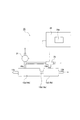
- FIG. 2 is a schematic diagram for explaining the configuration of the deaeration system according to the first embodiment.
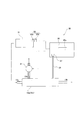
- FIG. 3 is a schematic diagram for explaining the configuration of the deaeration system according to the second embodiment.
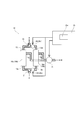
- FIG. 4 is a schematic diagram for explaining the configuration of the deaeration system according to the third embodiment.
- FIG. 1A and FIG. 1B are configuration diagrams for explaining the outline of a deaeration module constituting the deaeration system of the present invention.
- 10a is a degassing module
- 11 is a gas permeable degassing membrane
- 13a is an ink introduction path
- 13b is an ink outlet path
- 15 is a degassing chamber
- 15a is a case (frame body)
- 15b is an exhaust gas.
- An arrow A indicates the direction of ink flow
- an arrow B indicates the direction of gas flow.
- the gas permeable degassing film 11 is a film made of a functional material that does not allow ink to pass but only gas, and is formed of a bundle of films formed in a tube shape. is doing.
- the material for the deaeration membrane 11 include hollow fiber membranes and composite hollow fiber membranes having an appropriate inner diameter and film thickness, and various optimum materials can be selected depending on the application. For example, it is conceivable to use polymer materials such as polyolefin polymer, silicon rubber polymer, urethane polymer, and cellulose polymer. Further, the thickness and shape of the film may be determined according to conditions such as the material of the ink to be used and the required dissolved gas concentration in the ink. Furthermore, it is possible to select a single film or a multilayer structure. In the case of a multi-layer structure, a combination of different materials may be used.
- the ink introduction path 13a and the ink lead-out path 13b are provided to introduce ink into the degassing film 11 in the degassing chamber 15 and lead out the ink from the degassing film 11, and here, It consists of a tube shape.
- a material that does not contain a component that dissolves in the ink and does not deteriorate, deform, or break due to contact with the ink is preferable. Examples include polyolefin resins and acrylic resins.
- the deaeration chamber 15 includes a case (frame body) 15a surrounding the deaeration film 11 and a part of each of the ink introduction path 13a and the ink outlet path 13b.
- An exhaust port 15b is formed in a part of the case 15a.
- the deaeration membrane 11 is bonded to the case 15 a using an adhesive 16. More specifically, the outer peripheral surface of the deaeration membrane (hollow fiber membrane) 11 and the inner peripheral surface of the case 15a are bonded by the adhesive 16, and the end surface (end surface in the longitudinal direction) of the deaeration membrane (hollow fiber membrane) 11 ) Is open.
- an epoxy resin is used for the adhesive 16.
- the ink introduction path 13a and the deaeration film 11 are in close contact with each other, and the case 15a has a suitable shape such as a tube, a cube, a rectangular parallelepiped, or the like. Any shape can be used as long as it satisfies the function of the deaeration chamber 15, but any shape that can be mounted in the ink flow path closer to the head of the inkjet recording apparatus is close to the discharge nozzle of the head. This is more preferable because stable ink discharge can be expected.
- the material of the case 15a it is desirable to have an appropriate mechanical strength depending on the application. For example, in an operating state where the deaeration chamber 15 is decompressed to 5 kPa, it is desirable to have a strength that does not cause cracks, deformation, breakage, etc. that affect the function of the deaeration module 10. In addition, strength that does not cause an abnormality due to an operation such as scanning of the inkjet head is required. Examples of materials that satisfy these conditions include polyolefin resins and acrylic resins.
- the case 15a is required to contain no component that dissolves in the ink and does not deteriorate, deform, or break due to contact with the ink, like the ink introduction path 13a and the ink outlet path 13b.
- the case 15a is made of a material that does not transmit UV light (a material having a light shielding property).
- a material having a light shielding property For example, a colored polyethylene resin having a light-shielding property can be used.
- an organic electronic material in addition to an ink containing a color material for recording characters and images on a flat surface, an organic electronic material, a functional ink such as a dispersion ink of metal nanoparticles, and the like are included.
- the viscosity of the ink can be applied in the range of about 1 to 30 mPa ⁇ s, for example. Further, it is assumed that the temperature of the ink is in the range of 10 ° C. to 45 ° C. when the deaeration module 10a is operated, and that no abnormality occurs in the range of ⁇ 20 ° C. to 60 ° C. when not operating.
- 10b is a deaeration module having the same function as 10a.
- the deaeration film 11, the ink introduction path 13a, the ink outlet path 13b, the deaeration chamber 15, and the case 15a have the same functions as the deaeration module 10a in FIG. 1A, but are different in positional relationship.
- Arrow A indicates the direction of ink flow
- arrow B indicates the direction of gas flow.
- the ink introduction path 13a is not connected to the deaeration film 11, and is connected only to the case 15a. For this reason, the flow path of the ink introduced into the deaeration chamber 15 is outside the deaeration film 11 and inside the case 15a.
- the ink outlet path 13b is connected to a part of the case 15a.
- the exhaust port 15b passes through the case 15a and is connected to the deaeration membrane 11.
- the deaeration membrane 11 is bonded to the case 15 a using an adhesive 16.
- the outer peripheral surface of the degassing membrane (hollow fiber membrane) 11 near the exhaust port 15b and the inner peripheral surface of the case 15a are bonded by the adhesive 16, and the degassing membrane (hollow fiber membrane). 11 end face (end face in the longitudinal direction) near the exhaust port 15b is in an open state.
- the outer peripheral surface of the deaeration membrane (hollow fiber membrane) 11 near the ink introduction path 13a is bonded to the inner peripheral surface of the case 15a by the adhesive 16 together with the end surface (end surface in the longitudinal direction) near the ink introduction path 13a.
- an epoxy resin is used for the adhesive 16.
- the deaeration modules 10a and 10b are usually mounted inside the head carriage of an ink jet head in a printer.
- 1) Operation of the Deaeration Module 10a The ink flowing through the inkjet apparatus reaches the carriage of an inkjet head (not shown), and is removed from the deaeration chamber 15 from the means for supplying ink such as an ink tank through the ink introduction path 13a. It flows into the air membrane 11.
- the degassing membrane 11 is a bundle of tube-like membranes as described above, ink flows in the individual tubes of the degassing membrane.
- the inside of the deaeration chamber 15 is depressurized to about 5 kPa to 40 kPa by exhausting the gas in the deaeration chamber 15 to the outside from the exhaust port 15 b using a decompression means such as a vacuum pump described later.
- a decompression means such as a vacuum pump described later.
- the gas dissolved in the ink passing through the deaeration film 11 passes through the deaeration film 11 and is discharged into the deaeration chamber 15, thereby reducing the dissolved concentration of the gas in the ink.
- airtightness in the case 15a of the deaeration chamber 15 is ensured by the above-described exhaust treatment.
- the dissolved gas in the ink discharged into the deaeration chamber 15 is finally exhausted from the outside of the exhaust port 15b to the atmosphere via the decompression means. Thereafter, the ink from which the dissolved gas has been removed reaches the ink outlet path 13b, and further flows into the ink jet head. In this way, the degassed ink is sent into the ink jet head, and when ink is ejected from the head, it is ejected to the recording medium as ink having a low dissolved concentration of gas, and therefore mixed into the ink. It is possible to improve the accuracy of the image quality recorded on the recording medium without causing a discharge failure due to bubbles.
- the ink flowing through the ink jet recording apparatus reaches the carriage of the ink jet head (not shown), and supplies ink such as an ink tank through the ink introduction path 13a.
- the air flows into the inside of the case 15 a inside the deaeration chamber 15 and outside the deaeration membrane 11.
- the inside of the deaeration film 11 is depressurized to about 5 kPa to 40 kPa by exhausting the gas in the deaeration film 11 to the outside from the exhaust port 15b using a decompression means such as a vacuum pump described later.
- the gas dissolved in the ink passing outside the degassing film 11 passes through the degassing film 11 and is discharged in the direction of the exhaust port 15b, so that the dissolved concentration of the gas in the ink is reduced.
- the dissolved gas in the ink discharged into the degassing film 11 is finally exhausted from the outside of the exhaust port 15b to the atmosphere via the decompression means. Thereafter, the ink from which the dissolved gas has been removed reaches the ink outlet path 13b and further flows into the ink jet head.
- FIG. 2 is a schematic view of the deaeration system according to the first embodiment of the present invention.
- 10a (or 10b) is a deaeration module (FIGS. 1A and 1B), and two deaeration modules 10a (or 10b) and 10a (or 10b) are connected in series (hereinafter referred to as “deaeration module”).
- deaeration module 10a (10b) into which ink is introduced first is also referred to as a first deaeration module
- the deaeration module 10a (10b) into which ink is introduced next is also referred to as a second deaeration module).
- Reference numeral 13a denotes an ink introduction path which introduces ink into the deaeration chamber 15 (FIGS. 1A and 1B) of the deaeration module 10a (10b).
- Reference numeral 13 b denotes an ink outlet path that guides ink from the deaeration chamber 15. Further, the two degassing modules 10a (10b) are connected by a tube that also serves as the ink introduction path 13a and the ink outlet path 13b.
- Reference numeral 20 denotes a deaeration system according to the first embodiment
- reference numeral 21 denotes a pump (decompression unit) connected to the exhaust port 15 b of the deaeration chamber 15.
- a diaphragm type vacuum pump is used.
- the gas deaerated by the pump 21 passes through the pump 21 and is then exhausted to the atmosphere.
- the direction of exhaust is indicated by an arrow for convenience.
- Reference numeral 23 denotes a three-way valve, which is connected between the pressure reducing device 21 and the exhaust port 15 of the deaeration module 10 a (10 b) in which the ink flows in the second order.
- Reference numeral 25 denotes a control unit, and 25a denotes a memory.
- the control unit 25 selects a deaeration method corresponding to a plurality of types of ink stored in the memory 25a.
- the selected information is transmitted to the pump 21 and the three-way valve 23, and the pump 21 exhausts from the exhaust port 15b of only the first degassing module 10a based on the degassing method, or the first And the gas dissolved in the ink in the deaeration chamber of each deaeration module is degassed by continuously exhausting outside from the exhaust ports 15b and 15b of the second deaeration module 10a (10b). To do.
- the operator identifies the type of ink and sends an instruction to the control unit 25 by selecting a degassing method corresponding to a plurality of types of ink from the memory 25a by an input operation to the panel.
- the control unit 25 controls the driving of the three-way valve 23 and the driving of the pump 21 based on the selected degassing method.
- the three-way valve 23 changes its direction to either the left or right.
- the three-way valve 23 is driven in a direction in which the exhaust port 15b of the second degassing module 10a (10b) and the pump 21 are connected (hereinafter, this direction is referred to as the left direction for convenience)
- this direction is referred to as the left direction for convenience
- the gas in the first and second degassing modules 10a and 10b can be exhausted by the pump 21
- Degassing is performed by the second degassing module 10a (10b), and two-stage degassing can be performed.
- the ink is once degassed by the first degassing module 10a (10b), and then from the pump 21 in the second degassing module 10a (10b). Since no exhaust is performed, it only passes. Furthermore, it is possible to set so that the pump 21 does not exhaust at all and the two deaeration modules 10a (10b) only allow ink to pass through.
- the deaeration system of the first embodiment it is possible to select and perform a deaeration method corresponding to a plurality of types of ink, in this case, the deaeration of three levels of strength. Thus, it is possible to control the rate of deaeration of ink, that is, how much deaeration is performed.
- the first and second degassing modules are not the same, and may have different degassing capabilities. For example, if the degassing membrane of one degassing module is long (large), a difference occurs in the degassing ability of both degassing modules.
- the combination (a combination of degassing modules having different degassing capabilities) can also be adopted according to the type of ink.
- degassing is not performed for the following reasons when a cleaning liquid is used instead of ink. That is, since the cleaning liquid itself does not generate bubbles, degassing is unnecessary. Further, since a liquid containing a solvent having a relatively low boiling point is allowed to flow as the cleaning liquid, the solvent permeates the degassing membrane 11 and flows out from the exhaust port 15b, which may cause a failure of the pump 21.
- FIG. 3 27 is an atmospheric pressure sensor (pressure sensor), and 29 is a pressure detection tube.
- the atmospheric pressure sensor 27 is connected to the deaeration module 10a (10b) through the pressure detection tube 29, and the pressure in the deaeration chamber 15 (FIGS. 1A and 1B) of the deaeration module 10a (10b) is measured by the atmospheric pressure sensor 27. It can be detected by.
- Reference numeral 31 denotes an ink tank which performs deaeration by sending ink to the deaeration module 10a (10b).
- Reference numeral 33 denotes ink identification means for identifying the type of ink in the ink tank 31.
- the ink identification unit 33 includes an IC chip 33a in which the ink type is recorded, and a reading sensor 33b that reads data on the ink type recorded in the IC chip 33a. Since the other configuration is the same as that of the deaeration system 20 of the first embodiment, detailed description thereof is omitted.
- the reading sensor 33b reads the ink type data recorded on the IC chip 33a provided in the ink tank 31, and the data is output to the control unit 25. This data is also transmitted to the memory 25a.
- the memory 25a stores a deaeration method corresponding to a plurality of types of ink.
- the memory 25 a stores a pressure value in the deaeration chamber corresponding to the type of ink, and outputs this pressure value to the control unit 25.
- the atmospheric pressure sensor 27 detects the pressure in the deaeration chamber 15 via the pressure detection tube 29, is converted into pressure data, and is input to the control unit 25.
- the control unit 25 compares the pressure value output from the memory with the pressure value in the deaeration chamber detected by the atmospheric pressure sensor 27, and drives the pump 21 to further exhaust or stop driving.
- the pressure in the deaeration chamber 15 is controlled to be a predetermined optimum value.
- the number of types of ink can be set to an arbitrary number by the ink identification means 33 and the memory 25a.
- the ink identification means 33 and the memory 25a For example, although one ink flow path is shown in FIG. 3, four color ink flow paths of Y (yellow), M (magenta), C (cyan), and K (black) can be controlled simultaneously.
- four degassing modules 10a (10b), four atmospheric pressure sensors 27, and four reading sensors 33b are arranged, and an electromagnetic opening / closing valve is further arranged between the pump 21 and the exhaust ports 15b of the four degassing modules.
- the memory 25a can store the data of the deaeration method (here, the pressure value described above) corresponding to a plurality of types of ink in the plurality of ink flow paths described above.
- FIG. 4 is a schematic view of a deaeration system 40 according to the third embodiment of the present invention.
- the deaeration system 40 according to the present embodiment has a configuration in which two deaeration modules 10a (or 10b) and 10a (or 10b) are connected in parallel. It differs from the deaeration system 20 which concerns on a form.
- one of the two degassing modules connected in parallel here, the left degassing module 10a (or 10b) in FIG. 4) is referred to as the first degassing module, and the other (here, The right degassing module 10a (or 10b) in FIG. 4 is referred to as a second degassing module (they may be reversed).
- omitted since it has already demonstrated about the structure of deaeration module 10a, 10b, repeated description is abbreviate
- omitted since it has already demonstrated about the structure of deaeration module 10a, 10b, repeated description is abbreviate
- 13a is an ink introduction path, which introduces ink into the deaeration chamber 15 (see FIGS. 1A and 1B) of each deaeration module 10a (10b).
- Reference numeral 13 b denotes an ink outlet path that guides ink from the deaeration chamber 15.
- the two degassing modules 10a (10b) and 10a (10b) are connected by a tube that also serves as the ink introduction path 13a and a tube that also serves as the ink outlet path 13b.
- Reference numeral 21 denotes a pump (decompression unit) connected to the exhaust port 15 b of the deaeration chamber 15.
- a diaphragm type vacuum pump is used. The gas deaerated by the pump 21 passes through the pump 21 and is then exhausted to the atmosphere. The direction of exhaust is indicated by arrow B for convenience.
- Reference numeral 24 denotes an electromagnetic valve used as an on-off valve.
- a solenoid valve 24 (24a) is provided between S1 and the second degassing module 10a (10b), and is on the path of the ink outlet path 13b (second) from the second degassing module 10a (10b).
- a solenoid valve 24 (24b) is provided between the first deaeration module 10a (10b) and the junction S2.
- either one of the electromagnetic valves 24a and 24b is replaced with a check valve or omitted (not shown).
- Reference numeral 25 denotes a control unit, and 25a denotes a memory.
- the control unit 25 selects a deaeration method corresponding to a plurality of types of ink stored in the memory 25a.
- the selected information is transmitted to the pump 21 and the solenoid valves 24 (24a, 24b), and the pump 21 exhausts from the exhaust port 15b of only the first degassing module 10a (10b) based on the degassing method. Or by exhausting outside from the exhaust ports 15b and 15b of the first and second deaeration modules 10a (10b) and 10a (10b), the deaeration chambers of the respective deaeration modules The gas dissolved in the ink is degassed.
- the operator identifies the type of ink and sends an instruction to the control unit 25 by selecting a degassing method corresponding to a plurality of types of ink from the memory 25a by an input operation to the panel.
- the control unit 25 controls the driving of the electromagnetic valves 24 a and 24 b and the driving of the pump 21 based on the selected degassing method.
- the electromagnetic valves 24a and 24b are opened and closed.
- the ink is deaerated by the two deaeration modules 10a (10b) and 10a (10b).
- the degassing process flow rate increases if the pressure is the same, and degassing can be strengthened if the process flow rate is the same. An effect is obtained.
- the pump is driven to close the solenoid valves 24a and 24b, the ink is deaerated by the single deaeration module 10a (10b). In this way, two-stage deaeration can be performed by opening and closing the electromagnetic valves 24a and 24b. Further, it is possible to set so that the pump 21 is not exhausted at all and the two degassing modules 10a (10b) and 10a (10b) only pass ink and do not degas.
- the deaeration system 40 it is possible to select and perform a deaeration method corresponding to a plurality of types of ink, in this case, three levels of deaeration, Thereby, it is possible to control the rate of deaeration of ink, that is, how much deaeration is performed.
- the two degassing modules 10a (or 10b) and 10a (or 10b) are not the same and may have different degassing capabilities. For example, if the degassing membrane of one degassing module is long (large), a difference occurs in the degassing ability of both degassing modules.
- the combination (a combination of degassing modules having different degassing capabilities) can also be adopted according to the type of ink.
- the deaeration system of the present invention even when a plurality of types of ink are used in the same apparatus, it is possible to perform the optimum deaeration according to the characteristics of each ink. it can. Therefore, the ink ejection stability of the ink jet recording apparatus can be ensured, and the image quality of the recording medium can be maintained with high accuracy.
- the present invention is not limited to the above-described embodiment.
- the number of deaeration modules is not limited to two in either case where a plurality of deaeration modules are connected in series or a plurality of deaeration modules are connected in parallel.
- the deaeration modules 10a and 10b are not necessarily used in a unified manner.
- the ink identification unit 33 includes the IC chip 33a and the reading sensor 33b.
- a combination of a barcode and a reading sensor may be used.
- suitable various materials constituting the deaeration module have been described.
- the present invention is not limited thereto, and various suitable materials can be used.
- the present invention is not limited to the ink to be used, the type and form of the recording medium, the head ejection method, and the like.
- various modifications can be made without departing from the spirit of the invention.
Landscapes
- Ink Jet (AREA)
Abstract
同じ装置において、使用するインクの種類を切り替えても、インクに応じた脱気を行うことが可能な脱気システムを提供することを課題とする。 解決手段として、気体透過性を有する脱気膜11と、脱気膜11を内包する枠体15a内に構成される脱気室15と、脱気室15へのインクの導入を行うインク導入路13a及び脱気室15からインクを導出するインク導出路13bと、枠体15aの一部に脱気室15内の気体を外部に排気するための排気口15bとを備えた脱気モジュール10a(10b)と、排気口に接続されて排気を行う減圧手段21と、複数の種類のインクに応じた脱気方法を記憶したメモリ25aを備えた制御部25とを備え、脱気室15に導入するインクの種類に応じてメモリ25aに記憶された脱気方法を選択し、減圧手段21は制御部25により選択された脱気方法に基づいて排気口15bから脱気膜11を透過する気体を外部に排気することにより脱気室15内のインク中に溶存する気体を脱気するように、脱気システム20を構成する。
Description
本発明は、インクジェット記録装置用のインク中に溶存する気体を取り除く脱気システムに関する。
インクジェットプリンタ等、被記録体にインクを吐出して着弾することによりパターン記録を行う記録装置において、インク中に溶存する気体がインクジェットヘッドからインクを吐出する過程で気泡に成長することがある。これが原因となり、インクの不吐出やいわゆる飛行曲がり等のインクの吐出不良を招くことがあるため、被記録体への記録画像の精度保持の点で問題となっていた。インクの吐出の安定を図るためには、インクジェットヘッドに供給するインク中の溶存気体を除去することが必要である。そこで、インクジェット記録装置において、インクジェットヘッドのインク供給経路の途中に脱気装置を組み込み、インク中の溶存気体を取り除く構成のものが公知である。
例えば特許文献1には、上記のような構成を備えたインクジェット記録装置として、インク供給経路に脱気装置が備えられたものが開示されている。
また、特許文献2には気体透過性のある膜を介してインクの溶存気体を外部へ透過させることにより除去する方法であって、ある基準以上の脱気処理を行うため、一つの脱気装置内に二つ以上の脱気エレメントを接続して脱気する方法が開示されている。
例えば特許文献1には、上記のような構成を備えたインクジェット記録装置として、インク供給経路に脱気装置が備えられたものが開示されている。
また、特許文献2には気体透過性のある膜を介してインクの溶存気体を外部へ透過させることにより除去する方法であって、ある基準以上の脱気処理を行うため、一つの脱気装置内に二つ以上の脱気エレメントを接続して脱気する方法が開示されている。
しかしながら、上述の特許文献1に開示されたインクジェット記録装置や特許文献2に開示された脱気方法では、以下に示すような課題があった。
インクジェット記録装置において、使用するインクの種類を1種類に限定せず、同じ装置でも複数種類のインクを必要に応じて切り替えて使用する場合がある。例えば、反応染料インクと酸性染料インクを必要に応じて切り替えて使用する場合、同様に水性染料インクと水性顔料インク、水性インクと溶剤インク、昇華転写インクと溶剤インク、透明インクと白インク等を必要に応じて切り替えて使用する場合が考えられる。また、硬化後の硬さの異なるUVインク間での切り替えなども考えられる。
このように同じ装置で複数の種類のインクを使用する場合、使用するインクの種類を切り替えて装置を動作させた場合には、インクの吐出の安定性を確保できず、吐出不良を招くという課題があった。これは、使用するインク毎に、要求される脱気レベル(脱気の強さ)が異なるためである。
例えば低沸点の溶剤成分を含むインクの場合、強すぎる脱気を行うと、脱気した気体と共に溶剤が失われてインクの粘度が上がってしまう。また、UVインク(紫外線硬化型インク)の場合も同様に強すぎる脱気を行うと、脱気が行われた時点からインクの硬化が進んでしまう。したがって、インクの脱気処理においては、インク毎の特性に応じた最適なレベルとすることが必要であるといえる。
本発明は以上の点を鑑み、インクジェット記録装置において、使用するインクの種類が複数に及ぶ場合であっても、それぞれのインクの特性に応じた最適な脱気を行うことが可能な脱気システムを提供しようとするものである。
インクジェット記録装置において、使用するインクの種類を1種類に限定せず、同じ装置でも複数種類のインクを必要に応じて切り替えて使用する場合がある。例えば、反応染料インクと酸性染料インクを必要に応じて切り替えて使用する場合、同様に水性染料インクと水性顔料インク、水性インクと溶剤インク、昇華転写インクと溶剤インク、透明インクと白インク等を必要に応じて切り替えて使用する場合が考えられる。また、硬化後の硬さの異なるUVインク間での切り替えなども考えられる。
このように同じ装置で複数の種類のインクを使用する場合、使用するインクの種類を切り替えて装置を動作させた場合には、インクの吐出の安定性を確保できず、吐出不良を招くという課題があった。これは、使用するインク毎に、要求される脱気レベル(脱気の強さ)が異なるためである。
例えば低沸点の溶剤成分を含むインクの場合、強すぎる脱気を行うと、脱気した気体と共に溶剤が失われてインクの粘度が上がってしまう。また、UVインク(紫外線硬化型インク)の場合も同様に強すぎる脱気を行うと、脱気が行われた時点からインクの硬化が進んでしまう。したがって、インクの脱気処理においては、インク毎の特性に応じた最適なレベルとすることが必要であるといえる。
本発明は以上の点を鑑み、インクジェット記録装置において、使用するインクの種類が複数に及ぶ場合であっても、それぞれのインクの特性に応じた最適な脱気を行うことが可能な脱気システムを提供しようとするものである。
上述した本発明の目的を達成するために、本発明による脱気システムは、以下の1~4に示すように構成される。
1)気体透過性を有する脱気膜と、脱気膜を内包する枠体内に構成される脱気室と、脱気室へのインクの導入を行うインク導入路及び脱気室からインクを導出するインク導出路と、枠体の一部に脱気室内の気体を外部に排気するための排気口とを備えた脱気モジュール。
2)排気口に接続されて排気を行う減圧手段。
3)複数の種類のインクに応じた脱気方法を記憶したメモリを備えた制御部。
4)上記の1~3を備え、脱気室に導入するインクの種類に応じてメモリに記憶された脱気方法を選択し、減圧手段は制御部により選択された脱気方法に基づいて排気口から脱気膜を透過する気体を外部に排気することにより、脱気室内のインク中に溶存する気体を脱気する。
また、インク導入路に接続されてこのインク導入路にインクを送るインクタンクと、インクタンク中のインクの種類を識別するインク識別手段とをさらに備え、上述の制御部は、識別手段の識別結果に基づいて脱気方法を選択するようにすると良い。
また、上述の脱気方法は、脱気モジュールを複数個直列に接続して、二つ目以降の脱気モジュールの、脱気室に導入するインクから排気を行うか否かを選択することにより、脱気を行う割合を段階的に制御する方法とするのが良い。
あるいは、上述の脱気方法を、制御部が脱気室に接続されてこの脱気室内の圧力を検知する圧力センサをさらに備え、脱気室内の圧力の大きさが所定の値となるように排気の駆動を制御する方法としても良い。
なお、本発明で述べるインクとは、文字や画像を平面上に記録する色材を含むインクや、有機エレクトロニクス材料、金属ナノ粒子の分散インク等の機能性インク等を含んでいる。
1)気体透過性を有する脱気膜と、脱気膜を内包する枠体内に構成される脱気室と、脱気室へのインクの導入を行うインク導入路及び脱気室からインクを導出するインク導出路と、枠体の一部に脱気室内の気体を外部に排気するための排気口とを備えた脱気モジュール。
2)排気口に接続されて排気を行う減圧手段。
3)複数の種類のインクに応じた脱気方法を記憶したメモリを備えた制御部。
4)上記の1~3を備え、脱気室に導入するインクの種類に応じてメモリに記憶された脱気方法を選択し、減圧手段は制御部により選択された脱気方法に基づいて排気口から脱気膜を透過する気体を外部に排気することにより、脱気室内のインク中に溶存する気体を脱気する。
また、インク導入路に接続されてこのインク導入路にインクを送るインクタンクと、インクタンク中のインクの種類を識別するインク識別手段とをさらに備え、上述の制御部は、識別手段の識別結果に基づいて脱気方法を選択するようにすると良い。
また、上述の脱気方法は、脱気モジュールを複数個直列に接続して、二つ目以降の脱気モジュールの、脱気室に導入するインクから排気を行うか否かを選択することにより、脱気を行う割合を段階的に制御する方法とするのが良い。
あるいは、上述の脱気方法を、制御部が脱気室に接続されてこの脱気室内の圧力を検知する圧力センサをさらに備え、脱気室内の圧力の大きさが所定の値となるように排気の駆動を制御する方法としても良い。
なお、本発明で述べるインクとは、文字や画像を平面上に記録する色材を含むインクや、有機エレクトロニクス材料、金属ナノ粒子の分散インク等の機能性インク等を含んでいる。
また、本発明において、前記脱気方法は、前記脱気モジュールを複数個並列に接続して、2つ目以降の前記脱気モジュールの、前記脱気室に導入するインクから前記排気を行うか否かを選択することにより、脱気を行う割合を段階的に制御する方法であることが好ましい。その場合、前記2つ目以降の脱気モジュールの前記インク導入路もしくは前記インク導出路の少なくとも一方に開閉弁を備え、前記脱気室に導入するインクから前記排気を行うか否かの選択に基づいて前記開閉弁を開閉することが好ましい。
これによれば、複数の種類のインクに応じて、段階的な強さの脱気方法を選択して行うことが可能となり、これによりインクの脱気の割合、すなわちどのくらい脱気を行うかの程度を制御することが可能となる。
これによれば、複数の種類のインクに応じて、段階的な強さの脱気方法を選択して行うことが可能となり、これによりインクの脱気の割合、すなわちどのくらい脱気を行うかの程度を制御することが可能となる。
本発明の脱気システムは、インクジェット記録装置において、使用するインクの種類が複数に及ぶ場合であっても、それぞれのインクの特性に応じた最適な脱気を行うことを可能としている。このため、インクジェット記録装置のインクの吐出の安定性を確保することができる。したがって、被記録体の画質を高精度に保つこともできる。
以下、本発明を実施するための形態を図示例と共に説明する。なお、実施形態を説明するための全図において、同一の機能を有する部材には同一の符号を付し、その繰り返しの説明は省略する場合がある。
図1A及び図1Bは、本発明の脱気システムを構成する脱気モジュールの概要を説明するための構成図である。
図1Aにおいて、10aは脱気モジュール、11は気体透過性を有する脱気膜、13aはインク導入路、13bはインク導出路、15は脱気室、15aはケース(枠体)、15bは排気口である。また、矢印Aはインクの流れる向きを、矢印Bは気体の流れる向きを示す。
図1A及び図1Bは、本発明の脱気システムを構成する脱気モジュールの概要を説明するための構成図である。
図1Aにおいて、10aは脱気モジュール、11は気体透過性を有する脱気膜、13aはインク導入路、13bはインク導出路、15は脱気室、15aはケース(枠体)、15bは排気口である。また、矢印Aはインクの流れる向きを、矢印Bは気体の流れる向きを示す。
気体透過性を有する脱気膜11は、インクを通過させず、気体のみを通過させる機能性材料からなる膜であり、ここではチューブ状に形成された膜が束になった形状のもので構成している。
脱気膜11の材料としては、適切な内径や膜厚を有する中空糸膜、複合中空糸膜等が挙げられ、用途によって種々最適なものを選択することができる。例えば、ポリオレフィン系ポリマー、シリコンゴム系ポリマー、ウレタン系ポリマー、セルロース系ポリマー等のポリマー素材等を用いることが考えられる。
また、用いるインクの材質、要求されるインク中の溶存気体濃度等の条件により、膜の厚さや形状を決定すると良い。さらに、膜を単一で用いたり、多層構造にしたりする等の選択も可能である。多層構造にする場合、異種の素材の組み合わせを用いて構成しても良い。
脱気膜11の材料としては、適切な内径や膜厚を有する中空糸膜、複合中空糸膜等が挙げられ、用途によって種々最適なものを選択することができる。例えば、ポリオレフィン系ポリマー、シリコンゴム系ポリマー、ウレタン系ポリマー、セルロース系ポリマー等のポリマー素材等を用いることが考えられる。
また、用いるインクの材質、要求されるインク中の溶存気体濃度等の条件により、膜の厚さや形状を決定すると良い。さらに、膜を単一で用いたり、多層構造にしたりする等の選択も可能である。多層構造にする場合、異種の素材の組み合わせを用いて構成しても良い。
インク導入路13a及びインク導出路13bは、脱気室15内の脱気膜11へのインクの導入及び脱気膜11からのインクの導出を行うために設けられているものであり、ここではチューブ形状のもので構成している。インク導入路13a及びインク導出路13bの材料としては、インク中に溶解する成分を含まず、インクとの接触により変質、変形、破損しないものが好適である。例として、ポリオレフィン系樹脂、アクリル系樹脂が挙げられる。
脱気室15は、脱気膜11と、インク導入路13a及びインク導出路13bのそれぞれの一部とを取り囲むケース(枠体)15aで構成され、このケース15aの一部に排気口15bを備えている。
ここで、脱気膜11は接着剤16を用いてケース15aに接着されている。より詳しくは、脱気膜(中空糸膜)11の外周面とケース15aの内周面とが接着剤16によって接着されており、脱気膜(中空糸膜)11の端面(長手方向の端面)は開放された状態となっている。一例として、接着剤16にはエポキシ系樹脂が用いられる。
ここで、脱気膜11は接着剤16を用いてケース15aに接着されている。より詳しくは、脱気膜(中空糸膜)11の外周面とケース15aの内周面とが接着剤16によって接着されており、脱気膜(中空糸膜)11の端面(長手方向の端面)は開放された状態となっている。一例として、接着剤16にはエポキシ系樹脂が用いられる。
脱気モジュール10aの場合は、インク導入路13aと脱気膜11とが密接しており、ケース15aは、管体や立方体、直方体等の、用途に応じた好適な形状のものとする。どのような形状であっても、脱気室15の機能を満足するものであれば良いが、インクジェット記録装置のヘッドにより近いインク流路に実装可能な形状であれば、ヘッドの吐出ノズルに近く安定したインクの吐出が望めるため、より好ましい。
ケース15aの材料については、用途に応じて適当な機械的強度を有するものが望ましい。例えば、脱気室15を5kPaに減圧した稼動状態において、脱気モジュール10の機能に影響するクラックや変形、破損等が発生しない強度を有することが望ましい。また、インクジェットヘッドの走査等の動作による異常が発生しない強度が要求される。これらの条件を満たす材料としては、ポリオレフィン系樹脂、アクリル系樹脂等が挙げられる。
また、ケース15aにおいては、インク導入路13a及びインク導出路13bと同様に、インク中に溶解する成分を含まず、インクとの接触により変質、変形、破損しないことが要求される。また、UV硬化性のインクを用いる場合、ケース15aはUV光が透過しない材料(遮光性を有する材料)で構成する。例えば、遮光性を有する着色ポリエチレン樹脂等が挙げられる。
使用するインクについて、本発明においては、文字や画像を平面上に記録する色材を含むインクの他、有機エレクトロニクス材料、金属ナノ粒子の分散インク等の機能性インク等を含んでいる。
インクの粘度は、例えば1~30mPa・s程度の範囲で適用可能である。また、脱気モジュール10aの稼動時には、インクの温度が10℃から45℃の範囲であり、また非稼動時には-20℃から60℃の範囲で異常発生がないことを前提としている。
インクの粘度は、例えば1~30mPa・s程度の範囲で適用可能である。また、脱気モジュール10aの稼動時には、インクの温度が10℃から45℃の範囲であり、また非稼動時には-20℃から60℃の範囲で異常発生がないことを前提としている。
次に、図1Bにおいて、10bは10aと同様の機能を有する脱気モジュールである。脱気膜11、インク導入路13a、インク導出路13b、脱気室15、ケース15aは図1Aの脱気モジュール10aと同様の機能を有するが、位置関係が異なっている。矢印Aはインクの流れる向きを、矢印Bは気体の流れる向きを示す。
脱気モジュール10bは、インク導入路13aが脱気膜11とは接続されておらず、ケース15aのみに接続されている。このため、脱気室15内に導入されたインクの流路は、脱気膜11の外側であって、ケース15aの内側である。また、インク導出路13bも同様に、ケース15aの一部に接続されている。排気口15bはケース15aを貫通して脱気膜11に接続されている。
脱気モジュール10bは、インク導入路13aが脱気膜11とは接続されておらず、ケース15aのみに接続されている。このため、脱気室15内に導入されたインクの流路は、脱気膜11の外側であって、ケース15aの内側である。また、インク導出路13bも同様に、ケース15aの一部に接続されている。排気口15bはケース15aを貫通して脱気膜11に接続されている。
また、脱気膜11は接着剤16を用いてケース15aに接着されている。本実施形態においては、脱気膜(中空糸膜)11の排気口15b寄りの外周面とケース15aの内周面とが接着剤16によって接着されており、当該脱気膜(中空糸膜)11の排気口15b寄りの端面(長手方向の端面)は開放された状態となっている。一方、脱気膜(中空糸膜)11のインク導入路13a寄りの外周面は当該インク導入路13a寄りの端面(長手方向の端面)と共に接着剤16によってケース15aの内周面に接着されており、当該脱気膜(中空糸膜)11のインク導入路13a寄りの端面は開放されていない状態となっている。一例として、接着剤16にはエポキシ系樹脂が用いられる。
次に、脱気モジュール10a及び10bの動作につき説明をする。
脱気モジュール10a及び10bは、通常、プリンターにおける、インクジェットヘッドのヘッドキャリッジ内部に実装されるものとする。
1)脱気モジュール10aの動作
インクジェット装置を流れるインクは、図示しないインクジェットヘッドのキャリッジ内に到達し、インクタンク等のインクを供給する手段からインク導入路13aを介し、脱気室15内の脱気膜11内に流れ込む。詳細には、脱気膜11は前述のようにチューブ状の膜の束であるため、脱気膜の個々のチューブ内をインクが流れることになる。このとき、脱気室15内の気体を、例えば後述する真空ポンプ等の減圧手段を用いて排気口15bから外部に排気させることにより、脱気室15内を5kPa~40kPa程度に減圧する。これにより、脱気膜11内を通過するインク内に溶存する気体が、脱気膜11を透過して脱気室15内に排出され、インク中の気体の溶存濃度が低減される。また同時に、上述の排気処理により、脱気室15のケース15a内の気密性が確保される。脱気室15内に排出されたインク中の溶存気体は、最終的には排気口15bの外側から、減圧手段を経由して大気中に排気される。その後、溶存気体が除かれたインクがインク導出路13bに到達し、さらにインクジェットヘッド内部へと流れ込む。
このように、インクジェットヘッド内部へ脱気されたインクが送られ、ヘッドからインクを吐出する際には気体の溶存濃度が低いインクとなって被記録体に吐出されるため、インク中に混入する気泡に起因した吐出不良が発生することもなく、被記録体に記録される画質の精度を向上させることができる。
脱気モジュール10a及び10bは、通常、プリンターにおける、インクジェットヘッドのヘッドキャリッジ内部に実装されるものとする。
1)脱気モジュール10aの動作
インクジェット装置を流れるインクは、図示しないインクジェットヘッドのキャリッジ内に到達し、インクタンク等のインクを供給する手段からインク導入路13aを介し、脱気室15内の脱気膜11内に流れ込む。詳細には、脱気膜11は前述のようにチューブ状の膜の束であるため、脱気膜の個々のチューブ内をインクが流れることになる。このとき、脱気室15内の気体を、例えば後述する真空ポンプ等の減圧手段を用いて排気口15bから外部に排気させることにより、脱気室15内を5kPa~40kPa程度に減圧する。これにより、脱気膜11内を通過するインク内に溶存する気体が、脱気膜11を透過して脱気室15内に排出され、インク中の気体の溶存濃度が低減される。また同時に、上述の排気処理により、脱気室15のケース15a内の気密性が確保される。脱気室15内に排出されたインク中の溶存気体は、最終的には排気口15bの外側から、減圧手段を経由して大気中に排気される。その後、溶存気体が除かれたインクがインク導出路13bに到達し、さらにインクジェットヘッド内部へと流れ込む。
このように、インクジェットヘッド内部へ脱気されたインクが送られ、ヘッドからインクを吐出する際には気体の溶存濃度が低いインクとなって被記録体に吐出されるため、インク中に混入する気泡に起因した吐出不良が発生することもなく、被記録体に記録される画質の精度を向上させることができる。
2)脱気モジュール10bの動作
脱気モジュール10aと同様、インクジェット記録装置を流れるインクが、図示しないインクジェットヘッドのキャリッジ内に到達し、インクタンク等のインクを供給する手段からインク導入路13aを介し、脱気室15内の、ケース15aの内側であって、脱気膜11の外側の部分に流れ込む。このとき、脱気膜11内の気体を、後述する真空ポンプ等の減圧手段を用いて排気口15bから外部に排気させることにより、脱気膜11内を5kPa~40kPa程度に減圧する。これにより、脱気膜11の外側を通過するインク内に溶存する気体が、脱気膜11を透過して排気口15b方向に排出され、インク中の気体の溶存濃度が低減される。脱気膜11内に排出されたインク中の溶存気体は、最終的には排気口15bの外側から、減圧手段を経由して大気中に排気される。その後、溶存気体が除かれたインクがインク導出路13bに到達し、さらにインクジェットヘッド内部へと流れ込む。
脱気モジュール10aと同様、インクジェット記録装置を流れるインクが、図示しないインクジェットヘッドのキャリッジ内に到達し、インクタンク等のインクを供給する手段からインク導入路13aを介し、脱気室15内の、ケース15aの内側であって、脱気膜11の外側の部分に流れ込む。このとき、脱気膜11内の気体を、後述する真空ポンプ等の減圧手段を用いて排気口15bから外部に排気させることにより、脱気膜11内を5kPa~40kPa程度に減圧する。これにより、脱気膜11の外側を通過するインク内に溶存する気体が、脱気膜11を透過して排気口15b方向に排出され、インク中の気体の溶存濃度が低減される。脱気膜11内に排出されたインク中の溶存気体は、最終的には排気口15bの外側から、減圧手段を経由して大気中に排気される。その後、溶存気体が除かれたインクがインク導出路13bに到達し、さらにインクジェットヘッド内部へと流れ込む。
次に、図2を用いて第1の実施の形態の脱気システムにつき説明をする。図2は本発明の第1の実施の形態の脱気システムの概略図である。
図2において、10a(または10b)は、脱気モジュール(図1A及び図1B)であり、二つの脱気モジュール10a(または10b)及び10a(または10b)が、直列に接続されている(以下、インクが先に導入される脱気モジュール10a(10b)を一つ目の脱気モジュール、次に導入される脱気モジュール10a(10b)を二つ目の脱気モジュールともいう)。10a(10b)の構成については、既に説明してあるため、詳しい説明を省略する。13aはインク導入路であり、脱気モジュール10a(10b)の脱気室15(図1A及び図1B)内にインクを導入する。13bはインク導出路であり、脱気室15からインクを導出する。また、二つの脱気モジュール10a(10b)間は、インク導入路13a及びインク導出路13bを兼ねたチューブで接続されている。
図2において、10a(または10b)は、脱気モジュール(図1A及び図1B)であり、二つの脱気モジュール10a(または10b)及び10a(または10b)が、直列に接続されている(以下、インクが先に導入される脱気モジュール10a(10b)を一つ目の脱気モジュール、次に導入される脱気モジュール10a(10b)を二つ目の脱気モジュールともいう)。10a(10b)の構成については、既に説明してあるため、詳しい説明を省略する。13aはインク導入路であり、脱気モジュール10a(10b)の脱気室15(図1A及び図1B)内にインクを導入する。13bはインク導出路であり、脱気室15からインクを導出する。また、二つの脱気モジュール10a(10b)間は、インク導入路13a及びインク導出路13bを兼ねたチューブで接続されている。
20は、第1の実施の形態の脱気システムであり、21は、脱気室15の排気口15bに接続されたポンプ(減圧手段)である。ここではダイアフラム型の真空ポンプを用いるものとする。ポンプ21により脱気された気体は、ポンプ21を経由した後、大気中に排気される。排気される方向を便宜的に矢印で示した。23は三方弁であり、ここではインクの流れる順番が2番目となる脱気モジュール10a(10b)の排気口15と、減圧装置21との間に接続されている。また、25は制御部、25aはメモリである。制御部25はメモリ25aに記憶された複数の種類のインクに応じた脱気方法を選択する。選択された情報は、ポンプ21及び三方弁23に伝えられ、ポンプ21はその脱気方法に基づいて、一つ目の脱気モジュール10aのみの排気口15bから排気を行う、あるいは、一つ目及び二つ目の脱気モジュール10a(10b)の排気口15b、15bから、連続して外部に排気を行うことにより、それぞれの脱気モジュールの脱気室内のインク中に溶存する気体を脱気する。
複数の種類のインクを認識し、メモリ25aに記憶された脱気方法からインクに応じた脱気方法を選択し、選択した脱気方法の指示を制御部25へ送るのは、ここでは人が行うことを想定している。
複数の種類のインクを認識し、メモリ25aに記憶された脱気方法からインクに応じた脱気方法を選択し、選択した脱気方法の指示を制御部25へ送るのは、ここでは人が行うことを想定している。
次に、第1の実施の形態の脱気システム20の動作につき説明をする。
操作者がインクの種類を識別し、メモリ25aから複数種類のインクに応じた脱気方法をパネルへの入力操作によって選択することにより、制御部25へ指示を送る。制御部25は、選択された脱気方法に基づいて、三方弁23の駆動、及びポンプ21の駆動を制御する。制御部25からの指示により、三方弁23は左右いずれかに向きを変える。例えば二つ目の脱気モジュール10a(10b)の排気口15bとポンプ21とが接続される方向(以下、この方向を便宜的に左方向という)に三方弁23が駆動されると、一つ目及び二つ目の脱気モジュール10a及び10b内の気体は、どちらもポンプ21によって排気することができるため、一つ目の脱気モジュール10a(10b)を経て脱気されたインクが、再び二つ目の脱気モジュール10a(10b)で脱気されることとなり、2段階の脱気を行うことができる。
操作者がインクの種類を識別し、メモリ25aから複数種類のインクに応じた脱気方法をパネルへの入力操作によって選択することにより、制御部25へ指示を送る。制御部25は、選択された脱気方法に基づいて、三方弁23の駆動、及びポンプ21の駆動を制御する。制御部25からの指示により、三方弁23は左右いずれかに向きを変える。例えば二つ目の脱気モジュール10a(10b)の排気口15bとポンプ21とが接続される方向(以下、この方向を便宜的に左方向という)に三方弁23が駆動されると、一つ目及び二つ目の脱気モジュール10a及び10b内の気体は、どちらもポンプ21によって排気することができるため、一つ目の脱気モジュール10a(10b)を経て脱気されたインクが、再び二つ目の脱気モジュール10a(10b)で脱気されることとなり、2段階の脱気を行うことができる。
また、三方弁23の向きを右方向とすると、インクは一つ目の脱気モジュール10a(10b)で一度脱気された後、二つ目の脱気モジュール10a(10b)においてはポンプ21からの排気が行われないため、通過するのみとなる。
さらに、ポンプ21からの排気を全く行わず、二つの脱気モジュール10a(10b)ともインクを通過させるのみの設定とすることも可能である。
このように、実施の形態1の脱気システムによれば、複数の種類のインクに応じた脱気方法、ここでは三段階の強さの脱気を選択して行うことが可能であり、これによりインクの脱気の割合、すなわちどのくらい脱気を行うかの程度を制御することが可能である。
一つ目及び二つ目の脱気モジュールは、同じものでなく、脱気能力に差異があるものでも良い。例えば、一方の脱気モジュールの脱気膜を長い(大きい)ものとすれば、双方の脱気モジュールの脱気能力に差異が生じる。その組み合わせ(脱気能力に差異のある脱気モジュールの組み合わせ)も、インクの種類に応じて採択することができる。
さらに、ポンプ21からの排気を全く行わず、二つの脱気モジュール10a(10b)ともインクを通過させるのみの設定とすることも可能である。
このように、実施の形態1の脱気システムによれば、複数の種類のインクに応じた脱気方法、ここでは三段階の強さの脱気を選択して行うことが可能であり、これによりインクの脱気の割合、すなわちどのくらい脱気を行うかの程度を制御することが可能である。
一つ目及び二つ目の脱気モジュールは、同じものでなく、脱気能力に差異があるものでも良い。例えば、一方の脱気モジュールの脱気膜を長い(大きい)ものとすれば、双方の脱気モジュールの脱気能力に差異が生じる。その組み合わせ(脱気能力に差異のある脱気モジュールの組み合わせ)も、インクの種類に応じて採択することができる。
なお、インクの代わりに洗浄液を流す場合には下記の理由によって脱気を行わない。すなわち、洗浄液自体は気泡を発生させないので脱気は不要である。また、洗浄液として比較的低沸点の溶剤を含む液を流すため、当該溶剤が脱気膜11を透過して排気口15bから流出し、ポンプ21の故障の原因になり得るからである。
次に、図3を用いて第2の実施の形態の脱気システム30につき説明をする。
図3において、27は気圧センサ(圧力センサ)であり、29は圧力検出チューブである。気圧センサ27は圧力検出チューブ29を介して脱気モジュール10a(10b)と接続されており、脱気モジュール10a(10b)の脱気室15(図1A及び図1B)内の圧力を気圧センサ27によって検出可能としている。31はインクタンクであり、脱気モジュール10a(10b)にインクを送り脱気を行う。33はインク識別手段であり、インクタンク31内のインクの種類の識別を行う。インク識別手段33は、インクタンク31に備えられた、インクの種類を記録したICチップ33aと、ICチップ33aに記録されたインクの種類のデータを読み取る読み取りセンサ33bとで構成される。
その他の構成については、実施の形態1の脱気システム20と同様であるため、詳細な説明を省略する。
図3において、27は気圧センサ(圧力センサ)であり、29は圧力検出チューブである。気圧センサ27は圧力検出チューブ29を介して脱気モジュール10a(10b)と接続されており、脱気モジュール10a(10b)の脱気室15(図1A及び図1B)内の圧力を気圧センサ27によって検出可能としている。31はインクタンクであり、脱気モジュール10a(10b)にインクを送り脱気を行う。33はインク識別手段であり、インクタンク31内のインクの種類の識別を行う。インク識別手段33は、インクタンク31に備えられた、インクの種類を記録したICチップ33aと、ICチップ33aに記録されたインクの種類のデータを読み取る読み取りセンサ33bとで構成される。
その他の構成については、実施の形態1の脱気システム20と同様であるため、詳細な説明を省略する。
次に、脱気システム30の動作につき説明をする。インクタンク31に備えられたICチップ33aに記録されたインクの種類のデータを、読み取りセンサ33bが読み取り、そのデータが制御部25に出力される。このデータはメモリ25aにも伝えられる。メモリ25aは、複数の種類のインクに応じた脱気方法を記憶している。ここでは、メモリ25aは、インクの種類に応じた脱気室内の圧力値を記憶しており、この圧力値を制御部25に出力する。また、圧力検出チューブ29を介して、気圧センサ27が脱気室15内の圧力を検知し、圧力データに変換されて制御部25に入力される。制御部25は、メモリから出力された圧力値と、気圧センサ27が検知した脱気室内の圧力値とを比較し、ポンプ21を駆動してさらに排気を行ったり、あるいは駆動を停止させたりすることにより、脱気室15内の圧力が所定の最適な値となるように制御する。
脱気システム30において、インクの種類の数はインク識別手段33やメモリ25aによって任意の数に設定可能である。
例えば、図3ではインクの流路を一つ示してあるが、Y(イエロー)M(マゼンタ)C(シアン)K(黒)の4色のインク流路について、同時に制御することもできる。この場合、脱気モジュール10a(10b)、気圧センサ27、読み取りセンサ33bをそれぞれ4つずつ配置し、ポンプ21と4つの脱気モジュールの排気口15bとの間に電磁開閉弁をさらに配置することにより、用いるポンプ21が一つでも、4つの脱気モジュールのそれぞれの脱気室内の圧力を制御することができる。
このとき、メモリ25aには、上述の複数のインク流路において、さらに複数の種類のインクに応じた脱気方法(ここでは上述の圧力値)のデータを記憶させておくことができる。
例えば、図3ではインクの流路を一つ示してあるが、Y(イエロー)M(マゼンタ)C(シアン)K(黒)の4色のインク流路について、同時に制御することもできる。この場合、脱気モジュール10a(10b)、気圧センサ27、読み取りセンサ33bをそれぞれ4つずつ配置し、ポンプ21と4つの脱気モジュールの排気口15bとの間に電磁開閉弁をさらに配置することにより、用いるポンプ21が一つでも、4つの脱気モジュールのそれぞれの脱気室内の圧力を制御することができる。
このとき、メモリ25aには、上述の複数のインク流路において、さらに複数の種類のインクに応じた脱気方法(ここでは上述の圧力値)のデータを記憶させておくことができる。
なお、前述の実施の形態と同じ理由により、インクの代わりに洗浄液を流す場合には脱気を行わない。
次に、図4を用いて第3の実施の形態の脱気システム40につき説明をする。図4は本発明の第3の実施の形態の脱気システム40の概略図である。
本実施形態に係る脱気システム40は、特に、二つの脱気モジュール10a(または10b)及び10a(または10b)が、並列に接続されている構成を備える点において、前述の第1の実施の形態に係る脱気システム20と相違する。ここで、並列に接続されている二つの脱気モジュールの一方(ここでは、図4中の左側の脱気モジュール10a(または10b))を一つ目の脱気モジュールと称し、他方(ここでは、図4中の右側の脱気モジュール10a(または10b))を二つ目の脱気モジュールと称する(両者が逆であっても構わない)。なお、脱気モジュール10a、10bの構成については、既に説明してあるため、繰り返しの説明を省略する。
本実施形態に係る脱気システム40は、特に、二つの脱気モジュール10a(または10b)及び10a(または10b)が、並列に接続されている構成を備える点において、前述の第1の実施の形態に係る脱気システム20と相違する。ここで、並列に接続されている二つの脱気モジュールの一方(ここでは、図4中の左側の脱気モジュール10a(または10b))を一つ目の脱気モジュールと称し、他方(ここでは、図4中の右側の脱気モジュール10a(または10b))を二つ目の脱気モジュールと称する(両者が逆であっても構わない)。なお、脱気モジュール10a、10bの構成については、既に説明してあるため、繰り返しの説明を省略する。
図4に示す脱気システム40において、13aはインク導入路であり、各脱気モジュール10a(10b)の脱気室15(図1A及び図1B参照)内にインクを導入する。13bはインク導出路であり、脱気室15からインクを導出する。また、二つの脱気モジュール10a(10b)と10a(10b)との間は、インク導入路13aを兼ねたチューブ、及びインク導出路13bを兼ねたチューブで接続されている。21は脱気室15の排気口15bに接続されたポンプ(減圧手段)である。ここではダイアフラム型の真空ポンプを用いるものとする。ポンプ21により脱気された気体は、ポンプ21を経由した後、大気中に排気される。排気される方向を便宜的に矢印Bで示した。
また、24は開閉弁として用いられる電磁弁であり、同図4に示すように本実施形態においては、二つ目の脱気モジュール10a(10b)へのインク導入路13aの経路上(分岐部S1と二つ目の脱気モジュール10a(10b)との間)に電磁弁24(24a)が設けられ、二つ目の脱気モジュール10a(10b)からのインク導出路13bの経路上(二つ目の脱気モジュール10a(10b)と合流部S2との間)に電磁弁24(24b)が設けられている。
なお、変形例として電磁弁24a、24bのいずれか一方を逆止弁に代えるあるいは省略する構成等とすることも考えられる(図示せず)。
なお、変形例として電磁弁24a、24bのいずれか一方を逆止弁に代えるあるいは省略する構成等とすることも考えられる(図示せず)。
また、25は制御部、25aはメモリである。制御部25はメモリ25aに記憶された複数の種類のインクに応じた脱気方法を選択する。選択された情報は、ポンプ21及び電磁弁24(24a、24b)に伝えられ、ポンプ21はその脱気方法に基づいて、一つ目の脱気モジュール10a(10b)のみの排気口15bから排気を行う、あるいは、一つ目及び二つ目の脱気モジュール10a(10b)及び10a(10b)の排気口15b、15bから、外部に排気を行うことにより、それぞれの脱気モジュールの脱気室内のインク中に溶存する気体を脱気する。
複数の種類のインクを認識し、メモリ25aに記憶された脱気方法からインクに応じた脱気方法を選択し、選択した脱気方法の指示を制御部25へ送るのは、ここでは人が行うことを想定している。
複数の種類のインクを認識し、メモリ25aに記憶された脱気方法からインクに応じた脱気方法を選択し、選択した脱気方法の指示を制御部25へ送るのは、ここでは人が行うことを想定している。
次に、第3の実施の形態の脱気システム40の動作につき説明をする。
操作者がインクの種類を識別し、メモリ25aから複数種類のインクに応じた脱気方法をパネルへの入力操作によって選択することにより、制御部25へ指示を送る。制御部25は、選択された脱気方法に基づいて、電磁弁24a、24bの駆動、及びポンプ21の駆動を制御する。制御部25からの指示により、電磁弁24a、24bの開閉が行われる。
操作者がインクの種類を識別し、メモリ25aから複数種類のインクに応じた脱気方法をパネルへの入力操作によって選択することにより、制御部25へ指示を送る。制御部25は、選択された脱気方法に基づいて、電磁弁24a、24bの駆動、及びポンプ21の駆動を制御する。制御部25からの指示により、電磁弁24a、24bの開閉が行われる。
例えば、ポンプを駆動させて、電磁弁24a、24bを開ければ、二本の脱気モジュール10a(10b)及び10a(10b)によってインクの脱気が行われる。二本の脱気モジュール10a(10b)及び10a(10b)を並列に接続することで、同じ減圧であれば脱気処理流量が多くなり、同じ処理流量であれば脱気を強くすることができる効果が得られる。一方、ポンプを駆動させて、電磁弁24a、24bを閉じれば、一本の脱気モジュール10a(10b)によってインクの脱気が行われる。このように、電磁弁24a、24bの開閉によって、二段階の脱気を行うことができる。
さらに、ポンプ21からの排気を全く行わず、二つの脱気モジュール10a(10b)及び10a(10b)ともインクを通過させるのみで脱気を行わない設定とすることも可能である。
さらに、ポンプ21からの排気を全く行わず、二つの脱気モジュール10a(10b)及び10a(10b)ともインクを通過させるのみで脱気を行わない設定とすることも可能である。
このように、本実施形態に係る脱気システム40によれば、複数の種類のインクに応じた脱気方法、ここでは三段階の強さの脱気を選択して行うことが可能であり、これによりインクの脱気の割合、すなわちどのくらい脱気を行うかの程度を制御することが可能である。
なお、二つの脱気モジュール10a(または10b)と、10a(または10b)とは、同じものでなく、脱気能力に差異があるものでも良い。例えば、一方の脱気モジュールの脱気膜を長い(大きい)ものとすれば、双方の脱気モジュールの脱気能力に差異が生じる。その組み合わせ(脱気能力に差異のある脱気モジュールの組み合わせ)も、インクの種類に応じて採択することができる。
また、前述の実施の形態と同じ理由により、インクの代わりに洗浄液を流す場合には脱気を行わない。
以上の説明からも明らかなように、本発明の脱気システムによれば、同じ装置で複数の種類のインクを使用する場合でも、それぞれのインクの特性に応じた最適な脱気を行うことができる。したがって、インクジェット記録装置の、インクの吐出の安定性を確保することができ、被記録体の画質を高精度に保つこともできる。
本発明は上述の実施の形態に限定されないことは明らかである。特に、脱気モジュールを複数個直列に接続する場合、あるいは複数個並列に接続する場合のいずれにおいても、脱気モジュールの個数は二個に限定されるものではない。さらに、脱気モジュール10aと10bとは、いずれかに統一して用いなければならないものではない。
また、実施の形態2では、インク識別手段33をICチップ33aと読み取りセンサ33bとで構成したが、バーコードと読み取りセンサの組み合わせとすることも可能である。
また同様に、本発明の実施の形態では、脱気モジュールを構成する好適な種々の材料の例を挙げたが、これに限定されることなく、種々好適な材料を用いることが可能である。
さらには用いるインク、被記録体の種類や形態、またヘッドの吐出方式等に制限されることがない。その他、発明の主旨を逸脱しない範囲で種々の形態への変更が可能である。
また同様に、本発明の実施の形態では、脱気モジュールを構成する好適な種々の材料の例を挙げたが、これに限定されることなく、種々好適な材料を用いることが可能である。
さらには用いるインク、被記録体の種類や形態、またヘッドの吐出方式等に制限されることがない。その他、発明の主旨を逸脱しない範囲で種々の形態への変更が可能である。
Claims (6)
- 気体透過性を有する脱気膜と、前記脱気膜を内包する枠体内に構成される脱気室と、該脱気室へのインクの導入を行うインク導入路及び前記脱気室からインクを導出するインク導出路と、前記枠体の一部に該脱気室内の気体を外部に排気するための排気口とを備えた脱気モジュールと、
前記排気口に接続されて排気を行う減圧手段と、
複数の種類のインクに応じた脱気方法を記憶したメモリを備えた制御部と
を備え、
前記脱気室に導入するインクの種類に応じて前記メモリに記憶された脱気方法を選択し、前記減圧手段は前記制御部により選択された前記脱気方法に基づいて前記排気口から前記脱気膜を透過する気体を外部に排気することにより前記脱気室内のインク中に溶存する気体を脱気することを特徴とする脱気システム。 - 請求項1に記載の脱気システムにおいて、前記インク導入路に接続されて該インク導入路にインクを送るインクタンクと、該インクタンク中のインクの種類を識別するインク識別手段とをさらに備え、前記制御部は、前記識別手段の識別結果に基づいて前記脱気方法を選択することを特徴とする脱気システム。
- 請求項1または2に記載の脱気システムにおいて、前記脱気方法は、前記脱気モジュールを複数個直列に接続して、2つ目以降の前記脱気モジュールの、前記脱気室に導入するインクから前記排気を行うか否かを選択することにより、脱気を行う割合を段階的に制御する方法であることを特徴とする脱気システム。
- 請求項1または2に記載の脱気システムにおいて、前記脱気方法は、前記脱気モジュールを複数個並列に接続して、2つ目以降の前記脱気モジュールの、前記脱気室に導入するインクから前記排気を行うか否かを選択することにより、脱気を行う割合を段階的に制御する方法であることを特徴とする脱気システム。
- 請求項4において、前記2つ目以降の脱気モジュールの前記インク導入路もしくは前記インク導出路の少なくとも一方に開閉弁を備え、前記脱気室に導入するインクから前記排気を行うか否かの選択に基づいて前記開閉弁を開閉することを特徴とする脱気システム。
- 請求項1または2に記載の脱気システムにおいて、前記脱気方法は、前記制御部が前記脱気室に接続されて該脱気室内の圧力を検知する圧力センサをさらに備え、前記脱気室内の圧力の大きさが所定の値となるように前記排気の駆動を制御する方法であることを特徴とする脱気システム。
Priority Applications (1)
| Application Number | Priority Date | Filing Date | Title |
|---|---|---|---|
| JP2012512786A JPWO2011136079A1 (ja) | 2010-04-28 | 2011-04-19 | 脱気システム |
Applications Claiming Priority (2)
| Application Number | Priority Date | Filing Date | Title |
|---|---|---|---|
| JP2010-103425 | 2010-04-28 | ||
| JP2010103425 | 2010-04-28 |
Publications (1)
| Publication Number | Publication Date |
|---|---|
| WO2011136079A1 true WO2011136079A1 (ja) | 2011-11-03 |
Family
ID=44861386
Family Applications (1)
| Application Number | Title | Priority Date | Filing Date |
|---|---|---|---|
| PCT/JP2011/059589 Ceased WO2011136079A1 (ja) | 2010-04-28 | 2011-04-19 | 脱気システム |
Country Status (2)
| Country | Link |
|---|---|
| JP (1) | JPWO2011136079A1 (ja) |
| WO (1) | WO2011136079A1 (ja) |
Cited By (4)
| Publication number | Priority date | Publication date | Assignee | Title |
|---|---|---|---|---|
| EP2724867A1 (en) * | 2012-10-23 | 2014-04-30 | Mimaki Engineering Co., Ltd. | Printer, ink supply device and printing method |
| JP2014162104A (ja) * | 2013-02-25 | 2014-09-08 | Fujifilm Corp | 液体移送装置及び画像形成装置 |
| EP2781359A1 (en) * | 2013-03-21 | 2014-09-24 | Seiko Epson Corporation | Recording apparatus |
| JP2015058544A (ja) * | 2013-09-17 | 2015-03-30 | セイコーエプソン株式会社 | 液体噴射装置および液体供給方法 |
Citations (9)
| Publication number | Priority date | Publication date | Assignee | Title |
|---|---|---|---|---|
| JPS52109611A (en) * | 1976-03-11 | 1977-09-14 | Kubota Ltd | Connecting method of enclosed liquid type vacuum pump |
| JPH115002A (ja) * | 1997-06-17 | 1999-01-12 | Miura Co Ltd | 脱気装置 |
| JP2004249215A (ja) * | 2003-02-20 | 2004-09-09 | Fuji Photo Film Co Ltd | 液体の脱気システム及び液体の脱気方法 |
| JP2006231809A (ja) * | 2005-02-28 | 2006-09-07 | Sii Printek Inc | インクジェットプリンタ用インク脱気装置 |
| JP2007090127A (ja) * | 2005-09-26 | 2007-04-12 | Fujifilm Corp | 塗布システムおよび塗布方法 |
| WO2007063720A1 (ja) * | 2005-11-30 | 2007-06-07 | Konica Minolta Holdings, Inc. | インクジェットインクの脱気方法およびインクジェットインクの製造方法およびインクジェットプリンタ |
| JP2007190703A (ja) * | 2006-01-17 | 2007-08-02 | Fujifilm Corp | 液体吐出装置および溶存気体除去方法 |
| JP2009132019A (ja) * | 2007-11-29 | 2009-06-18 | Sharp Corp | インクジェット装置およびその制御方法 |
| JP2010052244A (ja) * | 2008-08-28 | 2010-03-11 | Seiko Epson Corp | 印刷装置 |
Family Cites Families (1)
| Publication number | Priority date | Publication date | Assignee | Title |
|---|---|---|---|---|
| JP4928892B2 (ja) * | 2006-09-29 | 2012-05-09 | 富士フイルム株式会社 | インクジェット記録装置 |
-
2011
- 2011-04-19 WO PCT/JP2011/059589 patent/WO2011136079A1/ja not_active Ceased
- 2011-04-19 JP JP2012512786A patent/JPWO2011136079A1/ja active Pending
Patent Citations (9)
| Publication number | Priority date | Publication date | Assignee | Title |
|---|---|---|---|---|
| JPS52109611A (en) * | 1976-03-11 | 1977-09-14 | Kubota Ltd | Connecting method of enclosed liquid type vacuum pump |
| JPH115002A (ja) * | 1997-06-17 | 1999-01-12 | Miura Co Ltd | 脱気装置 |
| JP2004249215A (ja) * | 2003-02-20 | 2004-09-09 | Fuji Photo Film Co Ltd | 液体の脱気システム及び液体の脱気方法 |
| JP2006231809A (ja) * | 2005-02-28 | 2006-09-07 | Sii Printek Inc | インクジェットプリンタ用インク脱気装置 |
| JP2007090127A (ja) * | 2005-09-26 | 2007-04-12 | Fujifilm Corp | 塗布システムおよび塗布方法 |
| WO2007063720A1 (ja) * | 2005-11-30 | 2007-06-07 | Konica Minolta Holdings, Inc. | インクジェットインクの脱気方法およびインクジェットインクの製造方法およびインクジェットプリンタ |
| JP2007190703A (ja) * | 2006-01-17 | 2007-08-02 | Fujifilm Corp | 液体吐出装置および溶存気体除去方法 |
| JP2009132019A (ja) * | 2007-11-29 | 2009-06-18 | Sharp Corp | インクジェット装置およびその制御方法 |
| JP2010052244A (ja) * | 2008-08-28 | 2010-03-11 | Seiko Epson Corp | 印刷装置 |
Cited By (10)
| Publication number | Priority date | Publication date | Assignee | Title |
|---|---|---|---|---|
| EP2724867A1 (en) * | 2012-10-23 | 2014-04-30 | Mimaki Engineering Co., Ltd. | Printer, ink supply device and printing method |
| JP2014083741A (ja) * | 2012-10-23 | 2014-05-12 | Mimaki Engineering Co Ltd | 印刷装置、インク供給装置、及び印刷方法 |
| US9713925B2 (en) | 2012-10-23 | 2017-07-25 | Mimaki Engineering Co., Ltd. | Printer, ink supply device and printing method |
| JP2014162104A (ja) * | 2013-02-25 | 2014-09-08 | Fujifilm Corp | 液体移送装置及び画像形成装置 |
| EP2781359A1 (en) * | 2013-03-21 | 2014-09-24 | Seiko Epson Corporation | Recording apparatus |
| JP2014180857A (ja) * | 2013-03-21 | 2014-09-29 | Seiko Epson Corp | 記録装置 |
| US9393803B2 (en) | 2013-03-21 | 2016-07-19 | Seiko Epson Corporation | Recording apparatus |
| US9751324B2 (en) | 2013-03-21 | 2017-09-05 | Seiko Epson Corporation | Recording apparatus |
| JP2015058544A (ja) * | 2013-09-17 | 2015-03-30 | セイコーエプソン株式会社 | 液体噴射装置および液体供給方法 |
| US9827779B2 (en) | 2013-09-17 | 2017-11-28 | Seiko Epson Corporation | Liquid ejecting apparatus and liquid supply method |
Also Published As
| Publication number | Publication date |
|---|---|
| JPWO2011136079A1 (ja) | 2013-07-18 |
Similar Documents
| Publication | Publication Date | Title |
|---|---|---|
| JP6264802B2 (ja) | 液体噴射装置および加減圧方法 | |
| JP4971942B2 (ja) | インクジェット記録装置及び記録方法 | |
| US8814294B2 (en) | Liquid supply device, liquid discharge device, and image recording apparatus having pressure buffering unit | |
| WO2011136079A1 (ja) | 脱気システム | |
| CN104441974B (zh) | 液体喷射装置及液体供给方法 | |
| US9713925B2 (en) | Printer, ink supply device and printing method | |
| US10173436B2 (en) | Liquid circulation device and liquid discharge apparatus | |
| JP6450972B2 (ja) | 液体噴射装置 | |
| JP2012171191A (ja) | 脱気システムおよびインクジェット記録装置 | |
| JP6268849B2 (ja) | 液体噴射装置および同装置の加減圧方法 | |
| JP3372833B2 (ja) | インク吐出装置用の脱気装置、インク吐出装置、液体吐出装置、カラーフィルタ製造装置用の脱気装置、カラーフィルタ製造装置、インク吐出動作安定化方法、およびインクの脱気度安定化方法 | |
| CN104718082B (zh) | 喷墨打印装置、液体供给装置以及喷墨打印装置的控制方法 | |
| KR102443418B1 (ko) | 토출 장치 및 임프린트 장치 | |
| JP2020011435A (ja) | 液体噴射ヘッド、液体噴射装置、液体噴射ヘッドの制御方法、及び、液体噴射装置の制御方法 | |
| JP5080781B2 (ja) | 脱気用中空糸膜モジュール及び脱気装置 | |
| JP2008238127A (ja) | 気泡除去装置、液滴吐出装置、電気光学装置の製造方法、電気光学装置および電子機器 | |
| JP2008238126A (ja) | 気泡除去装置、液滴吐出装置、電気光学装置の製造方法、電気光学装置および電子機器 | |
| JP4687111B2 (ja) | インクジェット記録装置 | |
| JP2017052099A (ja) | 液体供給システム及び液体供給方法 | |
| WO2014010389A1 (ja) | インクジェット記録装置 | |
| JP2009285907A (ja) | インクタンクおよび印刷装置 | |
| JP2020032568A (ja) | 液体噴射ヘッド、液体噴射装置、液体噴射ヘッドの洗浄方法、及び、液体噴射ヘッドの製造方法 | |
| JP2005153514A (ja) | インクジェットプリンタ | |
| JP6683499B2 (ja) | インクジェット記録装置 | |
| JP2007069543A (ja) | インク供給装置およびインクジェット記録装置 |
Legal Events
| Date | Code | Title | Description |
|---|---|---|---|
| 121 | Ep: the epo has been informed by wipo that ep was designated in this application |
Ref document number: 11774862 Country of ref document: EP Kind code of ref document: A1 |
|
| WWE | Wipo information: entry into national phase |
Ref document number: 2012512786 Country of ref document: JP |
|
| NENP | Non-entry into the national phase |
Ref country code: DE |
|
| 122 | Ep: pct application non-entry in european phase |
Ref document number: 11774862 Country of ref document: EP Kind code of ref document: A1 |