WO2011136033A1 - 通信システム、送信装置、受信装置、プログラム、及びプロセッサ - Google Patents
通信システム、送信装置、受信装置、プログラム、及びプロセッサ Download PDFInfo
- Publication number
- WO2011136033A1 WO2011136033A1 PCT/JP2011/059288 JP2011059288W WO2011136033A1 WO 2011136033 A1 WO2011136033 A1 WO 2011136033A1 JP 2011059288 W JP2011059288 W JP 2011059288W WO 2011136033 A1 WO2011136033 A1 WO 2011136033A1
- Authority
- WO
- WIPO (PCT)
- Prior art keywords
- unit
- constraint length
- bits
- decoding
- decoding unit
- Prior art date
Links
Images


Classifications
-
- H—ELECTRICITY
- H03—ELECTRONIC CIRCUITRY
- H03M—CODING; DECODING; CODE CONVERSION IN GENERAL
- H03M13/00—Coding, decoding or code conversion, for error detection or error correction; Coding theory basic assumptions; Coding bounds; Error probability evaluation methods; Channel models; Simulation or testing of codes
- H03M13/29—Coding, decoding or code conversion, for error detection or error correction; Coding theory basic assumptions; Coding bounds; Error probability evaluation methods; Channel models; Simulation or testing of codes combining two or more codes or code structures, e.g. product codes, generalised product codes, concatenated codes, inner and outer codes
- H03M13/2957—Turbo codes and decoding
- H03M13/296—Particular turbo code structure
-
- H—ELECTRICITY
- H03—ELECTRONIC CIRCUITRY
- H03M—CODING; DECODING; CODE CONVERSION IN GENERAL
- H03M13/00—Coding, decoding or code conversion, for error detection or error correction; Coding theory basic assumptions; Coding bounds; Error probability evaluation methods; Channel models; Simulation or testing of codes
- H03M13/63—Joint error correction and other techniques
- H03M13/6306—Error control coding in combination with Automatic Repeat reQuest [ARQ] and diversity transmission, e.g. coding schemes for the multiple transmission of the same information or the transmission of incremental redundancy
-
- H—ELECTRICITY
- H04—ELECTRIC COMMUNICATION TECHNIQUE
- H04L—TRANSMISSION OF DIGITAL INFORMATION, e.g. TELEGRAPHIC COMMUNICATION
- H04L1/00—Arrangements for detecting or preventing errors in the information received
- H04L1/004—Arrangements for detecting or preventing errors in the information received by using forward error control
- H04L1/0041—Arrangements at the transmitter end
-
- H—ELECTRICITY
- H04—ELECTRIC COMMUNICATION TECHNIQUE
- H04L—TRANSMISSION OF DIGITAL INFORMATION, e.g. TELEGRAPHIC COMMUNICATION
- H04L1/00—Arrangements for detecting or preventing errors in the information received
- H04L1/004—Arrangements for detecting or preventing errors in the information received by using forward error control
- H04L1/0056—Systems characterized by the type of code used
- H04L1/0064—Concatenated codes
- H04L1/0066—Parallel concatenated codes
-
- H—ELECTRICITY
- H04—ELECTRIC COMMUNICATION TECHNIQUE
- H04L—TRANSMISSION OF DIGITAL INFORMATION, e.g. TELEGRAPHIC COMMUNICATION
- H04L1/00—Arrangements for detecting or preventing errors in the information received
- H04L1/12—Arrangements for detecting or preventing errors in the information received by using return channel
- H04L1/16—Arrangements for detecting or preventing errors in the information received by using return channel in which the return channel carries supervisory signals, e.g. repetition request signals
- H04L1/18—Automatic repetition systems, e.g. Van Duuren systems
- H04L1/1812—Hybrid protocols; Hybrid automatic repeat request [HARQ]
- H04L1/1819—Hybrid protocols; Hybrid automatic repeat request [HARQ] with retransmission of additional or different redundancy
-
- H—ELECTRICITY
- H03—ELECTRONIC CIRCUITRY
- H03M—CODING; DECODING; CODE CONVERSION IN GENERAL
- H03M13/00—Coding, decoding or code conversion, for error detection or error correction; Coding theory basic assumptions; Coding bounds; Error probability evaluation methods; Channel models; Simulation or testing of codes
- H03M13/03—Error detection or forward error correction by redundancy in data representation, i.e. code words containing more digits than the source words
- H03M13/05—Error detection or forward error correction by redundancy in data representation, i.e. code words containing more digits than the source words using block codes, i.e. a predetermined number of check bits joined to a predetermined number of information bits
- H03M13/09—Error detection only, e.g. using cyclic redundancy check [CRC] codes or single parity bit
Definitions
- the present invention relates to a communication system, a transmission device, a reception device, a program, and a processor.
- This application claims priority based on Japanese Patent Application No. 2010-105157 filed in Japan on April 30, 2010, the contents of which are incorporated herein by reference.
- a technique for compensating for such deterioration in communication quality with an error correction code is known.
- a receiving apparatus using such a technique cannot always correctly decode data. Therefore, it is known that the receiving apparatus performs retransmission control (automatic retransmission control, also referred to as ARQ (Automatic Repeat reQuest)) for transmitting the same data again when the data cannot be correctly decoded.
- ARQ Automatic Repeat reQuest
- the retransmission control includes non-adaptive ARQ (Non-adaptive ARQ) and adaptive ARQ (Adaptive ARQ).
- Non-adaptive ARQ uses the same transmission method for retransmission data and initial transmission data.
- the Chase Combining method is used for a technique to which non-adaptive ARQ is applied.
- a technique to which adaptive ARQ is applied a technique described in Patent Document 1 is known.
- a turbo code that can achieve characteristics close to the Shannon limit is known as an error correction code (see Non-Patent Document 1).
- a recursive systematic convolutional (RSC) code of a plurality of component encoders is connected in parallel.
- a turbo equalizer that applies an iterative decoding method based on the turbo principle used in a turbo code decoding process to a MAP (Maximum A Positive Probability) detector and a decoding unit. It is coming.
- a technique described in Patent Document 2 is known.
- the present invention has been made in view of the above points, and provides a communication system, a transmission device, a reception device, a program, and a processor that can improve communication quality.
- the present invention has been made to solve the above problem, and the present invention generates a retransmission signal by encoding bits with a constraint length different from the constraint length used in the previous transmission, A transmission device that transmits the generated retransmission signal, and a reception device that decodes the bit with a constraint length different from the constraint length used in the previous reception and performs turbo equalization using the bits of the retransmission signal.
- This is a communication system characterized by the above.
- the present invention is characterized in that, in the communication system, the previous transmission is an initial transmission.
- the transmission device includes a turbo coding unit that encodes bits with a constraint length different from the constraint length used in the previous transmission
- the reception device includes: A decoding unit for decoding bits with a constraint length different from the constraint length used in the previous reception is provided.
- the turbo encoding unit includes a first encoding unit that encodes bits and a constraint length different from a constraint length in the first encoding unit.
- a second encoding unit that encodes the bits, encoding the bits of the signal in the previous transmission using the first encoding unit, and using the second encoding unit Then, the bits of the retransmission signal are encoded.
- the decoding unit has a first decoding unit that decodes a bit and a bit having a constraint length different from a constraint length in the first decoding unit.
- the decoding unit has a first decoding unit that decodes a bit and a bit having a constraint length different from a constraint length in the first decoding unit.
- a second decoding unit for decoding wherein the first decoding unit and the second decoding unit are connected in series.
- the transmitting apparatus rearranges and encodes the bit sequence in an order different from the order used in the previous transmission, and the receiving apparatus performs the previous reception.
- the decoding is performed by rearranging the bit strings in an order different from the used order.
- the transmission device has a first encoding unit that encodes bits and a constraint length different from a constraint length in the first encoding unit.
- a second encoding unit that encodes the bits, encoding the bits of the signal in the previous transmission using the first encoding unit, and using the second encoding unit.
- the bits of the retransmission signal which are bits in which the bit string is rearranged in an order different from the order used in the previous transmission, are encoded.
- the receiving device has a first decoding unit that decodes a bit and a bit having a constraint length different from a constraint length in the first decoding unit.
- a second decoding unit for decoding, decoding the bits of the signal in the previous reception using the first decoding unit, and for the previous reception using the second encoding unit It is characterized in that the bit of the retransmission signal is decoded, which is a bit in which the bit string is rearranged in an arrangement order different from the arrangement order.
- the receiving device has a first decoding unit that decodes a bit and a bit having a constraint length different from a constraint length in the first decoding unit.
- the first decoding unit performs decoding using the decoded bits.
- the present invention is characterized in that the constraint length used for the retransmission signal is shorter than the constraint length used in the previous transmission.
- a constraint length used for the retransmission signal is determined based on information indicating convergence of the turbo code, and information indicating convergence of the turbo code is retransmission The number of times or the number of retransmissions and the coding rate, the number of receiving antennas of the receiving device, the number of modulation levels, the overlapping bandwidth, or the bandwidth for clipping.
- the present invention is a transmission device characterized in that a retransmission signal is generated by encoding bits with a constraint length different from the constraint length used in the previous transmission, and the generated retransmission signal is transmitted. is there.
- the present invention is a receiving apparatus characterized in that a bit is decoded with a constraint length different from the constraint length used in the previous reception, and turbo equalization is performed using bits of the retransmission signal. .
- the present invention is a program for causing a computer of a transmission apparatus to execute a procedure for generating a retransmission signal by encoding bits with a constraint length different from the constraint length used in the previous transmission.
- the present invention also executes a procedure for turbo equalization using bits of the retransmission signal, which are bits decoded with a constraint length different from the constraint length used in the previous reception, to the computer of the reception apparatus. It is a program to make it.
- the present invention is a processor that encodes bits of a retransmission signal with a constraint length different from the constraint length used in the previous transmission.
- the present invention is a processor for decoding bits of a retransmission signal with a constraint length different from the constraint length used in the previous reception.
- FIG. 10 is a schematic diagram illustrating a configuration of a code unit according to Modification 4. It is a schematic block diagram which shows the structure of the mobile station apparatus which concerns on the 2nd Embodiment of this invention. It is a schematic block diagram which shows the structure of the turbo code
- FIG. 10 is a schematic block diagram illustrating a configuration of a turbo code unit according to Modification 5. FIG.
- FIG. 10 is a schematic block diagram illustrating a configuration of a decoding unit according to Modification 5.
- FIG. 10 is a schematic block diagram illustrating a configuration of a decoding unit D5 according to Modification 6. It is the schematic which shows an example of arrangement
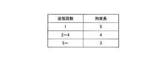
- FIG. 14 is a schematic diagram illustrating an example of a constraint length table according to Modification 11.
- FIG. 14 is a schematic block diagram which shows the structure of the decoding part which concerns on a prior art.
- FIG. 1 is a conceptual diagram of a communication system in each embodiment.
- mobile station devices User Equipment; user equipment
- eNodeB base station apparatus
- Base station apparatus eNodeB; base station apparatus
- a mobile station apparatus 1A includes a plurality of antennas and performs data transmission such as MIMO (Multiple Input Multiple Output) transmission and transmission diversity.
- the mobile station devices 2A and 3A are provided with one antenna and perform data transmission.
- the number of antennas of the mobile station apparatuses 1A to 3A and the base station apparatus 1B may be any number.
- the mobile station apparatuses 2A and 3A may include a plurality of antennas and perform data transmission by single user MIMO, or a plurality of mobile stations perform data transmission using the same time and the same frequency.
- User MIMO may be performed, or base station apparatus 1B may receive a multi-user signal with one antenna and remove interference using turbo equalization.
- the mobile station devices 2A and 3A in FIG. 1 are referred to as a mobile station device 1a
- the base station device 1B is referred to as a base station device 1b.
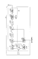
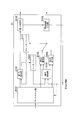
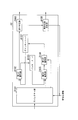
- FIG. 2 is a schematic block diagram showing the configuration of the mobile station device 1a according to the first embodiment of the present invention.
- the mobile station apparatus 1a includes a control signal receiving unit 11a, a transmission apparatus a1, and a transmission antenna 12a.
- the transmission device a1 includes a retransmission control unit a101, a buffer unit a102, a turbo coding unit C1, a modulation unit a103, an FFT (Fast Fourier Transform) unit a104, a mapping unit a105, an IFFT (Inverse Fast Fourier Transform), and an inverse fast Fourier transform.
- the control signal receiving unit 11a is notified of control information from the base station apparatus 1b.
- the control information includes band allocation information used for data transmission, modulation scheme information, and coding information (coding rate (or puncture pattern) and constraint length). However, the control information may include a part of these pieces of information, or may include other information.
- the control signal receiving unit 11a receives a delivery confirmation signal indicating whether or not the data is correctly received by the receiving device of the base station device 1b.
- the delivery confirmation signal includes an ACK (ACKnowledgement) signal or NACK (Negative ACKnowledgement).
- the ACK is a signal notified from the base station device 1b to the mobile station device 1a when the receiving device can correctly receive data.
- NACK is a signal notified from the base station apparatus 1b to the mobile station apparatus 1a when the receiving apparatus cannot receive data correctly, and indicates a retransmission request indicating that the base station apparatus 1b is requested to retransmit data.
- This delivery confirmation signal includes control information (referred to as retransmission control information) for the retransmission signal.
- the control signal receiving unit 11a extracts modulation scheme information and band allocation information from the received control information and retransmission control information, and outputs them to the modulation unit a103 and the mapping unit a105, respectively. In addition, the control signal receiving unit 11a outputs the encoded information extracted from the control information and the retransmission control information, and the delivery confirmation signal to the retransmission control unit 110.
- the retransmission control unit a101 determines whether the delivery confirmation signal input from the control signal receiving unit 11a is ACK or NACK. When it is determined as ACK, the retransmission control unit a101 outputs an initial transmission data input command to the buffer unit a102. In this case, the retransmission control unit a101 outputs the encoded information input from the control signal receiving unit 11a to the turbo encoding unit C1. On the other hand, when it is determined as NACK, the retransmission control unit a101 outputs a retransmission data input command to the buffer unit a102. In this case, the retransmission control unit a101 outputs the encoded information of the retransmission control information input from the control signal receiving unit 11a to the turbo coding unit C1.
- the buffer unit a102 stores the input data bits.
- the buffer unit a102 outputs the next data bit sequence (referred to as initial transmission data bit sequence) of the transmitted data bit sequence in the previous frame to the turbo encoding unit C1.
- initial transmission data bit sequence the next data bit sequence of the transmitted data bit sequence in the previous frame
- turbo encoding unit C1 the buffer unit a102 outputs the same data bit sequence (referred to as a retransmission data bit sequence) as the transmitted data bit sequence in the previous frame to the turbo encoding unit C1.
- the turbo encoding unit C1 generates encoded bits by turbo-encoding the bit string input from the buffer unit a102 based on the encoding information input from the retransmission control unit a101. Bits for cyclic redundancy check (CRC) are added to the encoded bits.
- the turbo encoder C1 outputs the generated encoded bits to the modulator a103. Details of the turbo encoding unit C1 will be described later.
- the modulation unit a103 generates a modulation symbol by modulating the coded bits input from the turbo coding unit C1 with the modulation method indicated by the modulation method information input from the control signal receiving unit 11a.
- the modulation scheme includes, for example, QPSK (Quaternary Phase Shift Keying) and 16QAM (16-ary Quadrature Amplitude Modulation).
- the modulation unit a103 outputs the generated modulation symbol to the FFT unit a104.
- the FFT unit a104 converts the modulation symbol input from the modulation unit a103 from a time domain signal to a frequency domain signal, and outputs the signal to the mapping unit a105.
- the mapping unit a105 arranges (maps) the signal input from the FFT unit a104 in each band based on the band allocation information input from the control signal receiving unit 11a and outputs the signal to the IFFT unit a106.
- the IFFT unit a106 converts the signal input from the mapping unit a105 from a frequency domain to a time domain signal, and outputs the signal to the reference signal multiplexing unit a107.
- the reference signal multiplexing unit a107 generates a reference signal in which waveforms are stored in advance in the transmitting device a1 of the mobile station device 1a and the receiving device b1 of the base station device 1b, and the signal input from the IFFT unit a106 in the time domain. Multiplex. For example, the transmission device a1 may multiplex the reference signal in the frequency domain with the signal before the IFFT unit a106 processes.
- the reference signal multiplexing unit a107 outputs the multiplexed signal to the transmission processing unit a108.
- the transmission processing unit a108 inserts a CP (Cyclic Prefix) into the signal input from the reference signal multiplexing unit a107.
- the transmission processing unit a108 performs D / A (Digital / Analog; digital / analog) conversion on the signal after inserting the CP, and upconverts the signal to a radio frequency.
- the transmission processing unit a108 amplifies the signal after up-conversion to transmission power using PA (Power Amplifier), and transmits it through the transmission antenna 12a.
- PA Power Amplifier
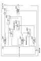
- FIG. 3 is a schematic block diagram showing the configuration of the turbo encoding unit C1 according to the present embodiment.
- the turbo coding unit C1 includes a CRC adding unit C111, an interleaver C112, a coding scheme selecting unit C113, a first coding unit C114, a second coding unit C115, a third coding unit C116, a puncturing unit C117, And a sign bit output unit C118.
- the first encoding unit C114 and the second encoding unit C115 perform encoding with a constraint length of “4”.
- the third encoding unit C116 performs encoding with a constraint length of “3”.
- the constraint length of the third encoding unit C116 is not limited to this constraint length value as long as the constraint length is different from that of the other encoding units.
- the turbo encoding unit C1 may include an encoding unit having a constraint length different from that of other encoding units.
- the CRC adding unit C111 receives a bit string (initial transmission data bit string or retransmission data bit string) from the buffer unit a102.
- the CRC adding unit C111 adds a cyclic redundancy check bit to the input bit string, and outputs the bit sequence to the interleaver C112 and the first encoding unit C114.
- the interleaver C112 rearranges (interleaves) the bit string input from the CRC adding unit C111 in a predetermined order and outputs the bit sequence to the encoding scheme selecting unit C113.
- the encoding scheme selection unit C113 outputs the bit string input from the interleaver C112 to the encoding unit corresponding to the constraint length indicated by the encoding information input from the retransmission control unit a101. Specifically, the coding scheme selection unit C113 outputs a bit string to the third coding unit C116 when the constraint length indicated by the encoding information is “3”, while the constraint length indicated by the encoding information. Is “4”, a bit string is output to the second encoding unit C115.
- the first encoding unit C114 outputs the systematic bits that are the input bit string to the code bit output unit C118. Also, the first encoding unit C114 encodes the bits input from the CRC adding unit C111 using an RSC (recursive systematic convolution) code having a constraint length of “4”. The first encoding unit C114 outputs the parity bits generated by encoding to the puncturing unit C117. The second encoding unit C115 encodes the bits input from the encoding method selection unit C113 using an RSC code having a constraint length of “4”. The second encoding unit C115 outputs the parity bits generated by encoding to the puncturing unit C117.
- RSC recursive systematic convolution
- the third encoding unit C116 encodes the bits input from the encoding method selection unit C113 using an RSC code having a constraint length of “3”.
- the third encoding unit C116 outputs the parity bits generated by encoding to the puncture unit C117.
- the puncture unit C117 stores in advance puncture information in which a coding rate and a puncture pattern are associated with each other.
- the puncture unit C117 selects a puncture pattern from the puncture information based on the coding rate indicated by the coding information input from the retransmission control unit a101.
- the puncturing unit C117 punctures the parity bits input from the first encoding unit C114 and the second encoding unit C115 or the third encoding unit C116 with the selected puncture pattern.
- the puncturing unit C117 outputs the punctured parity bits to the code bit output unit C118.
- the code bit output unit C118 generates encoded bits by concatenating the systematic bits input from the first encoding unit C114 and the parity bits input from the puncture unit C117 according to a predetermined concatenation order. To do. Specifically, the code bit output unit C118 includes systematic bits (referred to as a bit string B11), a parity bit part (referred to as a bit string B12) of the first encoding unit C114, the second encoding unit C115, or the third encoding. Concatenation is performed in the order of the parity bit part (bit string B13) of the part C116. The sign bit output unit C118 outputs the generated coded bits.
- the constraint length indicated by the encoded information is “4”.
- the constraint length indicated by the encoded information is “3”.
- the configuration of the turbo coding unit C1 the initial transmission data bit string output via the CRC adding unit C111, the interleaver C112, and the coding method selection unit C113 is encoded by the second coding unit C115 ( The constraint length is “4”) and punctured by the puncture unit C117.
- the retransmission data bit string output via the CRC adding unit C111, the interleaver C112, and the encoding scheme selecting unit C113 is encoded (constraint length “3”) by the third encoding unit C116, and the puncturing unit C117. Punctured. That is, the turbo encoding unit C1 has a constraint length “3” (encoding unit C116) and a constraint length “4” (encoding unit) different from the constraint length “4” (encoding units C114 and C115) used in the initial transmission. 117) is used together, and bits are encoded to generate a retransmission signal.
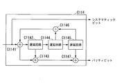
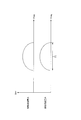
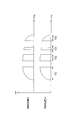
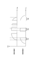
- FIG. 4 is a schematic diagram illustrating a configuration of the first encoding unit C114 according to the present embodiment.
- the first encoding unit C114 includes adders C1141, C1143, C1146, C1147, and delay circuits C1142, C1144, C1145.
- Adders C1141, C1143, C1146, and C1147 add the input bits.
- the delay circuits C1142, C1144, and C1145 delay the input bit by 1 bit and output it.
- the configuration of the second encoding unit C115 is obtained by removing the output of systematic bits from the configuration of the first encoding unit C114.
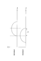
- the third encoding unit C116 includes adders C1161, C1163, C1165, and delay circuits C1162, C1164. Adders C1161, C1163, and C1165 add the input bits.
- the delay circuits C1162 and C1164 delay the input bits by one bit and output them.
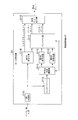
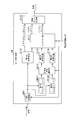
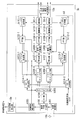
- FIG. 6 is a schematic block diagram illustrating the configuration of the base station device 1b according to the present embodiment.
- the base station apparatus 1b includes a reception antenna 11b, a reception apparatus b1, a control information generation unit 12b, and a delivery confirmation signal transmission unit 13b.
- the reception device b1 includes a reception processing unit b101, a reference signal separation unit b102, a propagation path estimation unit b103, an FFT unit b104, a demapping unit b105, a soft canceller unit b106, an equalization unit b107, a signal addition unit b108, an IFFT unit b109, A demodulator b110, a decoder D1, a symbol generator b111, an FFT unit b112, and a replica generator b113 are included.
- the reception processing unit b101 receives a signal transmitted from the mobile station device 1a via the reception antenna 11b.
- the reception processing unit b101 down-converts the received signal to a baseband frequency and performs A / D (Analog / Digital) conversion.
- the reception processing unit b101 removes the CP from the signal after A / D conversion, and outputs the signal to the reference signal separation unit b102.
- the reference signal separation unit b102 divides the signal input from the reception processing unit b101 into a reference signal and a signal other than the reference signal.
- the reference signal separation unit b102 outputs the divided reference signal to the propagation path estimation unit b103, and outputs a signal other than the reference signal to the FFT unit b104.
- the propagation path estimation unit b103 estimates the frequency response of the propagation path (referred to as propagation path characteristics) based on the reference signal input from the reference signal separation unit b102 and the reference signal stored in advance.
- the propagation path estimation unit b103 outputs the propagation path characteristic information indicating the estimated propagation path characteristics to the control information generation unit 12b, the equalization unit b107, and the replica generation unit b113.
- the control information generation section 12b Based on the propagation path characteristics indicated by the information input from the propagation path estimation section b103, the control information generation section 12b assigns a band to each mobile station apparatus 1a, a modulation scheme, a coding rate (or puncture pattern), and a constraint. Determine the length.
- the control information generating unit 12b generates band allocation information indicating the determined band allocation, modulation scheme information indicating the modulation scheme, encoding information indicating the coding rate (or puncture pattern), and constraint length.
- the control information generation unit 12b notifies the mobile station apparatus 1a of the control information including the generated band allocation information, modulation scheme information, and encoding information.
- the control information generation unit 12b outputs the generated band allocation information to the demapping unit b105.
- the control information generation unit 12b outputs the generated modulation scheme information to the demodulation unit b110 and the symbol generation unit b111.
- the control information generation unit 12b outputs the generated encoded information to the decoding unit D1.
- the FFT unit b104 converts the signal input from the reference signal separation unit b102 from a time domain signal to a frequency domain signal, and outputs the signal to the demapping unit b105.
- the demapping unit b105 extracts (demappings) the signal input from the FFT unit b104 from each band based on the band allocation information input from the control information generation unit 12b, and outputs the extracted signal to the soft canceller unit b106.
- the demapping unit b105 performs demapping based on the band allocation information.
- the soft canceller unit b106 receives (feeds back) a replica signal (soft replica) of a desired signal generated from the decoded data bits from the replica generation unit b113.
- the soft canceller unit b106 stores the signal input from the demapping unit b105, and subtracts the input soft replica from the stored signal.
- the soft canceller unit b106 outputs the subtracted signal to the equalization unit b107.
- the signal input from the demapping unit b105 is output to the equalizing unit b107 as it is.
- the equalization unit b107 performs equalization processing on the signal input from the soft canceller unit b106 based on the channel characteristic information input from the channel estimation unit b103. This equalization processing is processing for compensating for distortion due to a radio propagation path by multiplying a weight based on a MMSE (Minimum Mean Square Error) standard, a ZF (Zero Forcing) weight, or the like.
- the equalization unit b107 outputs the equalized signal to the signal addition unit b108.
- the signal adder b108 receives a symbol frequency domain replica signal generated from the decoded data bits from the FFT unit b112.
- the signal addition unit b108 adds the input replica signal to the signal input from the equalization unit b107.
- the signal adder b108 outputs the added signal to the IFFT unit b109.
- the IFFT unit b109 converts the signal input from the signal addition unit b108 from a frequency domain to a time domain signal and outputs the signal to the demodulation unit b110. Based on the modulation scheme information input from the control information generation unit 12b, the demodulation unit b110 demodulates the signal input from the IFFT unit b109 to convert it into encoded bits. However, when the decoding unit D1 determines the modulation scheme information for the retransmission signal, the demodulation unit b110 demodulates based on the modulation scheme information. The demodulator b110 outputs the demodulated encoded bits to the decoder D1.
- the decoding unit D1 decodes the encoded bits input from the demodulation unit b110 based on the encoded information input from the control information generation unit 12b. However, when the decoding unit D1 determines the encoding information for the retransmission signal, the decoding unit D1 decodes the encoded bit of the retransmission signal based on the determined encoding information. The decoding unit D1 checks whether or not the data bits have been correctly acquired based on the cyclic redundancy check bits included in the decoded bit string. The decoding unit D1 determines retransmission control information based on the inspection result after performing feedback to the soft canceller an arbitrary number of times.
- the decoding unit D1 outputs the data bits excluding the cyclic redundancy check bits and the retransmission control information to the external device.
- the error correction decoding result of the encoded bit by the decoding unit D1 is an error
- a bit punctured again with respect to the decoded bit is output to the symbol generation unit b111.
- the decoding unit D1 outputs a transmission command and retransmission control information for transmitting a delivery confirmation signal to the delivery confirmation signal transmission unit 13b based on the test result after feedback to the soft canceller any number of times or a predetermined number of times. Details of the decoding unit D1 will be described later.
- the symbol generation unit b111 generates a symbol replica by performing the same processing (modulation) as the modulation unit a103 of the mobile station apparatus 1a based on the modulation scheme information input from the control information generation unit 12b. However, when the decoding unit D1 determines the modulation scheme information for the retransmission signal, the symbol generation unit b111 modulates based on the modulation scheme information.
- the symbol generation unit b111 outputs the generated symbol replica to the FFT unit b112.
- the FFT unit b112 converts the symbol replica input from the symbol generation unit b111 from a time domain to a frequency domain signal (replica signal), and outputs the signal to the replica generation unit b113 and the signal addition unit b108.
- the replica generation unit b113 generates a soft replica by multiplying the propagation path characteristic information input from the propagation path estimation unit b103 by the replica signal input from the FFT unit b112.
- the replica generation unit b113 outputs the generated soft replica to the soft canceller unit b106.
- the delivery confirmation signal transmission unit 13b notifies the mobile station apparatus 1a of ACK or NACK as a delivery confirmation signal in accordance with the transmission command input from the decoding unit D1.
- the delivery confirmation signal transmitting unit 13b notifies the delivery confirmation signal including the retransmission control information input from the decoding unit D1.
- the delivery confirmation signal transmission part 13b may notify NACK and retransmission control information simultaneously, and may notify separately at a different timing.
- the inter-symbol interference is obtained by using the soft canceller and the equalizer in the single carrier as the MAP detector and performing the reception process for the repetition process of the MAP detector and the decoder.
- turbo equalization configuration is not limited to this example.
- the present invention can be applied to a case where an intersymbol interference or intercarrier interference is canceled by a turbo equalization reception process in which a MAP detector in a multicarrier is a soft canceller and the MAP detector and decoder are repeated.
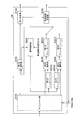
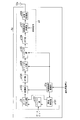
- FIG. 7 is a schematic block diagram showing the configuration of the decoding unit D1 according to this embodiment.
- the decoding unit D1 includes a depuncture unit D101, a first decoding unit D102, an interleaver D103, a decoding control unit D104, a second decoding unit D105, a third decoding unit D106, a deinterleaver D107, an error determination. Part D108 and retransmission control determining part D109.
- the depuncture unit D101 and the decoding control unit D104 receive the encoded information from the control information generation unit 12b and the retransmission control determination unit D109.
- the depuncture unit D101 and the decoding control unit D104 select the encoding information from the retransmission control determination unit D109 when performing processing on the retransmission signal, and the encoding information from the control information generation unit 12b otherwise. Select to process.
- the depuncture unit D101 divides the encoded bits input from the demodulation unit b110 according to the same concatenation order used by the code bit output unit C118 of the turbo encoding unit C1. Specifically, the depuncture unit D101 divides into the above bit strings B11, B12, and B13. The depuncture unit D101 stores the same puncture pattern information as that stored by the puncture unit C117. The depuncture unit D101 selects a puncture pattern from the puncture information based on the selected encoding information. The depuncture unit D101 inserts (depunctures) a bit indicating “0” into a portion punctured with the selected puncture pattern for the divided bit strings B12 and B13.
- the depuncture unit D101 outputs the divided bit string B11 (referred to as systematic bit 11) and the depunctured bit string B12 (referred to as parity bit 21) to the first decoding unit D102. Further, the depuncture unit D101 outputs the depunctured bit string B13 (referred to as the parity bit 22) to a decoding unit corresponding to the constraint length indicated by the selected encoded information. Specifically, when the constraint length indicated by the encoding information is “3”, the depuncture unit D101 outputs the parity bit 22 to the third decoding unit D106, while the constraint length indicated by the encoding information is “ In the case of “4”, the parity bit 22 is output to the second decoding unit D105.
- the first decoding unit D102 stores the parity bit 1 input from the depuncture unit D101.
- the first decoding unit D102 performs decoding processing based on MAP (Maximum A Positive Probability) estimation using the stored parity bit 21 and the bit string (systematic bit 12) input from the deinterleaver D107. Accordingly, the first decoding unit D102 performs error correction processing on desired data bits (referred to as systematic bits 13). However, in the first process, the first decoding unit D102 performs a decoding process by MAP estimation using the stored parity bit 21 and systematic bit 11.
- the first decoding unit D102 outputs the decoded systematic bit 13 to the error determination unit D108 when the predetermined number of decoding processes are performed, and performs the decoding when the predetermined number of decoding processes are not performed.
- the systematic bit 13 is output to the interleaver D103.
- the interleaver D103 rearranges (interleaves) the systematic bits 13 input from the first decoding unit D102 in a predetermined order and outputs the rearranged bit string to the decoding control unit D104. Called systematic bit 14).
- the predetermined order is the same as the order used by the interleaver C112 of the turbo encoding unit C1.
- the decoding control unit D104 outputs the systematic bit 14 input from the interleaver D103 to a decoding unit corresponding to the constraint length indicated by the selected encoding information.
- the decoding control unit D104 outputs the systematic bit 14 to the third decoding unit D106, while the constraint length indicated by the encoding information is In the case of “4”, the systematic bit 14 is output to the second decoding unit D105.
- the second decoding unit D105 stores the parity bit 22 input from the depuncture unit D101.
- the second decoding unit D105 performs a decoding process based on MAP estimation using the stored parity bit 22 and the systematic bit 14 input from the interleaver D103. Accordingly, the second decoding unit D105 performs error correction processing on the desired interleaved data bit (referred to as systematic bit 15).
- the second decoding unit D105 performs a decoding process of the constraint length “4”.
- the second decoding unit D105 outputs the decoded systematic bit 15 to the deinterleaver D107.
- the third decoding unit D106 stores the parity bit 22 input from the depuncture unit D101.
- the third decoding unit D106 uses the stored parity bit 22 and the systematic bit 14 input from the interleaver D103 to perform decoding processing based on MAP estimation, thereby interleaving desired data bits (systematic bits). 16) is subjected to error correction processing.
- the third decoding unit D106 performs a decoding process of the constraint length “3”.
- the third decoding unit D106 outputs the decoded systematic bit 16 to the deinterleaver D107.
- FIG. 7 the case where the deinterleaver D107 is connected to the second decoding unit D105 is described. However, the deinterleaver D107 is either the second decoding unit D105 or the third decoding unit D106. The connection can be switched to. Specifically, the deinterleaver D107 is connected to a decoding unit corresponding to the constraint length indicated by the encoding information.
- the deinterleaver D107 rearranges the systematic bits 15 input from the second decoding unit D105 or the systematic bits 16 input from the third decoding unit D106 in a predetermined order, so that the first decoding unit Output to D102 (the bit string after the rearrangement is systematic bit 12).
- the predetermined order is an order reverse to the order used by the interleaver C112.
- the systematic bit 12 input from the deinterleaver D107 is decoded by the first decoding unit D102, interleaved by the interleaver D103, and decoded by the second decoding unit D105 or the third decoding unit D106. Is done.
- the decoded bit string is then interleaved by the deinterleaver D107 and input to the first decoding unit D102.
- the systematic bit 12 repeats these processes a predetermined number of times, and outputs it to the error determination unit D108.
- the decoding unit D1 can perform decoding by switching between the decoding unit and the deinterleaver even when an encoded retransmission signal is received with a constraint length different from the constraint length of the encoded bits received in the initial transmission. it can.
- the error determination unit D108 extracts a cyclic redundancy check bit from the systematic bit 13 input from the first decoding unit D102, and checks whether or not the data bit has been correctly acquired based on this bit. If it is determined that the data has been correctly acquired (no error), the error determination unit D108 outputs the acquired data bits to an external device. In this case, the error determination unit D108 outputs a transmission command indicating transmission of ACK to the delivery confirmation signal transmission unit 13b. On the other hand, when it is determined that the data cannot be acquired correctly (there is an error), the error determination unit D108 outputs the acquired data bits to the symbol generation unit b111.
- the error determination unit D108 counts the number of times it is determined that acquisition is not possible, that is, the number of times equalization processing has been performed (referred to as the number of equalizations). If the error determination unit D108 determines that the data cannot be correctly acquired when the number of equalizations exceeds a predetermined value, the error determination unit D108 outputs information indicating that retransmission is requested to the retransmission control determination unit D109.
- the retransmission control determination unit D109 determines that the constraint length is “3” when information indicating that retransmission is requested is input. This restraint length is shorter than the initially sent restraint length “4”. In this case, in the communication system, in retransmission, encoding and decoding are performed with a constraint length shorter than the constraint length of the initial transmission (previous transmission) that could not be received correctly.
- the retransmission control determination unit D109 generates retransmission control information including encoded information indicating the determined constraint length.
- the retransmission control determination unit D109 outputs the generated retransmission control information and a transmission command indicating transmission of NACK to the delivery confirmation signal transmission unit 13b.
- retransmission control determining section D110 outputs the encoded information included in the generated retransmission control information to depuncture section D101 and decoding control section D104.
- retransmission control determining section D109 may determine coding information indicating band allocation information, modulation scheme information, and coding rate (or puncture pattern) based on propagation path characteristic information. Then, retransmission control information including these pieces of information is generated.
- the error determination unit D108 has been described as an example in which the bit output from the first decoding unit D102 after the turbo decoding is repeated an arbitrary number of times or a predetermined number of times, the turbo decoding is performed an arbitrary number of times or a predetermined number of times. May be output from the second decoding unit D105 or the third decoding unit D106 after the number of repetitions.
- FIG. 31 is a schematic block diagram showing the configuration of the decoding unit E1 according to the conventional technique.
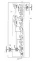
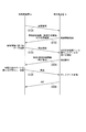
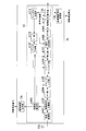
- FIG. 8 is a sequence diagram showing an example of the operation of the communication system according to the present embodiment.
- this figure is an example of the uplink communication from the mobile station apparatus 1a to the base station apparatus 1b.
- This figure is an example in which an error is detected in the first transmission and no error is detected in the second transmission (first retransmission).
- Step S101 The mobile station apparatus 1a transmits a reference signal to the base station apparatus 1b.
- This reference signal may be multiplexed with a data signal, or may be a signal in which only the reference signal is transmitted without multiplexing. Thereafter, the process proceeds to step S102.
- Step S102 The base station apparatus 1b receives the reference signal transmitted in step S101, and estimates the propagation path characteristic from the received reference signal.
- the base station apparatus 1b determines control information (including band allocation information, modulation scheme information, and coding information) for the mobile station apparatus 1a based on the estimated propagation path characteristics.
- the base station device 1b transmits the determined control information to the mobile station device. Thereafter, the process proceeds to step S103.
- Step S103 The mobile station apparatus 1a receives the control information transmitted in step S103, and transmits a signal obtained by encoding and modulating data bits based on the received control information (initial transmission; initial transmission). Thereafter, the process proceeds to step S104.
- Step S104 The base station apparatus 1b receives the signal transmitted in step S103, and demodulates and decodes the received signal based on the control information notified in S102. The base station apparatus 1b performs a cyclic redundancy check on the decoded data bit to check whether the data bit has been correctly acquired. In the example of FIG. 8, it is determined that the data bits cannot be acquired correctly, that is, an error is detected.
- the base station apparatus 1b transmits a NACK signal and retransmission control information (including band allocation information, modulation scheme information, and encoding information) as a delivery confirmation signal. Thereafter, the process proceeds to step S105. If it is determined that the data bits have been correctly acquired, the base station apparatus 1b transmits an ACK and completes the transmission of the data bits.
- retransmission control information including band allocation information, modulation scheme information, and encoding information
- Step S105 The mobile station apparatus 1a receives the delivery confirmation signal transmitted in step S104. Based on the received delivery confirmation signal, the mobile station device 1a encodes and modulates the same data bits as the data bits transmitted in step S103, and generates a retransmission signal. Here, the constraint length used for retransmission encoding is different from the constraint length used for encoding in step S103.
- the mobile station apparatus 1a transmits the generated retransmission signal, that is, retransmits the data bit signal. Thereafter, the process proceeds to step S106.
- the base station apparatus 1b receives the signal transmitted in step S105, and demodulates and decodes it using the received retransmission signal and initial transmission signal.
- the base station apparatus 1b performs a cyclic redundancy check on the decoded data bit to check whether the data bit has been correctly acquired. In the example of FIG. 8, it is determined that the data bits have been correctly acquired. In this case, the base station apparatus 1b transmits an ACK signal as a delivery confirmation signal.
- the mobile station apparatus 1a generates a retransmission signal by encoding bits with a constraint length different from the constraint length used in the previous (initial transmission) transmission, and the generated retransmission.
- the receiving device b1 repeats equalization using bits of the retransmission signal, which are bits decoded with a constraint length different from the constraint length used in the previous (initial transmission) reception.
- the communication system can improve communication quality. For example, by using a constraint length shorter than the constraint length used in the previous communication, turbo equalization can be converged and communication quality can be improved in the communication system.
- the turbo equalization when the turbo equalization is retransmitted without converging, the turbo equalization can be converged and the communication quality can be improved. Therefore, in the communication system, it is possible to improve the error rate characteristic at the time of retransmission, and to prevent a decrease in cell throughput.
- ⁇ Modification 1> In the first embodiment, the case has been described in which encoded information indicating the constraint length is transmitted from the base station apparatus 1b to the mobile station apparatus 1a. In the first modification, a case will be described in the communication system where the constraint length is selected according to whether the delivery confirmation signal is ACK or NACK. In this modification, the encoding scheme selection unit C113 and the retransmission control determination unit D109 store a constraint length table (FIG. 9) in advance.
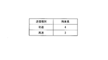
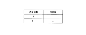
- FIG. 9 is a schematic diagram illustrating an example of a constraint length table according to the first modification.
- the constraint length table has a column for each item of the transmission type indicating whether the transmission is initial transmission or retransmission, and the constraint length.
- the constraint length table is two-dimensional tabular data composed of rows and columns in which information indicating the constraint length is stored for each transmission type. In this figure, for example, when the transmission type is “initial transmission”, the constraint length “4” is associated, and when the transmission type is “retransmission”, the constraint length “3” is associated.
- the encoding scheme selection unit C113 determines whether the transmission type is initial transmission or retransmission by determining whether the delivery confirmation signal is ACK or NACK. In the case of ACK (initial transmission), the encoding scheme selection unit C113 outputs a bit string to the second encoding unit C115 whose constraint length is “4”. On the other hand, in the case of NACK (retransmission), the encoding scheme selection unit C113 outputs a bit string to the third encoding unit C116 whose constraint length is “3”. As described above, according to the first modification, the constraint length can be changed without transmitting encoded information indicating the constraint length from the base station device 1b to the mobile station device 1a, thereby improving transmission efficiency. be able to.
- ⁇ Modification 2> In the first embodiment, the case has been described in which the constraint length is determined according to retransmission or initial transmission. In the second modification, the case where the constraint length is selected according to the number of transmissions in the communication system will be described.
- the encoding scheme selection unit C113 and the retransmission control determination unit D109 according to the second modification store a constraint length table (FIG. 10) in advance.
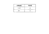
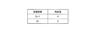
- FIG. 10 is a schematic diagram illustrating an example of a constraint length table according to the second modification.
- the constraint length table has columns for each item of the number of transmissions and the constraint length.
- the constraint length table is two-dimensional tabular data composed of rows and columns in which information indicating the constraint length is stored for each transmission count. In this figure, for example, when the number of transmissions is “1” or more and “2” or less, the constraint length “4” is associated, and when the number of transmissions is “3” or more, the constraint length “3” is associated. It has been.
- the encoding method selection unit C113 and the retransmission control determination unit D109 count the number of transmissions.
- the encoding scheme selection unit C113 and the retransmission control determination unit D109 select a constraint length corresponding to the counted number of transmissions based on a constraint length table stored in advance. Only the retransmission control determining unit D109 may store the constraint length table and select the constraint length based on the constraint length table. In this case, retransmission control determining section D109 transmits encoded information indicating the selected constraint length to mobile station apparatus 1a.
- communications with different constraint lengths are not limited to initial transmission and retransmission.
- the encoding scheme selection unit C113 and the retransmission control determination unit D109 are different between the first retransmission (transmission count “2”) and the second retransmission (transmission count “3”).
- the coding length may be selected. That is, the transmission before the constraint lengths are different is not limited to the initial transmission, and may be retransmission.
- turbo coding (first coding unit C114 and second coding unit C115) with a constraint length of “4” is performed in the first transmission, and part of the retransmission is performed.
- turbo encoding (first encoding unit C114 and third encoding unit C116) with a constraint length “3” is performed
- the decoding method is not limited to the above.
- the code control unit D104 may switch the output destination according to the number of turbo decoding iterations. A modification is shown below. In FIG. 7, systematic bits that are output from the first decoding unit D102 are rearranged by the interleave D103, and the rearranged bits are input to the decoding control unit 104.
- the decoding control unit D104 inputs the systematic bits input from the interleaver D103 to the second decoding unit D105.
- the decoding result in the second decoding unit D105 is input to the first decoding unit D102 via the deinterleaver D107.
- the initial transmission is the same as the conventional turbo decoding by the first decoding unit D102 and the second decoding unit D105.
- the decoding control unit D104 inputs the systematic bits input from the interleaver D103 to the third decoding unit D106.
- the decoding result of the third decoding unit D106 is input to the first decoding unit D102 via the deinterleaver D107.
- the decoding result in the first decoding unit D102 is again output to the decoding control unit D104 via the interleaver D103, but the decoding control unit D104 changes the decoding unit to be output.
- the decoding control unit D104 outputs the input bits to the second decoding unit D105 instead of the third decoding unit D106 used in the first decoding process.
- the second decoding unit D105 decoding is performed using the parity bit transmitted in the initial transmission, and the result is output to the deinterleaver D107.
- the deinterleaver D107 performs rearrangement of processing reverse to that of the interleaver, and outputs the rearranged bits to the first decoding unit D102.
- the decoding process is performed by repeating this process. Therefore, in the decoding unit D1, the third decoding unit D106 is used in odd-numbered processes such as the first, third, and fifth iterations of turbo decoding, and even numbers such as the second, fourth, and sixth times are used.
- the second decoding unit D105 is used in the processing of the first time.
- the parity bits received in the initial transmission and the retransmission can be used as in the case where the constraint length is not changed between the initial transmission and the retransmission.
- the error rate characteristic can be improved and the cell throughput can be prevented from decreasing.
- the configuration of the decoding unit D1 is not limited to this, and may be the configuration of the decoding unit D2 as shown in FIG.
- FIG. 11 is a schematic diagram illustrating a configuration of the decoding unit D2 according to the fourth modification.
- the second decoding unit D105 and the third decoding unit D106 are connected in series.
- the systematic bit 14 output from the interleaver D103 is decoded by the second decoding unit D105 when the constraint length is “4”, and the third decoding unit when the constraint length is “3”.
- the data is decoded at D106 and output to the deinterleaver D107.
- the decoding unit D2 can perform communication with the constraint length changed without the code control unit D104, and the circuit and program can be simplified compared to the decoding unit D1.
- the first transmission signal is decoded by the first decoding unit D102, and the decoding result is used as prior information of the second decoding unit D105 or the third decoding unit D106.
- the decoding unit D1 may be configured to first decode the retransmission signal and use the decoding result as prior information of the first decoding unit D102.
- the communication system performs rearrangement of the bit order using rearrangement different from the rearrangement used in the previous transmission.
- a case will be described in which the communication system selects the constraint length depending on whether the delivery confirmation signal is ACK or NACK.
- the present invention is not limited to this, and in the communication system, as in the first embodiment, the base station device 1b determines the constraint length and transmits the encoded information indicating the determined constraint length to the mobile station device 1a. May be.
- the mobile station devices 2A and 3A in FIG. 1 are referred to as a mobile station device 2a
- the base station device 1B is referred to as a base station device 2b.
- FIG. 12 is a schematic block diagram showing the configuration of the mobile station device 2a according to the second embodiment of the present invention.
- the turbo coding unit C3 of the transmission apparatus a2 is different.
- other components control signal receiving unit 11a, transmission antenna 12a, retransmission control unit a101, buffer unit a102, modulation unit a103, FFT unit a104, mapping unit a105, IFFT unit a106, reference signal multiplexing unit a107, and transmission
- the function of the processing unit a108 is the same as that of the first embodiment. A description of the same functions as those in the first embodiment is omitted.
- FIG. 13 is a schematic block diagram showing the configuration of the turbo encoding unit C3 according to this embodiment.
- the turbo encoder C3 (FIG. 13) according to the present embodiment is compared with the turbo encoder C1 (FIG. 3) according to the first embodiment, the first interleaver C3121, the second interleaver C3122, and The encoding method selection unit C313 is different.
- the turbo coding unit C1 is a CRC adding unit C111, a first coding unit C114, a second coding unit C115, a third coding unit C116, a puncturing unit C117, and a code bit output.
- Part C118 has the same function as in the first embodiment. A description of the same functions as those in the first embodiment is omitted.
- the first interleaver C3121 rearranges (interleaves) the bit string input from the CRC adding unit C111 in a predetermined order.
- the first interleaver C3121 receives a delivery confirmation signal from the retransmission control unit a101.
- the first interleaver C3121 determines whether the input acknowledgment signal is ACK or NACK. That is, the first interleaver C 3121 determines whether the bit string to be processed is the first transmission or the retransmission.
- the first interleaver C3121 outputs the rearranged bit string to the encoding scheme selection unit C113.
- the first interleaver C3121 outputs the rearranged bit string to the second interleaver C3122.
- the second interleaver C3122 rearranges (interleaves) the bit string input from the first interleaver C3121 in a predetermined order and outputs the bit sequence to the encoding scheme selection unit C113.
- the second interleaver C3122 rearranges the bit strings so that they are in a different order from the bit strings output by the CRC adding unit C11 and the first interleaver C3121.
- the encoding scheme selection unit C313 receives the delivery confirmation signal from the retransmission control unit a101. The encoding scheme selection unit C313 determines whether the input delivery confirmation signal is ACK or NACK. If it is determined that the delivery confirmation signal is ACK, the encoding scheme selection unit C313 outputs the bit string input from the first interleaver C3121 to the second encoding unit C115. On the other hand, when it is determined that the delivery confirmation signal is NACK, the encoding scheme selection unit C313 outputs the bit string input from the second interleaver C3122 to the third encoding unit C116.
- the bit string output from the first interleaver C3121 is encoded by the second encoding unit C115.
- the bit string output from the first interleaver C3121 is interleaved by the second interleaver C3122 and encoded by the third encoding unit C116.
- FIG. 14 is a schematic block diagram showing the configuration of the base station device 2b according to this embodiment.
- the turbo decoding unit D3 of the receiving apparatus b2 is different.
- reception antenna 11b reception antenna 11b, control information generation unit 12b, delivery confirmation signal transmission unit 13b, reception processing unit b101, reference signal separation unit b102, propagation path estimation unit b103, FFT unit b104, demapping unit b105
- the functions of the soft canceller unit b106, equalization unit b107, IFFT unit b109, demodulation unit b110, symbol generation unit b111, FFT unit b112, and replica generation unit b113 are the same as those in the first embodiment. A description of the same functions as those in the first embodiment is omitted.
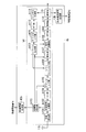
- FIG. 15 is a schematic block diagram showing the configuration of the decoding unit D3 according to this embodiment. Comparing the decoding unit D3 (FIG. 15) according to the present embodiment and the decoding unit D1 (FIG. 7) according to the first embodiment, the second decoding unit D305, the first interleaver D3031, the second interleaver The leaver D3032, the first deinterleaver D3071 and the second deinterleaver D3072 are different. However, the functions of other components (depuncture unit D101, first decoding unit D102, decoding control unit D104, third decoding unit D106, error determination unit D108, and retransmission control determination unit D109) are the same as those in the first embodiment. The form is the same. A description of the same functions as those in the first embodiment is omitted.
- the first interleaver D3031 rearranges the systematic bits 13 input from the first decoding unit D102 in a predetermined order (interleaved), and outputs the rearranged bits to the second decoding unit D305 (rearrangement).
- the subsequent bit string is referred to as systematic bit 14).
- the predetermined order is the same as the order used by the first interleaver C3121 of the turbo encoding unit C3.
- the second decoding unit D305 stores the parity bit 22 input from the depuncture unit D101.
- the second decoding unit D305 performs decoding processing based on MAP estimation using the stored parity bit 22 and the systematic bit 14 input from the first interleaver D3031.
- the second decoding unit D305 performs error correction on the desired interleaved data bit (referred to as systematic bit 15).
- the second decoding unit D305 receives the delivery confirmation signal from the retransmission control determination unit D109.
- the second decoding unit D305 determines whether the input delivery confirmation signal is ACK or NACK. When determining that the delivery confirmation signal is ACK, the second decoding unit D305 outputs the systematic bit 15 subjected to error correction to the first deinterleaver D3071.
- the second decoding unit D305 when it is determined that the delivery confirmation signal is NACK, the second decoding unit D305 outputs the systematic bit 15 subjected to error correction to the second interleaver D3032. In this case, the second decoding unit D305 switches the switch so as to be connected to the second interleaver D3032.
- the second interleaver D3032 rearranges the systematic bits 15 input from the second decoding unit D305 in a predetermined order (interleaved), and outputs the rearranged bits to the third decoding unit D106 (rearrangement).
- the subsequent bit string is called systematic bit 17).
- the predetermined order is the same as the order used by the second interleaver C3122 of the turbo encoding unit C3.
- the systematic bit 17 is decoded by the third decoding unit D106 and output to the second deinterleaver D3072.
- the second deinterleaver D3072 rearranges the bit sequence output from the third decoding unit D106 in a predetermined order and outputs the rearranged bit sequence to the first deinterleaver D3071 (the rearranged bit sequence is Systematic bit 18).
- the predetermined order is an order opposite to the order used by the second interleaver D3032.
- the first deinterleaver D3071 rearranges the systematic bit 15 input from the second decoding unit D305 or the systematic bit 18 input from the second deinterleaver D3072 in a predetermined order, and 1 to the decoding unit D102 (the rearranged bit string is the systematic bit 12).
- the predetermined order is an order opposite to the order used by the first interleaver D3031.
- the bit string output from the second decoding unit D305 is output to the first deinterleaver D3071.
- the bit string output from the second decoding unit D305 is interleaved by the second interleaver D3032 and decoded by the third decoding unit D106. Thereafter, the decoded bit string is deinterleaved by the second deinterleaver D3072 and output to the first deinterleaver D3071.
- the transmission device a2 reorders and encodes the bit sequence in an arrangement order different from the arrangement order used in the previous (initial transmission) transmission, and the reception device b2 ) Are rearranged and decoded in a different order from the order used for reception.
- the communication system can converge turbo equalization and improve communication quality. Therefore, in the communication system, it is possible to improve the error rate characteristic at the time of retransmission, and to prevent a decrease in cell throughput.
- communication in which the bit order is different is not limited to initial transmission and retransmission.
- the first interleaver C3121, the encoding scheme selection unit C113, and the second decoding unit D305 are different between the first retransmission (transmission count “2”) and the second retransmission (transmission count “3”).
- the output destination may be selected. That is, the transmission before the bit arrangement order is different is not limited to the initial transmission, and may be retransmission.
- the configurations of the turbo coding unit C3 and the decoding unit D3 are not limited to this, and the bit string input to the coding method selection unit C113 may be different depending on the type of acknowledgment signal (ACK or NACK). Good.
- the predetermined order used by the first interleaver C3121 and the second interleaver C3122 may be the same order or different orders.
- cord part C4 and the decoding part D4 as shown in FIG. 16, FIG. 17 may be sufficient.
- FIG. 16 is a schematic block diagram illustrating a configuration of a turbo encoding unit C4 according to the fifth modification.
- the turbo coding unit C4 (FIG. 16) according to the present modification is compared with the turbo coding unit C3 (FIG. 13) according to the second embodiment, the CRC adding unit C411 and the first interleaver C4121 are different.
- the functions of other components are the same as those in the first embodiment. A description of the same functions as those in the first embodiment is omitted.
- the CRC adding unit C411 receives a bit string (initial transmission data bit string or retransmission data bit string) from the buffer unit a102.
- the CRC adding unit C411 adds bits for cyclic redundancy check to the input bit string, and outputs the result to the first encoding unit C114.
- the CRC adding unit C411 receives the delivery confirmation signal from the retransmission control unit a101.
- the CRC adding unit C411 determines whether the input delivery confirmation signal is ACK or NACK. If it is determined that the delivery confirmation signal is ACK, the CRC adding unit C411 outputs the rearranged bit string to the first interleaver C4121.
- the CRC adding unit C411 when it is determined that the delivery confirmation signal is NACK, the CRC adding unit C411 outputs the rearranged bit string to the second interleaver C3122.
- the first interleaver C4121 rearranges (interleaves) the bit string input from the CRC adding unit C411 in a predetermined order and outputs the bit sequence to the encoding scheme selection unit C313.
- FIG. 17 is a schematic block diagram illustrating a configuration of the decoding unit D4 according to the fifth modification.
- the code control unit D404 and the second decoding unit D105 are different.
- the functions of other components are the same as in the second embodiment.
- a description of the same functions as those in the second embodiment is omitted.
- the function of the second decoding unit D105 is the same as that of the first embodiment, and a description thereof will be omitted.
- the code control unit D404 receives the delivery confirmation signal from the retransmission control determination unit D111.
- the code control unit D404 determines whether the input delivery confirmation signal is ACK or NACK. When it is determined that the delivery confirmation signal is ACK, the code control unit D404 outputs the systematic bit 13 input from the first decoding unit D102 to the first interleaver D3031. On the other hand, when it is determined that the delivery confirmation signal is NACK, the code control unit D404 outputs the systematic bit 13 input from the first decoding unit D102 to the second interleaver D3032. In FIG. 17, the case where the first decoding unit D102 is connected to the first deinterleaver D3071 is described.
- the first decoding unit D102 is configured to use the first deinterleaver D3071 or the second deinterleaver D3071.
- the connection can be switched to one of the deinterleavers D3072.
- the first decoding unit D102 is connected to the first deinterleaver D3071 or the second deinterleaver D3072 depending on whether the delivery confirmation signal is ACK or NACK, respectively. .
- the code control unit D404 may switch the output destination according to the number of times of turbo decoding repetition processing.
- the systematic bit that is the output from the first decoding unit D102 is input to the decoding control unit 104.
- the decoding control unit D404 inputs the input systematic bits to the first interleaver D3031.
- the systematic bits are rearranged by the first interleaver D3031, and the rearranged bits are input to the second decoding unit D105.
- the decoding result in the second decoding unit D105 is input to the first decoding unit D102 via the first deinterleaver D3071.
- the decoding control unit D404 inputs the input systematic bits to the second interleaver D3032.
- the systematic bits are rearranged by the second interleaver D3032, and the rearranged bits are input to the third decoding unit D106.
- the decoding result in the third decoding unit D106 is input to the first decoding unit D102 via the second deinterleaver D3072.
- the decoding result in the first decoding unit D102 is input again to the decoding control unit D404, but the decoding control unit D404 changes the output interleaver.
- the decoding control unit D404 outputs the input bits to the first interleaver D3031, not to the second interleaver D3032 used in the first decoding process.
- the bits rearranged by the first interleaver are decoded by the second decoding unit D105 using the parity bits transmitted in the initial transmission.
- the second decoding unit D105 outputs the result to the first deinterleaver D3071.
- the first deinterleaver D3071 performs rearrangement of processing opposite to that of the first interleaver D3031, and outputs the rearranged bits to the first decoding unit D102.
- the decoding process is performed by repeating this process.
- the second interleaver 3032, the third decoding unit D106, and the second deinterleaver D3072 are performed in odd-numbered processes such as the first, third, and fifth iterations of turbo decoding. Will be used.
- the first interleaver D3031, the second decoding unit D105, and the first deinterleaver D3071 are used in even-numbered processing such as the second time, the fourth time, and the sixth time.
- FIG. 18 is a schematic block diagram illustrating a configuration of the decoding unit D5 according to the sixth modification.
- the decoding unit D5 (FIG. 18) according to the present modification is compared with the decoding unit D3 (FIG. 15) according to the second embodiment, the second deinterleaver D5072 and the third decoding unit D506 are different.
- the functions of other components are the same as in the second embodiment. A description of the same functions as those in the second embodiment is omitted.
- the third decoding unit D506 stores the parity bit 22 input from the depuncture unit D101.
- the third decoding unit D506 uses the stored parity bit 22 and the systematic bit 17 input from the second interleaver D3032 to perform decoding processing by MAP estimation, thereby interleaving desired data bits. Error correction is performed on (systematic bit 16).
- the third decoding unit D506 performs a decoding process of the constraint length “3”.
- the third decoding unit D506 outputs the systematic bit 16 subjected to error correction to the second deinterleaver D5072.
- the second deinterleaver D5072 rearranges the systematic bits 16 output from the third decoding unit D506 in a predetermined order.
- the predetermined order is an order opposite to the order used by the second interleaver D3032.
- the second deinterleaver D5072 counts the number of processes, and determines whether or not a predetermined number of processes have been performed, whereby the second decoding unit D305, the second interleaver D3032, the third It is determined whether or not a series of decoding processes of the decoding unit D506 and the second deinterleaver D5072 have been performed a predetermined number of times.
- the second deinterleaver D5072 outputs the rearranged bit string to the first deinterleaver D3071 when the predetermined number of times of processing has been performed, and when the predetermined number of times of decoding processing has not been performed. Outputs the rearranged bit string to the second decoding unit D305. Due to the configuration of the decoding unit D5, in the case of retransmission, the bits input from the first interleaver D3031 to the second decoding unit D305 include the second decoding unit D305, the second interleaver D3032, A series of decoding processes of the third decoding unit D506 and the second deinterleaver D5072 are performed a predetermined number of times (this process is called decoding process A).
- the bits input from the depuncture unit D101 to the first decoding unit D102 are processed by the first decoding unit D102, the processing by the first interleaver, the decoding processing A, the first The process in the deinterleaver D3071 is performed a predetermined number of times and input to the error determination unit D108.
- FIG. 19 and FIG. 20 are diagrams when a continuous frequency band is allocated and the mobile station apparatuses 2A and 3A arrange signals in this frequency band.
- the signals of the mobile station apparatuses 2A and 3A are arranged so as to overlap the frequency band f1 and in FIG. 20 the frequency band f2.
- FIG. 22 are diagrams in the case where a distributed frequency band is allocated and the mobile station apparatuses 2A and 3A arrange signals in this frequency band.
- the signals of the mobile station apparatuses 2A and 3A are arranged so as to overlap the frequency bands f31 to f34 and in FIG. 22 the frequency bands f41 to f43.
- the frequency bands in which the mobile station apparatuses 2A and 3A arrange the signals may overlap all or may partially overlap.
- the base station apparatus B1 receives signals from the plurality of mobile station apparatuses 2A and 3A, removes the IUI from the received signals, and acquires data bits from the mobile station apparatuses 2A and 3A.
- the base station apparatus 1B is referred to as a base station apparatus 3b.
- the mobile station apparatuses 2A and 3A according to the present embodiment are the same as the mobile station apparatus 1a according to the first embodiment, description thereof is omitted.
- FIG. 23 is a schematic block diagram illustrating a configuration of the base station device 3b according to the present embodiment.
- the base station device 3b includes a reception antenna 11b, a transmission device b3, a control information generation unit 12b, and a delivery confirmation signal transmission unit 13b.
- the reception device b1 includes a reception processing unit b101, a reference signal separation unit b102, a propagation path estimation unit b303, an FFT unit b104, a demapping unit b305, soft canceller units b306-1, b306-2, and equalization units b107-1, b107.
- reception antenna 11b the control information generation unit 12b, the reception processing unit b101, the reference signal separation unit b102, the FFT unit b104, and the delivery confirmation signal transmission unit 13b are the same as those in the first embodiment. The description is omitted.
- the functions of the equalization units b107-1 and b107-2 are the same as those of the equalization unit b107, the functions of the IFFT units b109-1 and b109-2 are the same as those of the IFFT unit b109, and the demodulation unit b110- 1 and b110-2 have the same functions as the demodulation unit b110.
- the functions of the decoding units D1-1 and 1-2 are the same as those of the decoding unit D1, the functions of the symbol generation units b111-1 and b111-2 are the same as those of the symbol generation unit b111, and the FFT unit b112-1 , B112-2 has the same function as the FFT unit b112, and the functions of the ISI generation units b113-1 and b113-2 are the same as the replica generation unit b113. Description of these configurations is omitted.
- the propagation path estimation unit b303 receives the frequency response of the propagation path (propagation path) based on the reference signal from each of the mobile station devices 2A and 3A input from the reference signal separation unit b102 and the reference signal stored in advance. Estimated). The propagation path estimation unit b303 generates propagation path characteristic information indicating the estimated propagation path characteristics, the control information generation unit 12b, the equalization units b107-1, b107-2, the replica generation units b113-1, b113-2, and the IUI generation The data is output to the parts b314-1 and b314-2.
- the propagation path estimation unit b303 outputs the propagation path characteristic information about the mobile station apparatus 2A to the replica generation unit b113-1 and the IUI generation part b314-1, and the propagation path characteristic information about the mobile station apparatus 3A.
- the data is output to the replica generation unit b113-2 and the IUI generation unit b314-2.
- the demapping unit b305 extracts (demappings) the signal input from the FFT unit b104 from each band based on the band allocation information input from the control information generation unit 12b. However, when the decoding unit D1-1 or D1-2 determines band allocation information for the retransmission signal, the demapping unit b105 performs demapping based on the band allocation information.
- the demapping unit b305 outputs a signal from the mobile station device 2A to the soft canceller unit b106-1, and outputs a signal from the mobile station device 3A to the soft canceller unit b106-2.
- the soft canceller unit b306-1 receives the soft replica for the mobile station device 2A from the replica generation unit b113-1.
- the soft canceller unit b306-1 generates an IUI replica signal (referred to as IUI replica 1) generated for a signal from the mobile station apparatus 2A by a signal from a mobile station apparatus (mobile station apparatus 3A) other than the mobile station apparatus 2A. , Input from the IUI generation unit b 314-2.
- the soft canceller unit b306-2 receives the soft replica for the mobile station device 3A from the replica generation unit b113-2.
- the soft canceller unit b306-2 generates an IUI replica signal (referred to as IUI replica 2) generated for a signal from the mobile station apparatus 3A by a signal from a mobile station apparatus (mobile station apparatus 2A) other than the mobile station apparatus 3A. , Input from the IUI generation unit b 314-1.
- the soft canceller units b306-1 and b306-2 store the signal input from the demapping unit b305.
- the soft canceller units b306-1 and b306-2 subtract the input IUI replica and soft replica from the stored signal.
- the soft canceller units b306-1 and b306-2 output the subtracted signals to the equalization units b107-1 and b107-2, respectively.
- the IUI generation units b314-1 and b314-2 receive the channel characteristic information from the channel estimation unit b303. Further, the IUI generation units b314-1 and b314-2 are input with symbol replicas in the frequency domain from the FFT units b112-1 and b112-2, respectively. The IUI generation units b314-1 and b314-2 respectively generate IUI replicas 2 and 1 from the input symbol replicas based on the input propagation path characteristic information. The IUI generation units b314-1 and b314-2 output the generated IUI replicas 2 and 1 to the soft canceller units b306-1 and b306-2, respectively.
- communication quality can be improved even when signals overlap in a frequency band.
- turbo equalization is performed when turbo equalization is retransmitted without converging due to overlapping signals in the frequency band. Convergence and communication quality can be improved.
- ⁇ Modification 7> the case where the retransmission control determining unit D610 selects a constraint length according to the number of users with which signals overlap will be described.
- the retransmission control determination unit D109 according to the seventh modification stores a constraint length table (FIG. 24) in advance.
- FIG. 24 is a schematic diagram illustrating an example of a constraint length table according to Modification 7.
- the constraint length table has columns for each item of the number of users and the constraint length indicating the number of mobile station apparatuses 1a with which signals overlap.
- the constraint length table is two-dimensional tabular data composed of rows and columns in which information indicating the constraint length is stored for each user.
- a constraint length “4” is associated, and when the number of transmissions is “3” or more, a constraint length “3” is associated. It has been. That is, the greater the number of users, the shorter the constraint length.
- the retransmission control determination unit D610 selects the constraint length according to the bandwidth in which signals overlap, the number of antennas used by the base station apparatus, the modulation scheme used for transmission, and the coding rate. Also good. Examples of shortening the constraint length include a case where a bandwidth where signals overlap is wide, a case where the number of antennas used for reception is small, a case where the modulation multi-level number is high, and a case where the coding rate is high.
- the case where signals from a plurality of mobile station apparatuses 1a overlap has been described. However, the present invention is not limited to this, and is applied to a case where signals from different antennas overlap in a communication system. May be.
- FIG. 25 is an explanatory diagram illustrating clipping processing according to the fourth embodiment of the present invention.
- a signal spectrum S1 (frequency band f5) is a signal spectrum when clipping processing is not performed.
- the signal spectrum S11 (frequency band f51) is a signal spectrum when clipping processing is not performed. That is, the signal spectrum S12 (frequency band f52) is deleted by the clipping process.
- the mobile station devices 2A and 3A are referred to as a mobile station device 4a
- the base station device 1B is referred to as a base station device 4b.
- FIG. 26 is a schematic block diagram showing the configuration of the mobile station device 4a according to this embodiment.
- the control information receiving unit 41a and the clipping unit a409 of the transmitting apparatus a4 are different.
- transmission antenna 12a transmission antenna 12a, retransmission control unit a101, buffer unit a102, turbo coding unit C1, modulation unit a103, FFT unit a104, mapping unit a105, IFFT unit a106, reference signal multiplexing unit a107, and transmission processing
- the function of the part a108 is the same as that of the first embodiment. A description of the same functions as those in the first embodiment is omitted.
- the control information receiving unit 41a has the following functions in addition to the functions of the control signal receiving unit 11a of the first embodiment.
- the control signal receiving unit 11a receives control information and retransmission control information including clipping information indicating a frequency band to be clipped (frequency band f52 in the example of FIG. 25).
- the control information receiving unit 41a outputs the received clipping information and band allocation information to the clipping unit a409 and the mapping unit a105, respectively.
- the clipping unit a409 replaces the frequency signal indicated by the clipping information input from the control information receiving unit 41a with “0” (null) based on the band allocation information input from the control information receiving unit 41a. Is deleted (clipping processing).
- the clipping unit a409 outputs the replaced signal to the mapping unit a105.
- FIG. 27 is a schematic block diagram showing the configuration of the base station device 4b according to this embodiment.
- the control information generating unit 42b and the clipping unit b415 of the receiving apparatus b4 are different.
- other components reception antenna 11b, delivery confirmation signal transmission unit 13b, reception processing unit b101, reference signal separation unit b102, propagation path estimation unit b103, FFT unit b104, demapping unit b105, soft canceller unit b106, etc.
- the function of the conversion unit b107, the signal addition unit b108, the IFFT unit b109, the demodulation unit b110, the decoding unit D1, the symbol generation unit b111, the FFT unit b112, and the replica generation unit b113) is the same as that of the first embodiment. A description of the same functions as those in the first embodiment is omitted.
- the control information generation unit 42b has the following functions in addition to the functions of the control information generation unit 12b of the first embodiment.
- the control information generation unit 42b determines the frequency band to be clipped based on the propagation path characteristics indicated by the information input from the propagation path estimation unit b103.
- the control information generation unit 42b generates clipping information indicating the determined frequency band, and notifies the mobile station apparatus 1a of control information including the generated clipping information. Further, the control information generation unit 42b outputs the generated clipping information and band allocation information to the clipping unit b415.
- the clipping unit b415 sets the signal arranged in the frequency band indicated by the clipping information input from the control information generation unit 42b to “0” (null) based on the band allocation information input from the control information generation unit 42b. replace.
- the clipping unit a409 outputs the replaced signal to the replica generation unit a113.
- communication quality can be improved even when clipping is performed.
- the communication system can converge turbo equalization when the turbo equalization is retransmitted without converging due to clipping. It can be improved.
- the retransmission control determination unit D109 may select the constraint length according to the size of the band to be clipped. In this case, for example, the retransmission control determination unit D109 selects a shorter constraint length as the size of the band to be clipped increases. Further, retransmission control determining section D109 may select the constraint length according to the size of the band that is not clipped. In this case, for example, the retransmission control determination unit D109 selects a shorter constraint length as the size of the band to be clipped is smaller. In addition to the band to be clipped, the constraint length may be determined in consideration of any or all of the number of antennas used by the base station apparatus, the modulation scheme used for transmission, and the coding rate.
- ⁇ Modification 9> when the number of transmissions increases, the case where the constraint length is shorter or the same as the constraint length in the previous transmission has been described. However, the present invention is not limited to this. In the communication system, when the number of transmissions increases, the constraint length may be longer than the constraint length in the previous transmission.
- the encoding scheme selection unit C113 and the retransmission control determination unit D109 according to the ninth modification store a constraint length table (FIG. 28) in advance.
- FIG. 28 is a schematic diagram illustrating an example of a constraint length table according to the ninth modification.
- the constraint length table has columns for each item of the number of transmissions and the constraint length.
- the constraint length table is two-dimensional tabular data composed of rows and columns in which information indicating the constraint length is stored for each transmission count.
- n is a natural number. In this figure, for example, when the number of transmissions is “1”, the constraint length “3” is associated, and when the number of transmissions is “2” or more, the constraint length “4” is associated.
- the constraint length used for the retransmission signal is longer than the constraint length used in the previous transmission.
- ⁇ Modification 10> different constraint lengths may be used alternately in the communication system.
- the encoding scheme selection unit C113 and the retransmission control determination unit D109 according to the tenth modification store a constraint length table (FIG. 29) in advance.
- FIG. 29 is a schematic diagram illustrating an example of a constraint length table according to the tenth modification.
- the constraint length table has columns for each item of the number of transmissions and the constraint length.
- the constraint length table is two-dimensional tabular data composed of rows and columns in which information indicating the constraint length is stored for each transmission count.
- n is a natural number.
- the constraint length “4” is associated, and when the number of transmissions is an even number “2”, the constraint length “3” is associated. It has been.
- the constraint length “4” is associated.
- the constraint lengths having different lengths are alternately used.
- the present modification 10 can selectively apply the case where the constraint length is shortened to improve the convergence of turbo equalization and the case where the constraint length is lengthened to improve the reception characteristics.
- the communication quality can be improved based on the characteristics.
- the turbo encoding unit C1 includes three or more encoding units having different constraint lengths
- the decoding unit D1 includes three or more decoding units having different constraint lengths.
- the encoding scheme selection unit C113 and the retransmission control determination unit D109 according to the eleventh modification store a constraint length table (FIG. 30) in advance.
- FIG. 30 is a schematic diagram illustrating an example of a constraint length table according to the eleventh modification.
- the constraint length table has columns for each item of the number of transmissions and the constraint length.
- the constraint length table is two-dimensional tabular data composed of rows and columns in which information indicating the constraint length is stored for each transmission count.
- the constraint length “5” is associated, and when the number of transmissions is “2” or more and “4” or less, the constraint length “4” is associated.
- the constraint length “3” is associated.
- transmission apparatus a1, a2, and a4 have multiple transmission.
- An antenna may be provided.
- the case where the receiving devices b1 to b4 are provided with one transmission antenna has been described.
- the present invention is not limited to this, and the receiving devices b1 to b4 are provided with a plurality of transmitting antennas. Also good.
- the transmission devices a1, a2, and a4 and the reception devices b1 to b4 may perform MIMO transmission data transmission.
- the mobile station devices 1a, 2a, 4a and the base station devices 1b to b4 may store each of the constraint length tables in advance as a constraint length pattern.
- the base station devices 1b to b4 transmit identification information for identifying the constraint length pattern to the mobile station devices 1a, 2a, and 4a.
- the base station devices 1b to b4 and the mobile station devices 1a, 2a, and 4a change the constraint length based on the constraint length pattern indicated by the identification information.
- the base station devices 1b to b4 may transmit this identification information in the connection procedure with the mobile station devices 1a, 2a, and 4a, or may be transmitted during communication.
- the present invention is not limited to this, and may be applied to downlink communication from the base station devices 1b to b4 to the mobile station devices 1a, 2a, and 4a.
- the base station devices 1b to b4 include transmission devices a1, a2, and a4
- the mobile station devices 1a, 2a, and 4a include reception devices b1 to b4.
- the base station apparatuses 1b to b4 may include a control information generation unit 12b, a propagation path estimation unit b103, a control information generation unit 12b, a retransmission control determination unit D109, and a delivery confirmation signal transmission 13b.
- the control information generation unit 12b and the retransmission control determination unit D109 of the base station devices 1b to b4 receive the control information and the retransmission control information based on the propagation characteristic information notified from the mobile station devices 1a, 2a, and 4a. You may decide.
- a part of the mobile station devices 1a, 2a, 4a or base station devices 1b to b4 in the above-described embodiment for example, the retransmission control unit a101, the turbo code units C1, C3, C4, the modulation unit a103, the FFT unit a104, Mapping unit a105, IFFT unit a106, reference signal multiplexing unit a107, transmission processing unit a108, clipping unit a409, CRC adding unit C111, C411, interleaver C112, first interleaver C3121, C4121, second interleaver C3122, Coding method selection units C113 and C313, first coding unit C114, second coding unit C115, third coding unit C116, puncturing unit C117, code bit output unit C118, control information generation units 12b and 42b , Delivery confirmation signal transmitter 13b, reception processor b101, reference signal separation b102, channel estimation units b103 and b303, FFT unit b104, demapping units b
- a program for realizing this control function may be recorded on a computer-readable recording medium, and the program recorded on this recording medium may be read into a computer system and executed.
- the “computer system” is a computer system built in the mobile station apparatuses 1a, 2a, 4a or the base station apparatuses 1b to b4, and includes hardware such as an OS and peripheral devices.
- the “computer-readable recording medium” refers to a storage device such as a flexible medium, a magneto-optical disk, a portable medium such as a ROM or a CD-ROM, and a hard disk incorporated in a computer system.
- the “computer-readable recording medium” is a medium that dynamically holds a program for a short time, such as a communication line when transmitting a program via a network such as the Internet or a communication line such as a telephone line,
- a volatile memory inside a computer system serving as a server or a client may be included and a program that holds a program for a certain time.
- the program may be a program for realizing a part of the functions described above, and may be a program capable of realizing the functions described above in combination with a program already recorded in a computer system.
- a part or all of the mobile station devices 1a, 2a, 4a and the base station devices 1b to b4 in the above-described embodiment may be realized as an integrated circuit such as an LSI (Large Scale Integration).
- LSI Large Scale Integration
- Each functional block of the mobile station devices 1a, 2a, 4a and the base station devices 1b to b4 may be individually made into a processor, or a part or all of them may be integrated into a processor.
- the method of circuit integration is not limited to LSI, and may be realized by a dedicated circuit or a general-purpose processor. Further, in the case where an integrated circuit technology that replaces LSI appears due to progress in semiconductor technology, an integrated circuit based on the technology may be used.
- the present invention can be used in a mobile communication system in which a mobile phone device is a terminal device.
- Interleaver C3121, C4121 ... first interleaver, C3122 ... second interleaver, C113, C313 ... encoding method selection unit, C114 ... first Encoding unit, C115 ... second encoding unit, C116 ... third encoding unit, C117 ... puncture unit, C118 ... code bit output unit, C1141, C1143, C1146, C1147 ..Adder, C1142, C1144, C1145 ... delay circuit, C1161, C1163, C1165 ... adder, C1162, C1164 ... delay circuit, 11b ... receiving antenna, b1 ... receiving device, 12b, 42b ... control information generation unit, 13b ... delivery confirmation signal transmission unit, b101 ...
- reception processing unit b102 ... reference signal separation unit, b103, b303 ... propagation path estimation unit, b104 ... FFT part, b105, b305 ... Demapping part, b106, b306-1, b306-2 ... Soft canceller part, b1 7, b107-1, b107-2... Equalization unit, b108, b108-1, b108-2... Signal addition unit, b109, b109-1, b109-2... IFFT unit, b110, b110 -1, b110-2 ... demodulator, D1, D2, D3, D4, D5, D6 ... decoder, b111, b111-1, b111-2 ...
- D101 Depuncture unit, D102: first decoding unit, D103: interleaver, D104, D404 ... decoding control unit, D105, D305, D405 ... second decoding unit, D106, D506 ... third decoding unit, D107 ... deinterleaver, D3071 ... first deinterleaver, D3072, D5072 ... second deinterleaver, D108 ... error determination Part, D109 ... retransmission control determining part
Landscapes
- Engineering & Computer Science (AREA)
- Computer Networks & Wireless Communication (AREA)
- Signal Processing (AREA)
- Physics & Mathematics (AREA)
- Probability & Statistics with Applications (AREA)
- Theoretical Computer Science (AREA)
- Detection And Prevention Of Errors In Transmission (AREA)
- Error Detection And Correction (AREA)
- Transmission Systems Not Characterized By The Medium Used For Transmission (AREA)
- Cable Transmission Systems, Equalization Of Radio And Reduction Of Echo (AREA)
- Mobile Radio Communication Systems (AREA)
Abstract
符号化方式選択部は、前の受信での信号のビットを第2の符号部に出力し、再送信号のビットを第3の符号部に出力する。第2の符号部は、ビットを復号する。第3の符号化部は、第2の符号部での拘束長とは異なる拘束長で、ビットを符号化する。
Description
本発明は、通信システム、送信装置、受信装置、プログラム、及びプロセッサに関する。
本願は、2010年4月30日に、日本に出願された特願2010-105157号に基づき優先権を主張し、その内容をここに援用する。
本願は、2010年4月30日に、日本に出願された特願2010-105157号に基づき優先権を主張し、その内容をここに援用する。
移動通信における無線伝搬路では、受信装置での熱雑音等によるビット誤りが生じ、通信品質が劣化する。近年、このような通信品質の劣化を、誤り訂正符号によって補償する技術が知られている。しかし、このような技術を用いた受信装置でも、必ずしもデータを正しく復号できるとは限らない。そのため、受信装置では、データを正しく復号できない場合に、同じデータを再度送信する再送制御(自動再送制御、ARQ(Automatic Repeat reQuest)とも称される)を行うことが知られている。
再送制御には、非適応型ARQ(Non-adaptive ARQ)と適応型ARQ(Adaptive ARQ)がある。非適応型ARQは、再送データと初回送信データで同じ伝送方式を用いるものである。例えば、非適応型ARQを適用した技術には、Chase Combining法が用いられる。適応型ARQを適用した技術として、特許文献1記載の技術が知られている。
再送制御には、非適応型ARQ(Non-adaptive ARQ)と適応型ARQ(Adaptive ARQ)がある。非適応型ARQは、再送データと初回送信データで同じ伝送方式を用いるものである。例えば、非適応型ARQを適用した技術には、Chase Combining法が用いられる。適応型ARQを適用した技術として、特許文献1記載の技術が知られている。
一方、誤り訂正符号として、シャノン限界に近い特性を達成できるターボ符号が知られている(非特許文献1参照)。ターボ符号では、複数のコンポーネントエンコーダの再帰的組織型畳み込み(RSC:Recursive Systematic Convolutional)符号を並列連接する。
近年の通信技術において、ターボ符号の復号処理で用いられるターボ原理に基づく繰り返し復号の手法を、MAP(Maximum A Posteriori probability、最大事後確率)検出器と復号部に適用したターボ等化器が知られてきている。このような技術として、特許文献2記載の技術が知られている。
近年の通信技術において、ターボ符号の復号処理で用いられるターボ原理に基づく繰り返し復号の手法を、MAP(Maximum A Posteriori probability、最大事後確率)検出器と復号部に適用したターボ等化器が知られてきている。このような技術として、特許文献2記載の技術が知られている。
C.Berrou,A.Glavieux,and P.Thitimajshima,"Near Shannon limit error-correcting coding and decoding:turbo-codes,"in Proc.ICC‘93,Geneva,Switzerland,May 1993,pp.1064-1070
しかしながら、特許文献2記載の技術では、再送制御を適用した場合に、例えば、ターボ等化での繰り返し処理が収束しないことがある。このように、特許文献2記載の技術では、通信品質が劣化するという欠点があった。
本発明は上記の点に鑑みてなされたものであり、通信品質を向上できる通信システム、送信装置、受信装置、プログラム、及びプロセッサを提供する。
(1)本発明は上記の課題を解決するためになされたものであり、本発明は、前の送信で用いた拘束長とは異なる拘束長で、ビットを符号化して再送信号を生成し、生成した再送信号を送信する送信装置と、前の受信で用いた拘束長とは異なる拘束長で復号したビットであって、前記再送信号のビットを用いてターボ等化する受信装置と、を備えることを特徴とする通信システムである。
(2)また、本発明は、上記の通信システムにおいて、前記前の送信は初送であることを特徴とする。
(3)また、本発明は、上記の通信システムにおいて、前記送信装置は、前の送信で用いた拘束長とは異なる拘束長で、ビットを符号化するターボ符号部を備え、前記受信装置は、前の受信で用いた拘束長とは異なる拘束長で、ビットを復号する復号部を備えることを特徴とする。
(4)また、本発明は、上記の通信システムにおいて、前記ターボ符号部は、ビットを符号化する第1の符号化部と、前記第1の符号化部での拘束長とは異なる拘束長で、ビットを符号化する第2の符号化部と、を備え、前記第1の符号化部を用いて前記前の送信での信号のビットを符号化し、前記第2の符号化部を用いて前記再送信号のビットを符号化することを特徴とする。
(5)また、本発明は、上記の通信システムにおいて、前記復号部は、ビットを復号する第1の復号部と、前記第1の復号部での拘束長とは異なる拘束長で、ビットを復号する第2の復号部と、前記前の受信での信号のビットを前記第1の復号部に出力し、前記再送信号のビットを前記第2の復号部に出力する復号制御部と、を備えることを特徴とする。
(6)また、本発明は、上記の通信システムにおいて、前記復号部は、ビットを復号する第1の復号部と、前記第1の復号部での拘束長とは異なる拘束長で、ビットを復号する第2の復号部と、を備え、前記第1の復号部と前記第2の復号部とは直列に接続されることを特徴とする。
(7)また、本発明は、上記の通信システムにおいて、前記送信装置は、前の送信で用いた並び順とは異なる並び順にビット列を並び替えて符号化し、前記受信装置は、前の受信で用いた並び順とは異なる並び順にビット列を並び替えて復号することを特徴とする。
(8)また、本発明は、上記の通信システムにおいて、前記送信装置は、ビットを符号化する第1の符号化部と、前記第1の符号化部での拘束長とは異なる拘束長で、ビットを符号化する第2の符号化部と、を備え、前記第1の符号化部を用いて前記前の送信での信号のビットを符号化し、前記第2の符号化部を用いて、前の送信で用いた並び順とは異なる並び順にビット列を並び替えたビットであって前記再送信号のビットを符号化することを特徴とする。
(9)また、本発明は、上記の通信システムにおいて、前記受信装置は、ビットを復号する第1の復号部と、前記第1の復号部での拘束長とは異なる拘束長で、ビットを復号する第2の復号部と、を備え、前記第1の復号部を用いて前記前の受信での信号のビットを復号し、前記第2の符号化部を用いて、前の受信で用いた並び順とは異なる並び順にビット列を並び替えたビットであって前記再送信号のビットを復号することを特徴とする。
(10)また、本発明は、上記の通信システムにおいて、前記受信装置は、ビットを復号する第1の復号部と、前記第1の復号部での拘束長とは異なる拘束長で、ビットを復号する第2の復号部と、ビットを復号する第3の復号部と、を備え、前記第1の復号部で復号したビットを、前記第2の復号部と前記第3の復号部とを用いて復号し、復号したビットを用いて第1の復号部での復号を行うことを特徴とする。
(11)また、本発明は、上記の通信システムにおいて、前記再送信号に用いる拘束長は、前の送信で用いた拘束長より短い拘束長であることを特徴とする。
(12)また、本発明は、上記の通信システムにおいて、前記再送信号に用いる拘束長は、ターボ符号の収束性を示す情報に基づいて決定され、前記ターボ符号の収束性を示す情報は、再送回数もしくは再送回数と符号化率、受信装置の受信アンテナ本数、変調多値数、重複する帯域幅、又は、クリッピングする帯域幅のいずれかであることを特徴とする。
(13)また、本発明は、前の送信で用いた拘束長とは異なる拘束長で、ビットを符号化して再送信号を生成し、生成した再送信号を送信することを特徴とする送信装置である。
(14)また、本発明は、前の受信で用いた拘束長とは異なる拘束長で復号したビットであって、再送信号のビットを用いてターボ等化することを特徴とする受信装置である。
(15)また、本発明は、送信装置のコンピュータに、前の送信で用いた拘束長とは異なる拘束長で、ビットを符号化して再送信号を生成する手順を実行させるためのプログラムである。
(16)また、本発明は、受信装置のコンピュータに、前の受信で用いた拘束長とは異なる拘束長で復号したビットであって、再送信号のビットを用いてターボ等化する手順を実行させるためのプログラムである。
(17)また、本発明は、前の送信で用いた拘束長とは異なる拘束長で、再送信号のビットを符号化するプロセッサである。
(18)また、本発明は、前の受信で用いた拘束長とは異なる拘束長で、再送信号のビットを復号するプロセッサである。
本発明によれば、通信品質を向上できる。
以下、図面を参照しながら本発明の実施形態について詳しく説明する。
図1は、各実施形態における通信システムの概念図である。この図において、移動局装置(User Equipment;ユーザ機器)1A~3Aは送信装置を備え、信号を送信する。基地局装置(eNodeB;基地局装置)1Bは、受信装置を備え、移動局装置1A~3A各々から送信された信号を受信する。
図1において、移動局装置1Aは、複数のアンテナを備え、MIMO(Multiple Input Multiple Output;多入力/多出力)送信や送信ダイバーシチなどのデータ伝送を行う。一方、移動局装置2A、3Aは、1本のアンテナを備え、データ伝送を行う。なお、移動局装置1A~3A、及び基地局装置1Bのアンテナの本数は、何本であってもよい。例えば、通信システムでは、移動局装置2A、3Aが複数のアンテナを備え、シングルユーザMIMOによるデータ伝送を行ってもよいし、複数の移動局が同一時刻、同一周波数を用いたデータ伝送を行うマルチユーザMIMOを行ってもよいし、基地局装置1Bが1本のアンテナでマルチユーザの信号を受信し、ターボ等化を用いて干渉を除去してもよい。
(第1の実施形態)
以下、本実施形態では、図1の移動局装置2A、3Aを移動局装置1aといい、基地局装置1Bを基地局装置1bという。
以下、本実施形態では、図1の移動局装置2A、3Aを移動局装置1aといい、基地局装置1Bを基地局装置1bという。
<移動局装置1aについて>
図2は、本発明の第1の実施形態に係る移動局装置1aの構成を示す概略ブロック図である。この図において、移動局装置1aは、制御信号受信部11a、送信装置a1、及び送信アンテナ12aを含んで構成される。送信装置a1は、再送制御部a101、バッファ部a102、ターボ符号部C1、変調部a103、FFT(Fast Fourier Transform;高速フーリエ変換)部a104、マッピング部a105、IFFT(Inverse Fast Fourier Transform;逆高速フーリエ変換)部a106、参照信号多重部a107、及び送信処理部a108を含んで構成される。
図2は、本発明の第1の実施形態に係る移動局装置1aの構成を示す概略ブロック図である。この図において、移動局装置1aは、制御信号受信部11a、送信装置a1、及び送信アンテナ12aを含んで構成される。送信装置a1は、再送制御部a101、バッファ部a102、ターボ符号部C1、変調部a103、FFT(Fast Fourier Transform;高速フーリエ変換)部a104、マッピング部a105、IFFT(Inverse Fast Fourier Transform;逆高速フーリエ変換)部a106、参照信号多重部a107、及び送信処理部a108を含んで構成される。
制御信号受信部11aは、基地局装置1bから制御情報を通知される。制御情報には、データ送信に用いる帯域割当情報、変調方式情報、及び符号化情報(符号化率(又はパンクチャパターン)、及び拘束長)が含まれる。ただし、制御情報は、これらの情報のうち一部を含んでもよいし、また、他の情報が含まれていてもよい。
制御信号受信部11aは、前のフレームでデータ送信を行っている場合には、基地局装置1bの受信装置でデータを正しく受信できたか否かを示す送達確認信号を受信する。送達確認信号は、ACK(ACKnowledgement)信号、又は、NACK(Negative ACKnowledgement)がある。ACKは、受信装置で正しくデータを受信できた場合に基地局装置1bから移動局装置1aに通知される信号である。一方、NACKは、受信装置で正しくデータを受信できなかった場合に基地局装置1bから移動局装置1aに通知される信号であり、基地局装置1bにデータの再送を要求することを示す再送要求の信号である。なお、この送達確認信号には、再送信号に対する制御情報(再送制御情報という)が含まれている。
制御信号受信部11aは、前のフレームでデータ送信を行っている場合には、基地局装置1bの受信装置でデータを正しく受信できたか否かを示す送達確認信号を受信する。送達確認信号は、ACK(ACKnowledgement)信号、又は、NACK(Negative ACKnowledgement)がある。ACKは、受信装置で正しくデータを受信できた場合に基地局装置1bから移動局装置1aに通知される信号である。一方、NACKは、受信装置で正しくデータを受信できなかった場合に基地局装置1bから移動局装置1aに通知される信号であり、基地局装置1bにデータの再送を要求することを示す再送要求の信号である。なお、この送達確認信号には、再送信号に対する制御情報(再送制御情報という)が含まれている。
制御信号受信部11aは、受信した制御情報及び再送制御情報から変調方式情報及び帯域割当情報を抽出して、それぞれ、変調部a103及びマッピング部a105に出力する。また、制御信号受信部11aは、制御情報及び再送制御情報から抽出した符号化情報、並びに、送達確認信号を、再送制御部110に出力する。
再送制御部a101は、制御信号受信部11aから入力された送達確認信号がACKかNACKかを判定する。ACKと判定した場合、再送制御部a101は、バッファ部a102に初送データ入力命令を出力する。また、この場合、再送制御部a101は、制御信号受信部11aから入力された符号化情報をターボ符号部C1に出力する。
一方、NACKと判定した場合、再送制御部a101は、バッファ部a102に再送データ入力命令を出力する。また、この場合、再送制御部a101は、制御信号受信部11aから入力された再送制御情報の符号化情報をターボ符号部C1に出力する。
一方、NACKと判定した場合、再送制御部a101は、バッファ部a102に再送データ入力命令を出力する。また、この場合、再送制御部a101は、制御信号受信部11aから入力された再送制御情報の符号化情報をターボ符号部C1に出力する。
バッファ部a102は、入力されたデータビットを記憶する。バッファ部a102は、再送制御部a101から初送データ入力命令を入力された場合、前のフレームでの送信したデータビット列の次のデータビット列(初送データビット列という)を、ターボ符号部C1に出力する。一方、バッファ部a102は、再送制御部a101から再送データ入力命令を入力された場合、前のフレームでの送信したデータビット列と同じデータビット列(再送データビット列という)を、ターボ符号部C1に出力する。
ターボ符号部C1は、再送制御部a101から入力された符号化情報に基づいて、バッファ部a102から入力されたビット列をターボ符号化することによって、符号化ビットを生成する。この符号化ビットには、巡回冗長検査(CRC:Cyclic Redundancy Check)用のビットが付加されている。ターボ符号部C1は、生成した符号化ビットを変調部a103に出力する。なお、ターボ符号部C1の詳細については、後述する。
ターボ符号部C1は、再送制御部a101から入力された符号化情報に基づいて、バッファ部a102から入力されたビット列をターボ符号化することによって、符号化ビットを生成する。この符号化ビットには、巡回冗長検査(CRC:Cyclic Redundancy Check)用のビットが付加されている。ターボ符号部C1は、生成した符号化ビットを変調部a103に出力する。なお、ターボ符号部C1の詳細については、後述する。
変調部a103は、制御信号受信部11aから入力された変調方式情報が示す変調方式で、ターボ符号部C1から入力された符号化ビットを変調することにより、変調シンボルを生成する。ここで、変調方式には、例えば、QPSK(Quaternary Phase Shift Keying;四相位相偏移変調)、16QAM(16-ary Quadrature Amplitude Modulation;16直交振幅変調)がある。変調部a103は、生成した変調シンボルを、FFT部a104に出力する。
FFT部a104は、変調部a103から入力された変調シンボルを、時間領域から周波数領域の信号に変換して、マッピング部a105に出力する。
マッピング部a105は、制御信号受信部11aから入力された帯域割当情報に基づいて、FFT部a104から入力された信号を各帯域に配置(マッピング)して、IFFT部a106に出力する。
IFFT部a106は、マッピング部a105から入力された信号を、周波数領域から時間領域の信号に変換して、参照信号多重部a107に出力する。
FFT部a104は、変調部a103から入力された変調シンボルを、時間領域から周波数領域の信号に変換して、マッピング部a105に出力する。
マッピング部a105は、制御信号受信部11aから入力された帯域割当情報に基づいて、FFT部a104から入力された信号を各帯域に配置(マッピング)して、IFFT部a106に出力する。
IFFT部a106は、マッピング部a105から入力された信号を、周波数領域から時間領域の信号に変換して、参照信号多重部a107に出力する。
参照信号多重部a107は、移動局装置1aの送信装置a1と基地局装置1bの受信装置b1とでその波形を予め記憶している参照信号を、IFFT部a106から入力された信号に時間領域において多重する。なお、送信装置a1は、例えば、IFFT部a106が処理する前の信号に、周波数領域において参照信号を多重してもよい。参照信号多重部a107は、多重した信号を送信処理部a108に出力する。
送信処理部a108は、参照信号多重部a107から入力された信号にCP(Cyclic Prefix;サイクリックプレフィックス)を挿入する。送信処理部a108は、CPを挿入後の信号を、D/A(Digital/Analog;ディジタル/アナログ)変換して、無線周波数にアップコンバートする。送信処理部a108は、アップコンバート後の信号に対して、PA(Power Amplifier)を用いて送信電力に増幅して、送信アンテナ12aを介して送信する。
送信処理部a108は、参照信号多重部a107から入力された信号にCP(Cyclic Prefix;サイクリックプレフィックス)を挿入する。送信処理部a108は、CPを挿入後の信号を、D/A(Digital/Analog;ディジタル/アナログ)変換して、無線周波数にアップコンバートする。送信処理部a108は、アップコンバート後の信号に対して、PA(Power Amplifier)を用いて送信電力に増幅して、送信アンテナ12aを介して送信する。
<ターボ符号部C1について>
図3は、本実施形態に係るターボ符号部C1の構成を示す概略ブロック図である。ターボ符号部C1は、CRC付加部C111、インターリーバC112、符号化方式選択部C113、第1の符号化部C114、第2の符号化部C115、第3の符号化部C116、パンクチャ部C117、及び符号ビット出力部C118を含んで構成される。
ここで、第1の符号化部C114と第2の符号化部C115は、拘束長が「4」の符号化を行う。一方、第3の符号化部C116は、拘束長が「3」の符号化を行う。なお、第3の符号化部C116の拘束長は、他の符号化部と拘束長が異なればよく、この拘束長の値に限られない。また、ターボ符号部C1は、上記の構成に加えて、他の符号化部と拘束長が異なる符号化部を備えてもよい。
CRC付加部C111は、バッファ部a102からビット列(初送データビット列又は再送データビット列)が入力される。CRC付加部C111は、入力されたビット列に対して、巡回冗長検査用のビットを付加して、インターリーバC112及び第1の符号化部C114に出力する。
インターリーバC112は、CRC付加部C111から入力されたビット列を、予め定められた順序に並び替えて(インターリーブして)、符号化方式選択部C113に出力する。
インターリーバC112は、CRC付加部C111から入力されたビット列を、予め定められた順序に並び替えて(インターリーブして)、符号化方式選択部C113に出力する。
符号化方式選択部C113は、インターリーバC112から入力されたビット列を、再送制御部a101から入力された符号化情報が示す拘束長に対応した符号化部に出力する。具体的には、符号化方式選択部C113は、符号化情報が示す拘束長が「3」の場合には第3の符号化部C116にビット列を出力し、一方、符号化情報が示す拘束長が「4」の場合には第2の符号化部C115にビット列を出力する。
第1の符号化部C114は、入力されたビット列であるシステマティックビットを符号ビット出力部C118に出力する。また、第1の符号化部C114は、CRC付加部C111から入力されたビットを、拘束長が「4」のRSC(再帰的組織型畳み込み)符号を用いて符号化する。第1の符号化部C114は、符号化することによって生成したパリティビットをパンクチャ部C117に出力する。
第2の符号化部C115は、符号化方式選択部C113から入力されたビットを、拘束長が「4」のRSC符号を用いて符号化する。第2の符号化部C115は、符号化することによって生成したパリティビットをパンクチャ部C117に出力する。
第3の符号化部C116は、符号化方式選択部C113から入力されたビットを、拘束長が「3」のRSC符号を用いて符号化する。第3の符号化部C116は、符号化することによって生成したパリティビットをパンクチャ部C117に出力する。
第2の符号化部C115は、符号化方式選択部C113から入力されたビットを、拘束長が「4」のRSC符号を用いて符号化する。第2の符号化部C115は、符号化することによって生成したパリティビットをパンクチャ部C117に出力する。
第3の符号化部C116は、符号化方式選択部C113から入力されたビットを、拘束長が「3」のRSC符号を用いて符号化する。第3の符号化部C116は、符号化することによって生成したパリティビットをパンクチャ部C117に出力する。
パンクチャ部C117は、符号化率とパンクチャパターンとを対応付けたパンクチャ情報を予め記憶する。パンクチャ部C117は、再送制御部a101から入力された符号化情報が示す符号化率に基づいて、パンクチャ情報からパンクチャパターンを選択する。パンクチャ部C117は、選択したパンクチャパターンで、第1の符号化部C114、及び、第2の符号化部C115或いは第3の符号化部C116から入力されたパリティビットをパンクチャリングする。パンクチャ部C117は、パンクチャリングしたパリティビットを、符号ビット出力部C118に出力する。
符号ビット出力部C118は、第1の符号化部C114から入力されたシステマティックビット、及び、パンクチャ部C117から入力されたパリティビットを、予め定めた連結順序に従って連結することによって、符号化ビットを生成する。具体的には、符号ビット出力部C118は、システマティックビット(ビット列B11という)、第1の符号化部C114のパリティビット部分(ビット列B12という)、第2の符号化部C115或いは第3の符号化部C116のパリティビット部分(ビット列B13)の順序で連結する。符号ビット出力部C118は、生成した符号化ビットを出力する。
後述するように、初送に用いる制御情報では、符号化情報が示す拘束長は「4」である。一方、再送制御情報では、符号化情報が示す拘束長は「3」である。この場合、上記のターボ符号部C1の構成により、CRC付加部C111、インターリーバC112、符号化方式選択部C113を介して出力された初送データビット列は、第2の符号化部C115で符号(拘束長「4」)され、パンクチャ部C117でパンクチャされる。一方、CRC付加部C111、インターリーバC112、符号化方式選択部C113を介して出力された再送データビット列は、第3の符号化部C116で符号(拘束長「3」)され、パンクチャ部C117でパンクチャされる。
すなわち、ターボ符号部C1は、初送で用いた拘束長「4」(符号化部C114とC115)とは異なる拘束長「3」(符号化部C116)と拘束長「4」(符号化部117)を併用し、ビットを符号化して再送信号を生成する。
すなわち、ターボ符号部C1は、初送で用いた拘束長「4」(符号化部C114とC115)とは異なる拘束長「3」(符号化部C116)と拘束長「4」(符号化部117)を併用し、ビットを符号化して再送信号を生成する。
図4は、本実施形態に係る第1の符号化部C114の構成を示す概略図である。この図において、第1の符号化部C114は、加算部C1141、C1143、C1146、C1147、遅延回路C1142、C1144、C1145を含んで構成される。加算部C1141、C1143、C1146、C1147は入力されたビットを加算する。ここでの加算処理は、出力が1ビットとなるため、入力ビットが「1」と「1」となる場合には出力ビットが「0」となることから、排他的論理と同様の演算となる。遅延回路C1142、C1144、C1145は、入力されたビットを1ビット遅らせて出力する。なお、第2の符号化部C115の構成は、第1の符号化部C114の構成からシステマティックビットの出力を除いたものである。
図5は、本実施形態に係る第3の符号化部C116の構成を示す概略図である。この図において、第3の符号化部C116は、加算部C1161、C1163、C1165、遅延回路C1162、C1164を含んで構成される。加算部C1161、C1163、C1165は入力されたビットを加算する。遅延回路C1162、C1164は、入力されたビットを1ビット遅らせて出力する。
図5は、本実施形態に係る第3の符号化部C116の構成を示す概略図である。この図において、第3の符号化部C116は、加算部C1161、C1163、C1165、遅延回路C1162、C1164を含んで構成される。加算部C1161、C1163、C1165は入力されたビットを加算する。遅延回路C1162、C1164は、入力されたビットを1ビット遅らせて出力する。
<基地局装置1bについて>
図6は、本実施形態に係る基地局装置1bの構成を示す概略ブロック図である。
この図において、基地局装置1bは、受信アンテナ11b、受信装置b1、制御情報生成部12b、及び送達確認信号送信部13bを含んで構成される。受信装置b1は、受信処理部b101、参照信号分離部b102、伝搬路推定部b103、FFT部b104、デマッピング部b105、ソフトキャンセラ部b106、等化部b107、信号加算部b108、IFFT部b109、復調部b110、復号部D1、シンボル生成部b111、FFT部b112、及びレプリカ生成部b113を含んで構成される。
図6は、本実施形態に係る基地局装置1bの構成を示す概略ブロック図である。
この図において、基地局装置1bは、受信アンテナ11b、受信装置b1、制御情報生成部12b、及び送達確認信号送信部13bを含んで構成される。受信装置b1は、受信処理部b101、参照信号分離部b102、伝搬路推定部b103、FFT部b104、デマッピング部b105、ソフトキャンセラ部b106、等化部b107、信号加算部b108、IFFT部b109、復調部b110、復号部D1、シンボル生成部b111、FFT部b112、及びレプリカ生成部b113を含んで構成される。
受信処理部b101は、受信アンテナ11bを介して移動局装置1aから送信された信号を受信する。受信処理部b101は、受信した信号を、ベースバンド周波数にダウンコンバートして、A/D(Analog/Digital;アナログ/ディジタル)変換する。受信処理部b101は、A/D変換後の信号から、CPを除去して、参照信号分離部b102に出力する。
参照信号分離部b102は、受信処理部b101から入力された信号を、参照信号と参照信号以外の信号に分割する。参照信号分離部b102は、分割した参照信号を伝搬路推定部b103に出力し、参照信号以外の信号をFFT部b104に出力する。
参照信号分離部b102は、受信処理部b101から入力された信号を、参照信号と参照信号以外の信号に分割する。参照信号分離部b102は、分割した参照信号を伝搬路推定部b103に出力し、参照信号以外の信号をFFT部b104に出力する。
伝搬路推定部b103は、参照信号分離部b102から入力された参照信号と、予め記憶している参照信号と、に基づいて、伝搬路の周波数応答(伝搬路特性という)を推定する。伝搬路推定部b103は、推定した伝搬路特性を示す伝搬路特性情報を制御情報生成部12b、等化部b107、及びレプリカ生成部b113に出力する。
制御情報生成部12bは、伝搬路推定部b103から入力された情報が示す伝搬路特性に基づいて、各移動局装置1aに対する帯域の割当、変調方式、符号化率(又はパンクチャパターン)、及び拘束長を決定する。制御情報生成部12bは、決定した帯域の割当を示す帯域割当情報、変調方式を示す変調方式情報、符号化率(又はパンクチャパターン)及び拘束長を示す符号化情報を生成する。制御情報生成部12bは、生成した帯域割当情報、変調方式情報、及び符号化情報含む制御情報を、移動局装置1aへ通知する。
制御情報生成部12bは、生成した帯域割当情報をデマッピング部b105に出力する。制御情報生成部12bは、生成した変調方式情報を復調部b110及びシンボル生成部b111に出力する。制御情報生成部12bは、生成した符号化情報を復号部D1に出力する。
制御情報生成部12bは、生成した帯域割当情報をデマッピング部b105に出力する。制御情報生成部12bは、生成した変調方式情報を復調部b110及びシンボル生成部b111に出力する。制御情報生成部12bは、生成した符号化情報を復号部D1に出力する。
FFT部b104は、参照信号分離部b102から入力された信号を、時間領域から周波数領域の信号に変換して、デマッピング部b105に出力する。
デマッピング部b105は、制御情報生成部12bから入力された帯域割当情報に基づいて、FFT部b104から入力された信号を各帯域から抽出(デマッピング)して、ソフトキャンセラ部b106に出力する。ただし、デマッピング部b105は、復号部D1が再送信号に対する帯域割当情報を決定した場合には、その帯域割当情報に基づいて、デマッピングする。
デマッピング部b105は、制御情報生成部12bから入力された帯域割当情報に基づいて、FFT部b104から入力された信号を各帯域から抽出(デマッピング)して、ソフトキャンセラ部b106に出力する。ただし、デマッピング部b105は、復号部D1が再送信号に対する帯域割当情報を決定した場合には、その帯域割当情報に基づいて、デマッピングする。
ソフトキャンセラ部b106は、復号したデータビットから生成した所望信号のレプリカ信号(ソフトレプリカ)をレプリカ生成部b113から入力される(フィードバックされる)。ソフトキャンセラ部b106は、デマッピング部b105から入力された信号を記憶し、記憶した信号から入力されたソフトレプリカを減算する。ソフトキャンセラ部b106は、減算後の信号を等化部b107に出力する。
なお、ある信号に対する初回処理の場合には、ソフトレプリカの入力がないため、デマッピング部b105から入力された信号をそのまま等化部b107に出力する。
なお、ある信号に対する初回処理の場合には、ソフトレプリカの入力がないため、デマッピング部b105から入力された信号をそのまま等化部b107に出力する。
等化部b107は、伝搬路推定部b103から入力された伝搬路特性情報に基づいて、ソフトキャンセラ部b106から入力された信号に対して等化処理を行う。この等化処理は、MMSE(Minimum Mean Square Error)規範に基づく重みやZF(Zero Forcing)重み等を乗算することにより、無線伝搬路による歪みを補償する処理である。等化部b107は、等化処理後の信号を、信号加算部b108に出力する。
信号加算部b108は、復号したデータビットから生成したシンボルの周波数領域のレプリカ信号を、FFT部b112から入力される。信号加算部b108は、入力されたレプリカ信号を、等化部b107から入力された信号に加算する。信号加算部b108は、加算後の信号をIFFT部b109に出力する。
信号加算部b108は、復号したデータビットから生成したシンボルの周波数領域のレプリカ信号を、FFT部b112から入力される。信号加算部b108は、入力されたレプリカ信号を、等化部b107から入力された信号に加算する。信号加算部b108は、加算後の信号をIFFT部b109に出力する。
IFFT部b109は、信号加算部b108から入力された信号を、周波数領域から時間領域の信号に変換して、復調部b110に出力する。
復調部b110は、制御情報生成部12bから入力された変調方式情報に基づいて、IFFT部b109から入力された信号を復調することにより、符号化ビットに変換する。ただし、復調部b110は、復号部D1が再送信号に対する変調方式情報を決定した場合には、その変調方式情報に基づいて、復調する。復調部b110は、復調した符号化ビットを、復号部D1に出力する。
復調部b110は、制御情報生成部12bから入力された変調方式情報に基づいて、IFFT部b109から入力された信号を復調することにより、符号化ビットに変換する。ただし、復調部b110は、復号部D1が再送信号に対する変調方式情報を決定した場合には、その変調方式情報に基づいて、復調する。復調部b110は、復調した符号化ビットを、復号部D1に出力する。
復号部D1は、制御情報生成部12bから入力された符号化情報に基づいて、復調部b110から入力された符号化ビットを復号する。ただし、復号部D1は、再送信号に対する符号化情報を決定した場合には、決定した符号化情報に基づいて、再送信号の符号化ビットを復号する。
復号部D1は、復号したビット列に含まれる巡回冗長検査用のビットに基づいて、データビットを正しく取得できたか否かを検査する。復号部D1は、任意の回数分ソフトキャンセラへフィードバック行った後の検査結果に基づいて、再送制御情報を決定する。復号部D1は、巡回冗長検査用のビットを除いたデータビット及び再送制御情報を、外部装置に出力する。また、復号部D1による符号化ビットの誤り訂正復号結果が誤りである場合には、復号ビットに対して再度パンクチャされたビットがシンボル生成部b111に出力される。さらに、復号部D1は、任意の回数もしくは所定の回数ソフトキャンセラにフィードバック後の検査結果に基づいて、送達確認信号を送信させる送信命令及び再送制御情報を送達確認信号送信部13bに出力する。なお、復号部D1の詳細については、後述する。
復号部D1は、復号したビット列に含まれる巡回冗長検査用のビットに基づいて、データビットを正しく取得できたか否かを検査する。復号部D1は、任意の回数分ソフトキャンセラへフィードバック行った後の検査結果に基づいて、再送制御情報を決定する。復号部D1は、巡回冗長検査用のビットを除いたデータビット及び再送制御情報を、外部装置に出力する。また、復号部D1による符号化ビットの誤り訂正復号結果が誤りである場合には、復号ビットに対して再度パンクチャされたビットがシンボル生成部b111に出力される。さらに、復号部D1は、任意の回数もしくは所定の回数ソフトキャンセラにフィードバック後の検査結果に基づいて、送達確認信号を送信させる送信命令及び再送制御情報を送達確認信号送信部13bに出力する。なお、復号部D1の詳細については、後述する。
シンボル生成部b111は、制御情報生成部12bから入力された変調方式情報に基づいて、移動局装置1aの変調部a103と同じ処理(変調)を行うことにより、シンボルレプリカを生成する。ただし、シンボル生成部b111は、復号部D1が再送信号に対する変調方式情報を決定した場合には、その変調方式情報に基づいて、変調する。シンボル生成部b111は、生成したシンボルレプリカをFFT部b112に出力する。
FFT部b112は、シンボル生成部b111から入力されたシンボルレプリカを、時間領域から周波数領域の信号(レプリカ信号)に変換して、レプリカ生成部b113及び信号加算部b108に出力する。
FFT部b112は、シンボル生成部b111から入力されたシンボルレプリカを、時間領域から周波数領域の信号(レプリカ信号)に変換して、レプリカ生成部b113及び信号加算部b108に出力する。
レプリカ生成部b113は、伝搬路推定部b103から入力された伝搬路特性情報を、FFT部b112から入力されたレプリカ信号に対して乗算することによって、ソフトレプリカを生成する。レプリカ生成部b113は、生成したソフトレプリカをソフトキャンセラ部b106に出力する。
送達確認信号送信部13bは、復号部D1から入力された送信命令に応じて、ACK、又はNACKを送達確認信号として移動局装置1aへ通知する。ここで、送達確認信号送信部13bは、NACKを通知する場合には、復号部D1から入力された再送制御情報を含む送達確認信号を通知する。なお、送達確認信号送信部13bは、NACKと、再送制御情報と、を同時に通知してもよいし、異なるタイミングで別々に通知してもよい。
なお、本実施形態の基地局装置1bのターボ等化では、シングルキャリアにおけるソフトキャンセラと等化器をMAP検出器とし、MAP検出器と復号器の繰り返し処理について受信処理を行うことでシンボル間干渉をキャンセルする例について説明したが、ターボ等化の構成は本例に限定されない。例えば、マルチキャリアにおけるMAP検出器をソフトキャンセラとし、MAP検出器と復号器を繰り返すターボ等化の受信処理により、符号間干渉やキャリア間干渉をキャンセルする場合にも適用可能である。
なお、本実施形態の基地局装置1bのターボ等化では、シングルキャリアにおけるソフトキャンセラと等化器をMAP検出器とし、MAP検出器と復号器の繰り返し処理について受信処理を行うことでシンボル間干渉をキャンセルする例について説明したが、ターボ等化の構成は本例に限定されない。例えば、マルチキャリアにおけるMAP検出器をソフトキャンセラとし、MAP検出器と復号器を繰り返すターボ等化の受信処理により、符号間干渉やキャリア間干渉をキャンセルする場合にも適用可能である。
<復号部D1について>
図7は、本実施形態に係る復号部D1の構成を示す概略ブロック図である。この図において、復号部D1は、デパンクチャ部D101、第1の復号部D102、インターリーバD103、復号制御部D104、第2の復号部D105、第3の復号部D106、デインターリーバD107、誤り判定部D108、及び再送制御決定部D109を含んで構成される。
ここで、デパンクチャ部D101及び復号制御部D104は、制御情報生成部12b及び再送制御決定部D109から符号化情報を入力される。デパンクチャ部D101及び復号制御部D104は、再送信号に対する処理を行う場合には再送制御決定部D109からの符号化情報を選択し、それ以外の場合には、制御情報生成部12bからの符号化情報を選択して処理を行う。
デパンクチャ部D101は、ターボ符号部C1の符号ビット出力部C118が用いるものと同じ連結順序に従って、復調部b110から入力された符号化ビットを分割する。具体的には、デパンクチャ部D101は、上記のビット列B11、B12、B13に分割する。
デパンクチャ部D101は、パンクチャ部C117が記憶しているものと同じパンクチャパターン情報を記憶する。デパンクチャ部D101は、選択した符号化情報に基づいて、パンクチャ情報からパンクチャパターンを選択する。デパンクチャ部D101は、分割したビット列B12、B13に対して、選択したパンクチャパターンでパンクチャされた部分に「0」を示すビットを挿入する(デパンクチャする)。
デパンクチャ部D101は、分割したビット列B11(システマティックビット11という)、及び、デパンクチャしたビット列B12(パリティビット21という)を、第1の復号部D102に出力する。また、デパンクチャ部D101は、デパンクチャしたビット列B13(パリティビット22という)を、選択した符号化情報が示す拘束長に対応した復号部に出力する。具体的には、デパンクチャ部D101は、符号化情報が示す拘束長が「3」の場合には第3の復号部D106にパリティビット22を出力し、一方、符号化情報が示す拘束長が「4」の場合には第2の復号部D105にパリティビット22を出力する。
第1の復号部D102は、デパンクチャ部D101から入力されたパリティビット1を記憶する。第1の復号部D102は、記憶しているパリティビット21及びデインターリーバD107から入力されたビット列(システマティックビット12)を用いて、MAP(Maximum A Posteriori probability)推定による復号処理を行う。これにより、第1の復号部D102は、所望のデータビット(システマティックビット13という)に対して誤り訂正処理を施す。ただし、初回の処理では、第1の復号部D102は、記憶しているパリティビット21及びシステマティックビット11を用いて、MAP推定による復号処理を行う。
第1の復号部D102は、予め定めた回数の復号処理を行った場合には復号したシステマティックビット13を誤り判定部D108に出力し、予め定めた回数の復号処理を行っていない場合には復号したシステマティックビット13をインターリーバD103に出力する。
第1の復号部D102は、予め定めた回数の復号処理を行った場合には復号したシステマティックビット13を誤り判定部D108に出力し、予め定めた回数の復号処理を行っていない場合には復号したシステマティックビット13をインターリーバD103に出力する。
インターリーバD103は、第1の復号部D102から入力されたシステマティックビット13を、予め定められた順序に並び替えて(インターリーブして)、復号制御部D104に出力する(並び替えた後のビット列をシステマティックビット14という)。ここで、予め定められた順序は、ターボ符号部C1のインターリーバC112が用いる順序と同じものである。
復号制御部D104は、インターリーバD103から入力されたシステマティックビット14を、選択した符号化情報が示す拘束長に対応した復号部に出力する。具体的には、復号制御部D104は、符号化情報が示す拘束長が「3」の場合には第3の復号部D106にシステマティックビット14を出力し、一方、符号化情報が示す拘束長が「4」の場合には第2の復号部D105にシステマティックビット14を出力する。
復号制御部D104は、インターリーバD103から入力されたシステマティックビット14を、選択した符号化情報が示す拘束長に対応した復号部に出力する。具体的には、復号制御部D104は、符号化情報が示す拘束長が「3」の場合には第3の復号部D106にシステマティックビット14を出力し、一方、符号化情報が示す拘束長が「4」の場合には第2の復号部D105にシステマティックビット14を出力する。
第2の復号部D105は、デパンクチャ部D101から入力されたパリティビット22を記憶する。第2の復号部D105は、記憶しているパリティビット22及びインターリーバD103から入力されたシステマティックビット14を用いて、MAP推定による復号処理を行う。これにより、第2の復号部D105は、インターリーブされた所望のデータビット(システマティックビット15という)に対して誤り訂正処理を施す。ここで、第2の復号部D105は、拘束長「4」の復号処理を行う。第2の復号部D105は、復号したシステマティックビット15をデインターリーバD107に出力する。
第3の復号部D106は、デパンクチャ部D101から入力されたパリティビット22を記憶する。第3の復号部D106は、記憶しているパリティビット22及びインターリーバD103から入力されたシステマティックビット14を用いて、MAP推定による復号処理を行うことによって、インターリーブされた所望のデータビット(システマティックビット16という)に対して誤り訂正処理を施す。ここで、第3の復号部D106は、拘束長「3」の復号処理を行う。第3の復号部D106は、復号したシステマティックビット16をデインターリーバD107に出力する。
なお、図7では、デインターリーバD107が第2の復号部D105に接続されている場合について記載したが、デインターリーバD107は、第2の復号部D105又は第3の復号部D106のいずれかに接続を切り替えられる。具体的には、デインターリーバD107は、符号化情報が示す拘束長に対応した復号部に接続される。
デインターリーバD107は、第2の復号部D105から入力されたシステマティックビット15又は第3の復号部D106から入力されたシステマティックビット16を、予め定められた順序に並び替えて、第1の復号部D102に出力する(並び替えた後のビット列がシステマティックビット12)。ここで、予め定められた順序は、インターリーバC112が用いる順序と逆の順序である。
上記の構成によって、デインターリーバD107から入力されたシステマティックビット12は、第1の復号部D102で復号され、インターリーバD103でインターリーブされ、第2の復号部D105又は第3の復号部D106で復号される。復号されたビット列は、その後、デインターリーバD107でインターリーブされ、第1の復号部D102に入力される。システマティックビット12は、これらの処理を、予め定めた回数、繰り返され、誤り判定部D108に出力される。
すなわち、復号部D1は、初送で受信した符号化ビットの拘束長とは異なる拘束長で、符号化された再送信号を受信した場合においても復号部とデインターリーバの切り替えにより復号することができる。
すなわち、復号部D1は、初送で受信した符号化ビットの拘束長とは異なる拘束長で、符号化された再送信号を受信した場合においても復号部とデインターリーバの切り替えにより復号することができる。
誤り判定部D108は、第1の復号部D102から入力されたシステマティックビット13から、巡回冗長検査用のビットを抽出し、このビットに基づいてデータビットを正しく取得できたか否かを検査する。
正しく取得できた(誤りがない)と判定した場合、誤り判定部D108は、取得したデータビットを外部の装置に出力する。また、この場合、誤り判定部D108は、ACKを送信することを示す送信命令を、送達確認信号送信部13bに出力する。
一方、正しく取得できない(誤りがある)と判定した場合、誤り判定部D108は、取得したデータビットをシンボル生成部b111に出力する。また、誤り判定部D108は、正しく取得できないと判定した回数、つまり、等化処理を行った回数(等化回数という)を計数する。誤り判定部D108は、等化回数が予め定めた値を超えたときに正しく取得できないと判定した場合、再送を要求することを示す情報を再送制御決定部D109に出力する。
再送制御決定部D109は、再送を要求することを示す情報が入力された場合に、拘束長を「3」に決定する。この拘束長は、初送の拘束長「4」より短いものである。この場合には、通信システムでは、再送において、正しく受信できなかった初送(前の送信)の拘束長より短い拘束長で、符号化及び復号化を行うこととなる。
再送制御決定部D109は、決定した拘束長を示す符号化情報を含む再送制御情報を生成する。再送制御決定部D109は、生成した再送制御情報を及びNACKを送信することを示す送信命令を、送達確認信号送信部13bに出力する。また、再送制御決定部D110は、生成した再送制御情報に含まれる符号化情報をデパンクチャ部D101及び復号制御部D104に出力する。なお、再送制御決定部D109は、伝搬路特性情報に基づいて、帯域割当情報、変調方式情報、符号化率(又はパンクチャパターン)を示す符号化情報を決定してもよく、決定した場合には、これらの情報を含む再送制御情報を生成する。また、誤り判定部D108はターボ復号を任意の回数もしくは所定の回数繰り返し後の第1の復号部D102から出力されるビットが入力されている例で説明したが、ターボ復号を任意の回数もしくは所定の回数繰り返し後の第2の復号部D105もしくは第3の復号部D106からの出力であっても良い。
なお、図31は、従来技術に係る復号部E1の構成を示す概略ブロック図である。
<通信システムの動作について>
図8は、本実施形態に係る通信システムの動作の一例を示すシーケンス図である。なお、この図は、移動局装置1aから基地局装置1bへの上り通信の一例である。また、この図は、初回の送信で誤りが検出され、2回目の送信(1回目の再送)で誤りが検出されない場合の一例である。
図8は、本実施形態に係る通信システムの動作の一例を示すシーケンス図である。なお、この図は、移動局装置1aから基地局装置1bへの上り通信の一例である。また、この図は、初回の送信で誤りが検出され、2回目の送信(1回目の再送)で誤りが検出されない場合の一例である。
(ステップS101)移動局装置1aは、参照信号を基地局装置1bへ送信する。この参照信号は、データの信号と多重したものであってもよいし、多重せずに参照信号のみが送信されたものであってもよい。その後、ステップS102に進む。
(ステップS102)基地局装置1bは、ステップS101で送信された参照信号を受信し、受信した参照信号から伝搬路特性を推定する。基地局装置1bは、推定した伝搬路特性に基づいて、移動局装置1aに対する制御情報(帯域割当情報、変調方式情報、符号化情報を含む)を決定する。基地局装置1bは、決定した制御情報を移動局装置へ送信する。その後、ステップS103に進む。
(ステップS102)基地局装置1bは、ステップS101で送信された参照信号を受信し、受信した参照信号から伝搬路特性を推定する。基地局装置1bは、推定した伝搬路特性に基づいて、移動局装置1aに対する制御情報(帯域割当情報、変調方式情報、符号化情報を含む)を決定する。基地局装置1bは、決定した制御情報を移動局装置へ送信する。その後、ステップS103に進む。
(ステップS103)移動局装置1aは、ステップS103で送信された制御情報を受信し、受信した制御情報に基づいて、データビットを符号化及び変調した信号を送信する(初回送信;初送)。その後、ステップS104に進む。
(ステップS104)基地局装置1bは、ステップS103で送信された信号を受信し、受信した信号をS102で通知した制御情報を基に復調及び復号する。基地局装置1bは、復号したデータビットに対して、巡回冗長検査を行うことにより、データビットを正しく取得できたか否かを検査する。図8の一例では、データビットを正しく取得できないと判定、つまり、誤りを検出する。この場合、基地局装置1bは、NACK信号と再送制御情報(帯域割当情報、変調方式情報、符号化情報を含む)を、送達確認信号として送信する。その後、ステップS105に進む。
なお、データビットを正しく取得できたと判定した場合には、基地局装置1bは、ACKを送信して、このデータビットの送信を完了する。
(ステップS105)移動局装置1aは、ステップS104で送信された送達確認信号を受信する。移動局装置1aは、受信した送達確認信号に基づいて、ステップS103で送信したデータビットと同じデータビットを符号化及び変調して再送信号を生成する。ここで、再送の符号化に用いられる拘束長は、ステップS103で符号化に用いられた拘束長と異なる。移動局装置1aは、生成した再送信号を送信、つまり、データビットの信号を再送する。その後、ステップS106に進む。
(ステップS106)基地局装置1bは、ステップS105で送信された信号を受信し、受信した再送信号と初送信号を用い、復調及び復号する。基地局装置1bは、復号したデータビットに対して、巡回冗長検査を行うことにより、データビットを正しく取得できたか否かを検査する。図8の一例では、データビットを正しく取得できたと判定する。この場合、基地局装置1bは、ACK信号を送達確認信号として送信する。
(ステップS106)基地局装置1bは、ステップS105で送信された信号を受信し、受信した再送信号と初送信号を用い、復調及び復号する。基地局装置1bは、復号したデータビットに対して、巡回冗長検査を行うことにより、データビットを正しく取得できたか否かを検査する。図8の一例では、データビットを正しく取得できたと判定する。この場合、基地局装置1bは、ACK信号を送達確認信号として送信する。
このように、本実施形態によれば、移動局装置1aは、前(初送)の送信で用いた拘束長とは異なる拘束長で、ビットを符号化して再送信号を生成し、生成した再送信号を送信する。受信装置b1は、前(初送)の受信で用いた拘束長とは異なる拘束長で復号したビットであって、再送信号のビットを用いて等化を繰り返す。これにより、本実施形態では、通信システムは、通信品質を向上できる。例えば、前の通信で用いた拘束長より短い拘束長を用いることによって、通信システムでは、ターボ等化を収束でき、通信品質を向上できる。また、通信システムでは、ターボ等化が収束せずに再送となった場合に、ターボ等化を収束でき、通信品質を向上できる。よって、通信システムでは、再送時における誤り率特性を改善することができ、セルスループットの低下を防止することができる。
<変形例1>
上記第1の実施形態では、基地局装置1bから移動局装置1aに拘束長を示す符号化情報を送信する場合について説明をした。変形例1では、通信システムでは、送達確認信号がACKであるかNACKであるかに応じて、拘束長を選択する場合について説明をする。
本変形例では、符号化方式選択部C113及び再送制御決定部D109は、拘束長テーブル(図9)を予め記憶する。
上記第1の実施形態では、基地局装置1bから移動局装置1aに拘束長を示す符号化情報を送信する場合について説明をした。変形例1では、通信システムでは、送達確認信号がACKであるかNACKであるかに応じて、拘束長を選択する場合について説明をする。
本変形例では、符号化方式選択部C113及び再送制御決定部D109は、拘束長テーブル(図9)を予め記憶する。
図9は、変形例1に係る拘束長テーブルの一例を示す概略図である。図示するように拘束長テーブルは、初送であるか再送であるかを示す送信種別、及び拘束長の各項目の列を有している。拘束長テーブルは、送信種別毎に拘束長を示す情報が格納される行と列からなる2次元の表形式のデータである。この図において、例えば、送信種別が「初送」の場合には拘束長「4」が対応付けられ、送信種別が「再送」の場合には拘束長「3」が対応付けられている。
符号化方式選択部C113は、送達確認信号がACKであるかNACKであるかを判定することによって、送信種別が初送であるか再送であるかを判定する。ACK(初送)である場合には、符号化方式選択部C113は、拘束長が「4」である第2の符号化部C115にビット列を出力する。一方、NACK(再送)である場合には、符号化方式選択部C113は、拘束長が「3」である第3の符号化部C116にビット列を出力する。
このように、本変形例1によれば、基地局装置1bから移動局装置1aに拘束長を示す符号化情報を送信しなくても、拘束長を変更することができ、伝送効率を向上させることができる。
このように、本変形例1によれば、基地局装置1bから移動局装置1aに拘束長を示す符号化情報を送信しなくても、拘束長を変更することができ、伝送効率を向上させることができる。
<変形例2>
上記第1の実施形態では、再送であるか初送であるかに応じて拘束長を決定する場合について説明をした。変形例2では、通信システムでは、送信回数に応じて、拘束長を選択する場合について説明をする。
本変形例2に係る符号化方式選択部C113及び再送制御決定部D109は、拘束長テーブル(図10)を予め記憶する。
上記第1の実施形態では、再送であるか初送であるかに応じて拘束長を決定する場合について説明をした。変形例2では、通信システムでは、送信回数に応じて、拘束長を選択する場合について説明をする。
本変形例2に係る符号化方式選択部C113及び再送制御決定部D109は、拘束長テーブル(図10)を予め記憶する。
図10は、変形例2に係る拘束長テーブルの一例を示す概略図である。図示するように拘束長テーブルは、送信回数及び拘束長の各項目の列を有している。拘束長テーブルは、送信回数毎に拘束長を示す情報が格納される行と列からなる2次元の表形式のデータである。この図において、例えば、送信回数が「1」以上「2」以下の場合には拘束長「4」が対応付けられ、送信回数が「3」以上の場合には拘束長「3」が対応付けられている。
符号化方式選択部C113及び再送制御決定部D109は、送信回数を計数する。符号化方式選択部C113及び再送制御決定部D109は、予め記憶している拘束長テーブルに基づいて、計数した送信回数に応じた拘束長を選択する。
なお、再送制御決定部D109のみが拘束長テーブルを記憶して、拘束長テーブルに基づいて拘束長を選択してもよい。この場合、再送制御決定部D109は選択した拘束長を示す符号化情報を移動局装置1aに送信する。
なお、再送制御決定部D109のみが拘束長テーブルを記憶して、拘束長テーブルに基づいて拘束長を選択してもよい。この場合、再送制御決定部D109は選択した拘束長を示す符号化情報を移動局装置1aに送信する。
また、拘束長が異なる通信は、初送と再送に限られない。例えば、符号化方式選択部C113及び再送制御決定部D109は、図10に示すように、1回目の再送(送信回数「2」)と2回目の再送(送信回数「3」)で異なるように、符号化長を選択してもよい。つまり、拘束長が異なることとなる前の送信は、初送には限られず、再送であってもよい。
<変形例3>
別の第1の実施形態の変形例として、初送で拘束長「4」によるターボ符号化(第1の符号化部C114と第2の符号化部C115)が行われ、再送では一部に拘束長「3」によるターボ符号化(第1の符号化部C114と第3の符号化部C116)が行われた場合に、上記復号方法に限らない。例えば、上記第1の実施形態において、符号制御部D104は、ターボ復号の繰り返し処理の回数に応じて、出力先を切り替えてもよい。
変形例を以下に示す。
図7において、第1の復号部D102からの出力であるシステマティックビットがインターリーブD103で並び替えられ、並び替えられたビットが復号制御部104に入力される。初送では、復号制御部D104は、インターリーバD103から入力されたシステマティックビットを、第2の復号部D105に入力する。第2の復号部D105での復号結果は、デインターリーバD107を介し、第1の復号部D102に入力される。このように、初送では、第1の復号部D102と第2の復号部D105による従来のターボ復号と同様となる。
一方、再送では、復号制御部D104は、インターリーバD103から入力されたシステマティックビットを第3の復号部D106に入力する。第3の復号部D106の復号結果は、デインターリーバD107を介し、第1の復号部D102に入力される。ここで、第1の復号部D102での復号結果は、再度、インターリーバD103を介し、復号制御部D104に出力されるが、復号制御部D104では出力する復号部を変更する。ターボ復号の2回目の処理では、復号制御部D104は、入力されたビットを、1回目の復号処理で用いた第3の復号部D106ではなく、第2の復号部D105に出力する。第2の復号部D105では、初送で送信されたパリティビットを用いて復号が施され、その結果がデインターリーバD107へ出力する。デインターリーバD107は、インターリーバと逆の処理の並び替えを行い、第1の復号部D102に並び替えたビットを出力する。この処理を繰り返し行うことで復号処理を行う。そのため、復号部D1では、ターボ復号の繰り返し処理の1回目、3回目、5回目等の奇数回の処理では第3の復号部D106を用いることとなり、2回目、4回目、6回目等の偶数回の処理では第2の復号部D105を用いることとなる。
このように、本変形例3のような復号部D1では、初送と再送で拘束長を変えない場合と同様に、初送と再送の受信したパリティビットを活用することができ、再送時における誤り率特性を改善することができ、セルスループットの低下を防止することができる。
このように、本変形例3のような復号部D1では、初送と再送で拘束長を変えない場合と同様に、初送と再送の受信したパリティビットを活用することができ、再送時における誤り率特性を改善することができ、セルスループットの低下を防止することができる。
<変形例4>
上記復号部D1の構成はこれに限らず、図11に示すような復号部D2の構成であってもよい。
図11は、変形例4に係る復号部D2の構成を示す概略図である。この図において、第2の復号部D105と第3の復号部D106は、直列接続される。このとき、インターリーバD103から出力されたシステマティックビット14は、拘束長が「4」の場合には第2の復号部D105で復号され、拘束長が「3」の場合には第3の復号部D106で復号されて、デインターリーバD107に出力されることとなる。
これにより、本変形例4によれば、復号部D2では、符号制御部D104がなくても拘束長を変化させた通信を行うことができ、復号部D1と比較して、回路やプログラムを簡易化することができる。
また、上記の復号部D1、D2では、初送信号を第1の復号部D102で復号して、その復号結果を第2の復号部D105又は第3の復号部D106の事前情報として用いる場合について説明をした。しかし、本発明はこれに限らず、復号部D1は、再送信号を最初に復号して、その復号結果を第1の復号部D102の事前情報として用いるような構成であってもよい。
(第2の実施形態)
以下、図面を参照しながら本発明の第2の実施形態について詳しく説明する。本実施形態では、通信システムが、前の送信で用いた並び替えとは異なる並び替えを用いて、ビットの順序の並び替えを行う場合について説明をする。なお、本実施形態では、通信システムは、送達確認信号がACKであるかNACKであるかに応じて、拘束長を選択する場合について説明する。しかし、本発明はこれに限らず、通信システムは、第1の実施形態と同様に、基地局装置1bが拘束長を決定し、決定した拘束長を示す符号化情報を移動局装置1aへ送信してもよい。
以下、本実施形態では、図1の移動局装置2A、3Aを移動局装置2aといい、基地局装置1Bを基地局装置2bという。
<移動局装置2aについて>
図12は、本発明の第2の実施形態に係る移動局装置2aの構成を示す概略ブロック図である。本実施形態に係る移動局装置2a(図12)と第1の実施形態に係る移動局装置1a(図2)とを比較すると、送信装置a2のターボ符号部C3が異なる。しかし、他の構成要素(制御信号受信部11a、送信アンテナ12a、再送制御部a101、バッファ部a102、変調部a103、FFT部a104、マッピング部a105、IFFT部a106、参照信号多重部a107、及び送信処理部a108)が持つ機能は第1の実施形態と同じである。第1の実施形態と同じ機能の説明は省略する。
図12は、本発明の第2の実施形態に係る移動局装置2aの構成を示す概略ブロック図である。本実施形態に係る移動局装置2a(図12)と第1の実施形態に係る移動局装置1a(図2)とを比較すると、送信装置a2のターボ符号部C3が異なる。しかし、他の構成要素(制御信号受信部11a、送信アンテナ12a、再送制御部a101、バッファ部a102、変調部a103、FFT部a104、マッピング部a105、IFFT部a106、参照信号多重部a107、及び送信処理部a108)が持つ機能は第1の実施形態と同じである。第1の実施形態と同じ機能の説明は省略する。
図13は、本実施形態に係るターボ符号部C3の構成を示す概略ブロック図である。本実施形態に係るターボ符号部C3(図13)と第1の実施形態に係るターボ符号部C1(図3)とを比較すると、第1のインターリーバC3121、第2のインターリーバC3122、及び、符号化方式選択部C313が異なる。しかし、他の構成要素(ターボ符号部C1は、CRC付加部C111、第1の符号化部C114、第2の符号化部C115、第3の符号化部C116、パンクチャ部C117、及び符号ビット出力部C118)が持つ機能は第1の実施形態と同じである。第1の実施形態と同じ機能の説明は省略する。
第1のインターリーバC3121は、CRC付加部C111から入力されたビット列を、予め定められた順序に並び替える(インターリーブする)。一方、第1のインターリーバC3121は、再送制御部a101から送達確認信号を入力される。第1のインターリーバC3121は、入力された送達確認信号がACKであるかNACKであるかを判定する。つまり、第1のインターリーバC3121は、処理するビット列が初送のものであるか、再送のものであるかを判定する。
送達確認信号がACKであると判定した場合、第1のインターリーバC3121は、並び替えたビット列を、符号化方式選択部C113に出力する。一方、送達確認信号がNACKであると判定した場合、第1のインターリーバC3121は、並び替えたビット列を、第2のインターリーバC3122に出力する。
第2のインターリーバC3122は、第1のインターリーバC3121から入力されたビット列を、予め定められた順序に並び替えて(インターリーブして)、符号化方式選択部C113に出力する。ここで、第2のインターリーバC3122は、CRC付加部C11及び第1のインターリーバC3121が出力したビット列とは異なる順序になるように、ビット列を並び替える。
符号化方式選択部C313は、再送制御部a101から送達確認信号を入力される。符号化方式選択部C313は、入力された送達確認信号がACKであるかNACKであるかを判定する。
送達確認信号がACKであると判定した場合、符号化方式選択部C313は、第1のインターリーバC3121から入力されたビット列を第2の符号化部C115に出力する。一方、送達確認信号がNACKであると判定した場合、符号化方式選択部C313は、第2のインターリーバC3122から入力されたビット列を第3の符号化部C116に出力する。
送達確認信号がACKであると判定した場合、符号化方式選択部C313は、第1のインターリーバC3121から入力されたビット列を第2の符号化部C115に出力する。一方、送達確認信号がNACKであると判定した場合、符号化方式選択部C313は、第2のインターリーバC3122から入力されたビット列を第3の符号化部C116に出力する。
上記の構成によって、初送の場合、第1のインターリーバC3121から出力されたビット列は、第2の符号化部C115で符号化される。一方、再送の場合、第1のインターリーバC3121から出力されたビット列は第2のインターリーバC3122でインターリーブされ、第3の符号化部C116で符号化される。
<基地局装置2bについて>
図14は、本実施形態に係る基地局装置2bの構成を示す概略ブロック図である。本実施形態に係る基地局装置2b(図14)と第1の実施形態に係る基地局装置1b(図6)とを比較すると、受信装置b2のターボ復号部D3が異なる。しかし、他の構成要素(受信アンテナ11b、制御情報生成部12b、送達確認信号送信部13b、受信処理部b101、参照信号分離部b102、伝搬路推定部b103、FFT部b104、デマッピング部b105、ソフトキャンセラ部b106、等化部b107、IFFT部b109、復調部b110、シンボル生成部b111、FFT部b112、及びレプリカ生成部b113)が持つ機能は第1の実施形態と同じである。第1の実施形態と同じ機能の説明は省略する。
図14は、本実施形態に係る基地局装置2bの構成を示す概略ブロック図である。本実施形態に係る基地局装置2b(図14)と第1の実施形態に係る基地局装置1b(図6)とを比較すると、受信装置b2のターボ復号部D3が異なる。しかし、他の構成要素(受信アンテナ11b、制御情報生成部12b、送達確認信号送信部13b、受信処理部b101、参照信号分離部b102、伝搬路推定部b103、FFT部b104、デマッピング部b105、ソフトキャンセラ部b106、等化部b107、IFFT部b109、復調部b110、シンボル生成部b111、FFT部b112、及びレプリカ生成部b113)が持つ機能は第1の実施形態と同じである。第1の実施形態と同じ機能の説明は省略する。
<復号部D3について>
図15は、本実施形態に係る復号部D3の構成を示す概略ブロック図である。本実施形態に係る復号部D3(図15)と第1の実施形態に係る復号部D1(図7)とを比較すると、第2の復号部D305、第1のインターリーバD3031、第2のインターリーバD3032、第1のデインターリーバD3071、及び第2のデインターリーバD3072が異なる。しかし、他の構成要素(デパンクチャ部D101、第1の復号部D102、復号制御部D104、第3の復号部D106、誤り判定部D108、及び再送制御決定部D109)が持つ機能は第1の実施形態と同じである。第1の実施形態と同じ機能の説明は省略する。
図15は、本実施形態に係る復号部D3の構成を示す概略ブロック図である。本実施形態に係る復号部D3(図15)と第1の実施形態に係る復号部D1(図7)とを比較すると、第2の復号部D305、第1のインターリーバD3031、第2のインターリーバD3032、第1のデインターリーバD3071、及び第2のデインターリーバD3072が異なる。しかし、他の構成要素(デパンクチャ部D101、第1の復号部D102、復号制御部D104、第3の復号部D106、誤り判定部D108、及び再送制御決定部D109)が持つ機能は第1の実施形態と同じである。第1の実施形態と同じ機能の説明は省略する。
第1のインターリーバD3031は、第1の復号部D102から入力されたシステマティックビット13を、予め定められた順序に並び替えて(インターリーブして)、第2の復号部D305に出力する(並び替えた後のビット列をシステマティックビット14という)。ここで、予め定められた順序は、ターボ符号部C3の第1のインターリーバC3121が用いる順序と同じものである。
第2の復号部D305は、デパンクチャ部D101から入力されたパリティビット22を記憶する。第2の復号部D305は、記憶しているパリティビット22及び第1のインターリーバD3031から入力されたシステマティックビット14を用いて、MAP推定による復号処理を行う。これにより、第2の復号部D305は、インターリーブされた所望のデータビット(システマティックビット15という)に対して誤り訂正を施す。
第2の復号部D305は、再送制御決定部D109から送達確認信号を入力される。第2の復号部D305は、入力された送達確認信号がACKであるかNACKであるかを判定する。送達確認信号がACKであると判定した場合、第2の復号部D305は、誤り訂正を施したシステマティックビット15を第1のデインターリーバD3071に出力する。一方、送達確認信号がNACKであると判定した場合、第2の復号部D305は、誤り訂正を施したシステマティックビット15を第2のインターリーバD3032に出力する。なお、この場合、第2の復号部D305は、第2のインターリーバD3032に接続するように、スイッチを切り替える。
第2の復号部D305は、再送制御決定部D109から送達確認信号を入力される。第2の復号部D305は、入力された送達確認信号がACKであるかNACKであるかを判定する。送達確認信号がACKであると判定した場合、第2の復号部D305は、誤り訂正を施したシステマティックビット15を第1のデインターリーバD3071に出力する。一方、送達確認信号がNACKであると判定した場合、第2の復号部D305は、誤り訂正を施したシステマティックビット15を第2のインターリーバD3032に出力する。なお、この場合、第2の復号部D305は、第2のインターリーバD3032に接続するように、スイッチを切り替える。
第2のインターリーバD3032は、第2の復号部D305から入力されたシステマティックビット15を、予め定められた順序に並び替えて(インターリーブして)、第3の復号部D106に出力する(並び替えた後のビット列をシステマティックビット17という)。ここで、予め定められた順序は、ターボ符号部C3の第2のインターリーバC3122が用いる順序と同じものである。
なお、システマティックビット17は、第3の復号部D106で復号され、第2のデインターリーバD3072に出力される。
なお、システマティックビット17は、第3の復号部D106で復号され、第2のデインターリーバD3072に出力される。
第2のデインターリーバD3072は、第3の復号部D106から出力されたビット列を、予め定められた順序に並び替えて、第1のデインターリーバD3071に出力する(並び替えた後のビット列をシステマティックビット18という)。ここで、予め定められた順序は、第2のインターリーバD3032が用いる順序と逆の順序である。
第1のデインターリーバD3071は、第2の復号部D305から入力されたシステマティックビット15又は第2のデインターリーバD3072から入力されたシステマティックビット18を、予め定められた順序に並び替えて、第1の復号部D102に出力する(並び替えた後のビット列がシステマティックビット12)。ここで、予め定められた順序は、第1のインターリーバD3031が用いる順序と逆の順序である。
第1のデインターリーバD3071は、第2の復号部D305から入力されたシステマティックビット15又は第2のデインターリーバD3072から入力されたシステマティックビット18を、予め定められた順序に並び替えて、第1の復号部D102に出力する(並び替えた後のビット列がシステマティックビット12)。ここで、予め定められた順序は、第1のインターリーバD3031が用いる順序と逆の順序である。
上記の構成によって、初送の場合、第2の復号部D305から出力されたビット列は、第1のデインターリーバD3071に出力される。一方、再送の場合、第2の復号部D305から出力されたビット列は、第2のインターリーバD3032でインターリーブされ、第3の復号部D106で復号される。その後、復号されたビット列は、第2のデインターリーバD3072でデインターリーブされて、第1のデインターリーバD3071に出力される。
このように、本実施形態によれば、送信装置a2は、前(初送)の送信で用いた並び順とは異なる並び順にビット列を並び替えて符号化し、受信装置b2は、前(初送)の受信で用いた並び順とは異なる並び順にビット列を並び替えて復号する。これにより、本実施形態では、通信システムは、ターボ等化を収束でき、通信品質を向上できる。よって、通信システムでは、再送時における誤り率特性を改善することができ、セルスループットの低下を防止することができる。
また、上記第2の実施形態において、ビットの並び順が異なる通信は、初送と再送に限られない。例えば、第1のインターリーバC3121、符号化方式選択部C113、及び第2の復号部D305は、1回目の再送(送信回数「2」)と2回目の再送(送信回数「3」)で異なるように、出力先を選択してもよい。つまり、ビットの並び順が異なることとなる前の送信は、初送には限られず、再送であってもよい。
また、上記ターボ符号部C3及び復号部D3の構成はこれに限らず、符号化方式選択部C113に入力されるビット列が、送達確認信号の種類(ACK又はNACK)に応じて異なるものになればよい。例えば、第1のインターリーバC3121及び第2のインターリーバC3122が用いる予め定めた順序は、同じ順序であっても異なる順序であってもよい。また、図16、図17に示すようなターボ符号部C4及び復号部D4の構成であってもよい。
<変形例5>
図16は、変形例5に係るターボ符号部C4の構成を示す概略ブロック図である。本変形例に係るターボ符号部C4(図16)と第2の実施形態に係るターボ符号部C3(図13)とを比較すると、CRC付加部C411、及び第1のインターリーバC4121が異なる。しかし、他の構成要素が持つ機能は第1の実施形態と同じである。第1の実施形態と同じ機能の説明は省略する。
図16は、変形例5に係るターボ符号部C4の構成を示す概略ブロック図である。本変形例に係るターボ符号部C4(図16)と第2の実施形態に係るターボ符号部C3(図13)とを比較すると、CRC付加部C411、及び第1のインターリーバC4121が異なる。しかし、他の構成要素が持つ機能は第1の実施形態と同じである。第1の実施形態と同じ機能の説明は省略する。
CRC付加部C411は、バッファ部a102からビット列(初送データビット列又は再送データビット列)を入力される。CRC付加部C411は、入力されたビット列に対して、巡回冗長検査用のビットを付加して、第1の符号化部C114に出力する。また、CRC付加部C411は、再送制御部a101から送達確認信号を入力される。CRC付加部C411は、入力された送達確認信号がACKであるかNACKであるかを判定する。
送達確認信号がACKであると判定した場合、CRC付加部C411は、並び替えたビット列を、第1のインターリーバC4121に出力する。一方、送達確認信号がNACKであると判定した場合、CRC付加部C411は、並び替えたビット列を、第2のインターリーバC3122に出力する。
第1のインターリーバC4121は、CRC付加部C411から入力されたビット列を、予め定められた順序に並び替えて(インターリーブして)、符号化方式選択部C313に出力する。
送達確認信号がACKであると判定した場合、CRC付加部C411は、並び替えたビット列を、第1のインターリーバC4121に出力する。一方、送達確認信号がNACKであると判定した場合、CRC付加部C411は、並び替えたビット列を、第2のインターリーバC3122に出力する。
第1のインターリーバC4121は、CRC付加部C411から入力されたビット列を、予め定められた順序に並び替えて(インターリーブして)、符号化方式選択部C313に出力する。
<復号部D4について>
図17は、変形例5に係る復号部D4の構成を示す概略ブロック図である。本変形例5に係る復号部D4(図17)と第2の実施形態に係る復号部D3(図15)とを比較すると、符号制御部D404及び第2の復号部D105が異なる。しかし、他の構成要素が持つ機能は第2の実施形態と同じである。第2の実施形態と同じ機能の説明は省略する。なお、第2の復号部D105が持つ機能は、第1の実施形態のものと同じであるので、説明は省略する。
図17は、変形例5に係る復号部D4の構成を示す概略ブロック図である。本変形例5に係る復号部D4(図17)と第2の実施形態に係る復号部D3(図15)とを比較すると、符号制御部D404及び第2の復号部D105が異なる。しかし、他の構成要素が持つ機能は第2の実施形態と同じである。第2の実施形態と同じ機能の説明は省略する。なお、第2の復号部D105が持つ機能は、第1の実施形態のものと同じであるので、説明は省略する。
符号制御部D404は、再送制御決定部D111から送達確認信号を入力される。符号制御部D404は、入力された送達確認信号がACKであるかNACKであるかを判定する。送達確認信号がACKであると判定した場合、符号制御部D404は、第1の復号部D102から入力されたシステマティックビット13を、第1のインターリーバD3031に出力する。一方、送達確認信号がNACKであると判定した場合、符号制御部D404は、第1の復号部D102から入力されたシステマティックビット13を、第2のインターリーバD3032に出力する。
なお、図17では、第1の復号部D102が第1のデインターリーバD3071に接続されている場合について記載したが、第1の復号部D102は、第1のデインターリーバD3071又は第2のデインターリーバD3072のいずれかに接続を切り替えられる。具体的には、第1の復号部D102は、送達確認信号がACKであるかNACKであるかに応じて、それぞれ、第1のデインターリーバD3071又は第2のデインターリーバD3072に接続される。
なお、図17では、第1の復号部D102が第1のデインターリーバD3071に接続されている場合について記載したが、第1の復号部D102は、第1のデインターリーバD3071又は第2のデインターリーバD3072のいずれかに接続を切り替えられる。具体的には、第1の復号部D102は、送達確認信号がACKであるかNACKであるかに応じて、それぞれ、第1のデインターリーバD3071又は第2のデインターリーバD3072に接続される。
なお、上記変形例5において、符号制御部D404は、ターボ復号の繰り返し処理の回数に応じて、出力先を切り替えてもよい。
第1の復号部D102からの出力であるシステマティックビットが復号制御部104に入力される。
初送では、復号制御部D404は、入力されたシステマティックビットを第1のインターリーバD3031に入力する。システマティックビットは、第1のインターリーバD3031で並び替えられ、並び替えられたビットが第2の復号部D105に入力される。第2の復号部D105での復号結果は、第1のデインターリーバD3071を介し、第1の復号部D102に入力される。
第1の復号部D102からの出力であるシステマティックビットが復号制御部104に入力される。
初送では、復号制御部D404は、入力されたシステマティックビットを第1のインターリーバD3031に入力する。システマティックビットは、第1のインターリーバD3031で並び替えられ、並び替えられたビットが第2の復号部D105に入力される。第2の復号部D105での復号結果は、第1のデインターリーバD3071を介し、第1の復号部D102に入力される。
一方、再送では、復号制御部D404は、入力されたシステマティックビットを第2のインターリーバD3032に入力する。システマティックビットは、第2のインターリーバD3032で並び替えられ、並び替えられたビットが第3の復号部D106に入力される。第3の復号部D106での復号結果は、第2のデインターリーバD3072を介し、第1の復号部D102に入力される。ここで、第1の復号部D102での復号結果は、再度、復号制御部D404に入力されるが、復号制御部D404では出力するインターリーバを変更する。ターボ復号の2回目の処理では、復号制御部D404は、入力されたビットを、1回目の復号処理で用いた第2のインターリーバD3032ではなく、第1のインターリーバD3031に出力する。第1のインターリーバで並び替えられたビットは、第2の復号部D105で、初送で送信されたパリティビットを用いて復号が施される。第2の復号部D105は、その結果を第1のデインターリーバD3071へ出力する。第1のデインターリーバD3071は、第1のインターリーバD3031と逆の処理の並び替えを行い、第1の復号部D102に並び替えたビットを出力する。この処理を繰り返し行うことで復号処理を行う。そのため、復号部D4では、ターボ復号の繰り返し処理の1回目、3回目、5回目等の奇数回の処理では第2のインターリーバ3032、第3の復号部D106、及び第2のデインターリーバD3072を用いることとなる。一方、2回目、4回目、6回目等の偶数回の処理では第1のインターリーバD3031、第2の復号部D105、及び、第1のデインターリーバD3071を用いることとなる。
<変形例6>
また、上記の復号部D3の構成はこれに限らず、図18に示すような復号部D4の構成であってもよい。
図18は、変形例6に係る復号部D5の構成を示す概略ブロック図である。本変形例に係る復号部D5(図18)と第2の実施形態に係る復号部D3(図15)とを比較すると、第2のデインターリーバD5072、第3の復号部D506が異なる。しかし、他の構成要素が持つ機能は第2の実施形態と同じである。第2の実施形態と同じ機能の説明は省略する。
また、上記の復号部D3の構成はこれに限らず、図18に示すような復号部D4の構成であってもよい。
図18は、変形例6に係る復号部D5の構成を示す概略ブロック図である。本変形例に係る復号部D5(図18)と第2の実施形態に係る復号部D3(図15)とを比較すると、第2のデインターリーバD5072、第3の復号部D506が異なる。しかし、他の構成要素が持つ機能は第2の実施形態と同じである。第2の実施形態と同じ機能の説明は省略する。
第3の復号部D506は、デパンクチャ部D101から入力されたパリティビット22を記憶する。第3の復号部D506は、記憶しているパリティビット22及び第2のインターリーバD3032から入力されたシステマティックビット17を用いて、MAP推定による復号処理を行うことによって、インターリーブされた所望のデータビット(システマティックビット16という)に誤り訂正を施す。ここで、第3の復号部D506は、拘束長「3」の復号処理を行う。
第3の復号部D506は、誤り訂正を施したシステマティックビット16を第2のデインターリーバD5072に出力する。
第3の復号部D506は、誤り訂正を施したシステマティックビット16を第2のデインターリーバD5072に出力する。
第2のデインターリーバD5072は、第3の復号部D506から出力されたシステマティックビット16を、予め定められた順序に並び替える。ここで、予め定められた順序は、第2のインターリーバD3032が用いる順序と逆の順序である。
第2のデインターリーバD5072は、処理の回数を計数し、予め定めた回数の処理を行ったか否かを判定することで、第2の復号部D305、第2のインターリーバD3032、第3の復号部D506、及び、第2のデインターリーバD5072の一連の復号処理を、予め定めた回数だけ行ったか否かを判定する。第2のデインターリーバD5072は、予め定めた回数の処理を行った場合には並び替えたビット列を第1のデインターリーバD3071に出力し、予め定めた回数の復号処理を行っていない場合には並び替えたビット列を第2の復号部D305に出力する。
上記の復号部D5の構成により、再送の場合には、第1のインターリーバD3031から第2の復号部D305に入力されたビットは、第2の復号部D305、第2のインターリーバD3032、第3の復号部D506、及び、第2のデインターリーバD5072の一連の復号処理を、予め定めた回数だけ施されることとなる(この処理を復号処理Aという)。また、再送の場合には、デパンクチャ部D101から第1の復号部D102に入力されたビットは、第1の復号部D102での処理、第1のインターリーバでの処理、復号処理A、第1のデインターリーバD3071での処理を、予め定めた回数だけ施されて、誤り判定部D108に入力される。
(第3の実施形態)
以下、図面を参照しながら本発明の第3の実施形態について詳しく説明する。本実施形態では、複数の移動局装置が(又は複数のアンテナで)同時に同じ周波数で信号を送信し、基地局装置がこれらの信号を受信する場合について説明をする。
図19~図22は、本発明の第3の実施形態に係る信号の配置の一例を示す概略図である。図19、図20は、連続的な周波数帯域を割り当て、この周波数帯域に移動局装置2A、3Aが信号を配置した場合の図である。図19では周波数帯域f1、図20では周波数帯域f2に、移動局装置2A、3Aの信号が重なって配置される。一方、図21、図22は、分散的な周波数帯域を割り当て、この周波数帯域に移動局装置2A、3Aが信号を配置した場合の図である。図21では周波数帯域f31~f34、図22では周波数帯域f41~f43に、移動局装置2A、3Aの信号が重なって配置される。このように、各移動局装置2A、3Aが信号を配置する周波数帯域は、全部で重複してもよいし、一部で重複していてもよい。
本実施形態では、基地局装置B1は、複数の移動局装置2A、3Aから信号を受信し、受信した信号からIUIを除去して、移動局装置2A、3A各々からのデータビットを取得する。以下、本実施形態では、基地局装置1Bを基地局装置3bという。また、本実施形態に係る移動局装置2A、3Aは、第1の実施形態に係る移動局装置1aと同じであるので、説明は省略する。
<基地局装置3bについて>
図23は、本実施形態に係る基地局装置3bの構成を示す概略ブロック図である。この図において、基地局装置3bは、受信アンテナ11b、送信装置b3、制御情報生成部12b、及び送達確認信号送信部13bを含んで構成される。受信装置b1は、受信処理部b101、参照信号分離部b102、伝搬路推定部b303、FFT部b104、デマッピング部b305、ソフトキャンセラ部b306-1、b306-2、等化部b107-1、b107-2、信号加算部b108-1、b108-2、IFFT部b109-1、b109-2、復調部b110-1、b110-2、復号部D1-1、D1-2、シンボル生成部b111-1、b111-2、FFT部b112-1、b112-2、レプリカ生成部b113-1、b113-2、及びIUI生成部b314-1、b314-2を含んで構成される。
ここで、受信アンテナ11b、制御情報生成部12b、受信処理部b101、参照信号分離部b102、FFT部b104、及び送達確認信号送信部13bが持つ機能は、第1の実施形態と同じであるので、説明は省略する。また、等化部b107-1、b107-2が持つ機能は等化部b107と同じであり、IFFT部b109-1、b109-2が持つ機能はIFFT部b109と同じであり、復調部b110-1、b110-2が持つ機能は復調部b110と同じである。復号部D1-1、1-2が持つ機能は、復号部D1と同じであり、シンボル生成部b111-1、b111-2が持つ機能はシンボル生成部b111と同じであり、FFT部b112-1、b112-2が持つ機能はFFT部b112と同じでありISI生成部b113-1、b113-2が持つ機能はレプリカ生成部b113と同じである。これらの構成についての説明は省略する。
伝搬路推定部b303は、参照信号分離部b102から入力された移動局装置2A、3A各々からの参照信号と、予め記憶している参照信号と、に基づいて、伝搬路の周波数応答(伝搬路特性という)を推定する。伝搬路推定部b303は、推定した伝搬路特性を示す伝搬路特性情報を制御情報生成部12b、等化部b107-1、b107-2、レプリカ生成部b113-1、b113-2、及びIUI生成部b314-1、b314-2に出力する。ここで、伝搬路推定部b303は、移動局装置2Aについての伝搬路特性情報を、レプリカ生成部b113-1及びIUI生成部b314-1に出力し、移動局装置3Aについての伝搬路特性情報を、レプリカ生成部b113-2及びIUI生成部b314-2に出力する。
デマッピング部b305は、制御情報生成部12bから入力された帯域割当情報に基づいて、FFT部b104から入力された信号を各帯域から抽出(デマッピング)する。ただし、デマッピング部b105は、復号部D1-1又はD1-2が再送信号に対する帯域割当情報を決定した場合には、その帯域割当情報に基づいて、デマッピングする。デマッピング部b305は、移動局装置2Aからの信号をソフトキャンセラ部b106-1に出力し、移動局装置3Aからの信号をソフトキャンセラ部b106-2に出力する。
ソフトキャンセラ部b306-1は、レプリカ生成部b113-1から移動局装置2Aについてのソフトレプリカを入力される。ソフトキャンセラ部b306-1は、移動局装置2A以外の移動局装置(移動局装置3A)からの信号によって、移動局装置2Aからの信号に対して生じるIUIのレプリカ信号(IUIレプリカ1という)を、IUI生成部b314-2から入力される。
ソフトキャンセラ部b306-2は、レプリカ生成部b113-2から移動局装置3Aについてのソフトレプリカを入力される。ソフトキャンセラ部b306-2は、移動局装置3A以外の移動局装置(移動局装置2A)からの信号によって、移動局装置3Aからの信号に対して生じるIUIのレプリカ信号(IUIレプリカ2という)を、IUI生成部b314-1から入力される。
ソフトキャンセラ部b306-1、b306-2は、デマッピング部b305から入力された信号を記憶する。ソフトキャンセラ部b306-1、b306-2は、記憶した信号から、入力されたIUIレプリカ及びソフトレプリカを減算する。ソフトキャンセラ部b306-1、b306-2は、それぞれ、減算後の信号を等化部b107-1、b107-2に出力する。
IUI生成部b314-1、b314-2は、伝搬路推定部b303から伝搬路特性情報を入力される。また、IUI生成部b314-1、b314-2は、それぞれ、FFT部b112-1、b112-2から周波数領域でのシンボルレプリカを入力される。
IUI生成部b314-1、b314-2は、それぞれ、入力された伝搬路特性情報に基づいて、入力されたシンボルレプリカからIUIレプリカ2、1を生成する。IUI生成部b314-1、b314-2は、それぞれ、生成したIUIレプリカ2、1を、ソフトキャンセラ部b306-1、b306-2に出力する。
IUI生成部b314-1、b314-2は、それぞれ、入力された伝搬路特性情報に基づいて、入力されたシンボルレプリカからIUIレプリカ2、1を生成する。IUI生成部b314-1、b314-2は、それぞれ、生成したIUIレプリカ2、1を、ソフトキャンセラ部b306-1、b306-2に出力する。
このように、本実施形態によれば、周波数帯域で信号が重なる場合にも、通信品質を向上できる。例えば、前の通信で用いた拘束長より短い拘束長を用いることによって、通信システムでは、周波数帯域で信号が重なることによってターボ等化が収束せずに再送となった場合に、ターボ等化を収束でき、通信品質を向上できる。
<変形例7>
本変形例7では、再送制御決定部D610は、信号が重なるユーザ数に応じて、拘束長を選択する場合について説明をする。本変形例7に係る再送制御決定部D109は、拘束長テーブル(図24)を予め記憶する。
本変形例7では、再送制御決定部D610は、信号が重なるユーザ数に応じて、拘束長を選択する場合について説明をする。本変形例7に係る再送制御決定部D109は、拘束長テーブル(図24)を予め記憶する。
図24は、変形例7に係る拘束長テーブルの一例を示す概略図である。図示するように拘束長テーブルは、信号が重なる移動局装置1aの数を示すユーザ数及び拘束長の各項目の列を有している。拘束長テーブルは、ユーザ毎に拘束長を示す情報が格納される行と列からなる2次元の表形式のデータである。この図において、例えば、ユーザ数が「1」以上「2」以下の場合には拘束長「4」が対応付けられ、送信回数が「3」以上の場合には拘束長「3」が対応付けられている。つまり、ユーザ数が多くなるほど、拘束長が短くなることとなる。
また、上記第3の実施形態において、再送制御決定部D610は、信号が重なる帯域幅や基地局装置が用いるアンテナ本数、伝送に用いる変調方式、符号化率に応じて、拘束長を選択してもよい。拘束長を短くする例としては、信号が重なる帯域幅が広い場合や受信に用いるアンテナ本数が少ない場合、変調多値数が高い場合、符号化率が高い場合などである。
また、上記第3の実施形態において、複数の移動局装置1aからの信号が重なる場合について説明をしたが、本発明はこれに限らず、通信システムでは、異なるアンテナからの信号が重なる場合に適用してもよい。
また、上記第3の実施形態において、再送制御決定部D610は、信号が重なる帯域幅や基地局装置が用いるアンテナ本数、伝送に用いる変調方式、符号化率に応じて、拘束長を選択してもよい。拘束長を短くする例としては、信号が重なる帯域幅が広い場合や受信に用いるアンテナ本数が少ない場合、変調多値数が高い場合、符号化率が高い場合などである。
また、上記第3の実施形態において、複数の移動局装置1aからの信号が重なる場合について説明をしたが、本発明はこれに限らず、通信システムでは、異なるアンテナからの信号が重なる場合に適用してもよい。
(第4の実施形態)
以下、図面を参照しながら本発明の第4の実施形態について詳しく説明する。本実施形態では、移動局装置が信号の一部を削除(クリッピング)して送信する場合について説明する。
図25は、本発明の第4の実施形態に係るクリッピング処理を説明する説明図である。この図において、信号スペクトルS1(周波数帯域f5)は、クリッピング処理を行わない場合の信号スペクトルである。一方、信号スペクトルS11(周波数帯域f51)は、クリッピング処理を行わない場合の信号スペクトルである。つまり、クリッピング処理によって、信号スペクトルS12(周波数帯域f52)が削除されている。
以下、本実施形態では、移動局装置2A、3Aを移動局装置4aといい、基地局装置1Bを基地局装置4bという。
<移動局装置4aについて>
図26は、本実施形態に係る移動局装置4aの構成を示す概略ブロック図である。本実施形態に係る移動局装置4a(図26)と第1の実施形態に係る移動局装置1a(図2)とを比較すると、制御情報受信部41a及び送信装置a4のクリッピング部a409が異なる。しかし、他の構成要素(送信アンテナ12a、再送制御部a101、バッファ部a102、ターボ符号部C1、変調部a103、FFT部a104、マッピング部a105、IFFT部a106、参照信号多重部a107、及び送信処理部a108)が持つ機能は第1の実施形態と同じである。第1の実施形態と同じ機能の説明は省略する。
図26は、本実施形態に係る移動局装置4aの構成を示す概略ブロック図である。本実施形態に係る移動局装置4a(図26)と第1の実施形態に係る移動局装置1a(図2)とを比較すると、制御情報受信部41a及び送信装置a4のクリッピング部a409が異なる。しかし、他の構成要素(送信アンテナ12a、再送制御部a101、バッファ部a102、ターボ符号部C1、変調部a103、FFT部a104、マッピング部a105、IFFT部a106、参照信号多重部a107、及び送信処理部a108)が持つ機能は第1の実施形態と同じである。第1の実施形態と同じ機能の説明は省略する。
制御情報受信部41aは、第1の実施形態の制御信号受信部11aの持つ機能に加えて、次の機能を持つ。制御信号受信部11aは、クリッピングする周波数帯域(図25の例では、周波数帯域f52)を示すクリッピング情報、を含む制御情報及び再送制御情報を受信する。制御情報受信部41aは、受信したクリッピング情報及び帯域割当情報をクリッピング部a409とマッピング部a105にそれぞれ出力する。
クリッピング部a409は、制御情報受信部41aから入力されたクリッピング情報が示す周波数信号を、制御情報受信部41aから入力された帯域割当情報に基づいて、「0」(null)に置き換える、つまり、信号を削除する(クリッピング処理)。クリッピング部a409は、置き換え後の信号を、マッピング部a105に出力する。
このクリッピング処理によって、クリッピング処理を行わない場合と比較して、狭い帯域幅で信号を送信することができる。
このクリッピング処理によって、クリッピング処理を行わない場合と比較して、狭い帯域幅で信号を送信することができる。
<基地局装置4bについて>
図27は、本実施形態に係る基地局装置4bの構成を示す概略ブロック図である。本実施形態に係る基地局装置4b(図27)と第1の実施形態に係る基地局装置1b(図6)とを比較すると、制御情報生成部42b、受信装置b4のクリッピング部b415が異なる。しかし、他の構成要素(受信アンテナ11b、送達確認信号送信部13b、受信処理部b101、参照信号分離部b102、伝搬路推定部b103、FFT部b104、デマッピング部b105、ソフトキャンセラ部b106、等化部b107、信号加算部b108、IFFT部b109、復調部b110、復号部D1、シンボル生成部b111、FFT部b112、及びレプリカ生成部b113)が持つ機能は第1の実施形態と同じである。第1の実施形態と同じ機能の説明は省略する。
図27は、本実施形態に係る基地局装置4bの構成を示す概略ブロック図である。本実施形態に係る基地局装置4b(図27)と第1の実施形態に係る基地局装置1b(図6)とを比較すると、制御情報生成部42b、受信装置b4のクリッピング部b415が異なる。しかし、他の構成要素(受信アンテナ11b、送達確認信号送信部13b、受信処理部b101、参照信号分離部b102、伝搬路推定部b103、FFT部b104、デマッピング部b105、ソフトキャンセラ部b106、等化部b107、信号加算部b108、IFFT部b109、復調部b110、復号部D1、シンボル生成部b111、FFT部b112、及びレプリカ生成部b113)が持つ機能は第1の実施形態と同じである。第1の実施形態と同じ機能の説明は省略する。
制御情報生成部42bは、第1の実施形態の制御情報生成部12bの持つ機能に加えて、次の機能を持つ。制御情報生成部42bは、伝搬路推定部b103から入力された情報が示す伝搬路特性に基づいて、クリッピングする周波数帯域を決定する。制御情報生成部42bは、決定した周波数帯域を示すクリッピング情報を生成し、生成したクリッピング情報を含む制御情報を、移動局装置1aへ通知する。また、制御情報生成部42bは、生成したクリッピング情報及び帯域割当情報を、クリッピング部b415に出力する。
クリッピング部b415は、制御情報生成部42bから入力されたクリッピング情報が示す周波数帯域に配置される信号を、制御情報生成部42bから入力された帯域割当情報に基づいて、「0」(null)に置き換える。クリッピング部a409は、置き換え後の信号を、レプリカ生成部a113に出力する。
このように、本実施形態によれば、クリッピングを行う場合にも、通信品質を向上できる。例えば、前の通信で用いた拘束長より短い拘束長を用いることによって、通信システムでは、クリッピングによってターボ等化が収束せずに再送となった場合に、ターボ等化を収束でき、通信品質を向上できる。
<変形例8>
なお、上記第4の実施形態において、再送制御決定部D109は、クリッピングする帯域の大きさに応じて、拘束長を選択してもよい。この場合、例えば、再送制御決定部D109は、クリッピングする帯域の大きさが大きくなるほど、短い拘束長を選択する。
また、再送制御決定部D109は、クリッピングされない帯域の大きさに応じて、拘束長を選択してもよい。この場合、例えば、再送制御決定部D109は、クリッピングする帯域の大きさが小さくほど、短い拘束長を選択する。なお、クリッピングする帯域に加え、基地局装置が用いるアンテナ本数、伝送に用いる変調方式、符号化率のいずれかもしくはすべてを考慮して拘束長を決定しても良い。
なお、上記第4の実施形態において、再送制御決定部D109は、クリッピングする帯域の大きさに応じて、拘束長を選択してもよい。この場合、例えば、再送制御決定部D109は、クリッピングする帯域の大きさが大きくなるほど、短い拘束長を選択する。
また、再送制御決定部D109は、クリッピングされない帯域の大きさに応じて、拘束長を選択してもよい。この場合、例えば、再送制御決定部D109は、クリッピングする帯域の大きさが小さくほど、短い拘束長を選択する。なお、クリッピングする帯域に加え、基地局装置が用いるアンテナ本数、伝送に用いる変調方式、符号化率のいずれかもしくはすべてを考慮して拘束長を決定しても良い。
<変形例9>
なお、上記各実施形態において、送信回数が多くなる場合に、前の送信での拘束長と比較して拘束長が短くなる又は同じ場合について説明をした。しかし、本発明はこれに限らず、通信システムでは、送信回数が多くなる場合に、前の送信での拘束長と比較して拘束長が長くなってもよい。
本変形例9に係る符号化方式選択部C113及び再送制御決定部D109は、拘束長テーブル(図28)を予め記憶する。
なお、上記各実施形態において、送信回数が多くなる場合に、前の送信での拘束長と比較して拘束長が短くなる又は同じ場合について説明をした。しかし、本発明はこれに限らず、通信システムでは、送信回数が多くなる場合に、前の送信での拘束長と比較して拘束長が長くなってもよい。
本変形例9に係る符号化方式選択部C113及び再送制御決定部D109は、拘束長テーブル(図28)を予め記憶する。
図28は、変形例9に係る拘束長テーブルの一例を示す概略図である。図示するように拘束長テーブルは、送信回数及び拘束長の各項目の列を有している。拘束長テーブルは、送信回数毎に拘束長を示す情報が格納される行と列からなる2次元の表形式のデータである。この図において、nは自然数である。この図において、例えば、送信回数が「1」の場合には拘束長「3」が対応付けられ、送信回数が「2」以上の場合には拘束長「4」が対応付けられている。
このように、本変形例9では、再送信号に用いる拘束長は、前の送信で用いた拘束長より長い拘束長である。これにより、本変形例9では、受信特性を向上させることができる場合があり、通信品質を向上できる。
<変形例10>
また、上記各実施形態において、通信システムでは、異なる拘束長を交互に用いてもよい。
本変形例10に係る符号化方式選択部C113及び再送制御決定部D109は、拘束長テーブル(図29)を予め記憶する。
また、上記各実施形態において、通信システムでは、異なる拘束長を交互に用いてもよい。
本変形例10に係る符号化方式選択部C113及び再送制御決定部D109は、拘束長テーブル(図29)を予め記憶する。
図29は、変形例10に係る拘束長テーブルの一例を示す概略図である。図示するように拘束長テーブルは、送信回数及び拘束長の各項目の列を有している。拘束長テーブルは、送信回数毎に拘束長を示す情報が格納される行と列からなる2次元の表形式のデータである。この図において、nは自然数である。この図において、例えば、送信回数が奇数となる「1」の場合には拘束長「4」が対応付けられ、送信回数が偶数となる「2」の場合には拘束長「3」が対応付けられている。また、例えば、送信回数が奇数の「3」の場合には拘束長「4」が対応付けられている。
このように、本変形例10では、長さの異なる拘束長が交互に用いられることとなる。これにより、本変形例10では、拘束長を短くしてターボ等化の収束性を向上させる場合と、拘束長を長くして受信特性を向上させる場合と、を選択的に適用でき、この多様性に基づいて通信品質を向上できる。
<変形例11>
また、上記各実施形態において、通信システムでは、2個の拘束長を用いる場合について説明をした。しかし、本発明はこれに限らず、3個以上の拘束長を用いてもよい。この場合、ターボ符号部C1は拘束長が異なる符号化部を3個以上備え、復号部D1は拘束長が異なる復号部を3個以上備える。
本変形例11に係る符号化方式選択部C113及び再送制御決定部D109は、拘束長テーブル(図30)を予め記憶する。
また、上記各実施形態において、通信システムでは、2個の拘束長を用いる場合について説明をした。しかし、本発明はこれに限らず、3個以上の拘束長を用いてもよい。この場合、ターボ符号部C1は拘束長が異なる符号化部を3個以上備え、復号部D1は拘束長が異なる復号部を3個以上備える。
本変形例11に係る符号化方式選択部C113及び再送制御決定部D109は、拘束長テーブル(図30)を予め記憶する。
図30は、変形例11に係る拘束長テーブルの一例を示す概略図である。図示するように拘束長テーブルは、送信回数及び拘束長の各項目の列を有している。拘束長テーブルは、送信回数毎に拘束長を示す情報が格納される行と列からなる2次元の表形式のデータである。この図において、例えば、送信回数が「1」の場合には拘束長「5」が対応付けられ、送信回数が「2」以上「4」以下の場合には拘束長「4」が対応付けられている。また、例えば、送信回数が「5」以上の場合には拘束長「3」が対応付けられている。
また、上記各実施形態では、送信装置a1、a2、a4が1本の送信アンテナを備える場合について説明したが、本発明はこれに限らず、送信装置a1、a2、a4は、複数本の送信アンテナを備えてもよい。また、上記各実施形態では、受信装置b1~b4が1本の送信アンテナを備える場合について説明したが、本発明はこれに限らず、受信装置b1~b4は、複数本の送信アンテナを備えてもよい。また、送信装置a1、a2、a4と受信装置b1~b4とは、MIMO送信のデータ伝送を行ってもよい。
また、上記各実施形態において、移動局装置1a、2a、4a及び基地局装置1b~b4が上記の拘束長テーブル各々を各拘束長パターンとして予め記憶してもよい。この場合、基地局装置1b~b4は、拘束長パターンを識別する識別情報を移動局装置1a、2a、4aに送信する。基地局装置1b~b4及び移動局装置1a、2a、4aは、この識別情報が示す拘束長パターンに基づいて、拘束長を変更する。
また、基地局装置1b~b4は、この識別情報を、移動局装置1a、2a、4aとの接続手順の中で送信してもよいし、通信中に送信してもよい。
また、基地局装置1b~b4は、この識別情報を、移動局装置1a、2a、4aとの接続手順の中で送信してもよいし、通信中に送信してもよい。
また、上記各実施形態において、移動局装置1a、2a、4aから基地局装置1b~b4への上りの通信の場合について説明をした。しかし、本発明はこれに限らず、基地局装置1b~b4から移動局装置1a、2a、4aへの下りの通信に適用してもよい。この場合、基地局装置1b~b4が送信装置a1、a2、a4を備え、移動局装置1a、2a、4aが受信装置b1~b4を備える。ただし、この場合に、基地局装置1b~b4は、制御情報生成部12b、伝搬路推定部b103、制御情報生成部12b、再送制御決定部D109、送達確認信号送信13bを備えてもよい。また、この場合、基地局装置1b~b4の制御情報生成部12b及び再送制御決定部D109は、移動局装置1a、2a、4aから通知された伝搬特性情報に基づいて制御情報及び再送制御情報を決定してもよい。
なお、上述した実施形態における移動局装置1a、2a、4a又は基地局装置1b~b4の一部、例えば、再送制御部a101、ターボ符号部C1、C3、C4、変調部a103、FFT部a104、マッピング部a105、IFFT部a106、参照信号多重部a107、送信処理部a108、クリッピング部a409、CRC付加部C111、C411、インターリーバC112、第1のインターリーバC3121、C4121、第2のインターリーバC3122、符号化方式選択部C113、C313、第1の符号化部C114、第2の符号化部C115、第3の符号化部C116、パンクチャ部C117、符号ビット出力部C118、制御情報生成部12b、42b、送達確認信号送信部13b、受信処理部b101、参照信号分離部b102、伝搬路推定部b103、b303、FFT部b104、デマッピング部b105、b305、ソフトキャンセラ部b106、b306-1、b306-2、等化部b107、b107-1、b107-2、信号加算部b108、b108-1、b108-2、IFFT部b109、b109-1、b109-2、復調部b110、b110-1、b110-2、復号部D1、D2、D3、D4、D5、D6、シンボル生成部b111、b111-1、b111-2、FFT部b112、b112-1、b112-2、レプリカ生成部b113、b113-1、b113-2、IUI生成部b314-1、b314-2、クリッピング部b415、デパンクチャ部D101、第1の復号部D102、インターリーバD103、復号制御部D104、D404、第2の復号部D105、D305、D405、第3の復号部D106、D506、デインターリーバD107、第1のデインターリーバD3071、第2のデインターリーバD3072、D5072、誤り判定部D108、及び再送制御決定部D109をコンピュータで実現するようにしても良い。その場合、この制御機能を実現するためのプログラムをコンピュータ読み取り可能な記録媒体に記録して、この記録媒体に記録されたプログラムをコンピュータシステムに読み込ませ、実行することによって実現しても良い。なお、ここでいう「コンピュータシステム」とは、移動局装置1a、2a、4a又は基地局装置1b~b4に内蔵されたコンピュータシステムであって、OSや周辺機器等のハードウェアを含むものとする。また、「コンピュータ読み取り可能な記録媒体」とは、フレキシブルディスク、光磁気ディスク、ROM、CD-ROM等の可搬媒体、コンピュータシステムに内蔵されるハードディスク等の記憶装置のことをいう。さらに「コンピュータ読み取り可能な記録媒体」とは、インターネット等のネットワークや電話回線等の通信回線を介してプログラムを送信する場合の通信線のように、短時間、動的にプログラムを保持するもの、その場合のサーバやクライアントとなるコンピュータシステム内部の揮発性メモリのように、一定時間プログラムを保持しているものも含んでも良い。また上記プログラムは、前述した機能の一部を実現するためのものであっても良く、さらに前述した機能をコンピュータシステムにすでに記録されているプログラムとの組み合わせで実現できるものであっても良い。
また、上述した実施形態における移動局装置1a、2a、4a及び基地局装置1b~b4の一部、または全部を、LSI(Large Scale Integration)等の集積回路として実現しても良い。移動局装置1a、2a、4a及び基地局装置1b~b4の各機能ブロックは個別にプロセッサ化してもよいし、一部、または全部を集積してプロセッサ化しても良い。また、集積回路化の手法はLSIに限らず専用回路、または汎用プロセッサで実現しても良い。また、半導体技術の進歩によりLSIに代替する集積回路化の技術が出現した場合、当該技術による集積回路を用いても良い。
また、上述した実施形態における移動局装置1a、2a、4a及び基地局装置1b~b4の一部、または全部を、LSI(Large Scale Integration)等の集積回路として実現しても良い。移動局装置1a、2a、4a及び基地局装置1b~b4の各機能ブロックは個別にプロセッサ化してもよいし、一部、または全部を集積してプロセッサ化しても良い。また、集積回路化の手法はLSIに限らず専用回路、または汎用プロセッサで実現しても良い。また、半導体技術の進歩によりLSIに代替する集積回路化の技術が出現した場合、当該技術による集積回路を用いても良い。
以上、図面を参照してこの発明の一実施形態について詳しく説明してきたが、具体的な構成は上述のものに限られることはなく、この発明の要旨を逸脱しない範囲内において様々な設計変更等をすることが可能である。
本発明は、携帯電話装置を端末装置とする移動通信システムに用いることができる。
1A~3A、1a、2a、4a・・・移動局装置、1B、b1~b4・・・基地局装置、11a、41a・・・制御信号受信部、a1、a2、a4・・・送信装置、12a・・・送信アンテナ、a101・・・再送制御部、a102・・・バッファ部、C1、C3、C4・・・ターボ符号部、a103・・・変調部、a104・・・FFT部、a105・・・マッピング部、a106・・・IFFT部、a107・・・参照信号多重部、a108・・・送信処理部、a409・・・クリッピング部、C111、C411・・・CRC付加部、C112・・・インターリーバ、C3121、C4121・・・第1のインターリーバ、C3122・・・第2のインターリーバ、C113、C313・・・符号化方式選択部、C114・・・第1の符号化部、C115・・・第2の符号化部、C116・・・第3の符号化部、C117・・・パンクチャ部、C118・・・符号ビット出力部、C1141、C1143、C1146、C1147・・・加算部、C1142、C1144、C1145・・・遅延回路、C1161、C1163、C1165・・・加算部、C1162、C1164・・・遅延回路、11b・・・受信アンテナ、b1・・・受信装置、12b、42b・・・制御情報生成部、13b・・・送達確認信号送信部、b101・・・受信処理部、b102・・・参照信号分離部、b103、b303・・・伝搬路推定部、b104・・・FFT部、b105、b305・・・デマッピング部、b106、b306-1、b306-2・・・ソフトキャンセラ部、b107、b107-1、b107-2・・・等化部、b108、b108-1、b108-2・・・信号加算部、b109、b109-1、b109-2・・・IFFT部、b110、b110-1、b110-2・・・復調部、D1、D2、D3、D4、D5、D6・・・復号部、b111、b111-1、b111-2・・・シンボル生成部、b112、b112-1、b112-2・・・FFT部、b113、b113-1、b113-2・・・レプリカ生成部、b314-1、b314-2・・・IUI生成部、b415・・・クリッピング部、D101・・・デパンクチャ部、D102・・・第1の復号部、D103・・・インターリーバ、D104、D404・・・復号制御部、D105、D305、D405・・・第2の復号部、D106、D506・・・第3の復号部、D107・・・デインターリーバ、D3071・・・第1のデインターリーバ、D3072、D5072・・・第2のデインターリーバ、D108・・・誤り判定部、D109・・・再送制御決定部
Claims (18)
- 前の送信で用いた拘束長とは異なる拘束長で、ビットを符号化して再送信号を生成し、生成した再送信号を送信する送信装置と、
前の受信で用いた拘束長とは異なる拘束長で復号したビットであって、前記再送信号のビットを用いてターボ等化する受信装置と、
を備えることを特徴とする通信システム。 - 前記前の送信は初送であることを特徴とする請求項1に記載の通信システム。
- 前記送信装置は、
前の送信で用いた拘束長とは異なる拘束長で、ビットを符号化するターボ符号部を備え、
前記受信装置は、
前の受信で用いた拘束長とは異なる拘束長で、ビットを復号する復号部を備えることを特徴とする請求項1に記載の通信システム。 - 前記ターボ符号部は、
ビットを符号化する第1の符号化部と、
前記第1の符号化部での拘束長とは異なる拘束長で、ビットを符号化する第2の符号化部と、を備え、
前記第1の符号化部を用いて前記前の送信での信号のビットを符号化し、前記第2の符号化部を用いて前記再送信号のビットを符号化することを特徴とする請求項3に記載の通信システム。 - 前記復号部は、
ビットを復号する第1の復号部と、
前記第1の復号部での拘束長とは異なる拘束長で、ビットを復号する第2の復号部と、
前記前の受信での信号のビットを前記第1の復号部に出力し、前記再送信号のビットを前記第2の復号部に出力する復号制御部と、
を備えることを特徴とする請求項3に記載の通信システム。 - 前記復号部は、
ビットを復号する第1の復号部と、
前記第1の復号部での拘束長とは異なる拘束長で、ビットを復号する第2の復号部と、を備え、
前記第1の復号部と前記第2の復号部とは直列に接続されることを特徴とする請求項3に記載の通信システム。 - 前記送信装置は、
前の送信で用いた並び順とは異なる並び順にビット列を並び替えて符号化し、
前記受信装置は、
前の受信で用いた並び順とは異なる並び順にビット列を並び替えて復号することを特徴とする請求項1に記載の通信システム。 - 前記送信装置は、
ビットを符号化する第1の符号化部と、
前記第1の符号化部での拘束長とは異なる拘束長で、ビットを符号化する第2の符号化部と、を備え、
前記第1の符号化部を用いて前記前の送信での信号のビットを符号化し、前記第2の符号化部を用いて、前の送信で用いた並び順とは異なる並び順にビット列を並び替えたビットであって前記再送信号のビットを符号化することを特徴とする請求項7に記載の通信システム。 - 前記受信装置は、
ビットを復号する第1の復号部と、
前記第1の復号部での拘束長とは異なる拘束長で、ビットを復号する第2の復号部と、を備え、
前記第1の復号部を用いて前記前の受信での信号のビットを復号し、前記第2の符号化部を用いて、前の受信で用いた並び順とは異なる並び順にビット列を並び替えたビットであって前記再送信号のビットを復号することを特徴とする請求項7に記載の通信システム。 - 前記受信装置は、
ビットを復号する第1の復号部と、
前記第1の復号部での拘束長とは異なる拘束長で、ビットを復号する第2の復号部と、
ビットを復号する第3の復号部と、を備え、
前記第1の復号部で復号したビットを、前記第2の復号部と前記第3の復号部とを用いて復号し、復号したビットを用いて第1の復号部での復号を行うことを特徴とする請求項7に記載の通信システム。 - 前記再送信号に用いる拘束長は、前の送信で用いた拘束長より短い拘束長であることを特徴とする請求項1から10のいずれか一項に記載の通信システム。
- 前記再送信号に用いる拘束長は、ターボ符号の収束性を示す情報に基づいて決定され、
前記ターボ符号の収束性を示す情報は、再送回数もしくは再送回数と符号化率、受信装置の受信アンテナ本数、変調多値数、重複する帯域幅、又は、クリッピングする帯域幅のいずれかであることを特徴とする請求項1から11のいずれか一項に記載の通信システム。 - 前の送信で用いた拘束長とは異なる拘束長で、ビットを符号化して再送信号を生成し、生成した再送信号を送信することを特徴とする送信装置。
- 前の受信で用いた拘束長とは異なる拘束長で復号したビットであって、再送信号のビットを用いてターボ等化することを特徴とする受信装置。
- 送信装置のコンピュータに、前の送信で用いた拘束長とは異なる拘束長で、ビットを符号化して再送信号を生成する手順を実行させるためのプログラム。
- 受信装置のコンピュータに、前の受信で用いた拘束長とは異なる拘束長で復号したビットであって、再送信号のビットを用いてターボ等化する手順を実行させるためのプログラム。
- 前の送信で用いた拘束長とは異なる拘束長で、再送信号のビットを符号化するプロセッサ。
- 前の受信で用いた拘束長とは異なる拘束長で、再送信号のビットを復号するプロセッサ。
Priority Applications (1)
| Application Number | Priority Date | Filing Date | Title |
|---|---|---|---|
| US13/643,495 US8874985B2 (en) | 2010-04-30 | 2011-04-14 | Communication system, transmission device, reception device, program, and processor |
Applications Claiming Priority (2)
| Application Number | Priority Date | Filing Date | Title |
|---|---|---|---|
| JP2010-105157 | 2010-04-30 | ||
| JP2010105157A JP2011234282A (ja) | 2010-04-30 | 2010-04-30 | 通信システム、送信装置、受信装置、プログラム、及びプロセッサ |
Publications (1)
| Publication Number | Publication Date |
|---|---|
| WO2011136033A1 true WO2011136033A1 (ja) | 2011-11-03 |
Family
ID=44861343
Family Applications (1)
| Application Number | Title | Priority Date | Filing Date |
|---|---|---|---|
| PCT/JP2011/059288 WO2011136033A1 (ja) | 2010-04-30 | 2011-04-14 | 通信システム、送信装置、受信装置、プログラム、及びプロセッサ |
Country Status (3)
| Country | Link |
|---|---|
| US (1) | US8874985B2 (ja) |
| JP (1) | JP2011234282A (ja) |
| WO (1) | WO2011136033A1 (ja) |
Families Citing this family (6)
| Publication number | Priority date | Publication date | Assignee | Title |
|---|---|---|---|---|
| EP2701328B1 (en) * | 2011-04-19 | 2016-03-23 | Panasonic Intellectual Property Corporation of America | Communication method and device |
| US10270705B1 (en) * | 2013-12-18 | 2019-04-23 | Violin Systems Llc | Transmission of stateful data over a stateless communications channel |
| JP2015128290A (ja) * | 2013-12-27 | 2015-07-09 | パナソニック インテレクチュアル プロパティ コーポレーション オブアメリカPanasonic Intellectual Property Corporation of America | 送信装置、受信装置、送信方法および受信方法 |
| WO2015098037A1 (ja) | 2013-12-27 | 2015-07-02 | パナソニック インテレクチュアル プロパティ コーポレーション オブ アメリカ | 送信装置、受信装置、送信方法および受信方法 |
| US9838512B2 (en) * | 2014-10-30 | 2017-12-05 | Splunk Inc. | Protocol-based capture of network data using remote capture agents |
| US9596253B2 (en) | 2014-10-30 | 2017-03-14 | Splunk Inc. | Capture triggers for capturing network data |
Citations (5)
| Publication number | Priority date | Publication date | Assignee | Title |
|---|---|---|---|---|
| JPH1117650A (ja) * | 1997-06-27 | 1999-01-22 | Nec Corp | 可変レート通信方法および装置 |
| JPH11205279A (ja) * | 1998-01-08 | 1999-07-30 | Toshiba Corp | 再送制御方法及び再送制御装置 |
| JP2001028548A (ja) * | 1999-05-28 | 2001-01-30 | Canon Inc | 誤り訂正符号化装置及び方法、誤り訂正復号装置及び方法、情報処理装置、無線通信装置、並びに記憶媒体 |
| JP2002026879A (ja) * | 2000-07-05 | 2002-01-25 | Seiko Epson Corp | データ誤り訂正装置 |
| WO2009104683A1 (ja) * | 2008-02-21 | 2009-08-27 | シャープ株式会社 | 通信装置、通信システム、受信方法および通信方法 |
Family Cites Families (16)
| Publication number | Priority date | Publication date | Assignee | Title |
|---|---|---|---|---|
| JPH02281835A (ja) * | 1989-04-24 | 1990-11-19 | Matsushita Electric Ind Co Ltd | Arq伝送装置 |
| JPH05103309A (ja) * | 1991-10-04 | 1993-04-23 | Canon Inc | 情報伝送方法及び装置 |
| JPH10262281A (ja) * | 1997-03-18 | 1998-09-29 | Toshiba Corp | 再送制御機能を備えた無線データ伝送システム |
| US6101168A (en) * | 1997-11-13 | 2000-08-08 | Qualcomm Inc. | Method and apparatus for time efficient retransmission using symbol accumulation |
| JPH11261534A (ja) * | 1998-03-10 | 1999-09-24 | Matsushita Electric Ind Co Ltd | 通信装置、通信方法および通信信号方式 |
| JP4521906B2 (ja) * | 1999-10-26 | 2010-08-11 | キヤノン株式会社 | 符号化装置および無線通信装置 |
| EP1056236B1 (en) | 1999-05-28 | 2011-07-20 | Canon Kabushiki Kaisha | Apparatus and method for correcting data errors |
| JP4231593B2 (ja) * | 1999-07-21 | 2009-03-04 | 株式会社日立コミュニケーションテクノロジー | 通信システム及びその通信方法 |
| EP1179934A1 (en) * | 2000-08-11 | 2002-02-13 | Mitsubishi Electric Information Technology Centre Europe B.V. | Adaptive turbo-equalization |
| CA2395190C (en) * | 2000-10-21 | 2007-09-25 | Samsung Electronics Co., Ltd. | Harq device and method for mobile communication system |
| DE60202587T2 (de) * | 2002-02-15 | 2005-06-16 | Matsushita Electric Industrial Co., Ltd., Kadoma | Verfahren zur Hybrid-Arq Wiederübertragung mit reduzierter Pufferspeicherforderung und entsprechender Empfänger |
| EP1754333A1 (en) * | 2004-05-28 | 2007-02-21 | Koninklijke Philips Electronics N.V. | Extended convolutional codes |
| JP4936680B2 (ja) | 2005-05-20 | 2012-05-23 | 富士通株式会社 | Ofdm受信方法及び受信装置 |
| US8194786B2 (en) * | 2005-07-04 | 2012-06-05 | Panasonic Corporation | Wireless communication method, wireless transmitter and wireless receiver |
| JP4583319B2 (ja) | 2006-02-08 | 2010-11-17 | 株式会社エヌ・ティ・ティ・ドコモ | 移動局及び基地局 |
| WO2007136056A1 (ja) * | 2006-05-22 | 2007-11-29 | Sharp Kabushiki Kaisha | 受信機及び受信方法 |
-
2010
- 2010-04-30 JP JP2010105157A patent/JP2011234282A/ja active Pending
-
2011
- 2011-04-14 WO PCT/JP2011/059288 patent/WO2011136033A1/ja active Application Filing
- 2011-04-14 US US13/643,495 patent/US8874985B2/en not_active Expired - Fee Related
Patent Citations (5)
| Publication number | Priority date | Publication date | Assignee | Title |
|---|---|---|---|---|
| JPH1117650A (ja) * | 1997-06-27 | 1999-01-22 | Nec Corp | 可変レート通信方法および装置 |
| JPH11205279A (ja) * | 1998-01-08 | 1999-07-30 | Toshiba Corp | 再送制御方法及び再送制御装置 |
| JP2001028548A (ja) * | 1999-05-28 | 2001-01-30 | Canon Inc | 誤り訂正符号化装置及び方法、誤り訂正復号装置及び方法、情報処理装置、無線通信装置、並びに記憶媒体 |
| JP2002026879A (ja) * | 2000-07-05 | 2002-01-25 | Seiko Epson Corp | データ誤り訂正装置 |
| WO2009104683A1 (ja) * | 2008-02-21 | 2009-08-27 | シャープ株式会社 | 通信装置、通信システム、受信方法および通信方法 |
Also Published As
| Publication number | Publication date |
|---|---|
| US8874985B2 (en) | 2014-10-28 |
| US20130039405A1 (en) | 2013-02-14 |
| JP2011234282A (ja) | 2011-11-17 |
Similar Documents
| Publication | Publication Date | Title |
|---|---|---|
| US11018805B2 (en) | Apparatus and method of transmission using HARQ in communication or broadcasting system | |
| TWI436615B (zh) | 用於以交錯形式將對數概度比儲存在記憶體中以減少記憶體需求的方法、接收器、裝置與電腦可讀取媒體 | |
| JP6320338B2 (ja) | コードブロックを受信する方法、チャンネルインターリービング方法、受信機の反復動作方法および受信機 | |
| JP3701263B2 (ja) | Cdma移動通信システムにおけるデータの送受信装置およびその方法 | |
| US9071402B2 (en) | Selection of retransmission settings for HARQ in WCDMA and LTE networks | |
| WO2009104683A1 (ja) | 通信装置、通信システム、受信方法および通信方法 | |
| JP5356073B2 (ja) | 符号化装置、受信装置、無線通信システム、パンクチャパターン選択方法及びそのプログラム | |
| JP5770464B2 (ja) | 通信システム、送信装置、及び、受信装置 | |
| JP2009253548A (ja) | 送信装置、受信装置、通信システム、送信方法および受信方法 | |
| US11405057B2 (en) | System and method for hybrid-ARQ | |
| KR20090122527A (ko) | 터보코드를 이용한 데이터 전송장치 및 방법 | |
| WO2011136033A1 (ja) | 通信システム、送信装置、受信装置、プログラム、及びプロセッサ | |
| JP2020507990A (ja) | 情報を処理するための方法および装置、通信デバイス、ならびに通信システム | |
| JPWO2007029734A1 (ja) | データ伝送システム及びデータ伝送方法 | |
| WO2012173142A1 (ja) | 受信装置、周波数割当方法、制御プログラムおよび集積回路 | |
| CN102007718A (zh) | 通信装置、通信系统、接收方法及程序 | |
| JP5622404B2 (ja) | 無線通信システム、および通信装置 | |
| WO2002017550A2 (en) | Two stage data packet processing scheme | |
| JP5013617B2 (ja) | 通信装置、通信システムおよび受信方法 | |
| CN110476381B (zh) | 在通信或广播系统中使用harq传输的装置和方法 | |
| JP2007306469A (ja) | 無線通信装置および変調信号生成方法 | |
| KR102509968B1 (ko) | 통신 또는 방송 시스템에서 harq 적용시 전송 방법 및 장치 | |
| JP2004153354A (ja) | 受信装置、復号装置、通信システムおよび復号方法 | |
| JP2024535436A (ja) | サブブロックインターリーバに従って生成されたチェックブロックを用いた無線通信再送信のための方法および装置 | |
| WO2014060028A1 (en) | Rate matching |
Legal Events
| Date | Code | Title | Description |
|---|---|---|---|
| 121 | Ep: the epo has been informed by wipo that ep was designated in this application |
Ref document number: 11774817 Country of ref document: EP Kind code of ref document: A1 |
|
| WWE | Wipo information: entry into national phase |
Ref document number: 13643495 Country of ref document: US |
|
| NENP | Non-entry into the national phase |
Ref country code: DE |
|
| 122 | Ep: pct application non-entry in european phase |
Ref document number: 11774817 Country of ref document: EP Kind code of ref document: A1 |