WO2011135771A1 - 二次元走査装置 - Google Patents
二次元走査装置 Download PDFInfo
- Publication number
- WO2011135771A1 WO2011135771A1 PCT/JP2011/001241 JP2011001241W WO2011135771A1 WO 2011135771 A1 WO2011135771 A1 WO 2011135771A1 JP 2011001241 W JP2011001241 W JP 2011001241W WO 2011135771 A1 WO2011135771 A1 WO 2011135771A1
- Authority
- WO
- WIPO (PCT)
- Prior art keywords
- lens
- scanning
- mirror
- scanning device
- focal length
- Prior art date
Links
Images


Classifications
-
- G—PHYSICS
- G02—OPTICS
- G02B—OPTICAL ELEMENTS, SYSTEMS OR APPARATUS
- G02B26/00—Optical devices or arrangements for the control of light using movable or deformable optical elements
- G02B26/08—Optical devices or arrangements for the control of light using movable or deformable optical elements for controlling the direction of light
- G02B26/10—Scanning systems
- G02B26/101—Scanning systems with both horizontal and vertical deflecting means, e.g. raster or XY scanners
Definitions
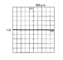
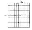
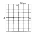
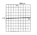
- FIG. 15A is a lateral aberration diagram of the coordinates [ ⁇ 10, ⁇ 10] of the test surface when scanning is performed in the Y direction by the two-dimensional scanning device in the second embodiment.
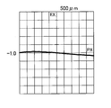
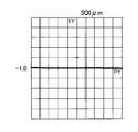
- FIG. 15B is a lateral aberration diagram of the coordinates [ ⁇ 10, ⁇ 10] of the test surface when scanning is performed in the X direction by the two-dimensional scanning device in the second embodiment.
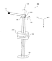
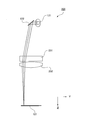
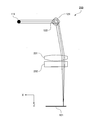
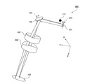
- FIG. 16 is a bird's-eye view of the two-dimensional scanning device in the third embodiment of the present invention.
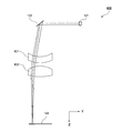
- FIG. 17 is a view of the two-dimensional scanning device in the third embodiment as viewed from the X direction.
- FIG. 18 is a view of the two-dimensional scanning device in the third embodiment as viewed from the Y direction.
- the first optical path represented by a dotted line is a light beam from the point light source at infinity through the toroidal lenses L1 and L2 and imaged on the image plane IP on the scanning plane side.
- the second optical path represented by a solid line is an optical path passing through the toroidal lenses L1 and L2 when the scanning mirror M1 or the scanning mirror M2 has an object point.
- the scanning mirror is the entrance pupil, and the position of the exit pupil is infinite.
- the lens unit including the toroidal lenses L1 and L2 constitutes an image side telecentric.
- Formula (5) is a numerical range that satisfies the conditions for solving these problems.
- optical elements constituting the two-dimensional scanning device 400 are shown in FIG.
- the respective values of the above formulas (1) to (8) calculated using the data of this specification table are shown in FIG.
- the mirror interval Dm affecting the difference between the focal length fx and the focal length fy is 50 mm.
- the working distance WD which affects the retro ratio and the telephoto ratio, is 60 mm. From the values shown in FIG. 27, it is found that the two-dimensional scanning device 400 satisfies the telecentric condition, the image point matching condition, and the beam spot condition regardless of the scanning direction.
Abstract
Description
(2)|f2x/f2y| > 1
以下、本発明に係わる実施の形態1について、図面を参照しながら説明する。
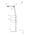
図1Aに示すように、二次元走査装置100は、被検面101を二次元に走査する装置である。ここでは、二次元走査装置100は、光源111、ミラー121,122、レンズ131,132を備える。
光源111は、X軸に平行に、波長1310nmの光を出力する。
ミラー121は、被検面101をX方向(第1方向)に走査する方向に光を屈折させるガルバノミラーである。ミラー122は、被検面101をY方向(第2方向)に走査する方向に光を屈折させるガルバノミラーである。ミラー121の中心とミラー122の中心とは、同一軸上に位置する。光源側111側にミラー121が配置されている。レンズ131側にミラー122が配置されている。ミラー121とミラー122との間には、各ミラーが衝突せずに回転可能な空間が確保されている。
レンズ131は、X方向とY方向とで曲率が異なり、X方向とY方向とで屈折力(パワー)が異なるトロイダルレンズである。レンズ132は、X方向とY方向とで曲率が異なり、X方向とY方向とで屈折力(パワー)が異なるトロイダルレンズである。レンズ131の向きは、レンズ131の光軸がZ軸と平行になるように調整されている。レンズ132の向きは、レンズ132の光軸がZ軸と平行になるように調整されている。レンズ131の光軸とレンズ132の光軸とは、同一軸上に位置する。ミラー122側にレンズ131が配置されている。被検面101側にレンズ132が配置されている。ミラー122で反射された光がレンズ131に入射する。レンズ131から射出された光がレンズ132に入射する。
次に、二次元走査装置100を構成する各光学素子の設計条件について説明する。


ここで、本実施の形態1の実施例について、図1A,図1B等を参照しながら説明する。レンズ131は、走査方向がX方向である場合の焦点距離f1xが53.45mmであり、走査方向がY方向である場合の焦点距離f1yが86.55mmである。レンズ132は、走査方向がX方向である場合の焦点距離f2xが-380.1mmであり、走査方向がY方向である場合の焦点距離f2yが159.54mmである。
以上、本実施の形態では、レンズ131,132にトロイダルレンズを採用している。そして、光源111から順に、ミラー121,122、レンズ131,132を配置している。このとき、ミラー121,122は、二次元平面上を走査可能なように配置している。また、レンズ131,132とは、隣接して配置している。これらの構成によって、歪が少なく、かつ簡易な構成でコンパクトな二次元走査装置を実現することができる。
以下、本発明に係わる実施の形態2について、図面を参照しながら説明する。
レンズ231は、X方向のみにパワーがあるシリンドリカルレンズである。レンズ232は、Y方向のみにパワーがあるシリンドリカルレンズである。
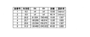
ここで、本実施の形態2の実施例について、図9等を用いて説明する。レンズ231は、走査方向がX方向である場合の焦点距離f1xが60.02mmであり、走査方向がY方向である場合の焦点距離f1yが無限大である。レンズ232は、走査方向がX方向である場合の焦点距離f2xが無限であり、走査方向がY方向である場合の焦点距離f2yが54.44mmである。

以上、本実施の形態では、レンズ231,232にシリンドリカルレンズを採用している。これによって、二次元の走査で得られる二次元像の歪が少なく、高精度な解像度を有し、かつ簡易な構成でコンパクトな二次元走査装置を実現することができる。本実施の形態2の二次元走査装置200は、前述の実施の形態1の二次元走査装置100と比べて、レンズの形状の自由度が増す。
以下、本発明に係わる実施の形態3について、図面を参照しながら説明する。
レンズ331は、X方向とY方向とでパワーが異なるトロイダルレンズである。レンズ332は、X方向とY方向とでパワーが異なるトロイダルレンズである。レンズ331の向きは、レンズ331の光軸がZ軸と平行になるように調整されている。レンズ332の向きは、レンズ332の光軸がZ軸と平行になるように調整されている。レンズ331の光軸とレンズ332の光軸とは、同一軸上に配置されている。
ここで、本実施の形態3の実施例について、図16等を参照しながら説明する。レンズ331は、走査方向がX方向である場合の焦点距離f1xが51.82mmであり、走査方向がY方向である場合の焦点距離f1yが83.98mmである。レンズ332は、走査方向がX方向である場合の焦点距離f2xが-413.17mmであり、走査方向がY方向である場合の焦点距離f2yが172.9mmである。
以上、本実施の形態3では、レンズ331,332に特殊な形状のトロイダルレンズを採用している。そのため、二次元の走査で得られる二次元像の歪が少なく、より高精度な解像度を有し、かつ簡易な構成でコンパクトな二次元走査装置を実現することができる。
以下、本発明に係わる実施の形態4について、図面を参照しながら説明する。
レンズ431は、X方向とY方向とでパワーが異なるトロイダルレンズである。レンズ432は、X方向とY方向とでパワーが異なるトロイダルレンズである。レンズ431の向きは、レンズ431の光軸がZ軸と平行になるように調整されている。レンズ432の向きは、レンズ432の光軸がZ軸と平行になるように調整されている。レンズ431の光軸とレンズ432の光軸とは、同一軸上に配置されている。レンズ431は、ミラー122側に配置している。レンズ432は、被検面101側に配置している。ミラー122で反射された光は、レンズ431に入射する。レンズ431から射出された光は、レンズ432に入射する。
ここで、本実施の形態4の実施例について、図23等を用いて説明する。レンズ431は、走査方向がX方向である場合の焦点距離f1xが47.9mmであり、走査方向がY方向である場合の焦点距離f1yが213.3mmである。レンズ432は、走査方向がX方向である場合の焦点距離f2xが-90.35mmであり、走査方向がY方向である場合の焦点距離f2yが85.96mmである。
以上、本実施の形態4では、レンズ431,432にトロイダルレンズを採用することで、二次元の走査で得られる二次元像の歪が少なく、高精度な解像度を有し、かつ簡易な構成でコンパクトな二次元走査装置を実現することができる。
Claims (11)
- 第1方向と、前記第1方向に直交する第2方向とに被検面を走査する二次元走査装置であって、
光源と、
前記光源からの光を前記被検面に対する前記第1方向および前記第2方向に走査させる走査光学系と、
前記第1方向と前記第2方向とでパワーが異なる第1レンズと、
前記第1方向と前記第2方向とでパワーが異なる第2レンズとを備え、
前記走査光学系は、前記第1レンズと前記第2レンズとからなるレンズ群より前記光源側に配置され、
走査方向が前記第1方向である場合の前記第1レンズの焦点距離をf1xとし、走査方向が前記第2方向である場合の前記第1レンズの焦点距離をf1yとし、走査方向が前記第1方向である場合の前記第2レンズの焦点距離をf2xとし、走査方向が前記第2方向である場合の前記第2レンズの焦点距離をf2yとしたとき、下記の式(1)および(2)を満たす
(1)|f1x/f1y| < 1
(2)|f2x/f2y| > 1
ことを特徴とする二次元走査装置。 - 前記第1レンズと前記第2レンズとが、トロイダルレンズである
ことを特徴とする請求項1に記載の二次元走査装置。 - 前記レンズ群が、前記第1方向と前記第2方向とのいずれか一方に前記被検面を走査する場合には、テレフォトタイプの光学系として機能し、他方に走査する場合には、レトロフォーカスタイプの光学系として機能する
ことを特徴とする請求項2に記載の二次元走査装置。 - 走査方向が前記第1方向である場合の前記レンズ群の焦点距離をfxとしたとき、
下記式(6)を満たす
(6)0.5 < f1x/fx < 1.4
ことを特徴とする請求項1に記載の二次元走査装置。 - 前記第1レンズと前記第2レンズとが、シリンドリカルレンズである
ことを特徴とする請求項1に記載の二次元走査装置。 - 前記第1レンズと前記第2レンズとの少なくとも1つが、入射面と射出面との少なくとも1つが非球面であるレンズである
ことを特徴とする請求項5に記載の二次元走査装置。 - 前記第1レンズと前記第2レンズとについて、入射面と射出面とのうち、レンズの曲率が大きい面が非球面である
ことを特徴とする請求項5に記載の二次元走査装置。 - 前記走査光学系が、前記被検面に対する前記第1方向を走査する第1ミラーと、前記被検面に対する前記第2方向を走査する第2ミラーとから構成された
ことを特徴とする請求項1に記載の二次元走査装置。 - 走査方向が前記第1方向である場合の前記レンズ群の焦点距離をfxとし、
走査方向が前記第2方向である場合の前記レンズ群の焦点距離をfyとし、
前記第1ミラーと前記第2ミラーとの間隔をDmとし、
前記第1レンズの射出面と前記第2レンズの入射面との光軸上の距離をDとし、
前記第2レンズの射出面から前記被検面までの光軸上の距離をWDとして、
下記の式(3)-(5)を満たす
(3)0.2 < |fx-fy|/Dm < 1.4
(4)0.6 < WD/fy < 1.4
(5)0.6 < (D+WD)/fx < 1.4
ことを特徴とする請求項8に記載の二次元走査装置。 - 下記の式(7)を満たす
(7)1.0 < fx/fy < 1.7
ことを特徴とする請求項9に記載の二次元走査装置。 - 下記の式(8)を満たす
(8)|(1/f1x+1/f2x)-(1/f1y+1/f2y)| < 0.02
ことを特徴とする請求項8に記載の二次元走査装置。
Priority Applications (1)
| Application Number | Priority Date | Filing Date | Title |
|---|---|---|---|
| US13/389,403 US8582190B2 (en) | 2010-04-30 | 2011-03-03 | Two-dimensional scanning device |
Applications Claiming Priority (2)
| Application Number | Priority Date | Filing Date | Title |
|---|---|---|---|
| JP2010104676A JP5268988B2 (ja) | 2010-04-30 | 2010-04-30 | 2次元走査装置 |
| JP2010-104676 | 2010-04-30 |
Publications (1)
| Publication Number | Publication Date |
|---|---|
| WO2011135771A1 true WO2011135771A1 (ja) | 2011-11-03 |
Family
ID=44861100
Family Applications (1)
| Application Number | Title | Priority Date | Filing Date |
|---|---|---|---|
| PCT/JP2011/001241 WO2011135771A1 (ja) | 2010-04-30 | 2011-03-03 | 二次元走査装置 |
Country Status (3)
| Country | Link |
|---|---|
| US (1) | US8582190B2 (ja) |
| JP (1) | JP5268988B2 (ja) |
| WO (1) | WO2011135771A1 (ja) |
Families Citing this family (3)
| Publication number | Priority date | Publication date | Assignee | Title |
|---|---|---|---|---|
| EP3236835A4 (en) * | 2014-12-23 | 2018-10-10 | Rebiscan, Inc. | Apparatus and method for fixation measurement with refraction error measurement using image sensing devices |
| JP6738417B2 (ja) | 2016-06-14 | 2020-08-12 | オリンパス株式会社 | 走査光学系および観察装置 |
| US11391822B2 (en) * | 2018-11-30 | 2022-07-19 | Seagate Technology Llc | Rotating pyramidal mirror |
Citations (4)
| Publication number | Priority date | Publication date | Assignee | Title |
|---|---|---|---|---|
| JP2709928B2 (ja) | 1987-12-23 | 1998-02-04 | 旭光学工業株式会社 | 二次元走査装置 |
| JP2004138822A (ja) * | 2002-10-17 | 2004-05-13 | Canon Inc | 網膜走査型表示装置 |
| JP2007253203A (ja) * | 2006-03-24 | 2007-10-04 | Sumitomo Electric Ind Ltd | レーザ加工用光学装置 |
| JP2010082663A (ja) * | 2008-09-30 | 2010-04-15 | Sunx Ltd | レーザ加工機 |
Family Cites Families (1)
| Publication number | Priority date | Publication date | Assignee | Title |
|---|---|---|---|---|
| US6887233B2 (en) * | 2001-03-22 | 2005-05-03 | Lumenis, Inc. | Scanning laser handpiece with shaped output beam |
-
2010
- 2010-04-30 JP JP2010104676A patent/JP5268988B2/ja not_active Expired - Fee Related
-
2011
- 2011-03-03 WO PCT/JP2011/001241 patent/WO2011135771A1/ja active Application Filing
- 2011-03-03 US US13/389,403 patent/US8582190B2/en active Active
Patent Citations (4)
| Publication number | Priority date | Publication date | Assignee | Title |
|---|---|---|---|---|
| JP2709928B2 (ja) | 1987-12-23 | 1998-02-04 | 旭光学工業株式会社 | 二次元走査装置 |
| JP2004138822A (ja) * | 2002-10-17 | 2004-05-13 | Canon Inc | 網膜走査型表示装置 |
| JP2007253203A (ja) * | 2006-03-24 | 2007-10-04 | Sumitomo Electric Ind Ltd | レーザ加工用光学装置 |
| JP2010082663A (ja) * | 2008-09-30 | 2010-04-15 | Sunx Ltd | レーザ加工機 |
Also Published As
| Publication number | Publication date |
|---|---|
| JP5268988B2 (ja) | 2013-08-21 |
| US20120134000A1 (en) | 2012-05-31 |
| JP2011232661A (ja) | 2011-11-17 |
| US8582190B2 (en) | 2013-11-12 |
Similar Documents
| Publication | Publication Date | Title |
|---|---|---|
| JP4890771B2 (ja) | 投写光学系およびこれを用いた投写型表示装置 | |
| JP4516114B2 (ja) | 撮像光学系 | |
| US6396640B2 (en) | Collimator lens and optical scanning apparatus using the same | |
| JP2563260B2 (ja) | 光ビ−ム走査装置 | |
| WO2012133623A1 (ja) | 走査型顕微鏡 | |
| JP3620767B2 (ja) | 反射型走査光学系 | |
| WO2011135771A1 (ja) | 二次元走査装置 | |
| US7463394B2 (en) | Linear optical scanner | |
| WO2013114725A1 (ja) | 立体視内視鏡光学系 | |
| JP4821057B2 (ja) | 軸外し反射光学系 | |
| US20090051995A1 (en) | Linear Optical Scanner | |
| JPH04131812A (ja) | 光ビーム走査装置 | |
| JP3339934B2 (ja) | f・θレンズ | |
| JP3713085B2 (ja) | 反射型走査光学系 | |
| EP1376196B1 (en) | Optical scanner comprising a compact f-theta lens with high cromatic aberration correctabilty | |
| US7554728B1 (en) | Modified gregorian astronomical telescope | |
| EP1376195B1 (en) | Optical scanner | |
| JP2945097B2 (ja) | テレセントリックなfθレンズ | |
| JP3034565B2 (ja) | テレセントリックなfθレンズ | |
| JP4174287B2 (ja) | 2次元走査装置及び画像表示装置 | |
| JP2000275557A (ja) | レーザー走査装置 | |
| JP2511904B2 (ja) | 光ビ−ム走査装置 | |
| WO2009107744A1 (ja) | 投影光学系および投影装置 | |
| CN213903934U (zh) | 一种远心激光场镜镜头及其激光扫描系统 | |
| JP2001281603A (ja) | コリメータレンズおよびこれを用いた光走査装置 |
Legal Events
| Date | Code | Title | Description |
|---|---|---|---|
| 121 | Ep: the epo has been informed by wipo that ep was designated in this application |
Ref document number: 11774562 Country of ref document: EP Kind code of ref document: A1 |
|
| WWE | Wipo information: entry into national phase |
Ref document number: 2011774562 Country of ref document: EP |
|
| WWE | Wipo information: entry into national phase |
Ref document number: 13389403 Country of ref document: US |
|
| NENP | Non-entry into the national phase |
Ref country code: DE |
|
| 122 | Ep: pct application non-entry in european phase |
Ref document number: 11774562 Country of ref document: EP Kind code of ref document: A1 |