WO2011129366A1 - 磁石用粉末 - Google Patents
磁石用粉末 Download PDFInfo
- Publication number
- WO2011129366A1 WO2011129366A1 PCT/JP2011/059183 JP2011059183W WO2011129366A1 WO 2011129366 A1 WO2011129366 A1 WO 2011129366A1 JP 2011059183 W JP2011059183 W JP 2011059183W WO 2011129366 A1 WO2011129366 A1 WO 2011129366A1
- Authority
- WO
- WIPO (PCT)
- Prior art keywords
- iron
- rare earth
- powder
- phase
- alloy
- Prior art date
- Legal status (The legal status is an assumption and is not a legal conclusion. Google has not performed a legal analysis and makes no representation as to the accuracy of the status listed.)
- Ceased
Links
Images
Classifications
-
- H—ELECTRICITY
- H01—ELECTRIC ELEMENTS
- H01F—MAGNETS; INDUCTANCES; TRANSFORMERS; SELECTION OF MATERIALS FOR THEIR MAGNETIC PROPERTIES
- H01F1/00—Magnets or magnetic bodies characterised by the magnetic materials therefor; Selection of materials for their magnetic properties
- H01F1/01—Magnets or magnetic bodies characterised by the magnetic materials therefor; Selection of materials for their magnetic properties of inorganic materials
- H01F1/03—Magnets or magnetic bodies characterised by the magnetic materials therefor; Selection of materials for their magnetic properties of inorganic materials characterised by their coercivity
- H01F1/032—Magnets or magnetic bodies characterised by the magnetic materials therefor; Selection of materials for their magnetic properties of inorganic materials characterised by their coercivity of hard-magnetic materials
- H01F1/04—Magnets or magnetic bodies characterised by the magnetic materials therefor; Selection of materials for their magnetic properties of inorganic materials characterised by their coercivity of hard-magnetic materials metals or alloys
- H01F1/047—Alloys characterised by their composition
- H01F1/053—Alloys characterised by their composition containing rare earth metals
- H01F1/055—Alloys characterised by their composition containing rare earth metals and magnetic transition metals, e.g. SmCo5
- H01F1/0551—Alloys characterised by their composition containing rare earth metals and magnetic transition metals, e.g. SmCo5 in the form of particles, e.g. rapid quenched powders or ribbon flakes
-
- B—PERFORMING OPERATIONS; TRANSPORTING
- B22—CASTING; POWDER METALLURGY
- B22F—WORKING METALLIC POWDER; MANUFACTURE OF ARTICLES FROM METALLIC POWDER; MAKING METALLIC POWDER; APPARATUS OR DEVICES SPECIALLY ADAPTED FOR METALLIC POWDER
- B22F1/00—Metallic powder; Treatment of metallic powder, e.g. to facilitate working or to improve properties
- B22F1/12—Metallic powder containing non-metallic particles
-
- B—PERFORMING OPERATIONS; TRANSPORTING
- B22—CASTING; POWDER METALLURGY
- B22F—WORKING METALLIC POWDER; MANUFACTURE OF ARTICLES FROM METALLIC POWDER; MAKING METALLIC POWDER; APPARATUS OR DEVICES SPECIALLY ADAPTED FOR METALLIC POWDER
- B22F3/00—Manufacture of workpieces or articles from metallic powder characterised by the manner of compacting or sintering; Apparatus specially adapted therefor ; Presses and furnaces
- B22F3/02—Compacting only
-
- B—PERFORMING OPERATIONS; TRANSPORTING
- B22—CASTING; POWDER METALLURGY
- B22F—WORKING METALLIC POWDER; MANUFACTURE OF ARTICLES FROM METALLIC POWDER; MAKING METALLIC POWDER; APPARATUS OR DEVICES SPECIALLY ADAPTED FOR METALLIC POWDER
- B22F3/00—Manufacture of workpieces or articles from metallic powder characterised by the manner of compacting or sintering; Apparatus specially adapted therefor ; Presses and furnaces
- B22F3/02—Compacting only
- B22F3/03—Press-moulding apparatus therefor
-
- B—PERFORMING OPERATIONS; TRANSPORTING
- B22—CASTING; POWDER METALLURGY
- B22F—WORKING METALLIC POWDER; MANUFACTURE OF ARTICLES FROM METALLIC POWDER; MAKING METALLIC POWDER; APPARATUS OR DEVICES SPECIALLY ADAPTED FOR METALLIC POWDER
- B22F3/00—Manufacture of workpieces or articles from metallic powder characterised by the manner of compacting or sintering; Apparatus specially adapted therefor ; Presses and furnaces
- B22F3/10—Sintering only
- B22F3/1003—Use of special medium during sintering, e.g. sintering aid
- B22F3/1007—Atmosphere
- B22F3/101—Changing atmosphere
-
- B—PERFORMING OPERATIONS; TRANSPORTING
- B22—CASTING; POWDER METALLURGY
- B22F—WORKING METALLIC POWDER; MANUFACTURE OF ARTICLES FROM METALLIC POWDER; MAKING METALLIC POWDER; APPARATUS OR DEVICES SPECIALLY ADAPTED FOR METALLIC POWDER
- B22F3/00—Manufacture of workpieces or articles from metallic powder characterised by the manner of compacting or sintering; Apparatus specially adapted therefor ; Presses and furnaces
- B22F3/24—After-treatment of workpieces or articles
-
- B—PERFORMING OPERATIONS; TRANSPORTING
- B22—CASTING; POWDER METALLURGY
- B22F—WORKING METALLIC POWDER; MANUFACTURE OF ARTICLES FROM METALLIC POWDER; MAKING METALLIC POWDER; APPARATUS OR DEVICES SPECIALLY ADAPTED FOR METALLIC POWDER
- B22F9/00—Making metallic powder or suspensions thereof
- B22F9/02—Making metallic powder or suspensions thereof using physical processes
- B22F9/023—Hydrogen absorption
-
- C—CHEMISTRY; METALLURGY
- C22—METALLURGY; FERROUS OR NON-FERROUS ALLOYS; TREATMENT OF ALLOYS OR NON-FERROUS METALS
- C22C—ALLOYS
- C22C33/00—Making ferrous alloys
- C22C33/02—Making ferrous alloys by powder metallurgy
- C22C33/0257—Making ferrous alloys by powder metallurgy characterised by the range of the alloying elements
- C22C33/0278—Making ferrous alloys by powder metallurgy characterised by the range of the alloying elements with at least one alloying element having a minimum content above 5%
-
- H—ELECTRICITY
- H01—ELECTRIC ELEMENTS
- H01F—MAGNETS; INDUCTANCES; TRANSFORMERS; SELECTION OF MATERIALS FOR THEIR MAGNETIC PROPERTIES
- H01F1/00—Magnets or magnetic bodies characterised by the magnetic materials therefor; Selection of materials for their magnetic properties
- H01F1/01—Magnets or magnetic bodies characterised by the magnetic materials therefor; Selection of materials for their magnetic properties of inorganic materials
- H01F1/03—Magnets or magnetic bodies characterised by the magnetic materials therefor; Selection of materials for their magnetic properties of inorganic materials characterised by their coercivity
- H01F1/032—Magnets or magnetic bodies characterised by the magnetic materials therefor; Selection of materials for their magnetic properties of inorganic materials characterised by their coercivity of hard-magnetic materials
- H01F1/04—Magnets or magnetic bodies characterised by the magnetic materials therefor; Selection of materials for their magnetic properties of inorganic materials characterised by their coercivity of hard-magnetic materials metals or alloys
- H01F1/047—Alloys characterised by their composition
- H01F1/053—Alloys characterised by their composition containing rare earth metals
-
- H—ELECTRICITY
- H01—ELECTRIC ELEMENTS
- H01F—MAGNETS; INDUCTANCES; TRANSFORMERS; SELECTION OF MATERIALS FOR THEIR MAGNETIC PROPERTIES
- H01F1/00—Magnets or magnetic bodies characterised by the magnetic materials therefor; Selection of materials for their magnetic properties
- H01F1/01—Magnets or magnetic bodies characterised by the magnetic materials therefor; Selection of materials for their magnetic properties of inorganic materials
- H01F1/03—Magnets or magnetic bodies characterised by the magnetic materials therefor; Selection of materials for their magnetic properties of inorganic materials characterised by their coercivity
- H01F1/032—Magnets or magnetic bodies characterised by the magnetic materials therefor; Selection of materials for their magnetic properties of inorganic materials characterised by their coercivity of hard-magnetic materials
- H01F1/04—Magnets or magnetic bodies characterised by the magnetic materials therefor; Selection of materials for their magnetic properties of inorganic materials characterised by their coercivity of hard-magnetic materials metals or alloys
- H01F1/047—Alloys characterised by their composition
- H01F1/053—Alloys characterised by their composition containing rare earth metals
- H01F1/055—Alloys characterised by their composition containing rare earth metals and magnetic transition metals, e.g. SmCo5
- H01F1/057—Alloys characterised by their composition containing rare earth metals and magnetic transition metals, e.g. SmCo5 and IIIa elements, e.g. Nd2Fe14B
- H01F1/0571—Alloys characterised by their composition containing rare earth metals and magnetic transition metals, e.g. SmCo5 and IIIa elements, e.g. Nd2Fe14B in the form of particles, e.g. rapid quenched powders or ribbon flakes
- H01F1/0575—Alloys characterised by their composition containing rare earth metals and magnetic transition metals, e.g. SmCo5 and IIIa elements, e.g. Nd2Fe14B in the form of particles, e.g. rapid quenched powders or ribbon flakes pressed, sintered or bonded together
- H01F1/0578—Alloys characterised by their composition containing rare earth metals and magnetic transition metals, e.g. SmCo5 and IIIa elements, e.g. Nd2Fe14B in the form of particles, e.g. rapid quenched powders or ribbon flakes pressed, sintered or bonded together bonded together
-
- H—ELECTRICITY
- H01—ELECTRIC ELEMENTS
- H01F—MAGNETS; INDUCTANCES; TRANSFORMERS; SELECTION OF MATERIALS FOR THEIR MAGNETIC PROPERTIES
- H01F1/00—Magnets or magnetic bodies characterised by the magnetic materials therefor; Selection of materials for their magnetic properties
- H01F1/01—Magnets or magnetic bodies characterised by the magnetic materials therefor; Selection of materials for their magnetic properties of inorganic materials
- H01F1/03—Magnets or magnetic bodies characterised by the magnetic materials therefor; Selection of materials for their magnetic properties of inorganic materials characterised by their coercivity
- H01F1/032—Magnets or magnetic bodies characterised by the magnetic materials therefor; Selection of materials for their magnetic properties of inorganic materials characterised by their coercivity of hard-magnetic materials
- H01F1/04—Magnets or magnetic bodies characterised by the magnetic materials therefor; Selection of materials for their magnetic properties of inorganic materials characterised by their coercivity of hard-magnetic materials metals or alloys
- H01F1/06—Magnets or magnetic bodies characterised by the magnetic materials therefor; Selection of materials for their magnetic properties of inorganic materials characterised by their coercivity of hard-magnetic materials metals or alloys in the form of particles, e.g. powder
-
- H—ELECTRICITY
- H01—ELECTRIC ELEMENTS
- H01F—MAGNETS; INDUCTANCES; TRANSFORMERS; SELECTION OF MATERIALS FOR THEIR MAGNETIC PROPERTIES
- H01F41/00—Apparatus or processes specially adapted for manufacturing or assembling magnets, inductances or transformers; Apparatus or processes specially adapted for manufacturing materials characterised by their magnetic properties
- H01F41/02—Apparatus or processes specially adapted for manufacturing or assembling magnets, inductances or transformers; Apparatus or processes specially adapted for manufacturing materials characterised by their magnetic properties for manufacturing cores, coils, or magnets
- H01F41/0253—Apparatus or processes specially adapted for manufacturing or assembling magnets, inductances or transformers; Apparatus or processes specially adapted for manufacturing materials characterised by their magnetic properties for manufacturing cores, coils, or magnets for manufacturing permanent magnets
- H01F41/0273—Imparting anisotropy
-
- H—ELECTRICITY
- H01—ELECTRIC ELEMENTS
- H01F—MAGNETS; INDUCTANCES; TRANSFORMERS; SELECTION OF MATERIALS FOR THEIR MAGNETIC PROPERTIES
- H01F1/00—Magnets or magnetic bodies characterised by the magnetic materials therefor; Selection of materials for their magnetic properties
- H01F1/01—Magnets or magnetic bodies characterised by the magnetic materials therefor; Selection of materials for their magnetic properties of inorganic materials
- H01F1/03—Magnets or magnetic bodies characterised by the magnetic materials therefor; Selection of materials for their magnetic properties of inorganic materials characterised by their coercivity
- H01F1/032—Magnets or magnetic bodies characterised by the magnetic materials therefor; Selection of materials for their magnetic properties of inorganic materials characterised by their coercivity of hard-magnetic materials
- H01F1/04—Magnets or magnetic bodies characterised by the magnetic materials therefor; Selection of materials for their magnetic properties of inorganic materials characterised by their coercivity of hard-magnetic materials metals or alloys
- H01F1/047—Alloys characterised by their composition
- H01F1/053—Alloys characterised by their composition containing rare earth metals
- H01F1/055—Alloys characterised by their composition containing rare earth metals and magnetic transition metals, e.g. SmCo5
- H01F1/057—Alloys characterised by their composition containing rare earth metals and magnetic transition metals, e.g. SmCo5 and IIIa elements, e.g. Nd2Fe14B
- H01F1/0571—Alloys characterised by their composition containing rare earth metals and magnetic transition metals, e.g. SmCo5 and IIIa elements, e.g. Nd2Fe14B in the form of particles, e.g. rapid quenched powders or ribbon flakes
- H01F1/0573—Alloys characterised by their composition containing rare earth metals and magnetic transition metals, e.g. SmCo5 and IIIa elements, e.g. Nd2Fe14B in the form of particles, e.g. rapid quenched powders or ribbon flakes obtained by reduction or by hydrogen decrepitation or embrittlement
-
- Y—GENERAL TAGGING OF NEW TECHNOLOGICAL DEVELOPMENTS; GENERAL TAGGING OF CROSS-SECTIONAL TECHNOLOGIES SPANNING OVER SEVERAL SECTIONS OF THE IPC; TECHNICAL SUBJECTS COVERED BY FORMER USPC CROSS-REFERENCE ART COLLECTIONS [XRACs] AND DIGESTS
- Y10—TECHNICAL SUBJECTS COVERED BY FORMER USPC
- Y10T—TECHNICAL SUBJECTS COVERED BY FORMER US CLASSIFICATION
- Y10T428/00—Stock material or miscellaneous articles
- Y10T428/29—Coated or structually defined flake, particle, cell, strand, strand portion, rod, filament, macroscopic fiber or mass thereof
- Y10T428/2982—Particulate matter [e.g., sphere, flake, etc.]
Definitions
- the present invention relates to a magnet powder used as a raw material for a rare earth-iron-boron magnet and a method for producing the same, a powder compact obtained from the powder, a rare earth-iron-boron alloy material, and a method for producing the same.
- the present invention relates to a magnet powder capable of forming a powder compact with excellent moldability and high relative density.
- Rare earth magnets are widely used as permanent magnets used in motors and generators.
- the rare earth magnet is typically a sintered magnet or a bond magnet made of an R—Fe—B alloy (R: rare earth element, Fe: iron, B: boron) such as Nd (neodymium) -Fe—B.
- Sintered magnets are manufactured by compressing and then sintering R-Fe-B alloy powder, and bonded magnets are a mixture of R-Fe-B alloy powder and binder resin.
- the mixture is produced by compression molding or injection molding.
- powders used in bonded magnets may be treated with HDRR (Hydrogenation-Disproportionation-Desorption-Recombination, HD: hydrogenation and disproportionation, DR: dehydrogenation and recombination) to increase the coercive force.
- HDRR Hydrodrogenation-Disproportionation-Desorption-Recombination
- HD hydrogenation and disproportionation
- DR dehydrogenation and recombination
- Sintered magnets have excellent magnetic properties due to their high magnetic phase ratio, but have a low degree of freedom in shape, for example, to form complex shapes such as cylindrical shapes, columnar shapes, and pot shapes (bottomed tubular shapes). In the case of a complicated shape, it is necessary to cut the sintered material. On the other hand, although a bonded magnet has a high degree of freedom in shape, it is inferior in magnet characteristics to a sintered magnet.
- Patent Document 1 the alloy powder made of the Nd-Fe-B alloy is made fine, and the green compact (powder compact) obtained by compression molding the alloy powder is subjected to the HDDR treatment. It is disclosed that a magnet having excellent magnet characteristics can be obtained in addition to increasing the degree of freedom of shape.
- the sintered magnet has excellent magnet characteristics, but the degree of freedom in shape is small.
- the degree of freedom in shape is high, but due to the presence of the binder resin, the ratio of the magnetic phase is at most 80% by volume. It is difficult to improve the ratio of the magnetic phase. Therefore, it is desired to develop a raw material for a rare earth magnet that has a high magnetic phase ratio and can be easily manufactured even in a complicated shape.
- An alloy powder made of an Nd-Fe-B alloy as disclosed in Patent Document 1 and a powder obtained by subjecting this alloy powder to HDDR treatment have high rigidity of particles constituting the powder and are difficult to be deformed. Therefore, in order to obtain a rare earth magnet having a high magnetic phase ratio without sintering, a powder compact having a high relative density is to be obtained by compression molding, which requires a relatively large pressure. In particular, if the particles constituting the alloy powder are coarse, a larger pressure is required. Therefore, it is desired to develop a raw material that can easily form a powder compact having a high relative density.
- the green compact when the green compact is subjected to the HDDR treatment, the green compact may be collapsed due to expansion and contraction of the green compact during the treatment. Therefore, it is desired to develop a raw material and a production method that are difficult to disintegrate during the production, have sufficient strength, and obtain a rare earth magnet having excellent magnetic properties.
- Another object of the present invention is to provide a powder compact suitable for a rare earth magnet material made of a rare earth-iron-boron alloy having excellent magnetic properties, a rare earth-iron-boron alloy material, and a method for producing the same. It is in.
- the present inventor uses a powder molded body rather than molding using a binding resin like a bonded magnet in order to obtain a magnet having excellent magnetic properties by increasing the ratio of the magnetic phase in the rare earth magnet without sintering.
- conventional raw material powders that is, alloy powders made of Nd-Fe-B alloys, and processed powders obtained by subjecting this alloy powder to HDDR treatment are hard, have low deformability, and are formed during compression molding. It is difficult to improve the density of the powder compact.
- the present inventors have found that the compound is not a state like a rare earth-iron-boron alloy, that is, a rare earth element and iron are not bonded, If the powder is a structure in which the element and iron do not bond, that is, the iron component or iron-boron alloy component is present independently of the rare earth element, the powder compact has high deformability, excellent formability, and high relative density.
- the powder having the specific structure can be produced by subjecting an alloy powder made of a rare earth-iron-boron alloy to a specific heat treatment.
- the magnet powder of the present invention is a powder used for rare earth magnets, each magnetic particle constituting the magnet powder is composed of a rare earth element hydrogen compound of less than 40% by volume, and the balance is composed of an iron-containing material. Yes.
- the iron-containing material includes iron and an iron-boron alloy containing iron and boron.
- the rare earth element hydrogen compound phase and the iron-containing substance phase are adjacent to each other, and the rare earth element hydrogen compound adjacent to each other through the iron-containing substance phase.
- the interval between the phases is 3 ⁇ m or less.
- the said magnet powder of this invention can be manufactured with the manufacturing method of the powder for magnets of the following this invention.
- This manufacturing method is a method for manufacturing a magnet powder used for a rare earth magnet, and includes the following preparation step and a hydrogenation step, and each magnetic particle constituting the magnet powder is less than 40% by volume.
- a rare earth element hydrogen compound and the balance comprising an iron-containing material, wherein the iron-containing material includes iron and an iron-boron alloy containing iron and boron, the rare earth element hydrogen compound phase and the iron-containing material And a gap between the phases of the hydrogen compounds of the rare earth elements adjacent to each other through the iron-containing material phase is 3 ⁇ m or less.
- Preparation step a step of preparing an alloy powder comprising a rare earth-iron-boron alloy.
- Hydrogenation step a step of producing the magnet powder by heat-treating the alloy powder at a temperature equal to or higher than the disproportionation temperature of the rare earth-iron-boron alloy in an atmosphere containing hydrogen element.
- Each magnetic particle constituting the magnet powder of the present invention is not composed of a single-phase rare earth alloy like an R-Fe-B alloy or an R-Fe-N alloy, but an iron-containing phase. And a plurality of phases composed of a rare earth element hydrogen compound.
- the phase of the iron-containing material is softer and more formable than the R-Fe-B alloy, the R-Fe-N alloy, and the rare earth element hydrogen compound.
- each magnetic particle constituting the magnet powder of the present invention has an iron-containing material containing iron as a main component (60% by volume or more), so that when the magnet powder of the present invention is compression molded, the magnetic particles The phase of the iron-containing material inside can be sufficiently deformed.
- the phase of the iron-containing material exists between the phases of the rare earth element hydride as described above, that is, the iron-containing material phase is not unevenly distributed in each magnetic particle constituting the powder. Therefore, the magnetic particles are uniformly deformed during compression molding.
- the magnetic particles are meshed with each other and bonded to each other, so that the ratio of the magnetic phase is 80% by volume or more, preferably without interposing a binding resin like a bonded magnet.
- a rare earth magnet of 90% by volume or more can be obtained.
- the powder compact obtained by compression-molding the magnet powder of the present invention does not sinter like a sintered magnet, there is no shape restriction due to the anisotropy of shrinkage that occurs during sintering. Great freedom. Therefore, by using the magnet powder of the present invention, for example, a complicated shape such as a cylindrical shape, a columnar shape, or a pot shape can be easily formed without substantially performing cutting or the like. Also, by eliminating the need for cutting, the yield of raw materials can be dramatically improved, and the productivity of rare earth magnets can be improved.
- the magnet powder of the present invention can be easily manufactured by heat-treating a rare earth-iron-boron alloy powder at a specific temperature in an atmosphere containing a hydrogen element.
- the magnet powder of the present invention can be made into a relatively coarse powder because of its excellent moldability as described above, and a coarse powder of about 100 ⁇ m can be used as the raw material powder. Therefore, in the production of the magnet powder of the present invention, for example, a powder produced by melting and casting ingot only by roughly pulverizing an average particle size of about 100 ⁇ m or a powder produced by an atomizing method (for example, a molten metal spraying method) is a raw material powder.
- sintered magnets and bonded magnets fine powders of 10 ⁇ m or less are used as raw material powders that form a green body before sintering and raw material powders mixed with resin.
- the magnet powder of the present invention uses the coarse powder as described above as a raw material, so that a fine pulverization step for making the raw material powder into a fine particle of 10 ⁇ m or less is unnecessary. Reduction can be achieved.
- the powder for magnets of the present invention is excellent in moldability and provides a powder compact of the present invention having a high relative density.
- a rare earth magnet having a high magnetic phase ratio can be obtained.
- the production method of the magnet powder of the present invention and the production method of the rare earth-iron-boron alloy material of the present invention can produce the above-mentioned magnet powder of the present invention and the rare earth-iron-boron alloy material of the present invention with high productivity. it can.
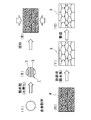
- FIG. 1 is a process explanatory view for explaining an example of a process for producing a magnet using the powder for magnet of the present invention.
- Each magnetic particle constituting the magnet powder of the present invention contains an iron-containing material as a main component, and the content thereof is 60% by volume or more.
- the content of iron-containing material is less than 60% by volume, the amount of hard rare earth element hydrogen compound is relatively large, and it is difficult to sufficiently deform the iron-containing component during compression molding. 90% by volume or less is preferable because it causes a decrease in magnetic properties.
- the iron-containing material includes both iron and an iron-boron alloy.
- the iron-boron alloy include Fe 3 B.
- the content of the iron-boron alloy is preferably 10% to 40% by mass when the iron content is 100%.
- the ratio of iron to the iron-boron alloy in the iron-containing material is obtained, for example, by measuring the peak intensity (peak area) of X-ray diffraction and comparing the measured peak intensity.
- the iron-containing material may have a form in which a part of iron is substituted with at least one element selected from Co, Ga, Cu, Al, Si, and Nb.
- the iron-containing material contains the above element, the magnetic properties and corrosion resistance of the rare earth magnet can be improved.
- the content is more than 0% by volume, preferably 10% by volume or more, and less than 40% by volume.
- the content of the iron-containing material or the rare earth element hydrogen compound, the ratio of iron and iron-boron alloy, the composition of the rare earth-iron-boron alloy used as the raw material of the powder, and the heat treatment conditions when producing the powder It can be adjusted mainly by changing the temperature) as appropriate.
- permits inclusion of an unavoidable impurity.
- the rare earth element contained in each magnetic particle constituting the magnet powder of the present invention is at least one element selected from Sc (scandium), Y (yttrium), lanthanoid and actinoid.
- the rare earth element hydrogen compound include NdH 2 and DyH 2 .
- Each magnetic particle constituting the magnet powder of the present invention has a structure in which both the rare earth element hydrogen compound phase and the iron-containing material phase are present at specific intervals as described above. It has a structure in which phases are present uniformly and discretely. Typically, a layered form in which both phases have a multilayer structure, a phase of the hydrogen compound of the rare earth element is granular, and the phase of the iron-containing material is a parent phase. A dispersion form in which a rare earth element hydrogen compound is dispersed may be mentioned.
- the presence form of both phases depends on the heat treatment conditions (mainly temperature) when producing the magnet powder of the present invention, and when the temperature is raised, it becomes a dispersed form, and when the temperature is in the vicinity of the disproportionation temperature, It tends to be a layered form.
- a rare earth magnet having a magnetic phase ratio comparable to that of a bonded magnet can be obtained without using a binder resin.
- the phase of the rare earth element hydrogen compound and the phase of the iron-containing material are adjacent to each other when the phase of the magnetic particles constituting the magnet powder is taken.
- the state of being laminated is the interval between the phases of the adjacent rare earth element hydrogen compounds.
- the interval between the phases of the adjacent rare earth element hydrogen compounds is the distance between the centers of the two rare earth element hydrogen compound phases adjacent to each other through the iron-containing material phase in the cross section.
- the dispersion form is such that the iron-containing component is uniformly present around the particles composed of the rare earth element hydrogen compound, so that the iron-containing component is more easily deformed than the layered form. It is easy to obtain a powder molded body having a complicated shape such as a columnar shape or a pot shape, or a high density powder molded body having a relative density of 85% or more, particularly 90% or more.
- the phase of the rare earth element hydrogen compound and the phase of the iron-containing material are typically adjacent to each other when the cross section of the magnetic particles constituting the magnet powder is taken.
- the iron-containing material exists so as to cover the periphery of the compound particles, and the iron-containing material exists between the adjacent hydrogen compound particles of each of the rare earth elements.
- the interval between phases of adjacent rare earth element hydrogen compounds refers to the distance between the centers of two adjacent rare earth element hydrogen compound particles in the cross section.
- the interval may be measured by, for example, etching the cross section to remove the iron-containing phase and extracting the rare earth element hydrogen compound, or removing the rare earth element hydrogen compound depending on the type of the solution. It can be measured by extracting an iron-containing material or by analyzing the composition of the cross section with an EDX (energy dispersive X-ray spectroscopy) apparatus.
- EDX energy dispersive X-ray spectroscopy
- the interval is preferably 0.5 ⁇ m or more, and more preferably 1 ⁇ m or more.
- the interval can be adjusted by adjusting the composition of the rare earth-iron-boron alloy powder used as a raw material, or by adjusting the heat treatment conditions when manufacturing the magnet powder, particularly the temperature. For example, in the rare earth-iron-boron-based alloy powder, when the ratio of iron or boron (atomic ratio) is increased or the temperature during the heat treatment (hydrogenation) is increased within the specific range, the interval increases. There is a tendency.
- the average particle size of the magnetic particles constituting the magnet powder of the present invention is particularly preferably 10 ⁇ m or more and 500 ⁇ m or less.
- occupancy ratio the ratio of the rare earth element hydrogen compound on the surface of each magnetic particle
- the rare earth elements are generally easily oxidized.
- the powder satisfying the average particle diameter is difficult to be oxidized due to the small occupation ratio and can be handled in the atmosphere. Therefore, for example, a powder molded body can be molded in the air, and the productivity of the powder molded body is excellent.
- the magnet powder of the present invention has an iron-containing phase as described above and is excellent in moldability.For example, even a coarse powder having an average particle size of 100 ⁇ m or more has few pores, A powder compact having a high relative density can be formed. However, if the average particle size is too large, the relative density of the powder compact is reduced, and therefore it is preferably 500 ⁇ m or less. The average particle size is more preferably 50 ⁇ m or more and 200 ⁇ m or less.
- the magnet powder according to the present invention may be provided with an insulating coating made of an insulating material on the outer periphery of each magnetic particle.
- an insulating coating made of an insulating material on the outer periphery of each magnetic particle.
- the crystalline coating, glass coating, oxide coating, ceramic coating, and the like may have an antioxidant function, and in this case, oxidation of magnetic particles can be prevented.
- Si-N or Si-C ceramic coating may be applied.
- a powder having a coating such as an insulating coating it is desirable that each magnetic particle constituting the powder has a nearly spherical shape in order to suppress damage to the coating during compression molding.
- rare earth magnets for example, a magnet powder from which a rare earth-iron-carbon alloy magnet can be obtained, a form in which the iron-containing material described above includes iron and an iron-carbon alloy containing iron and carbon can be mentioned. Similar to the powder containing the iron-boron alloy described above, the powder containing the iron-carbon alloy is obtained by changing the alloy powder made of a rare earth-iron-carbon alloy into the rare earth-iron-carbon system in an atmosphere containing a hydrogen element. It can be produced by heat treatment at a temperature equal to or higher than the disproportionation temperature of the alloy.
- iron-boron alloy or the rare earth-iron-boron alloy in each item described above and below can be replaced with an iron-carbon alloy or a rare earth-iron-carbon alloy.
- a typical rare earth-iron-carbon alloy is Nd 2 Fe 14 C.
- an alloy powder (for example, Nd 2 Fe 14 B) made of a rare earth-iron-boron alloy is prepared, and the alloy powder is heat-treated in an atmosphere containing hydrogen element to It is obtained by separating the rare earth element, iron and iron-boron alloy and combining the rare earth element and hydrogen.
- the alloy powder may be obtained by pulverizing a melt-cast ingot made of a rare earth-iron-boron alloy or a foil-like body obtained by a rapid solidification method using a crushing device such as a jaw crusher, a jet mill or a ball mill, or an atomizing method such as a gas atomizing method. It can be manufactured using the law.
- the gas atomization method when using the gas atomization method, by forming the powder in a non-oxidizing atmosphere, it is possible to obtain a powder containing substantially no oxygen (oxygen concentration: 1000 mass ppm or less, preferably 500 mass ppm or less). . That is, the fact that the oxygen concentration in the magnetic particles constituting the alloy powder is 1000 mass ppm or less can be one of indices indicating that the powder is produced by a gas atomizing method in a non-oxidizing atmosphere.
- the alloy powder made of the rare earth-iron-boron alloy a powder obtained by a known powder production method or a powder obtained by further pulverizing a powder produced by an atomization method may be used.
- each magnetic particle constituting the alloy powder may be a polycrystal or a single crystal.
- the magnetic particles made of a polycrystal can be appropriately heat treated to form particles made of a single crystal.
- the size of the alloy powder prepared in this preparation step is substantially the size of the magnet powder of the present invention when the heat treatment is performed so that the size is not substantially changed during the subsequent hydrogenation treatment. Become. Since the powder of the present invention is excellent in moldability as described above, for example, it can be made relatively coarse with an average particle diameter of about 100 ⁇ m. Therefore, in the preparation step, the alloy powder having an average particle size of about 100 ⁇ m can be used.
- the atmosphere containing hydrogen element examples include a single atmosphere containing only hydrogen (H 2 ) or a mixed atmosphere of hydrogen (H 2 ) and an inert gas such as Ar or N 2 .
- the temperature during the heat treatment in the hydrogenation step is set to a temperature at which the disproportionation reaction of the rare earth-iron-boron alloy proceeds, that is, the disproportionation temperature or higher.
- the disproportionation reaction is a reaction that separates rare earth element hydrogen compounds, iron, and iron-boron alloys by preferential hydrogenation of rare earth elements, and the lower limit temperature at which this reaction occurs is called the disproportionation temperature. .
- the disproportionation temperature varies depending on the composition of the alloy and the type of rare earth element.
- the temperature when the rare earth-iron-boron alloy is Nd 2 Fe 14 B, the temperature may be 650 ° C. or higher.
- the temperature during the heat treatment is close to the disproportionation temperature, the above-described layered form is obtained, and when the temperature is increased to the disproportionation temperature + 100 ° C. or higher, the above-described dispersion form is obtained.
- the higher the temperature during the heat treatment in the hydrogenation step the easier it is for the iron phase and iron-boron alloy phase to appear, and the hard rare earth element hydrogen compounds that precipitate at the same time are less likely to be a hindrance to deformation.
- the temperature is too high, problems such as melting and fixing of the powder occur.
- the temperature during the heat treatment is preferably 1100 ° C. or lower.
- the rare earth-iron-boron alloy is Nd 2 Fe 14 B
- the temperature during the heat treatment in the hydrogenation process is relatively low, such as 750 ° C. or more and 900 ° C. or less, the microstructure becomes small with a small interval.
- the holding time include 0.5 hours or more and 5 hours or less.
- the powder molded body of the present invention is obtained through a molding step in which the powder for magnet of the present invention is compression molded to form a powder molded body.
- a powder compact having a high relative density actual density relative to the true density of the powder compact
- one embodiment of the powder molded body of the present invention includes those having a relative density of 85% or more, and further 90% or more.
- a rare earth magnet having a high magnetic phase ratio can be obtained. Since the ratio of the magnetic phase is increased as the relative density is higher, there is no particular upper limit for the relative density.
- the magnet powder of the present invention is excellent in moldability, the pressure at the time of compression molding can be made relatively small, for example, from 8 ton / cm 2 to 15 ton / cm 2 . Furthermore, since the magnet powder of the present invention is excellent in moldability, it can be easily formed even if it is a powder compact having a complicated shape. In addition, the magnet powder of the present invention is excellent in bondability between magnetic particles because each magnetic particle constituting the powder can be sufficiently deformed (the strength (so-called necking strength) generated by the engagement of irregularities on the surface of the magnetic particles). Expression), a powder molded body having high strength and hardly disintegrating during production is obtained.
- the rare earth-iron-boron alloy material of the present invention can be obtained by combining iron, an iron-boron alloy, and a rare earth element from which hydrogen has been removed.
- the rare earth-iron-boron composite gold material of the present invention is substantially a single form composed of a rare earth-iron-boron alloy phase, substantially an iron phase, an iron-boron alloy phase, and a rare earth- Mixed form composed of a combination of at least one phase selected from iron alloy phases and a rare earth-iron-boron alloy phase (form having a mixed phase), for example, iron phase and rare earth-iron-boron system
- a rare earth-iron-boron alloy phase form having a mixed phase
- iron phase and rare earth-iron-boron system examples include the form of an alloy phase, the form of an iron-boron alloy phase and a rare earth-iron-boron alloy phase, and the form of a rare earth-iron alloy phase and a rare earth-iron-boron alloy phase.
- Examples of the single form include those having substantially the same composition as the rare earth-iron-boron alloy used as the raw material for the magnet powder of the present invention.
- the mixed form typically varies depending on the composition of the rare earth-iron-boron alloy used as a raw material. For example, when a material having a high iron ratio (atomic ratio) is used, the iron phase and the rare earth-iron-boron Forms with the alloy phase can be formed.
- non-hydrogen atmosphere examples include an inert atmosphere (for example, an inert gas atmosphere such as Ar or N 2 ) or a reduced pressure atmosphere (a vacuum atmosphere whose pressure is lower than the standard atmospheric pressure).
- the reduced-pressure atmosphere is preferable because the rare earth-iron-boron alloying is completely generated, rare earth hydrogen compounds hardly remain, and the rare earth-iron-boron alloy material of the present invention having excellent magnetic properties can be obtained.
- the final degree of vacuum is preferably 10 Pa or less.
- the temperature during the dehydrogenation treatment is not less than the recombination temperature of the powder compact (temperature at which the separated iron-containing material and rare earth element combine).
- the recombination temperature is typically 700 ° C. or higher although it varies depending on the composition of the powder compact (magnetic particles constituting the compact). The higher this temperature, the more hydrogen can be removed.
- the temperature during the dehydrogenation process is too high, the rare earth element having a high vapor pressure may volatilize and decrease, or the coercivity of the rare earth magnet may decrease due to the coarsening of the rare earth-iron-boron alloy crystal. Therefore, 1000 ° C. or less is preferable.
- the holding time is 10 minutes or more and 600 minutes (10 hours) or less.
- the heat treatment in the dehydrogenation step can be performed in a state where a magnetic field of 4 T or more is applied to the powder compact.
- the present inventors have found that when performing the heat treatment in the dehydrogenation step, a rare earth magnet having superior magnetic properties can be obtained by applying a strong magnetic field to the powder compact.
- the reason is considered as follows.
- the powder compact is simply subjected to dehydrogenation, the initial crystal nucleus composed of a rare earth-iron-boron alloy (for example, Nd 2 Fe 14 B) generated in the structure of the magnetic particles constituting the powder compact is,
- the heating temperature at the time of dehydrogenation is equal to or higher than the Curie point, and the direction of electrons is likely to be disturbed due to the influence of thermal disturbance (a state in which it tends to be random). Therefore, it is considered that a rare earth-iron-boron alloy material with random crystal directions can be obtained.
- the magnetic field used for magnetization (magnetization) of the rare earth magnet is about 2T.
- the degree of improvement in magnetic characteristics is small or not substantially improved.
- the applied magnetic field is preferably as high as possible, and is preferably 4T or more.
- the rare earth-iron-boron alloy material produced by heat-treating the above powder compact in an inert atmosphere or a reduced-pressure atmosphere with a magnetic field of 4 T or more applied has a certain orientation as described above. Show. Having a certain orientation means, for example, that in this rare earth-iron-boron alloy material, an X-ray diffraction pattern of a surface (hereinafter referred to as a normal surface) in which the application direction of the magnetic field is a normal direction is taken. In this case, the relative intensity of diffraction peaks appearing between crystal plane spacings of 0.202 nm to 0.204 nm satisfies 70 or more.
- the rare earth-iron-boron alloy material of the present invention in which the planes having the specific plane spacing are oriented is superior in magnetic properties. Moreover, the higher the relative strength is, the better the magnetic properties tend to be, and the relative strength is 75 or more.
- the relative intensity is the peak intensity of the diffraction peak that appears between the peak intensities of 0.202 nm to 0.204 nm with the maximum peak intensity among the peak intensities obtained from the normal plane as the reference intensity Imax. Is the measured intensity Ix, the ratio of the measured intensity Ix to the reference intensity Imax: (Ix / Imax) ⁇ 100.
- a rare earth magnet can be produced by appropriately magnetizing the rare earth-iron-boron alloy material of the present invention.
- a rare earth magnet having a magnetic phase ratio of 80% by volume or more, and further 90% by volume or more can be obtained.
- the above powder was prepared by the procedure of preparation step: preparation of alloy powder ⁇ hydrogenation step: heat treatment in hydrogen atmosphere. Further, the moldability was examined by preparing a powder produced by the above procedure and having an insulating coating formed thereon, and performing compression molding using this coated powder.
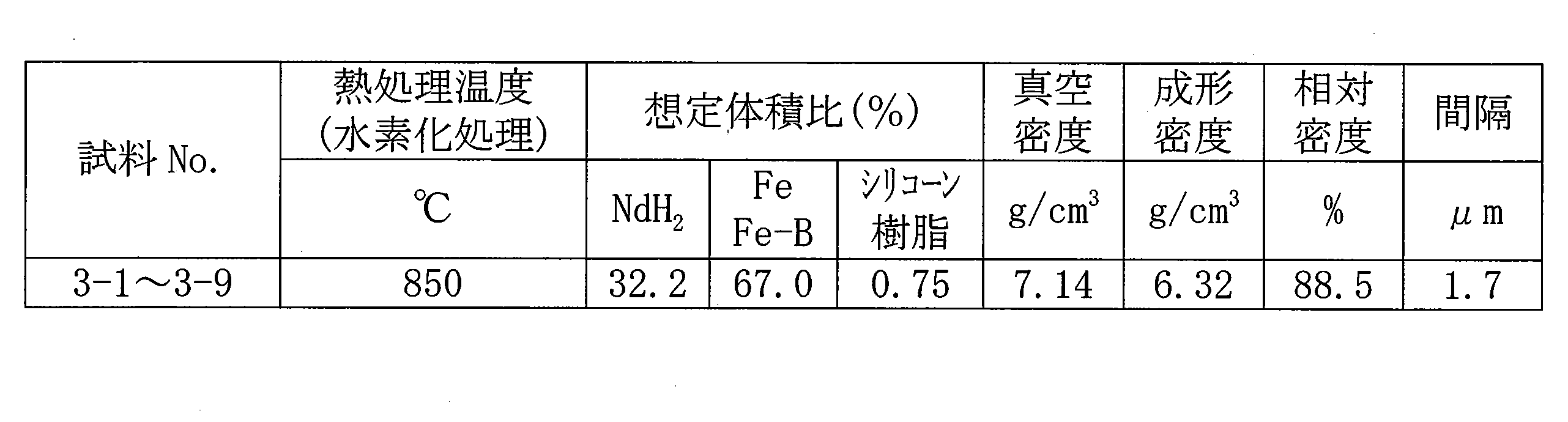
- the alloy powder was heat-treated in a hydrogen (H 2 ) atmosphere at 850 ° C. for 3 hours.
- the powder (magnet powder) obtained after this heat treatment (hydrogenation) was hardened with an epoxy resin to prepare a sample for observing the structure.
- the sample is cut or polished at an arbitrary position so that the powder inside the sample does not oxidize, and the composition of each particle constituting the magnet powder existing on the cut surface (or polished surface) is determined by an EDX apparatus. It was investigated by. Further, the cut surface (or polished surface) was observed with an optical microscope or an electron scanning microscope (100 to 10,000 times), and the form of each particle constituting the magnet powder was examined. Then, as shown in FIG.
- each magnetic particle 1 constituting the magnet powder is a phase 2 of iron-containing material (typically iron (Fe) and iron-boron alloy (Fe 3 B)).
- Phase 3 as a parent phase, and a plurality of granular rare earth element hydrogen compound phases 3 (typically NdH 2 ) are dispersed in the parent phase, and adjacent rare earth element hydrogen compounds It was confirmed that phase 2 of iron-containing material was present between the particles.
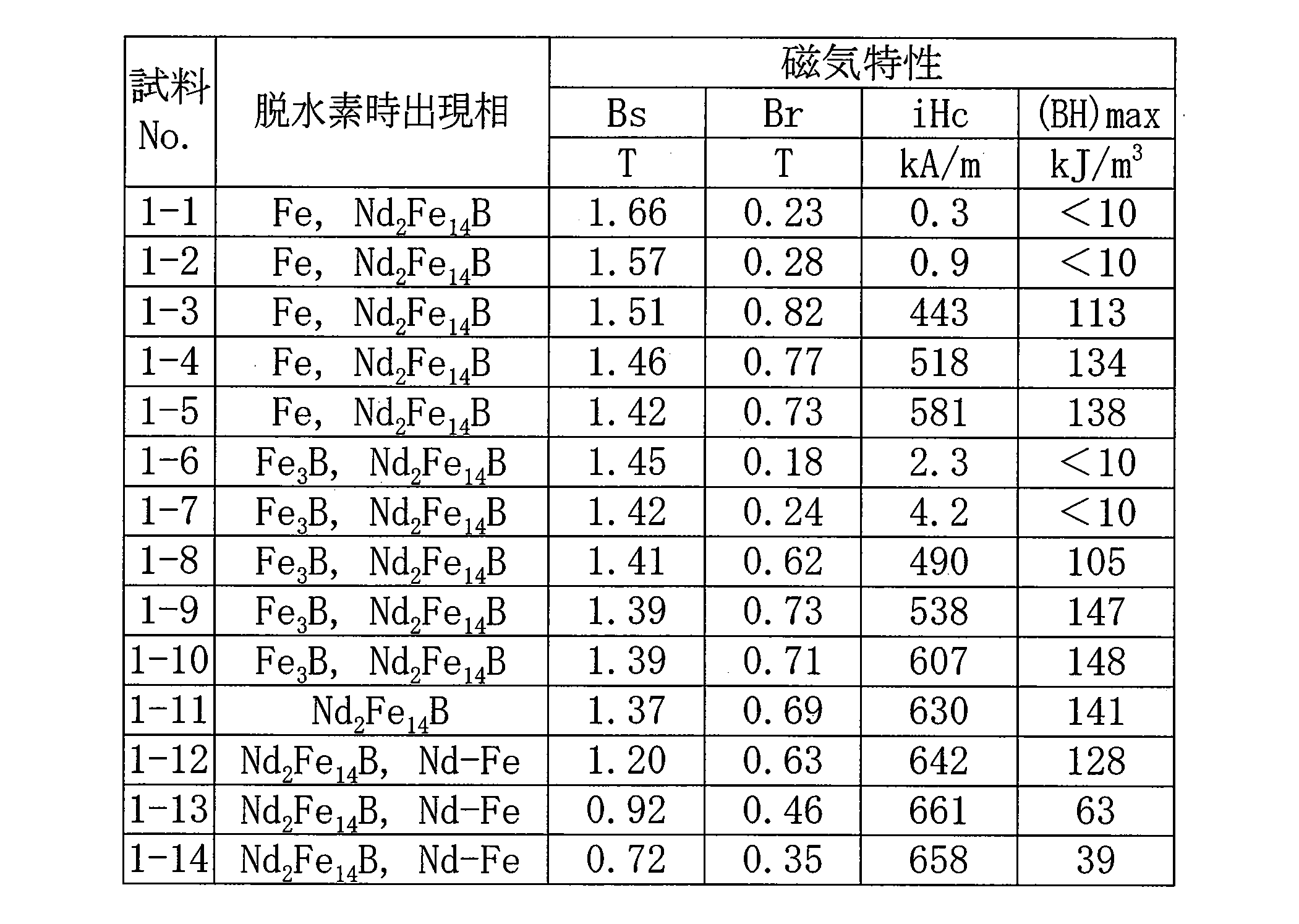
- the content (volume%) of rare earth element hydrogen compound: NdH 2 , iron-containing material: Fe, Fe—B of each magnetic particle was determined.
- the results are shown in Table 1.
- the above-mentioned content is based on the assumption that the later-described silicone resin is present in a certain volume ratio (0.75% by volume), the composition of the alloy powder used as the raw material, and the atomic weight of NdH 2 , Fe, Fe 3 B was used to calculate the volume ratio.
- the content is obtained, for example, by determining the area ratio of NdH 2 , Fe, Fe 3 B in the area of the cut surface (or polished surface) of the molded body produced using the magnet powder, respectively.
- the ratio can be obtained by converting the ratio into a volume ratio or by performing the X-ray analysis and utilizing the peak intensity ratio.
- the distance between adjacent rare earth element hydrogen compound particles was measured by the above-described EDX apparatus using surface analysis (mapping data) of the composition of each obtained powder.
- surface analysis was performed on the cut surface (or polished surface), the peak position of NdH 2 was extracted, the interval between the peak positions of adjacent NdH 2 was measured, and the average value of all the intervals was obtained. .
- Table 1 The results are shown in Table 1.
- a powder obtained by coating the magnet powder with a silicone resin as a precursor of the Si-O coating as an insulating coating was prepared, and the powder having the insulating coating was compression-molded by a hydraulic press device at a surface pressure of 10 ton / cm 2 . (Fig. 1 (III)).
- Fig. 1 (III) As a result, it was possible to sufficiently compress with a surface pressure of 10 ton / cm 2 except for sample No. 1-15, and to form a cylindrical powder compact 4 (Fig. 1 (IV)) with an outer diameter of 10mm ⁇ x height of 10mm. I was able to form. It is considered that Sample No. 1-15 had too few phases of iron-containing materials and was difficult to compress sufficiently and could not form a powder compact.
- the actual density (molding density) and relative density (actual density with respect to true density) of the obtained powder compact were determined. The results are shown in Table 1.
- the actual density was measured using a commercially available density measuring device.
- the true density is NdH 2 density: 5.96 g / cm 3
- Fe density 7.874 g / cm 3
- Fe 3 B density 7.474 g / cm 3
- silicone resin density 1.1 g / cm 3
- the volume ratio shown in 1 was used for calculation.
- the rare earth element hydrogen compound is less than 40% by volume, and the balance is substantially a powder containing iron such as Fe or Fe 3 B, and the rare earth element hydrogen compound is the iron-containing substance. It can be seen that a powder having a discrete structure (interval between phases: 3 ⁇ m or less) can obtain a powder compact having a complicated shape or a high density powder compact having a relative density of 85% or more. In particular, it can be seen that when a powder having a rare earth element hydrogen compound of less than 25% by volume is used, a powder compact having a higher density and a relative density of 90% or more can be easily obtained.
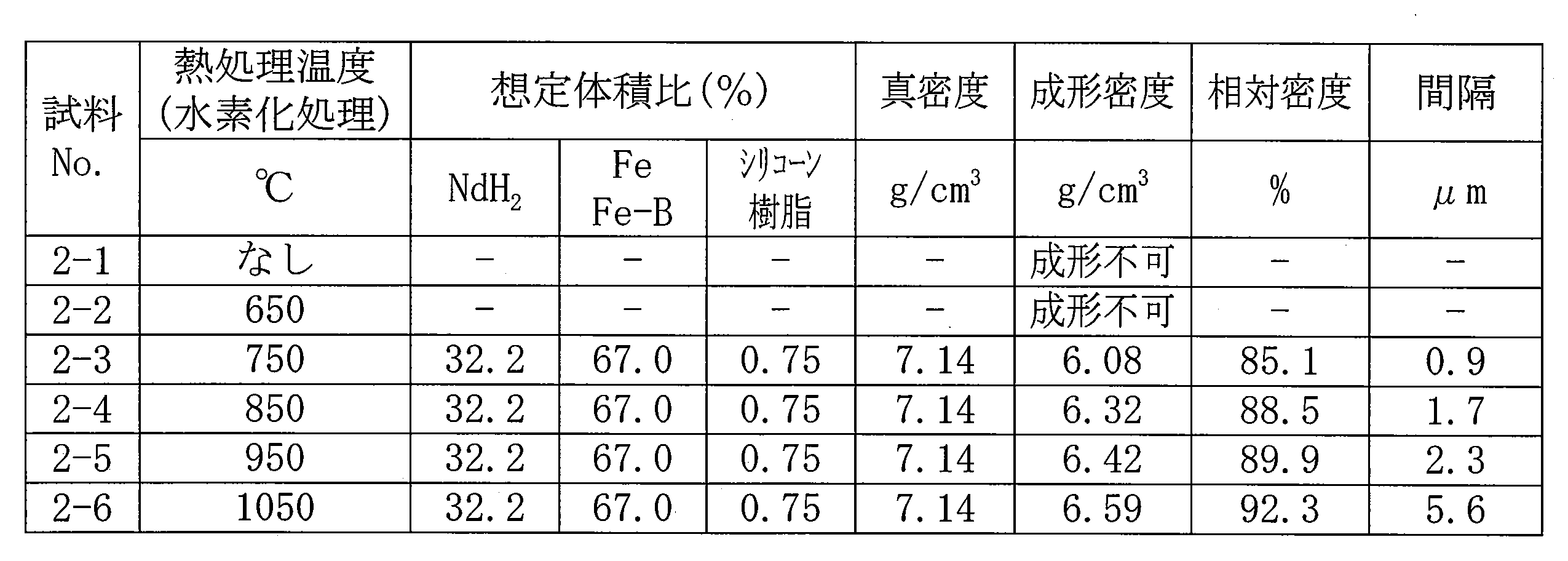
- the obtained powder compact was heated to 800 ° C. in an H 2 atmosphere, then switched to vacuum (VAC) and heat-treated in vacuum (VAC) (final vacuum degree: 5 Pa) at 800 ° C. ⁇ 10 min.
- VAC vacuum
- VAC heat-treated in vacuum
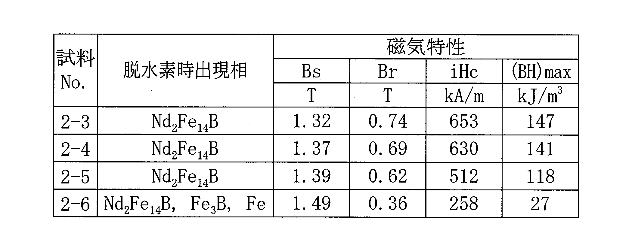
- the composition of the cylindrical member obtained after the heat treatment was examined by an EDX apparatus. The results are shown in Table 2. As shown in Table 2, each cylindrical member is made of a rare earth-iron-boron alloy material 5 (FIG.
- V substantially made of a rare earth-iron-boron alloy, or substantially (iron, Rare earth-iron-boron alloy), (iron-boron alloy, rare earth-iron-boron alloy), (rare earth-iron alloy, rare earth-iron-boron alloy) It can be seen that hydrogen was removed by the heat treatment.
- the rare earth element hydrogen compound of less than 40% by volume and the balance is substantially composed of iron-containing materials such as Fe and Fe 3 B, and the interval between adjacent rare earth element hydrogen compounds is 3 ⁇ m. It can be seen that rare earth magnets produced using the following powders (magnet powders) are excellent in magnetic properties. In particular, by using a powder with an iron-containing content of 90% by volume or less, or using a powder compact with a relative density of 85% or more, a rare earth magnet having excellent magnetic properties can be obtained without sintering. You can see that
- the rare earth element hydrogen compound of less than 40% by volume and the balance is substantially composed of iron-containing materials such as iron and iron-boron alloy, and the spacing between adjacent rare earth element hydrogen compound phases is
- a powder magnet powder
- the temperature during hydrogen treatment to a relatively low temperature
- a rare earth magnet having high coercive force and further excellent magnetic properties can be obtained without sintering. I understand that.
- a surface in which the magnetic field application direction during the dehydrogenation treatment is a normal direction is cut out as an observation surface, and alcohol is used so as not to oxidize the surface layer of the observation surface.
- An observation sample was prepared by polishing while being immersed in the substrate and removing processing distortion caused by cutting.
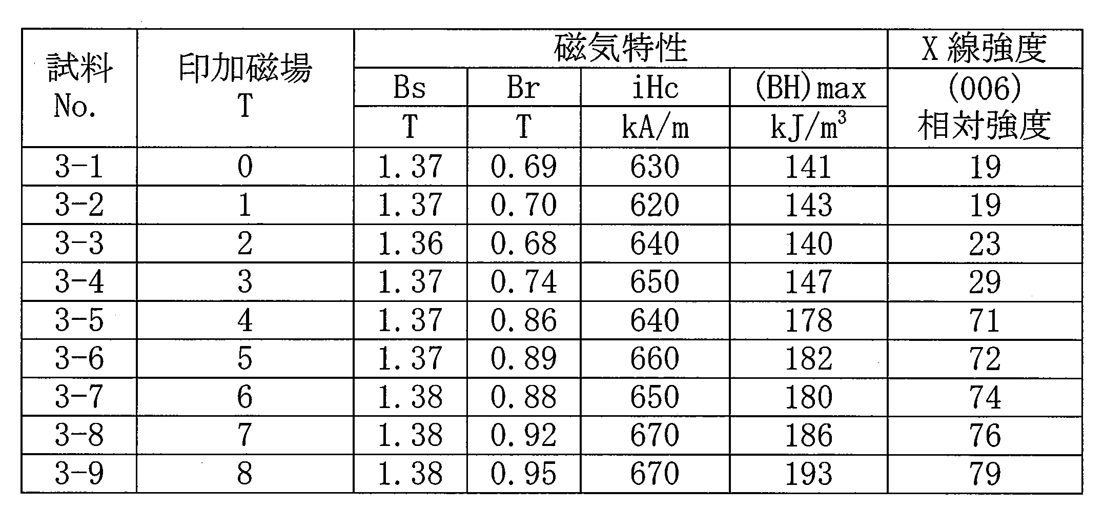
- the X-ray diffraction pattern of the Nd 2 Fe 14 B crystal was measured according to JIS K 0131 (1996) for the polished surface (observation surface) of each observation sample, and the maximum peak intensity of each observation sample : The reference intensity Imax was extracted.
- the peak intensity corresponding to the (006) plane (plane spacing: near 0.203 nm) is measured, and the peak intensity corresponding to this (006) plane is defined as the measured intensity Ix.
- the ratio (relative intensity) of the measured intensity Ix of the observed sample to the reference intensity Imax of the observed sample was determined as (Ix / Imax) ⁇ 100. The results are shown in Table 6.
- a rare-earth magnet having excellent magnetic properties can be obtained by performing a dehydrogenation process in a state where a magnetic field of 4 T or more is applied. It can also be seen that the larger the applied magnetic field, the better the magnetic properties. Furthermore, the obtained rare earth magnet has a large relative strength of 70 or more, has a certain orientation (here, the (006) plane is mainly oriented), and the relative strength increases as the applied magnetic field increases. I understand that.
- the above-described embodiment can be appropriately changed without departing from the gist of the present invention, and is not limited to the above-described configuration.
- the type of rare earth element, the average particle diameter of the magnet powder, the relative density of the powder compact, various heat treatment conditions (heating temperature, holding time), and the like can be appropriately changed.
- the magnet powder of the present invention, a powder compact obtained from this powder, and a rare earth-iron-boron alloy material are used in various motors, in particular, high-speed motors included in hybrid vehicles (HEV) and hard disk drives (HDD). It can be suitably used as a raw material or material for the permanent magnet used in the above.
- the method for producing the magnet powder of the present invention and the method of producing the rare earth-iron-boron alloy material of the present invention can be suitably used for the production of the magnet powder of the present invention and the rare earth-iron-boron alloy material of the present invention. it can.
Landscapes
- Engineering & Computer Science (AREA)
- Manufacturing & Machinery (AREA)
- Mechanical Engineering (AREA)
- Power Engineering (AREA)
- Chemical & Material Sciences (AREA)
- Crystallography & Structural Chemistry (AREA)
- Inorganic Chemistry (AREA)
- Materials Engineering (AREA)
- Metallurgy (AREA)
- Organic Chemistry (AREA)
- Hard Magnetic Materials (AREA)
- Powder Metallurgy (AREA)
- Manufacturing Cores, Coils, And Magnets (AREA)
Abstract
Description
準備工程:希土類-鉄-ホウ素系合金からなる合金粉末を準備する工程。
水素化工程:上記合金粉末を、水素元素を含む雰囲気中、上記希土類-鉄-ホウ素系合金の不均化温度以上の温度で熱処理して上記磁石用粉末を製造する工程。
[磁石用粉末]
本発明磁石用粉末を構成する各磁性粒子は、鉄含有物を主成分とし、その含有量を60体積%以上とする。鉄含有物の含有量が60体積%未満であると、硬質である希土類元素の水素化合物が相対的に多くなり、圧縮成形時、鉄含有物成分を十分に変形することが難しく、多過ぎると磁気特性の低下を招くことから90体積%以下が好ましい。
上記磁石用粉末は、希土類-鉄-ホウ素系合金からなる合金粉末(例えば、Nd2Fe14B)を用意し、この合金粉末を、水素元素を含む雰囲気中で熱処理して、上記合金中の希土類元素と鉄と鉄-ホウ素合金とを分離すると共に、当該希土類元素と水素とを化合することで得られる。上記合金粉末は、例えば、希土類-鉄-ホウ素系合金からなる溶解鋳造インゴットや急冷凝固法で得られる箔状体をジョークラッシャー、ジェットミルやボールミルなどの粉砕装置により粉砕したり、ガスアトマイズ法といったアトマイズ法を利用して製造することができる。特に、ガスアトマイズ法を利用する場合、非酸化性雰囲気で粉末を形成することで、実質的に酸素が含有されない粉末(酸素濃度:1000質量ppm以下、好ましくは500質量ppm以下)とすることができる。即ち、合金粉末を構成する磁性粒子中の酸素濃度が1000質量ppm以下であることは、非酸化性雰囲気のガスアトマイズ法により製造された粉末であることを示す指標の一つとなり得る。その他、上記希土類-鉄-ホウ素系合金からなる合金粉末には、公知の粉末の製造方法により得られたものやアトマイズ法により製造した粉末を更に粉砕したものを利用してもよい。粉砕条件や製造条件を適宜変更することで、磁石用粉末の粒度分布や磁性粒子の形状を調整することができる。例えば、アトマイズ法を利用すると、真球度が高く、成形時の充填性に優れた粉末が得られ易い。上記合金粉末を構成する各磁性粒子は多結晶体でも単結晶体でもよい。多結晶体からなる磁性粒子に適宜熱処理を加えて単結晶体からなる粒子とすることができる。
上記本発明磁石用粉末を圧縮成形して粉末成形体を成形する成形工程を経ることで、本発明粉末成形体が得られる。上述のように本発明磁石用粉末は、成形性に優れることから相対密度(粉末成形体の真密度に対する実際の密度)が高い粉末成形体を形成できる。例えば、本発明粉末成形体の一形態として、相対密度が85%以上、更には90%以上のものが挙げられる。このような高密度の粉末成形体を利用することで、磁性相の比率が高い希土類磁石が得られる。相対密度が高いほど、磁性相の比率が高められるため、相対密度の上限は特に設けない。
上記磁性粒子と反応せず、かつ水素を効率よく除去できるように非水素雰囲気にて、上記粉末成形体に熱処理(脱水素処理)を施す脱水素工程を経て、上記希土類元素の水素化合物から水素を除去すると共に、鉄と、鉄-ホウ素合金と、水素が除去された希土類元素とを化合することで、本発明希土類-鉄-ホウ素系合金材が得られる。本発明希土類-鉄-ホウ素合系金材は、実質的に、希土類-鉄-ホウ素系合金の相から構成される単一形態、実質的に、鉄相、鉄-ホウ素合金相、及び希土類-鉄合金相から選択される少なくとも一種の相と、希土類-鉄-ホウ素系合金の相との組み合わせで構成される混合形態(混相を具える形態)、例えば、鉄相と希土類-鉄-ホウ素系合金の相との形態、鉄-ホウ素合金相と希土類-鉄-ホウ素系合金の相との形態、希土類-鉄合金相と希土類-鉄-ホウ素系合金の相との形態が挙げられる。上記単一形態は、例えば、上記本発明磁石用粉末の原料に用いた希土類-鉄-ホウ素系合金と実質的に同じ組成からなるものが挙げられる。上記混合形態は、代表的には、原料に用いる希土類-鉄-ホウ素系合金の組成により変化し、例えば、鉄の比率(原子比)が高いものを用いると、鉄相と希土類-鉄-ホウ素合金の相との形態を形成することができる。
上記本発明希土類-鉄-ホウ素系合金材を適宜着磁することで、希土類磁石を製造できる。特に、上述した相対密度が高い粉末成形体を利用することで、磁性相の比率が80体積%以上、更に90体積%以上といった希土類磁石が得られる。
希土類元素と鉄とホウ素とを含む粉末を種々作製し、得られた粉末を圧縮成形して、各粉末の成形性を調べた。

試験例1と同様にして希土類磁石を作製し、磁気特性を調べた。
脱水素処理時の条件を変えて希土類磁石を作製し、磁気特性を調べた。
4 粉末成形体 5 希土類-鉄-ホウ素系合金材 6 希土類-鉄-ホウ素系合金磁石
Claims (12)
- 希土類磁石に用いられる磁石用粉末であって、
前記磁石用粉末を構成する各磁性粒子は、
40体積%未満の希土類元素の水素化合物と、残部が鉄含有物とからなり、
前記鉄含有物は、鉄と、鉄及びホウ素を含む鉄-ホウ素合金とを含み、
前記希土類元素の水素化合物の相と前記鉄含有物の相とが隣接して存在しており、
前記鉄含有物の相を介して隣り合う前記希土類元素の水素化合物の相間の間隔が3μm以下であることを特徴とする磁石用粉末。 - 前記希土類元素は、Nd,Pr,Ce,Dy,及びYから選択される少なくとも1種の元素を含むことを特徴とする請求項1に記載の磁石用粉末。
- 前記水素化合物の相は、粒状であり、
前記鉄含有物の相中に、前記粒状の希土類元素の水素化合物が分散して存在することを特徴とする請求項1又は2に記載の磁石用粉末。 - 前記磁性粒子の平均粒径が10μm以上500μm以下であることを特徴とする請求項1~3のいずれか1項に記載の磁石用粉末。
- 請求項1~4のいずれか1項に記載の磁石用粉末を圧縮成形して製造された粉末成形体であり、
前記粉末成形体の相対密度が85%以上であることを特徴とする粉末成形体。 - 請求項5に記載の粉末成形体を不活性雰囲気中、又は減圧雰囲気中で熱処理して製造されたことを特徴とする希土類-鉄-ホウ素系合金材。
- 請求項5に記載の粉末成形体を不活性雰囲気中、又は減圧雰囲気中で熱処理して製造され、鉄相、鉄-ホウ素合金相、及び希土類-鉄合金相から選択される少なくとも一種の相と、希土類-鉄-ホウ素合金相との混相材で構成されていることを特徴とする希土類-鉄-ホウ素系合金材。
- 請求項5に記載の粉末成形体に4T以上の磁界を印加した状態で不活性雰囲気中、又は減圧雰囲気中で熱処理を施して製造され、前記磁界の印加方向が法線方向となる面のX線回折パターンをとったとき、結晶面の面間隔が0.202nmから0.204nmの間に出現する回折ピークの相対強度が70以上であることを特徴とする希土類-鉄-ホウ素系合金材。
- 希土類磁石に用いられる磁石用粉末を製造する磁石用粉末の製造方法であって、
希土類-鉄-ホウ素系合金からなる合金粉末を準備する準備工程と、
前記合金粉末を、水素元素を含む雰囲気中、当該希土類-鉄-ホウ素系合金の不均化温度以上の温度で熱処理して前記磁石用粉末を製造する水素化工程とを具え、
前記磁石用粉末を構成する各磁性粒子は、40体積%未満の希土類元素の水素化合物と残部が鉄含有物とからなり、前記鉄含有物が鉄と、鉄及びホウ素を含む鉄-ホウ素合金とを含み、前記希土類元素の水素化合物の相と前記鉄含有物の相とが隣接して存在しており、かつ前記鉄含有物の相を介して隣り合う前記希土類元素の水素化合物の相間の間隔が3μm以下であることを特徴とする磁石用粉末の製造方法。 - 希土類磁石に用いられる希土類-鉄-ホウ素系合金材を製造する希土類-鉄-ホウ素系合金材の製造方法であって、
希土類-鉄-ホウ素系合金からなる合金粉末を準備する準備工程と、
前記合金粉末を、水素元素を含む雰囲気中、当該希土類-鉄-ホウ素系合金の不均化温度以上の温度で熱処理して、40体積%未満の希土類元素の水素化合物と残部が鉄含有物とからなり、前記鉄含有物が鉄と、鉄及びホウ素を含む鉄-ホウ素合金とを含み、前記希土類元素の水素化合物の相と前記鉄含有物の相とが隣接して存在しており、かつ前記鉄含有物の相を介して隣り合う前記希土類元素の水素化合物の相間の間隔が3μm以下である磁性粒子から構成される磁石用粉末を製造する水素化工程と、
前記磁石用粉末を圧縮成形して、相対密度が85%以上である粉末成形体を成形する成形工程と、
前記粉末成形体を不活性雰囲気中、又は減圧雰囲気中、当該粉末成形体の再結合温度以上の温度で熱処理して、希土類-鉄-ホウ素合金相を形成する脱水素工程とを具えることを特徴とする希土類-鉄-ホウ素系合金材の製造方法。 - 希土類磁石に用いられる希土類-鉄-ホウ素系合金材を製造する希土類-鉄-ホウ素系合金材の製造方法であって、
希土類-鉄-ホウ素系合金からなる合金粉末を準備する準備工程と、
前記合金粉末を、水素元素を含む雰囲気中、当該希土類-鉄-ホウ素系合金の不均化温度以上の温度で熱処理して、40体積%未満の希土類元素の水素化合物と残部が鉄含有物とからなり、前記鉄含有物が鉄と、鉄及びホウ素を含む鉄-ホウ素合金とを含み、前記希土類元素の水素化合物の相と前記鉄含有物の相とが隣接して存在しており、かつ前記鉄含有物の相を介して隣り合う前記希土類元素の水素化合物の相間の間隔が3μm以下である磁性粒子から構成される磁石用粉末を製造する水素化工程と、
前記磁石用粉末を圧縮成形して、相対密度が85%以上である粉末成形体を成形する成形工程と、
前記粉末成形体を不活性雰囲気中、又は減圧雰囲気中、当該粉末成形体の再結合温度以上の温度で熱処理して、鉄相、鉄-ホウ素合金相、及び希土類-鉄合金相から選択される少なくとも一種の相と、希土類-鉄-ホウ素合金相との混相を形成する脱水素工程とを具えることを特徴とする希土類-鉄-ホウ素系合金材の製造方法。 - 前記脱水素工程の熱処理は、前記粉末成形体に4T以上の磁界を印加した状態で行うことを特徴とする請求項10又は11に記載の希土類-鉄-ホウ素系合金材の製造方法。
Priority Applications (5)
| Application Number | Priority Date | Filing Date | Title |
|---|---|---|---|
| EP11768887.9A EP2481502B1 (en) | 2010-04-15 | 2011-04-13 | Powder for magnet |
| CN201180003841.2A CN102510782B (zh) | 2010-04-15 | 2011-04-13 | 磁体用粉末 |
| KR1020127005937A KR101345496B1 (ko) | 2010-04-15 | 2011-04-13 | 자석용 분말, 분말 성형체, 희토류-철-붕소계 합금재, 자석용 분말의 제조 방법, 및 희토류-철-붕소계 합금재의 제조 방법 |
| US13/496,069 US9314843B2 (en) | 2010-04-15 | 2011-04-13 | Powder for magnet |
| US15/044,861 US9460836B2 (en) | 2010-04-15 | 2016-02-16 | Powder for magnet |
Applications Claiming Priority (4)
| Application Number | Priority Date | Filing Date | Title |
|---|---|---|---|
| JP2010093875 | 2010-04-15 | ||
| JP2010-093875 | 2010-04-15 | ||
| JP2011036281A JP5059955B2 (ja) | 2010-04-15 | 2011-02-22 | 磁石用粉末 |
| JP2011-036281 | 2011-02-22 |
Related Child Applications (2)
| Application Number | Title | Priority Date | Filing Date |
|---|---|---|---|
| US13/496,069 A-371-Of-International US9314843B2 (en) | 2010-04-15 | 2011-04-13 | Powder for magnet |
| US15/044,861 Division US9460836B2 (en) | 2010-04-15 | 2016-02-16 | Powder for magnet |
Publications (1)
| Publication Number | Publication Date |
|---|---|
| WO2011129366A1 true WO2011129366A1 (ja) | 2011-10-20 |
Family
ID=44798737
Family Applications (1)
| Application Number | Title | Priority Date | Filing Date |
|---|---|---|---|
| PCT/JP2011/059183 Ceased WO2011129366A1 (ja) | 2010-04-15 | 2011-04-13 | 磁石用粉末 |
Country Status (7)
| Country | Link |
|---|---|
| US (2) | US9314843B2 (ja) |
| EP (1) | EP2481502B1 (ja) |
| JP (1) | JP5059955B2 (ja) |
| KR (1) | KR101345496B1 (ja) |
| CN (1) | CN102510782B (ja) |
| TW (1) | TW201142878A (ja) |
| WO (1) | WO2011129366A1 (ja) |
Cited By (1)
| Publication number | Priority date | Publication date | Assignee | Title |
|---|---|---|---|---|
| JP2013110225A (ja) * | 2011-11-18 | 2013-06-06 | Sumitomo Electric Ind Ltd | 磁性部材及びその製造方法 |
Families Citing this family (9)
| Publication number | Priority date | Publication date | Assignee | Title |
|---|---|---|---|---|
| JP6098786B2 (ja) * | 2012-09-21 | 2017-03-22 | 住友電気工業株式会社 | 複合材料、リアクトル、コンバータ、及び電力変換装置 |
| CN103050267B (zh) * | 2012-12-31 | 2016-01-20 | 厦门钨业股份有限公司 | 一种基于细粉热处理的烧结Nd-Fe-B系磁铁制作方法 |
| DE102013205280A1 (de) * | 2013-03-26 | 2014-10-02 | Siemens Aktiengesellschaft | Permanentmagnet und Verfahren zur Herstellung des Permanentmagneten |
| JP2015079925A (ja) * | 2013-10-18 | 2015-04-23 | 住友電気工業株式会社 | 希土類磁石の製造方法 |
| CN106133157A (zh) * | 2014-03-28 | 2016-11-16 | 日立金属株式会社 | 稀土元素的回收方法 |
| WO2015152048A1 (ja) * | 2014-03-31 | 2015-10-08 | Dowaエレクトロニクス株式会社 | Fe-Co合金粉末およびその製造方法並びにアンテナ、インダクタおよびEMIフィルタ |
| JP6447804B2 (ja) * | 2014-05-16 | 2019-01-09 | 住友電気工業株式会社 | 磁石用成形体の製造方法 |
| KR102033910B1 (ko) * | 2017-09-12 | 2019-11-18 | 슝크카본테크놀로지유한회사 | 전동차 Trolley wire 습동용 집전소재 및 그 제조방법 |
| JP7460032B2 (ja) * | 2022-03-25 | 2024-04-02 | Jfeスチール株式会社 | 脱水素装置及び鋼板の製造システム、並びに鋼板の製造方法 |
Citations (2)
| Publication number | Priority date | Publication date | Assignee | Title |
|---|---|---|---|---|
| WO2005105343A1 (ja) * | 2004-04-30 | 2005-11-10 | Neomax Co., Ltd. | 希土類磁石用原料合金および粉末ならびに焼結磁石の製造方法 |
| JP2009123968A (ja) | 2007-11-15 | 2009-06-04 | Hitachi Metals Ltd | R−Fe−B系永久磁石用多孔質材料およびその製造方法 |
Family Cites Families (17)
| Publication number | Priority date | Publication date | Assignee | Title |
|---|---|---|---|---|
| CH515763A (de) | 1969-07-10 | 1971-11-30 | Bbc Brown Boveri & Cie | Verfahren zur Herstellung von Dauermagneten |
| JPS5378096A (en) | 1976-12-20 | 1978-07-11 | Hitachi Maxell | Magnetic metal powder for magnetic recording and method of manufacturing same |
| JP2576671B2 (ja) | 1989-07-31 | 1997-01-29 | 三菱マテリアル株式会社 | 磁気的異方性および耐食性に優れた希土類ーFeーB系永久磁石粉末およびボンド磁石 |
| US5474623A (en) | 1993-05-28 | 1995-12-12 | Rhone-Poulenc Inc. | Magnetically anisotropic spherical powder and method of making same |
| JPH07245206A (ja) * | 1994-03-04 | 1995-09-19 | Tokin Corp | 希土類永久磁石用粉末及びその製造方法 |
| JPH10106875A (ja) | 1996-09-30 | 1998-04-24 | Tokin Corp | 希土類磁石の製造方法 |
| JPH11158588A (ja) * | 1997-09-26 | 1999-06-15 | Mitsubishi Materials Corp | 希土類磁石粉末製造用原料合金およびその製造方法 |
| CN1144240C (zh) | 1998-03-27 | 2004-03-31 | 东芝株式会社 | 磁性材料 |
| US6444052B1 (en) | 1999-10-13 | 2002-09-03 | Aichi Steel Corporation | Production method of anisotropic rare earth magnet powder |
| JP3452254B2 (ja) | 2000-09-20 | 2003-09-29 | 愛知製鋼株式会社 | 異方性磁石粉末の製造方法、異方性磁石粉末の原料粉末およびボンド磁石 |
| JP4648586B2 (ja) | 2001-07-16 | 2011-03-09 | 昭和電工株式会社 | 希土類焼結磁石の製造方法および希土類焼結磁石 |
| JP4029714B2 (ja) | 2002-10-10 | 2008-01-09 | 日産自動車株式会社 | 高保磁力異方性磁石及びその製造方法 |
| JP2008172037A (ja) | 2007-01-12 | 2008-07-24 | Daido Steel Co Ltd | 希土類磁石及びその製造方法 |
| JP2008170814A (ja) | 2007-01-12 | 2008-07-24 | Sharp Corp | 現像剤 |
| US20100279105A1 (en) | 2009-04-15 | 2010-11-04 | Arizona Board Of Regents On Behalf Of The University Of Arizona | Coated Magnetic Particles, Composite Magnetic Materials and Magnetic Tapes Using Them |
| CN101615459B (zh) | 2009-04-28 | 2011-11-23 | 中国科学院宁波材料技术与工程研究所 | 提高烧结钕铁硼永磁材料性能的方法 |
| JP5059929B2 (ja) | 2009-12-04 | 2012-10-31 | 住友電気工業株式会社 | 磁石用粉末 |
-
2011
- 2011-02-22 JP JP2011036281A patent/JP5059955B2/ja not_active Expired - Fee Related
- 2011-04-13 CN CN201180003841.2A patent/CN102510782B/zh not_active Expired - Fee Related
- 2011-04-13 EP EP11768887.9A patent/EP2481502B1/en not_active Not-in-force
- 2011-04-13 WO PCT/JP2011/059183 patent/WO2011129366A1/ja not_active Ceased
- 2011-04-13 US US13/496,069 patent/US9314843B2/en not_active Expired - Fee Related
- 2011-04-13 KR KR1020127005937A patent/KR101345496B1/ko not_active Expired - Fee Related
- 2011-04-14 TW TW100113033A patent/TW201142878A/zh unknown
-
2016
- 2016-02-16 US US15/044,861 patent/US9460836B2/en not_active Expired - Fee Related
Patent Citations (2)
| Publication number | Priority date | Publication date | Assignee | Title |
|---|---|---|---|---|
| WO2005105343A1 (ja) * | 2004-04-30 | 2005-11-10 | Neomax Co., Ltd. | 希土類磁石用原料合金および粉末ならびに焼結磁石の製造方法 |
| JP2009123968A (ja) | 2007-11-15 | 2009-06-04 | Hitachi Metals Ltd | R−Fe−B系永久磁石用多孔質材料およびその製造方法 |
Cited By (1)
| Publication number | Priority date | Publication date | Assignee | Title |
|---|---|---|---|---|
| JP2013110225A (ja) * | 2011-11-18 | 2013-06-06 | Sumitomo Electric Ind Ltd | 磁性部材及びその製造方法 |
Also Published As
| Publication number | Publication date |
|---|---|
| US20160180992A1 (en) | 2016-06-23 |
| EP2481502A1 (en) | 2012-08-01 |
| KR20120054047A (ko) | 2012-05-29 |
| EP2481502A4 (en) | 2017-08-02 |
| TW201142878A (en) | 2011-12-01 |
| CN102510782B (zh) | 2014-12-17 |
| JP2011236498A (ja) | 2011-11-24 |
| US9314843B2 (en) | 2016-04-19 |
| CN102510782A (zh) | 2012-06-20 |
| JP5059955B2 (ja) | 2012-10-31 |
| KR101345496B1 (ko) | 2013-12-27 |
| EP2481502B1 (en) | 2019-02-27 |
| US20120237769A1 (en) | 2012-09-20 |
| US9460836B2 (en) | 2016-10-04 |
Similar Documents
| Publication | Publication Date | Title |
|---|---|---|
| JP5059955B2 (ja) | 磁石用粉末 | |
| JP5218869B2 (ja) | 希土類−鉄−窒素系合金材、希土類−鉄−窒素系合金材の製造方法、希土類−鉄系合金材、及び希土類−鉄系合金材の製造方法 | |
| JP5059929B2 (ja) | 磁石用粉末 | |
| EP2484464B1 (en) | Powder for magnetic member, powder compact, and magnetic member | |
| CN106898450A (zh) | 稀土磁体 | |
| JP2013102122A (ja) | 磁性部材及び磁性部材の製造方法 | |
| JP2014192460A (ja) | R−t−x系圧粉磁石の製造方法、及びr−t−x系圧粉磁石 | |
| JP5051270B2 (ja) | 磁性部材用粉末、粉末成形体、及び磁性部材 | |
| JP4930813B2 (ja) | 磁性部材用粉末、粉末成形体、及び磁性部材 | |
| JP6447804B2 (ja) | 磁石用成形体の製造方法 | |
| JP2012186212A (ja) | 磁性部材の製造方法及び磁性部材 |
Legal Events
| Date | Code | Title | Description |
|---|---|---|---|
| WWE | Wipo information: entry into national phase |
Ref document number: 201180003841.2 Country of ref document: CN |
|
| 121 | Ep: the epo has been informed by wipo that ep was designated in this application |
Ref document number: 11768887 Country of ref document: EP Kind code of ref document: A1 |
|
| ENP | Entry into the national phase |
Ref document number: 20127005937 Country of ref document: KR Kind code of ref document: A |
|
| WWE | Wipo information: entry into national phase |
Ref document number: 2011768887 Country of ref document: EP |
|
| WWE | Wipo information: entry into national phase |
Ref document number: 13496069 Country of ref document: US |
|
| NENP | Non-entry into the national phase |
Ref country code: DE |