WO2011129342A1 - ミリ波撮像装置 - Google Patents
ミリ波撮像装置 Download PDFInfo
- Publication number
- WO2011129342A1 WO2011129342A1 PCT/JP2011/059107 JP2011059107W WO2011129342A1 WO 2011129342 A1 WO2011129342 A1 WO 2011129342A1 JP 2011059107 W JP2011059107 W JP 2011059107W WO 2011129342 A1 WO2011129342 A1 WO 2011129342A1
- Authority
- WO
- WIPO (PCT)
- Prior art keywords
- subject
- thermal noise
- millimeter
- antenna
- image
- Prior art date
- Legal status (The legal status is an assumption and is not a legal conclusion. Google has not performed a legal analysis and makes no representation as to the accuracy of the status listed.)
- Ceased
Links
Images

Classifications
-
- G—PHYSICS
- G01—MEASURING; TESTING
- G01S—RADIO DIRECTION-FINDING; RADIO NAVIGATION; DETERMINING DISTANCE OR VELOCITY BY USE OF RADIO WAVES; LOCATING OR PRESENCE-DETECTING BY USE OF THE REFLECTION OR RERADIATION OF RADIO WAVES; ANALOGOUS ARRANGEMENTS USING OTHER WAVES
- G01S13/00—Systems using the reflection or reradiation of radio waves, e.g. radar systems; Analogous systems using reflection or reradiation of waves whose nature or wavelength is irrelevant or unspecified
- G01S13/88—Radar or analogous systems specially adapted for specific applications
- G01S13/887—Radar or analogous systems specially adapted for specific applications for detection of concealed objects, e.g. contraband or weapons
-
- G—PHYSICS
- G01—MEASURING; TESTING
- G01S—RADIO DIRECTION-FINDING; RADIO NAVIGATION; DETERMINING DISTANCE OR VELOCITY BY USE OF RADIO WAVES; LOCATING OR PRESENCE-DETECTING BY USE OF THE REFLECTION OR RERADIATION OF RADIO WAVES; ANALOGOUS ARRANGEMENTS USING OTHER WAVES
- G01S13/00—Systems using the reflection or reradiation of radio waves, e.g. radar systems; Analogous systems using reflection or reradiation of waves whose nature or wavelength is irrelevant or unspecified
- G01S13/88—Radar or analogous systems specially adapted for specific applications
- G01S13/89—Radar or analogous systems specially adapted for specific applications for mapping or imaging
-
- G—PHYSICS
- G01—MEASURING; TESTING
- G01V—GEOPHYSICS; GRAVITATIONAL MEASUREMENTS; DETECTING MASSES OR OBJECTS; TAGS
- G01V8/00—Prospecting or detecting by optical means
- G01V8/005—Prospecting or detecting by optical means operating with millimetre waves, e.g. measuring the black losey radiation
Definitions
- the present invention relates to a millimeter-wave imaging apparatus that captures a subject by receiving millimeter-wave band thermal noise radiated from the subject.
- the proposed device is a so-called passive type imaging device that captures a subject by receiving millimeter-wave band thermal noise radiated from the subject. Compared to an active imaging device that captures images, the device configuration can be simplified.
- a weak thermal noise millimeter wave
- a captured image of the subject is generated from the weak received signal.
- thermal noise is incident from the outside in the subject placement area where the subject is placed, the subject may not be properly imaged due to the influence of the thermal noise.
- the present invention has been made in view of these problems, and in a millimeter wave imaging apparatus that captures a subject by receiving millimeter-wave band thermal noise radiated from a subject such as a human body, the present invention is within the subject placement region.
- An object is to obtain a clear subject image without being affected by thermal noise incident from the outside.
- a lens antenna that transmits millimeter-wave thermal noise radiated from a subject and forms a subject image including the thermal noise at a predetermined imaging position;
- An image data generating unit that includes a receiving antenna that receives thermal noise of each part of the subject image formed by the lens antenna, and that generates image data of the subject from a reception level of the thermal noise by the receiving antenna;
- the thermal noise A shielding plate for preventing passage is provided.
- the invention of the second aspect of the present application is the millimeter wave imaging device of the first aspect, wherein the shielding plate is made of a metal capable of reflecting the thermal noise.
- the shielding plate is made of a radio wave absorber capable of absorbing thermal noise in the millimeter wave band.
- the invention of the fourth aspect of the present application is characterized in that in the millimeter wave imaging device of the third aspect, a temperature adjusting means is provided for making the temperature of the radio wave absorber constituting the shielding plate constant. .
- the invention of the fifth aspect of the present application is the millimeter wave imaging device according to any one of the first to fourth aspects, wherein the bent portion is bent above the shielding plate so that the plate surface faces the lens antenna side. Is formed.
- the invention of the seventh aspect of the present application is the millimeter wave imaging device of any of the first to sixth aspects,
- the image data generating means A reflector disposed near the imaging position of the subject image by the lens antenna and reflecting the thermal noise forming the subject image toward the antenna element; Scanning means for causing thermal noise at each position of the subject image to enter the antenna element by swinging the reflecting plate; Control means for generating image data representing the subject image by capturing a reception signal from the antenna element while swinging the reflecting plate via the scanning means; It is provided with.
- a shielding plate that prevents the passage of thermal noise is provided on the opposite side of the lens antenna across the subject placement region where the subject is placed during imaging.
- the shielding plate is at least a size capable of preventing the passage of thermal noise within the imaging range where the subject image can be captured by the antenna element when viewed from the lens antenna.
- the incident thermal noise millimeter wave
- the incident thermal noise can be prevented from entering the antenna element via the lens antenna.
- the shielding plate can block unnecessary thermal noise that enters the imageable range from behind the subject, and the influence of the unnecessary thermal noise is reduced.
- the subject can be imaged without receiving it.
- a subject is imaged using the millimeter-wave imaging device of the present invention, a clear subject image can be obtained, and the detection accuracy when detecting weapons and smuggled goods hidden in the subject from the captured image Can be increased.
- the radio wave absorber has a low thermal noise transmittance and reflectance, a high emissivity, and the higher the ambient temperature, the stronger the radiation of thermal noise (millimeter wave).
- the plate is composed of a radio wave absorber, it is necessary to limit the use conditions such as use under conditions where the ambient temperature is low and the temperature change is small.
- a temperature adjusting means for keeping the temperature of the radio wave absorber constituting the shielding plate constant may be provided as in the invention of the fourth aspect. desirable. Furthermore, it is desirable to set the set temperature to a temperature having a large temperature difference from the human body temperature.
- metal plates have high thermal noise reflectivity, low emissivity and transmittance, and are less susceptible to temperature, so use them when the shielding plate is made of metal. It can be used without limiting the conditions.
- the shielding plate when the shielding plate is made of metal, it is only necessary to shield millimeter-wave band thermal noise received by the antenna element.
- a metal mesh may be used.
- a bent portion may be formed above the shielding plate so that the plate surface is bent toward the lens antenna. And if it does in this way, if the shielding possible range of the thermal noise (millimeter wave) by a shielding board is the same, the height of a shielding board can be made low.
- the invention of the fifth aspect is an extremely effective invention when the shielding plate is installed in a place where there is a height restriction.
- the captured image may be disturbed by thermal noise (millimeter wave) reflected from the floor surface.
- At least a part of the floor surface between the shielding plate and the lens antenna is formed into a corrugated shape, thereby reflecting on the surface of the floor surface. It is possible to suppress the incident of the reflected wave from the lens antenna to the receiving antenna by suppressing thermal noise (millimeter wave) transparency.
- the image data generation means generates a plurality of antenna elements in the image area of the subject image formed by the lens antenna, and generates image data by sequentially capturing the outputs from the respective antenna elements. It may be.
- the number of antenna elements and signal processing circuits can be reduced and the cost of the millimeter-wave imaging device can be reduced compared to the case of using a planar antenna. it can.
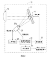
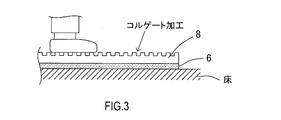
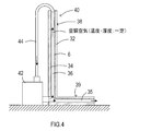
- FIG. 1 It is a schematic block diagram showing the structure of the whole millimeter wave imaging device of embodiment. It is explanatory drawing showing the structure of the imaging device shown in FIG. It is sectional drawing showing the modification of the floor surface of a millimeter wave imaging device. It is explanatory drawing showing the structural example of the shielding board using an electromagnetic wave absorber.
- the imaging apparatus body 10 captures an image of the subject 2 by receiving millimeter-wave band thermal noise radiated from the subject 2.
- the shielding plate 4 is provided on the opposite side of the imaging device main body 10 with the inspection target region interposed therebetween.
- the reflecting plate 14 is swung around the central axis arranged in the horizontal direction, thereby scanning the image formed by the lens antenna 12 in the vertical direction, and thermal noise (millimeter wave) for one horizontal line. ) Are sequentially incident on the line sensor.
- the receiving unit 20 includes a plurality of amplification circuits (not shown) and a plurality of detection circuits (detection diodes, not shown).
- the plurality of amplifier circuits amplify the reception signals from the plurality of antenna elements 20a.
- the plurality of detection circuits respectively detect reception signals from the plurality of antenna elements 20a.
- the detection signal detected by each detection circuit is output from the receiving unit 20 for one line.
- the detection signal is input to the image processing device 30 via the input device 24.
- the image processing device 30 is configured by a microcomputer or the like.
- the image processing device 30 drives the actuator 16 via the driving device 22 to oscillate the reflecting plate 14 and scan the image formed by the lens antenna 12 in the vertical direction, while periodically causing the receiving unit 20 to perform scanning. Output a sync signal. Further, the image processing device 30 sequentially outputs a detection signal for one horizontal line of the imaging image from the receiving unit 20 and sequentially captures the detection signal for one horizontal line, thereby corresponding to the imaging object image. Generated image data is generated.
- the image processing device 30 outputs the generated image data to an external display or storage device via the output device 26. Thereby, a captured image obtained by imaging the inspection target area is displayed on the display, or the image data is stored in the storage device.
- the user of the millimeter-wave imaging device of the present embodiment detects that there is a person who is the subject 2 in the inspection target region by looking at the captured image displayed on the display, or the subject 2 from the display image. It is possible to detect a weapon that is hidden by a certain person.
- the user can confirm the person who is in the inspection target area or the object that the person has. Can do.
- the shielding plate 4 thermal noise in the millimeter wave band that can be received by the receiving unit 20 of the imaging apparatus main body 10 enters the inspection target area from the outside of the inspection target area.
- the shielding plate 4 is made of a metal plate capable of reflecting thermal noise.
- the size of the shielding plate 4 is a size that can cover an imageable range (a region indicated by a one-dot chain line in FIG. 1) in which a subject image can be captured by the receiving unit 20 when viewed from the lens antenna 12.
- the interval (that is, the width of the inspection target area) L1 between the imaging device main body 10 and the shielding plate 4 is set to several meters (for example, about 2.4 m). Then, when the subject 2 is imaged by the imaging apparatus body 10, the user places the person who is the subject 2 near the shielding plate 4 or walks near the shielding plate 4, thereby causing the shielding plate 4 to move from the subject 2. The thermal noise of the millimeter wave band radiated to the side is prevented from being reflected from the shielding plate 4 and entering the imaging apparatus main body 10.
- the shielding plate 4 made of a metal plate capable of reflecting millimeter-wave band thermal noise is provided on the opposite side of the imaging device body 10 across the inspection target region. Is provided.
- the size of the shielding plate 4 is determined by the range that can be received by the receiver 20 in the millimeter-wave band when viewed from the lens antenna 12 (in other words, the imaging apparatus main body 10) (indicated by the one-dot chain line in FIG. 1). Therefore, unnecessary thermal noise incident on the inspection target region from outside the inspection target region can be prevented from entering the receiving unit 20 via the lens antenna 12.
- the imaging apparatus main body 10 can image a person (subject 2) in the inspection target area without being affected by thermal noise incident from outside the inspection target area. Thus, a clear captured image can be obtained.
- the captured image is displayed on the display or stored in the storage device, the user can use a weapon or smuggled goods hidden in the subject 2 based on the displayed or stored captured image. It becomes possible to detect with high accuracy.
- the actuator 16 and its driving device 22 correspond to an example of a scanning unit of the present invention
- the image processing device 30 corresponds to an example of a control unit of the present invention.
- the shielding plate 4 may be formed with a bent portion 4a.
- the bent portion 4a is formed by bending the plate surface of the shielding plate 4 above the shielding plate 4 to the subject 2 side.
- this configuration is a very effective configuration when the shielding plate 4 is installed in a place where the height is limited.
- the said embodiment demonstrated as what uses a metal plate as the shielding board 4, since a shielding board should just be able to shield the thermal noise (millimeter wave) which injected from the outside of the inspection object area, You may comprise using the electromagnetic wave absorber which can absorb noise.
- the shielding plate 4 may be configured using a mesh-like material made of metal. Or you may comprise the shielding board 4 using an electroconductive film.
- the captured image may be disturbed by thermal noise (millimeter wave) reflected from the floor surface. Therefore, as shown in FIG. 3, a sheet material 6 mixed with ferrite or the like as a radio wave absorber is laid on the floor surface on which the subject 2 is placed during imaging, and a reinforcing floor material 8 is provided thereon. You may do it.
- the flooring 8 may be made of a synthetic resin that can transmit thermal noise (millimeter wave). However, it is desirable to form corrugated irregularities on the surface of the flooring 8 by so-called corrugating.
- the reflected wave can be prevented from entering the imaging apparatus main body 10. It also serves to prevent the subject from slipping.
- a radio wave absorber when used for a floor or a shielding plate, it is desirable to keep temperature and humidity constant. This is because the characteristics of the radio wave absorber change depending on temperature and humidity. Therefore, when a floor or a shielding plate is formed using a radio wave absorber, as shown in FIG. 4, a front plate 32 in which a sheet material 6 made of a radio wave absorber is laminated on the back surface and a back plate 34 are used.
- a shielding plate body 40 having a space 36 may be configured, and conditioned air having a constant temperature and a constant humidity may be sent into the internal space 36 from the air conditioner 42.
- the set temperature of the conditioned air at this time is preferably set to a temperature having a large temperature difference from the human body temperature.
- the shielding plate main body 40 includes not only the shielding portion 38 disposed behind the subject but also a floor portion 39 on which the subject is placed, thereby forming an L-shaped cross section as shown in FIG. Has been.
- the air conditioner 42 is placed on the floor on which the shielding plate main body 40 is installed, and sends conditioned air into the shielding plate main body 40 from behind the lower end of the shielding plate main body 40. As a result, the conditioned air is simultaneously fed into the internal space 35 of the floor 39 of the shield plate body 40 and the internal space 36 of the shield 38.
- the shielding plate is constituted by the shielding plate main body 40 having the internal space 36 and the air conditioner 42 that sends conditioned air to the internal space 36, a sheet made of a radio wave absorber provided in the shielding plate main body 40.
- the temperature and humidity of the material 6 can be kept constant. Thereby, the captured image by the imaging device main body 10 can be obtained stably.
- the receiving unit 20 that receives thermal noise is configured by a line sensor in which antenna elements are arranged in a line, and the reflector 14 is swung (scanned) in the vertical direction via the actuator 16.
- the actuator 16 is configured to be able to swing (scannable) the reflecting plate 14 both in the horizontal direction and in the vertical direction
- the receiving unit 20 can be constituted by one antenna element.
- the receiving unit 20 is configured as a two-dimensional sensor (in other words, a planar antenna) in which a plurality of antenna elements are arranged on a plane, the scanning of the subject 2 can be performed without using the reflection plate 14 or the actuator 16 for scanning. An image can be taken.
- a two-dimensional sensor in other words, a planar antenna
- the technique of providing the shielding plate 4 and suppressing the unnecessary thermal noise from entering the thermal noise detecting antenna element as in the above embodiment can be applied to a detection device that detects a person. it can.
Landscapes
- Engineering & Computer Science (AREA)
- Remote Sensing (AREA)
- Radar, Positioning & Navigation (AREA)
- Physics & Mathematics (AREA)
- General Physics & Mathematics (AREA)
- Electromagnetism (AREA)
- Computer Networks & Wireless Communication (AREA)
- Life Sciences & Earth Sciences (AREA)
- General Life Sciences & Earth Sciences (AREA)
- Geophysics (AREA)
- Radar Systems Or Details Thereof (AREA)
- Geophysics And Detection Of Objects (AREA)
Abstract
被写体から放射されるミリ波帯の熱雑音を透過させて、所定の結像位置に当該熱雑音からなる被写体像を結像させるレンズアンテナと、前記レンズアンテナにより結像された被写体像各部の熱雑音を受信する受信アンテナを備え、該受信アンテナによる熱雑音の受信レベルから前記被写体の画像データを生成する画像データ生成手段と、を備えたミリ波撮像装置において、撮像時に前記被写体が位置する被写体配置領域を挟んで、前記レンズアンテナとは反対側に、少なくとも前記レンズアンテナからみて前記アンテナ素子により前記被写体像を撮像可能な撮像可能範囲内で、前記熱雑音の通過を阻止する遮蔽板を設けた。
Description
本国際出願は、2010年4月12日に日本国特許庁に出願された日本国特許出願第2010-091486号に基づく優先権を主張するものであり、日本国特許出願第2010-091486号の全内容を本国際出願に援用する。
本発明は、被写体から放射されるミリ波帯の熱雑音を受信することにより被写体を撮像するミリ波撮像装置に関する。
従来、人体などの被写体から放射されるミリ波帯の熱雑音を受信することによって、被写体を撮像し、その撮像画像から、被写体に隠された武器や密輸品等を検知することが提案されている(例えば、特許文献1、2等参照)。
この提案の装置は、被写体から放射されるミリ波帯の熱雑音を受信することにより被写体を撮像する所謂パッシブ型の撮像装置であることから、被写体にミリ波を照射してその反射波から被写体を撮像するアクティブ型の撮像装置に比べて、装置構成を簡単にすることができる。
しかし、こうしたパッシブ型の撮像装置では、被写体から放射される微弱な熱雑音(ミリ波)を受信し、その微弱な受信信号から被写体の撮像画像を生成することになるため、撮像対象となる被写体が配置される被写体配置領域内に外部から熱雑音が入射すると、その熱雑音の影響を受けて、被写体を正常に撮像することができないことがあった。
本発明は、こうした問題に鑑みなされたものであり、人体などの被写体から放射されるミリ波帯の熱雑音を受信することにより、被写体を撮像するミリ波撮像装置において、被写体の配置領域内に外部から入射した熱雑音の影響を受けることなく、鮮明な被写体像が得られるようにすることを目的とする。
かかる目的を達成するためになされた本願の第1局面の発明は、
被写体から放射されるミリ波帯の熱雑音を透過させて、所定の結像位置に当該熱雑音からなる被写体像を結像させるレンズアンテナと、
前記レンズアンテナにより結像された被写体像各部の熱雑音を受信する受信アンテナを備え、該受信アンテナによる熱雑音の受信レベルから前記被写体の画像データを生成する画像データ生成手段と、
を備えたミリ波撮像装置において、
撮像時に前記被写体が位置する被写体配置領域を挟んで、前記レンズアンテナとは反対側に、少なくとも前記レンズアンテナからみて前記アンテナ素子により前記被写体像を撮像可能な撮像可能範囲内で、前記熱雑音の通過を阻止する遮蔽板を設けたことを特徴とする。
被写体から放射されるミリ波帯の熱雑音を透過させて、所定の結像位置に当該熱雑音からなる被写体像を結像させるレンズアンテナと、
前記レンズアンテナにより結像された被写体像各部の熱雑音を受信する受信アンテナを備え、該受信アンテナによる熱雑音の受信レベルから前記被写体の画像データを生成する画像データ生成手段と、
を備えたミリ波撮像装置において、
撮像時に前記被写体が位置する被写体配置領域を挟んで、前記レンズアンテナとは反対側に、少なくとも前記レンズアンテナからみて前記アンテナ素子により前記被写体像を撮像可能な撮像可能範囲内で、前記熱雑音の通過を阻止する遮蔽板を設けたことを特徴とする。
また、本願の第2局面の発明は、第1局面のミリ波撮像装置において、前記遮蔽板は、前記熱雑音を反射可能な金属からなることを特徴とする。
また、本願の第3局面の発明は、第1局面のミリ波撮像装置において、前記遮蔽板は、前記ミリ波帯の熱雑音を吸収可能な電波吸収体からなることを特徴とする。
また、本願の第3局面の発明は、第1局面のミリ波撮像装置において、前記遮蔽板は、前記ミリ波帯の熱雑音を吸収可能な電波吸収体からなることを特徴とする。
また、本願の第4局面の発明は、第3局面のミリ波撮像装置において、前記遮蔽板を構成する電波吸収体の温度を一定温度にするための温度調整手段を設けたことを特徴とする。
また、本願の第5局面の発明は、第1~第4局面の何れかのミリ波撮像装置において、前記遮蔽板の上方には、板面が前記レンズアンテナ側に向くよう屈曲させた屈曲部が形成されていることを特徴とする。
また、本願の第6局面の発明は、第1~第5局面の何れかのミリ波撮像装置において、前記遮蔽板と前記レンズアンテナとの間の床面の少なくとも一部を、波形形状にしたことを特徴とする。
また、本願の第7局面の発明は、第1~第6局面の何れかのミリ波撮像装置において、
前記画像データ生成手段は、
前記レンズアンテナによる被写体像の結像位置付近に配置され、当該被写体像を形成している熱雑音を前記アンテナ素子に向けて反射する反射板と、
前記反射板を揺動することで、前記被写体像各位置の熱雑音を前記アンテナ素子へ入射させる走査手段と、
前記走査手段を介して前記反射板を揺動しつつ前記アンテナ素子から受信信号を取り込むことで、前記被写体像を表す画像データを生成する制御手段と、
を備えたことを特徴とする。
前記画像データ生成手段は、
前記レンズアンテナによる被写体像の結像位置付近に配置され、当該被写体像を形成している熱雑音を前記アンテナ素子に向けて反射する反射板と、
前記反射板を揺動することで、前記被写体像各位置の熱雑音を前記アンテナ素子へ入射させる走査手段と、
前記走査手段を介して前記反射板を揺動しつつ前記アンテナ素子から受信信号を取り込むことで、前記被写体像を表す画像データを生成する制御手段と、
を備えたことを特徴とする。
第1局面のミリ波撮像装置においては、撮像時に被写体が配置される被写体配置領域を挟んで、レンズアンテナとは反対側に、熱雑音の通過を阻止する遮蔽板が設けられている。
そして、この遮蔽板は、少なくとも、レンズアンテナからみてアンテナ素子により被写体像を撮像可能な撮像可能範囲内で、熱雑音の通過を阻止できる大きさになっていることから、外部から被写体配置領域に入射した熱雑音(ミリ波)が、レンズアンテナを介して、アンテナ素子に入射されるのを抑制できる。
よって、本発明のミリ波撮像装置によれば、遮蔽板により、被写体の後方から撮像可能範囲内に入射する不要な熱雑音を遮断することができるようになり、その不要な熱雑音の影響を受けることなく、被写体を撮像することができるようになる。
このため、本発明のミリ波撮像装置を用いて被写体を撮像すれば、鮮明な被写体像を得ることができ、その撮像画像から被写体に隠された武器や密輸品等を検知する際の検知精度を高めることができる。
ここで、遮蔽板は、不要な熱雑音(ミリ波)を遮蔽することができればよく、第2局面の発明のように、熱雑音を反射可能な金属にて構成してもよく、或いは、第3局面の発明のように、熱雑音を吸収可能な電波吸収体にて構成してもよい。
そして、このうち、電波吸収体は、熱雑音の透過率及び反射率が低く、放射率が高く、しかも、周囲温度が高くなる程、熱雑音(ミリ波)の放射が強くなることから、遮蔽板を電波吸収体にて構成した際には、周囲温度が低く温度変化が少ない条件下で利用する、というように、その利用条件を制限する必要がある。
このため、遮蔽板を電波吸収体にて構成する際には、第4局面の発明のように、遮蔽板を構成する電波吸収体の温度を一定温度にするための温度調整手段を設けることが望ましい。更に言えば、その設定温度は、人体温度と大きな温度差を有した温度に設定するのが望ましい。
これに対し、金属板は、熱雑音の反射率が高く、放射率及び透過率は低く、しかも、これらは温度の影響を受け難いことから、遮蔽板を金属にて構成した際には、利用条件を制限することなく利用することができる。
なお、遮蔽板を金属にて構成する場合、アンテナ素子にて受信されるミリ波帯の熱雑音を遮蔽できればよいので、必ずしも金属板にて構成する必要はない。遮蔽板としては、金属製の網目状のものを利用してもよい。或いは、遮蔽板としては、合成樹脂フィルムに金属箔や金属性のメッシュを貼り付けた導電性フィルムを利用してもよい。
一方、第5局面の発明のように、遮蔽板の上方には、板面がレンズアンテナ側に向くよう屈曲させた屈曲部を形成してもよい。
そしてこのようにした場合、遮蔽板による熱雑音(ミリ波)の遮蔽可能範囲が同じであれば、遮蔽板の高さを低くすることができる。
そしてこのようにした場合、遮蔽板による熱雑音(ミリ波)の遮蔽可能範囲が同じであれば、遮蔽板の高さを低くすることができる。
よって、第5局面の発明は、遮蔽板を高さ制限がある場所に設置する際に極めて有効な発明となる。
ところで、撮像可能範囲に床面が含まれる場合、床面から反射した熱雑音(ミリ波)により、撮像画像が乱れることも考えられる。
ところで、撮像可能範囲に床面が含まれる場合、床面から反射した熱雑音(ミリ波)により、撮像画像が乱れることも考えられる。
このため、このような場合には、第6局面の発明のように、遮蔽板とレンズアンテナとの間の床面の少なくとも一部を、波形形状にすることで、床面の表面における反射を抑制し、熱雑音(ミリ波)の透過性を向上させて、その反射波がレンズアンテナから受信アンテナへ入射するのを抑制するようにしてもよい。
そして、このようにすれば、床面からの反射波の影響を受けることなく、より鮮明な撮像画像を得ることができる。
また、画像データ生成手段は、レンズアンテナにより結像される被写体像の画像領域に、多数のアンテナ素子を2次元配置し、各アンテナ素子からの出力を順次取り込むことで、画像データを生成するようにしてもよい。
また、画像データ生成手段は、レンズアンテナにより結像される被写体像の画像領域に、多数のアンテナ素子を2次元配置し、各アンテナ素子からの出力を順次取り込むことで、画像データを生成するようにしてもよい。
しかし、このためにはミリ波帯の熱雑音を受信可能な多数のアンテナ素子を2次元状に配置した平面アンテナや、各アンテナ素子からの受信信号を各々処理する多数の信号処理回路が必要になるため、ミリ波撮像装置のコストアップを招くことになる。
そこで、画像データ生成手段は、第7局面の発明のように、反射板と、走査手段と、制御手段とから構成し、制御手段が、走査手段を介して反射板を揺動しつつアンテナ素子から受信信号を取り込むことで画像データを生成するようにするとよい。
つまり、このようにすれば、平面アンテナを用いる場合に比べて、アンテナ素子や信号処理回路(後述の検波回路や増幅回路等)の数を減らして、ミリ波撮像装置のコスト低減を図ることができる。
2…被写体、4…遮蔽板、6…シート材(電波吸収体)、8…床材、10…撮像装置本体、12…レンズアンテナ、14…反射板、16…アクチュエータ、20…受信部、20a…アンテナ素子、22…駆動装置、24…入力装置、26…出力装置、30…画像処理装置、32…表板、34…裏板、35,36…内部空間、38…遮蔽部、39…床部、40…遮蔽板本体、42…空調装置、44…循環用パイプ。
以下に本発明の実施形態を図面と共に説明する。
図1は本発明が適用されたミリ波撮像装置全体の構成を表す概略構成図である。
本実施形態のミリ波撮像装置は、空港などで乗客が危険物を隠し持っていないかどうかをチェックするのに使用される。被写体の配置対象領域である検査対象領域に位置する乗客が被写体2とされている。本実施形態のミリ波撮像装置は、撮像装置本体10と、遮蔽板4とから構成されている。
図1は本発明が適用されたミリ波撮像装置全体の構成を表す概略構成図である。
本実施形態のミリ波撮像装置は、空港などで乗客が危険物を隠し持っていないかどうかをチェックするのに使用される。被写体の配置対象領域である検査対象領域に位置する乗客が被写体2とされている。本実施形態のミリ波撮像装置は、撮像装置本体10と、遮蔽板4とから構成されている。
撮像装置本体10は、被写体2から放射されるミリ波帯の熱雑音を受信することにより被写体2の画像を撮像する。
遮蔽板4は、検査対象領域を挟んで撮像装置本体10とは反対側に設けられている。
遮蔽板4は、検査対象領域を挟んで撮像装置本体10とは反対側に設けられている。
ここで、撮像装置本体10には、図2に示すように、レンズアンテナ12と、反射板14と、受信部20と、アクチュエータ16とが備えられている。
レンズアンテナ12は、検査対象領域内に位置する被写体2から放射されたミリ波帯の熱雑音を装置内に取り込み、熱雑音からなる被写体像を結像させる。
レンズアンテナ12は、検査対象領域内に位置する被写体2から放射されたミリ波帯の熱雑音を装置内に取り込み、熱雑音からなる被写体像を結像させる。
反射板14は、レンズアンテナ12による被写体像の結像位置付近に配置されている。
受信部20は、反射板14にて反射されたミリ波帯の熱雑音を受信してその信号レベルを検出する。
受信部20は、反射板14にて反射されたミリ波帯の熱雑音を受信してその信号レベルを検出する。
アクチュエータ16は、反射板14を中心軸周りに双方向に揺動させて、被写体像各位置の熱雑音を受信部20へ入射させる。
受信部20は、ラインセンサにて構成されている。ラインセンサは、ミリ波帯の熱雑音を受信可能な複数のアンテナ素子20aを水平方向に配置して構成される。
受信部20は、ラインセンサにて構成されている。ラインセンサは、ミリ波帯の熱雑音を受信可能な複数のアンテナ素子20aを水平方向に配置して構成される。
反射板14は、水平方向に配置された中心軸周りに揺動されることで、レンズアンテナ12にて結像された画像を垂直方向に走査し、水平方向一ライン分の熱雑音(ミリ波)を順次ラインセンサに入射させる。
また、受信部20には、複数の増幅回路(図示省略)、及び複数の検波回路(検波用のダイオード、図示省略)が内蔵されている。複数の増幅回路は、複数のアンテナ素子20aからの受信信号をそれぞれ増幅する。複数の検波回路は、複数のアンテナ素子20aからの受信信号をそれぞれ検波する。各検波回路により検波された検波信号は一ライン分受信部20から出力される。
そして、この検波信号は、入力装置24を介して、画像処理装置30に入力される。
画像処理装置30は、マイクロコンピュータ等にて構成されている。画像処理装置30は、駆動装置22を介してアクチュエータ16を駆動することにより、反射板14を揺動させて、レンズアンテナ12による結像画像を垂直方向に走査させつつ、受信部20に周期的に同期信号を出力する。さらに、画像処理装置30は、結像画像の水平方向一ライン分の検波信号を順次受信部20から出力させ、その水平方向一ライン分の検波信号を順次取り込むことで、結像体像に対応した画像データを生成する。
画像処理装置30は、マイクロコンピュータ等にて構成されている。画像処理装置30は、駆動装置22を介してアクチュエータ16を駆動することにより、反射板14を揺動させて、レンズアンテナ12による結像画像を垂直方向に走査させつつ、受信部20に周期的に同期信号を出力する。さらに、画像処理装置30は、結像画像の水平方向一ライン分の検波信号を順次受信部20から出力させ、その水平方向一ライン分の検波信号を順次取り込むことで、結像体像に対応した画像データを生成する。
そして、画像処理装置30は、その生成した画像データを、出力装置26を介して外部のディスプレイや記憶装置へ出力する。これにより、検査対象領域を撮像した撮像画像がディスプレイへ表示されるか、或いは、その画像データが記憶装置に記憶される。
従って、本実施形態のミリ波撮像装置の使用者は、ディスプレイに表示された撮像画像を見ることで、検査対象領域に被写体2となる人が居ることを検知したり、その表示画像から被写体2である人が隠し持っている凶器を検知したりすることができる。
また、記憶装置に記憶された画像データにてディスプレイに撮像画像を表示させることで、使用者は、検査対象領域に居た人物を確認するとか、その人物が持っている物体を確認するといったことができる。
遮蔽板4は、検査対象領域の外部から検査対象領域内に、撮像装置本体10の受信部20にて受信可能なミリ波帯の熱雑音が侵入し、その侵入した熱雑音が撮像装置本体10内に入射するのを抑制するためのものであり、本実施形態では、遮蔽板4は熱雑音を反射可能な金属板にて構成されている。
遮蔽板4の大きさは、レンズアンテナ12からみて、受信部20により被写体像を撮像可能な撮像可能範囲(図1に一点鎖線で示す領域)をカバーすることのできる大きさになっている。
なお、本実施形態のミリ波撮像装置において、撮像装置本体10と遮蔽板4との間隔(つまり検査対象領域の幅)L1は、数メートル(例えば約2.4m)に設定されている。
そして、撮像装置本体10にて被写体2を撮像する際、使用者は、被写体2である人を遮蔽板4付近に立たせるか、遮蔽板4近傍を歩かせることにより、被写体2から遮蔽板4側に放射されたミリ波帯の熱雑音が遮蔽板4から反射されて撮像装置本体10に入射するのを抑制する。
そして、撮像装置本体10にて被写体2を撮像する際、使用者は、被写体2である人を遮蔽板4付近に立たせるか、遮蔽板4近傍を歩かせることにより、被写体2から遮蔽板4側に放射されたミリ波帯の熱雑音が遮蔽板4から反射されて撮像装置本体10に入射するのを抑制する。
このように、本実施形態のミリ波撮像装置によれば、検査対象領域を挟んで撮像装置本体10とは反対側に、ミリ波帯の熱雑音を反射可能な金属板からなる遮蔽板4が設けられている。
そして、この遮蔽板4の大きさは、レンズアンテナ12(換言すれば撮像装置本体10)からみて、受信部20によりミリ波帯の熱雑音を受信可能な撮像可能範囲(図1に一点鎖線で示す領域)をカバーできる大きさになっているので、検査対象領域の外から検査対象領域に入射した不要な熱雑音が、レンズアンテナ12を介して受信部20に入射するのを抑制できる。
よって、本実施形態によれば、撮像装置本体10において、検査対象領域外から入射した熱雑音の影響を受けることなく、検査対象領域内に居る人(被写体2)を撮像することができるようになり、鮮明な撮像画像を得ることができる。
そして、その撮像画像は、ディスプレイに表示されるか、若しくは記憶装置に記憶されることから、使用者は、表示若しくは記憶された撮像画像に基づき、被写体2に隠された武器や密輸品等を精度良く検知することができるようになる。
ここで、文言の対応関係を説明する。ただし、次の記載は、各手段の具体的構成を限定する趣旨のものではない。本実施形態においては、アクチュエータ16及びその駆動装置22が、本発明の走査手段の一例に相当し、画像処理装置30が本発明の制御手段の一例に相当する。
以上、本発明の一実施形態について説明したが、本発明は上記実施形態に限定されるものではなく、本発明の要旨を逸脱しない範囲内にて種々の態様をとることができる。
例えば、図1に点線及び符号4aで示すように、遮蔽板4には、屈曲部4aを形成してもよい。屈曲部4aは、遮蔽板4の上方でその遮蔽板4の板面を被写体2側に屈曲させて形成したものである。
例えば、図1に点線及び符号4aで示すように、遮蔽板4には、屈曲部4aを形成してもよい。屈曲部4aは、遮蔽板4の上方でその遮蔽板4の板面を被写体2側に屈曲させて形成したものである。
そしてこのようにした場合、熱雑音(ミリ波)の遮蔽可能範囲が同じであれば、遮蔽板4の高さを低くすることができる(図1では高さをH1だけ低くできる)。
よって、この構成は、遮蔽板4を高さ制限がある場所に設置する際に極めて有効な構成となる。
よって、この構成は、遮蔽板4を高さ制限がある場所に設置する際に極めて有効な構成となる。
また、上記実施形態では、遮蔽板4として、金属板を用いるものとして説明したが、遮蔽板は、検査対象領域外から入射した熱雑音(ミリ波)を遮蔽することができればよいことから、熱雑音を吸収可能な電波吸収体を用いて構成してもよい。例えば、遮蔽板4は、金属からなる網目状のものを用いて構成してもよい。或いは、遮蔽板4は、導電性フィルムを用いて構成してもよい。
また、撮像装置本体10による撮像可能範囲に床面が含まれる場合、床面から反射した熱雑音(ミリ波)により、撮像画像が乱れることも考えられる。
そこで、図3に示すように、撮像時に被写体2が載る床面には、電波吸収体であるフェライト等を混入させたシート材6を敷設し、その上に、補強用の床材8を設けるようにしてもよい。
そこで、図3に示すように、撮像時に被写体2が載る床面には、電波吸収体であるフェライト等を混入させたシート材6を敷設し、その上に、補強用の床材8を設けるようにしてもよい。
床材8は、熱雑音(ミリ波)を透過可能な合成樹脂にて構成してもよい。ただし、その床材8の表面には、所謂コルゲート加工によって波形形状の凹凸を形成することが望ましい。
このようにすれば、床材8表面からの熱雑音(ミリ波)の反射が抑制されるため、その反射波が撮像装置本体10に入射することを抑制できる。また、被験者の滑り止めにもなる。
好ましくは、床や遮蔽板に電波吸収体を用いる場合、温度や湿度を一定に保持することが望ましい。電波吸収体は、温度や湿度によって特性が変化するためである。
そこで、電波吸収体を用いて床や遮蔽板を形成する際には、図4に示すように、裏面に電波吸収体からなるシート材6を積層した表板32と、裏板34とで、内部空間36を有する遮蔽板本体40を構成し、その内部空間36に、空調装置42から一定温度・一定湿度の空調空気を送り込むようにするとよい。
そこで、電波吸収体を用いて床や遮蔽板を形成する際には、図4に示すように、裏面に電波吸収体からなるシート材6を積層した表板32と、裏板34とで、内部空間36を有する遮蔽板本体40を構成し、その内部空間36に、空調装置42から一定温度・一定湿度の空調空気を送り込むようにするとよい。
そして、このときの空調空気の設定温度は、人体温度と大きな温度差を有するような温度に設定するのがよい。
ここで、遮蔽板本体40は、被写体の後方に配置される遮蔽部38だけでなく、被写体が載るための床部39も備えており、これにより図4に示すように断面L字型に形成されている。空調装置42は、遮蔽板本体40が設置される床の上に置かれ、遮蔽板本体40の下端後方からその遮蔽板本体40の内部に空調空気を送り込む。これにより、遮蔽板本体40の床部39の内部空間35と遮蔽部38の内部空間36とに同時に空調空気が送り込まれる。
ここで、遮蔽板本体40は、被写体の後方に配置される遮蔽部38だけでなく、被写体が載るための床部39も備えており、これにより図4に示すように断面L字型に形成されている。空調装置42は、遮蔽板本体40が設置される床の上に置かれ、遮蔽板本体40の下端後方からその遮蔽板本体40の内部に空調空気を送り込む。これにより、遮蔽板本体40の床部39の内部空間35と遮蔽部38の内部空間36とに同時に空調空気が送り込まれる。
そして、遮蔽板本体40の遮蔽部38側に送り込まれた空調空気は、遮蔽部38の上端側から循環用パイプ44を介して、空調装置42に戻される。戻された空調空気は、空調装置42にて温度、湿度が再調整された後、再度、遮蔽板本体40に送られる。
このように、遮蔽板を、内部空間36を有する遮蔽板本体40とその内部空間36に空調空気を送り込む空調装置42とで構成すれば、遮蔽板本体40に設けられた電波吸収体からなるシート材6の温度・湿度を一定に保つことができる。これにより、撮像装置本体10による撮像画像が安定して得られるようになる。
なお、遮蔽部38及び床部39の表板32には、ミリ波の透過率の高いものを使用するのが望ましい。
また、床部39の表板32の表面には、図3に示したように、所謂コルゲート加工によって波形形状の凹凸を形成することが望ましい。
また、床部39の表板32の表面には、図3に示したように、所謂コルゲート加工によって波形形状の凹凸を形成することが望ましい。
また、上記実施形態においては、熱雑音を受信する受信部20を、アンテナ素子を一列に配置してなるラインセンサにて構成し、アクチュエータ16を介して反射板14を垂直方向に揺動(走査)することで、被写体2の画像を撮像するものとして説明したが、例えば、アクチュエータ16を、反射板14を水平方向にも垂直方向にも揺動可能(走査可能)に構成すれば、受信部20を一つのアンテナ素子にて構成することができる。
また例えば、受信部20を、複数のアンテナ素子を平面上に配置した2次元センサ(換言すれば平面アンテナ)として構成すれば、走査用の反射板14やアクチュエータ16を用いることなく、被写体2の画像を撮像することができる。
一方、上記実施形態のように、遮蔽板4を設けて、熱雑音検出用のアンテナ素子に不要な熱雑音が入射されるのを抑制する技術は、人を検知する検知装置に適用することもできる。
Claims (7)
- 被写体から放射されるミリ波帯の熱雑音を透過させて、所定の結像位置に当該熱雑音からなる被写体像を結像させるレンズアンテナと、
前記レンズアンテナにより結像された被写体像各部の熱雑音を受信する受信アンテナを備え、該受信アンテナによる熱雑音の受信レベルから前記被写体の画像データを生成する画像データ生成手段と、
を備えたミリ波撮像装置において、
撮像時に前記被写体が位置する被写体配置領域を挟んで、前記レンズアンテナとは反対側に、少なくとも前記レンズアンテナからみて前記アンテナ素子により前記被写体像を撮像可能な撮像可能範囲内で、前記熱雑音の通過を阻止する遮蔽板を設けたことを特徴とするミリ波撮像装置。 - 前記遮蔽板は、前記熱雑音を反射可能な金属からなることを特徴とする請求項1に記載のミリ波撮像装置。
- 前記遮蔽板は、前記ミリ波帯の熱雑音を吸収可能な電波吸収体からなることを特徴とする請求項1に記載のミリ波撮像装置。
- 前記遮蔽板を構成する電波吸収体の温度を一定温度にするための温度調整手段を設けたことを特徴とする請求項3に記載のミリ波撮像装置。
- 前記遮蔽板の上方には、板面が前記レンズアンテナ側に向くよう屈曲させた屈曲部が形成されていることを特徴とする請求項1~請求項4の何れか1項に記載のミリ波撮像装置。
- 前記遮蔽板と前記レンズアンテナとの間の床面の少なくとも一部を、波形形状にしたことを特徴とする請求項1~請求項5の何れか1項に記載のミリ波撮像装置。
- 前記画像データ生成手段は、
前記レンズアンテナによる被写体像の結像位置付近に配置され、当該被写体像を形成している熱雑音を前記アンテナ素子に向けて反射する反射板と、
前記反射板を揺動することで、前記被写体像各位置の熱雑音を前記アンテナ素子へ入射させる走査手段と、
前記走査手段を介して前記反射板を揺動しつつ前記アンテナ素子から受信信号を取り込むことで、前記被写体像を表す画像データを生成する制御手段と、
を備えたことを特徴とする請求項1~請求項6の何れか1項に記載のミリ波撮像装置。
Priority Applications (2)
| Application Number | Priority Date | Filing Date | Title |
|---|---|---|---|
| SG2012075958A SG184561A1 (en) | 2010-04-12 | 2011-04-12 | Millimeter-wave image capturing device |
| CN201180018785XA CN102918427A (zh) | 2010-04-12 | 2011-04-12 | 毫米波成像设备 |
Applications Claiming Priority (2)
| Application Number | Priority Date | Filing Date | Title |
|---|---|---|---|
| JP2010091486 | 2010-04-12 | ||
| JP2010-091486 | 2010-04-12 |
Publications (1)
| Publication Number | Publication Date |
|---|---|
| WO2011129342A1 true WO2011129342A1 (ja) | 2011-10-20 |
Family
ID=44798713
Family Applications (1)
| Application Number | Title | Priority Date | Filing Date |
|---|---|---|---|
| PCT/JP2011/059107 Ceased WO2011129342A1 (ja) | 2010-04-12 | 2011-04-12 | ミリ波撮像装置 |
Country Status (4)
| Country | Link |
|---|---|
| JP (1) | JP2011237417A (ja) |
| CN (1) | CN102918427A (ja) |
| SG (1) | SG184561A1 (ja) |
| WO (1) | WO2011129342A1 (ja) |
Cited By (5)
| Publication number | Priority date | Publication date | Assignee | Title |
|---|---|---|---|---|
| JP2013126235A (ja) * | 2011-12-16 | 2013-06-24 | Chuo Electronics Co Ltd | 出力補正装置、方法、プログラム、および撮像システム |
| CN105510911A (zh) * | 2015-12-25 | 2016-04-20 | 深圳市太赫兹科技创新研究院 | 基于线性调频的多人人体安检设备及方法 |
| CN105510912A (zh) * | 2015-12-25 | 2016-04-20 | 深圳市太赫兹科技创新研究院 | 基于毫米波全息三维成像的人体安检系统及方法 |
| CN105607056A (zh) * | 2015-12-28 | 2016-05-25 | 深圳市太赫兹科技创新研究院 | 人体安检系统和方法 |
| WO2017113465A1 (zh) * | 2015-12-28 | 2017-07-06 | 深圳市太赫兹科技创新研究院 | 毫米波全息三维成像检测系统和方法 |
Families Citing this family (2)
| Publication number | Priority date | Publication date | Assignee | Title |
|---|---|---|---|---|
| JP2013246138A (ja) * | 2012-05-29 | 2013-12-09 | Maspro Denkoh Corp | 携帯型マイクロ波測定装置 |
| CN104375144A (zh) | 2013-08-15 | 2015-02-25 | 同方威视技术股份有限公司 | 毫米波三维全息扫描成像设备及人体或物品检查方法 |
Citations (1)
| Publication number | Priority date | Publication date | Assignee | Title |
|---|---|---|---|---|
| US20050110672A1 (en) * | 2003-10-10 | 2005-05-26 | L-3 Communications Security And Detection Systems, Inc. | Mmw contraband screening system |
Family Cites Families (6)
| Publication number | Priority date | Publication date | Assignee | Title |
|---|---|---|---|---|
| JPS63281500A (ja) * | 1987-05-13 | 1988-11-17 | Seiko Instr & Electronics Ltd | 電磁波吸収プレ−ト |
| JP2000050115A (ja) * | 1998-07-29 | 2000-02-18 | Konica Corp | 撮影方法及び撮影装置 |
| US7194236B2 (en) * | 2001-09-28 | 2007-03-20 | Trex Enterprises Corp. | Millimeter wave imaging system |
| JP2004177198A (ja) * | 2002-11-26 | 2004-06-24 | Hitachi Ltd | 電磁波画像処理装置 |
| CA2539040A1 (en) * | 2003-09-15 | 2005-03-24 | The Council For The Central Laboratory Of The Research Councils | Millimetre and sub-millimetre imaging device |
| JP2008241352A (ja) * | 2007-03-26 | 2008-10-09 | Maspro Denkoh Corp | ミリ波撮像装置及び撮像画像表示装置 |
-
2011
- 2011-04-12 JP JP2011088368A patent/JP2011237417A/ja active Pending
- 2011-04-12 CN CN201180018785XA patent/CN102918427A/zh active Pending
- 2011-04-12 WO PCT/JP2011/059107 patent/WO2011129342A1/ja not_active Ceased
- 2011-04-12 SG SG2012075958A patent/SG184561A1/en unknown
Patent Citations (1)
| Publication number | Priority date | Publication date | Assignee | Title |
|---|---|---|---|---|
| US20050110672A1 (en) * | 2003-10-10 | 2005-05-26 | L-3 Communications Security And Detection Systems, Inc. | Mmw contraband screening system |
Non-Patent Citations (1)
| Title |
|---|
| JUN NAKATA ET AL.: "Real-time Calibration Method of MM-wave Image Using Upper-edge of Back-ground Temperature", 2009 NEN IEICE ELECTRONICS SOCIETY TAIKAI KOEN RONBUNSHU 1, 1 September 2009 (2009-09-01), pages 143, XP008148093 * |
Cited By (8)
| Publication number | Priority date | Publication date | Assignee | Title |
|---|---|---|---|---|
| JP2013126235A (ja) * | 2011-12-16 | 2013-06-24 | Chuo Electronics Co Ltd | 出力補正装置、方法、プログラム、および撮像システム |
| CN105510911A (zh) * | 2015-12-25 | 2016-04-20 | 深圳市太赫兹科技创新研究院 | 基于线性调频的多人人体安检设备及方法 |
| CN105510912A (zh) * | 2015-12-25 | 2016-04-20 | 深圳市太赫兹科技创新研究院 | 基于毫米波全息三维成像的人体安检系统及方法 |
| WO2017107284A1 (zh) * | 2015-12-25 | 2017-06-29 | 深圳市太赫兹科技创新研究院 | 基于毫米波全息三维成像的人体安检系统及方法 |
| CN110632593A (zh) * | 2015-12-25 | 2019-12-31 | 华讯方舟科技有限公司 | 基于毫米波全息三维成像的人体安检系统及方法 |
| CN105607056A (zh) * | 2015-12-28 | 2016-05-25 | 深圳市太赫兹科技创新研究院 | 人体安检系统和方法 |
| WO2017113465A1 (zh) * | 2015-12-28 | 2017-07-06 | 深圳市太赫兹科技创新研究院 | 毫米波全息三维成像检测系统和方法 |
| US11313963B2 (en) | 2015-12-28 | 2022-04-26 | Shenzhen Cct Thz Technology Co., Ltd. | Millimeter wave holographic three-dimensional imaging detection system and method |
Also Published As
| Publication number | Publication date |
|---|---|
| SG184561A1 (en) | 2012-11-29 |
| JP2011237417A (ja) | 2011-11-24 |
| CN102918427A (zh) | 2013-02-06 |
Similar Documents
| Publication | Publication Date | Title |
|---|---|---|
| JP2011237417A (ja) | ミリ波撮像装置 | |
| US8928608B2 (en) | Touch screen, touch system and method for positioning a touch object in touch system | |
| RU2510036C2 (ru) | Адаптивная система обнаружения | |
| JP6643203B2 (ja) | レーダ装置 | |
| CN102253392B (zh) | 飞行时间摄像机单元和光学监视系统 | |
| KR102494086B1 (ko) | 지문 검출 장치, 방법 및 전자 장치 | |
| JP5626723B2 (ja) | ミリ波撮像装置 | |
| US20170222311A1 (en) | Vehicle sensing system with radar antenna radome | |
| EP3550287A1 (en) | Image acquisition device, image acquisition method using same, and irradiation device | |
| CN108303679A (zh) | 罩部件以及传感器组件 | |
| JP2014051284A (ja) | 一体型レーダー−カメラセンサ | |
| JP6549951B2 (ja) | レーダ装置を取り付けた構造体、レーダ装置の取り付け方法、および、ブラケット | |
| JP6317657B2 (ja) | レーダーセンサモジュール | |
| JP2017044527A (ja) | レーダ装置 | |
| US11022677B2 (en) | Device for calibrating an imaging system and associated calibrating method | |
| US12161493B2 (en) | Radiation imaging apparatus and radiation imaging system | |
| US20210281327A1 (en) | Terahertz wave camera system, entry/exit management apparatus, and method for controlling terahertz wave camera system | |
| JP5464644B2 (ja) | ミリ波撮像装置およびプログラム | |
| US20130187892A1 (en) | Optical touch device | |
| CN113514417A (zh) | 一种太赫兹成像系统中探测器自身干扰的抑制方法和装置 | |
| CN216082475U (zh) | 一种太赫兹成像系统中探测器自身干扰的抑制装置 | |
| CN102713670A (zh) | 毫米波成像设备、毫米波成像系统和程序 | |
| KR20150061547A (ko) | 레이저 레이더 장치 및 그것의 동작 방법 | |
| KR101967499B1 (ko) | 방사선 검출 장치 및 방사선 촬상 시스템 | |
| JP5619555B2 (ja) | アンテナ装置 |
Legal Events
| Date | Code | Title | Description |
|---|---|---|---|
| WWE | Wipo information: entry into national phase |
Ref document number: 201180018785.X Country of ref document: CN |
|
| 121 | Ep: the epo has been informed by wipo that ep was designated in this application |
Ref document number: 11768863 Country of ref document: EP Kind code of ref document: A1 |
|
| NENP | Non-entry into the national phase |
Ref country code: DE |
|
| 122 | Ep: pct application non-entry in european phase |
Ref document number: 11768863 Country of ref document: EP Kind code of ref document: A1 |