WO2011129334A1 - 圧着端子の導体圧着部の検査方法 - Google Patents
圧着端子の導体圧着部の検査方法 Download PDFInfo
- Publication number
- WO2011129334A1 WO2011129334A1 PCT/JP2011/059095 JP2011059095W WO2011129334A1 WO 2011129334 A1 WO2011129334 A1 WO 2011129334A1 JP 2011059095 W JP2011059095 W JP 2011059095W WO 2011129334 A1 WO2011129334 A1 WO 2011129334A1
- Authority
- WO
- WIPO (PCT)
- Prior art keywords
- conductor
- bottom plate
- terminal
- crimping portion
- conductor crimping
- Prior art date
- Legal status (The legal status is an assumption and is not a legal conclusion. Google has not performed a legal analysis and makes no representation as to the accuracy of the status listed.)
- Ceased
Links
Images


Classifications
-
- H—ELECTRICITY
- H01—ELECTRIC ELEMENTS
- H01R—ELECTRICALLY-CONDUCTIVE CONNECTIONS; STRUCTURAL ASSOCIATIONS OF A PLURALITY OF MUTUALLY-INSULATED ELECTRICAL CONNECTING ELEMENTS; COUPLING DEVICES; CURRENT COLLECTORS
- H01R4/00—Electrically-conductive connections between two or more conductive members in direct contact, i.e. touching one another; Means for effecting or maintaining such contact; Electrically-conductive connections having two or more spaced connecting locations for conductors and using contact members penetrating insulation
- H01R4/10—Electrically-conductive connections between two or more conductive members in direct contact, i.e. touching one another; Means for effecting or maintaining such contact; Electrically-conductive connections having two or more spaced connecting locations for conductors and using contact members penetrating insulation effected solely by twisting, wrapping, bending, crimping, or other permanent deformation
- H01R4/18—Electrically-conductive connections between two or more conductive members in direct contact, i.e. touching one another; Means for effecting or maintaining such contact; Electrically-conductive connections having two or more spaced connecting locations for conductors and using contact members penetrating insulation effected solely by twisting, wrapping, bending, crimping, or other permanent deformation by crimping
- H01R4/188—Electrically-conductive connections between two or more conductive members in direct contact, i.e. touching one another; Means for effecting or maintaining such contact; Electrically-conductive connections having two or more spaced connecting locations for conductors and using contact members penetrating insulation effected solely by twisting, wrapping, bending, crimping, or other permanent deformation by crimping having an uneven wire-receiving surface to improve the contact
-
- G—PHYSICS
- G01—MEASURING; TESTING
- G01B—MEASURING LENGTH, THICKNESS OR SIMILAR LINEAR DIMENSIONS; MEASURING ANGLES; MEASURING AREAS; MEASURING IRREGULARITIES OF SURFACES OR CONTOURS
- G01B11/00—Measuring arrangements characterised by the use of optical techniques
- G01B11/02—Measuring arrangements characterised by the use of optical techniques for measuring length, width or thickness
-
- H—ELECTRICITY
- H01—ELECTRIC ELEMENTS
- H01R—ELECTRICALLY-CONDUCTIVE CONNECTIONS; STRUCTURAL ASSOCIATIONS OF A PLURALITY OF MUTUALLY-INSULATED ELECTRICAL CONNECTING ELEMENTS; COUPLING DEVICES; CURRENT COLLECTORS
- H01R43/00—Apparatus or processes specially adapted for manufacturing, assembling, maintaining, or repairing of line connectors or current collectors or for joining electric conductors
- H01R43/04—Apparatus or processes specially adapted for manufacturing, assembling, maintaining, or repairing of line connectors or current collectors or for joining electric conductors for forming connections by deformation, e.g. crimping tool
- H01R43/048—Crimping apparatus or processes
- H01R43/0488—Crimping apparatus or processes with crimp height adjusting means
Definitions
- the present invention relates to a method for inspecting a conductor crimping part of an open barrel type crimping terminal used for, for example, an electrical system of an automobile.
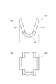
- FIG. 4A and 4B show a cross section and a plane of a conductor crimping portion 112 of a general crimp terminal
- FIG. 5 shows a cross section of the conductor crimping portion 112 crimped to a conductor W of an electric wire.
- the conductor crimping portion 112 of the crimp terminal is rounded inward so as to enclose the bottom plate 121 and the conductor W of the electric wire extending upward from the left and right side edges of the bottom plate 121 and arranged on the inner surface of the bottom plate 121.
- the bottom plate 121 is formed in a substantially curved U-shape by a pair of conductor caulking pieces 122 and 122 that are caulked so that each tip bites into the conductor W.
- a concave portion that is present in a groove shape or a dot shape called serration 123 is formed on the inner surface of the conductor crimp portion 112, and the conductor and the terminal when crimped to the conductor.
- serration 123 is formed on the inner surface of the conductor crimp portion 112, and the conductor and the terminal when crimped to the conductor.
- the conductor crimping part 112 when the conductor crimping part 112 is crimped to the conductor W of the electric wire, the dimensional accuracy (depth or width) of the serration 123 formed on the inner surface of the conductor crimping part 112 has a great influence on the subsequent crimping performance. I know that. Therefore, at present, an appropriate number of products manufactured on the terminal manufacturing line are sampled and inspected offline using a measuring instrument such as a laser displacement meter.
- the present invention makes it possible to easily grasp the dimensions of serrations and the dimensions of the portions where serrations are arranged in-line with respect to the total number in the crimp terminal manufacturing line, and ensure strict guarantees. It aims at providing the inspection method of the conductor crimping part of the crimp terminal which can be performed with respect to all.
- the first invention has a conductor crimping portion that is crimped and connected to a conductor of an electric wire, and the conductor crimping portion includes a bottom plate on which the conductor is placed on an inner surface, and left and right sides of the bottom plate.
- the bottom plate of the conductor crimping portion is formed into a flat plate shape having a predetermined width, and the conductor crimping portion is pressed into a substantially U-shaped cross section, and the serration is placed within the inner surface width of the flat plate-like bottom plate.
- Manufactures arranged crimp terminals, while the terminals A non-contact type dimension measuring device is installed at the final stage of the manufacturing line, and the bottom plate is measured by measuring the upper surface of the flat plate of the conductor crimping portion of the crimping terminal conveyed by the dimension measuring device.
- the data of at least one of the inner surface width, the serration width, and the serration depth is obtained as an inspection result.
- the laser beam is directly above the upper surface of the bottom plate of the conductor crimping portion which is the target location.
- the dimensions of the target portion are measured.
- the bottom plate of the conductor crimping portion is processed into a flat plate shape having a predetermined width, the posture of the terminal at the time of inspection can be stabilized, and the upper surface is also held as a flat surface. Therefore, it is possible to reduce inspection errors when measuring dimensions from directly above.
- a non-contact type dimension measuring device is installed at the final stage of the terminal production line, and the inner surface width of the bottom plate is measured by measuring the upper surface of the bottom surface of the conductor crimping portion of the crimp terminal being conveyed by the dimension measuring device.
- the data of at least one of the serration width and serration depth is obtained as an inspection result, it is possible to inspect all the items online, and to guarantee the accuracy of all the crimp terminals. Product reliability can be improved.
- the shape of the crimping terminal even if the bottom plate of the conductor crimping part is formed into a flat plate shape, it can be handled only by changing the terminal bending piece with respect to the conventional shape. Can be changed.
- the laser displacement meter since the laser displacement meter is used as the non-contact type dimension measuring device, it can be easily implemented by adding simple equipment without causing a significant increase in cost.
- FIG.1 (a) is sectional drawing seen from the front
- FIG.1 (b) is a top view. It is the top view which looked at the implementation condition of the inspection method of the embodiment of the present invention from the top. It is explanatory drawing about the detail of the test
- Fig.4 (a) is sectional drawing seen from the front
- FIG.4 (b) is a top view. It is sectional drawing which shows the state after crimping to the conductor of the conductor crimping
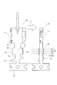
- FIG. 1A and 1B are configuration diagrams of a conductor crimping portion of a crimp terminal to be inspected in the inspection method of the embodiment.
- FIG. 1A is a cross-sectional view seen from the front, and FIG. ) Is a plan view.
- FIG. 2 is a plan view of the state of implementation of the inspection method according to the embodiment, and
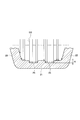
- FIG. 3 is an explanatory diagram illustrating details of the inspection method according to the embodiment.
- the crimping terminal 10 to be inspected here has a conductor crimping portion 12 that is crimped and connected to a conductor of an electric wire (see FIG. 5), as shown in FIGS. 1 (a) and 1 (b).
- the conductor crimping portion 12 is rounded inward so as to enclose the bottom plate 21 on which the conductor is placed on the inner surface, and the conductor that extends on both the left and right sides of the bottom plate 21 and is placed on the inner surface of the bottom plate 21.
- a pair of left and right conductor crimping pieces 22, 22 that are crimped so that each tip bites into the conductor, and is formed into a substantially U-shaped cross section. This is a crimp terminal provided with serrations 25 for increasing connectivity.
- the crimp terminal 10 is completed as a final product by being sequentially pressed in a series of terminal manufacturing lines. Now, in FIG. 2, the press intermediate product sequentially flows in the direction of arrow F from the left side to the right side of the figure.
- the left crimping terminal 10 is a terminal at a stage where it is developed in a flat shape, and the right terminal is a finished product. The terminal of the finished product is inspected at the final stage and sent as a product to the next caulking process.
- the crimp terminal 10 is manufactured by being pressed in a chain on a single metal plate in a state where one side edge is connected by the carrier 17. In the intermediate process part until it finally becomes the crimp terminal 10, it is formed in a flat unfolded terminal shape by press punching one metal plate.
- the crimp terminal 10 includes an electrical connection portion 11 for a mating terminal or the like on the front end side of the connecting wire extending direction (hereinafter, this direction is referred to as “front-rear direction” and the direction orthogonal thereto is referred to as “left-right direction”).
- a conductor crimping portion 12 that is crimped to the exposed conductor at the tip of the electric wire and a covering crimping portion 13 that is crimped to a portion having a coating of the electric wire are provided.
- the conductor crimping portion 12 and the covering crimping portion 13 are continuously formed as having a common bottom plate. In FIG.
- a portion indicated by reference numeral 14 is a connecting portion between the electrical connecting portion 11 and the conductor crimping portion 12
- a portion indicated by reference numeral 15 is a connecting portion between the conductor crimping portion 12 and the covering crimping portion 13.
- the bottom plate 21 of the conductor crimping portion 12 is formed in a flat plate shape having a predetermined width, and the conductor crimping portion 12 has a substantially cross-sectional shape.
- a crimp terminal in which a plurality of circular recess-shaped serrations 25 are arranged within the inner surface width S of the flat bottom plate 21 is manufactured while being pressed into a letter shape.
- a laser displacement meter P is installed at the final stage of the terminal production line as a non-contact type dimension measuring device, and the conductor of the crimp terminal 10 conveyed by the laser displacement meter P.
- a laser beam SB By scanning the upper surface of the flat bottom plate 21 of the crimping portion 12 with a laser beam SB as shown in FIG. 3, the inner surface width of the bottom plate 21 as shown in FIGS. 1 (a) and 1 (b).
- Data of at least one of S, the width T of the serration 25, and the depth H of the serration 25 is acquired as an inspection result.
- the laser displacement meter P used as a non-contact type dimension measuring device irradiates and scans a laser beam on the upper surface of the bottom plate 21 of the conductor crimping portion 12 that is a target location from above.
- the dimensions of the target location can be measured, and as shown in FIG. 2, a plurality of locations can be measured simultaneously by arranging a plurality of them in the terminal longitudinal direction or setting a plurality of scan lines P1 to P3. Can be measured.
- the laser beam scanning may be performed by the laser displacement meter P itself or may be performed by feeding the crimp terminal 10.
- the bottom plate 21 of the conductor crimping portion 12 is processed into a flat plate shape having a predetermined width, the posture of the terminal 10 at the time of inspection can be stabilized and the top surface is also flat. Since it can hold
- a laser displacement meter P as a non-contact type dimension measuring device is installed at the final stage of the terminal production line, and the upper surface of the bottom plate 21 of the conductor crimping portion 12 of the crimping terminal 10 conveyed by the laser displacement meter P.
- the shape of the crimping terminal 10 even if the bottom plate 21 of the conductor crimping part 12 is formed into a flat plate shape, it is possible to cope with the conventional shape only by changing the terminal bending piece. Production can be changed at low cost.
- the laser displacement meter P when used as a non-contact type dimension measuring device as in the present embodiment, it can be easily implemented by adding simple equipment without causing a significant increase in cost.
- the case where the circular concave serrations 25 are scattered within the inner surface width of the upper surface of the bottom plate 21 is not particularly limited.
- the bottom plate of the conductor crimping portion is processed into a flat plate having a predetermined width, the posture of the terminal at the time of inspection can be stabilized, and the upper surface is also held as a flat surface. Inspection errors when measuring dimensions from directly above can be reduced.
- a non-contact type dimension measuring device is installed at the final stage of the terminal production line, and the inner surface width of the bottom plate is measured by measuring the upper surface of the bottom surface of the conductor crimping portion of the crimp terminal being conveyed by the dimension measuring device. Since the data of at least one of the serration width and serration depth is obtained as an inspection result, it is possible to inspect all the items online, and to guarantee the accuracy of all the crimp terminals.
Landscapes
- Engineering & Computer Science (AREA)
- Manufacturing & Machinery (AREA)
- Physics & Mathematics (AREA)
- General Physics & Mathematics (AREA)
- Manufacturing Of Electrical Connectors (AREA)
- Connections Effected By Soldering, Adhesion, Or Permanent Deformation (AREA)
- Length Measuring Devices By Optical Means (AREA)
Abstract
Description
12 導体圧着部
21 底板
22 導体加締片
25 セレーション
W 導体
P レーザ変位計(寸法計測装置)
SB レーザビーム
S 底板の内面幅
T セレーションの幅
H セレーションの深さ
Claims (2)
- 電線の導体に圧着して接続される導体圧着部を有し、該導体圧着部が、前記導体が内面に載る底板と、該底板の左右両側に延設されて該底板の内面上に載せられた前記導体を包むように内側に向けて丸められ、各先端が前記導体に食い込むように加締められる左右一対の導体加締片とで断面略U字状に形成されると共に、前記導体圧着部の内面に、前記導体と端子との接続性を増すためのセレーションが設けられた圧着端子の導体圧着部の検査方法であって、
端子製造ライン上にて、前記導体圧着部の底板を所定幅を有する平板状に形成して前記導体圧着部を断面略コ字状にプレス加工すると共に、前記平板状の底板の内面幅内に前記セレーションを配置した圧着端子を製造し、
一方、前記端子製造ラインの最終段に非接触式の寸法計測装置を設置し、該寸法計測装置によって、搬送されて来る前記圧着端子の導体圧着部の平板状の前記底板の上面を計測することにより、前記底板の内面幅、前記セレーションの幅、及び、前記セレーションの深さのうち、少なくともいずれか1項目のデータを検査結果として得る圧着端子の導体圧着部の検査方法。 - 前記非接触式の寸法計測装置として、レーザビームを対象箇所である前記導体圧着部の底板の上面に真上方向から照射して走査させるレーザ変位計を用い、対象箇所の寸法を計測する請求項1に記載の圧着端子の導体圧着部の検査方法。
Priority Applications (2)
| Application Number | Priority Date | Filing Date | Title |
|---|---|---|---|
| US13/583,272 US8804134B2 (en) | 2010-04-13 | 2011-04-12 | Method for inspecting conductor crimping portion of crimping terminal |
| CN201180011921.2A CN102782941B (zh) | 2010-04-13 | 2011-04-12 | 用于检查压接端子的导体压接部的方法 |
Applications Claiming Priority (2)
| Application Number | Priority Date | Filing Date | Title |
|---|---|---|---|
| JP2010-092135 | 2010-04-13 | ||
| JP2010092135A JP5564318B2 (ja) | 2010-04-13 | 2010-04-13 | 圧着端子の導体圧着部の検査方法 |
Publications (1)
| Publication Number | Publication Date |
|---|---|
| WO2011129334A1 true WO2011129334A1 (ja) | 2011-10-20 |
Family
ID=44798705
Family Applications (1)
| Application Number | Title | Priority Date | Filing Date |
|---|---|---|---|
| PCT/JP2011/059095 Ceased WO2011129334A1 (ja) | 2010-04-13 | 2011-04-12 | 圧着端子の導体圧着部の検査方法 |
Country Status (4)
| Country | Link |
|---|---|
| US (1) | US8804134B2 (ja) |
| JP (1) | JP5564318B2 (ja) |
| CN (1) | CN102782941B (ja) |
| WO (1) | WO2011129334A1 (ja) |
Families Citing this family (7)
| Publication number | Priority date | Publication date | Assignee | Title |
|---|---|---|---|---|
| US8570536B2 (en) * | 2011-06-08 | 2013-10-29 | Daniels Manufacturing Corporation | Smart crimp tool system for electrical contacts and terminals which are controlled and monitored by a central database manager |
| JP5890992B2 (ja) * | 2011-10-05 | 2016-03-22 | 矢崎総業株式会社 | 圧着端子 |
| JP5909345B2 (ja) * | 2011-11-11 | 2016-04-26 | 矢崎総業株式会社 | コネクタ端子 |
| JP6060015B2 (ja) * | 2013-03-19 | 2017-01-11 | 矢崎総業株式会社 | 圧着端子の電線に対する圧着構造 |
| CN105300280B (zh) * | 2015-09-30 | 2018-06-01 | 广州超音速自动化科技股份有限公司 | 连接器尺寸视觉测量方法 |
| CN107293925A (zh) * | 2017-06-22 | 2017-10-24 | 国网河南省电力公司驻马店供电公司 | 导地线压接机可控滑动支架 |
| CA3090253C (en) | 2018-01-31 | 2023-02-21 | Abb Schweiz Ag | Crimping tool with wireless communication system |
Citations (2)
| Publication number | Priority date | Publication date | Assignee | Title |
|---|---|---|---|---|
| JPH09102346A (ja) * | 1995-10-04 | 1997-04-15 | Sumitomo Wiring Syst Ltd | 雌側端子金具 |
| JP2007173215A (ja) * | 2005-11-24 | 2007-07-05 | Furukawa Electric Co Ltd:The | アルミ撚線用圧着端子および前記圧着端子が接続されたアルミ撚線の端末構造 |
Family Cites Families (15)
| Publication number | Priority date | Publication date | Assignee | Title |
|---|---|---|---|---|
| JPS55120079U (ja) * | 1979-02-16 | 1980-08-25 | ||
| JPS6033761A (ja) | 1983-08-04 | 1985-02-21 | Amada Co Ltd | ロ−カルネットワ−クシステムのオペレ−ティングシステム |
| JPS63181282A (ja) * | 1987-01-23 | 1988-07-26 | 古河電気工業株式会社 | 端子付電線の端子取付状態判定方法 |
| JPH07135031A (ja) | 1993-11-08 | 1995-05-23 | Yazaki Corp | 圧着端子 |
| DE10127854B4 (de) * | 2000-06-12 | 2006-02-02 | Yazaki Corp. | Verfahren zur Überprüfung des Crimpzustands einer Crimpanschlußklemme und Crimpanschlußklemme hierfür |
| JP3976672B2 (ja) * | 2002-12-04 | 2007-09-19 | 矢崎総業株式会社 | 圧接端子の圧接時の幅測定装置 |
| CN101317301A (zh) * | 2005-11-24 | 2008-12-03 | 古河电气工业株式会社 | 铝捻线用压接端子及连接有所述压接端子的铝捻线的终端结构 |
| JP2007257905A (ja) * | 2006-03-22 | 2007-10-04 | Japan Aviation Electronics Industry Ltd | 端子及びそれを用いたコネクタ |
| JP5107693B2 (ja) * | 2007-12-21 | 2012-12-26 | タイコエレクトロニクスジャパン合同会社 | 圧着構造及び圧着方法 |
| JP5249615B2 (ja) * | 2008-03-24 | 2013-07-31 | 矢崎総業株式会社 | アルミ電線用圧着端子 |
| JP2009245700A (ja) * | 2008-03-31 | 2009-10-22 | Furukawa Electric Co Ltd:The | 圧着端子 |
| JP2009272141A (ja) * | 2008-05-07 | 2009-11-19 | Autonetworks Technologies Ltd | 圧着端子及び端子付電線の製造方法 |
| CN201226379Y (zh) * | 2008-05-27 | 2009-04-22 | 章丘海尔电机有限公司 | 用于漆包铝线与电动机电源导线的连接装置 |
| JP5195230B2 (ja) * | 2008-09-26 | 2013-05-08 | 住友電装株式会社 | 端子金具付き電線 |
| JP5172876B2 (ja) * | 2010-02-23 | 2013-03-27 | トルーソルテック株式会社 | 端子圧着不良検出装置 |
-
2010
- 2010-04-13 JP JP2010092135A patent/JP5564318B2/ja not_active Expired - Fee Related
-
2011
- 2011-04-12 WO PCT/JP2011/059095 patent/WO2011129334A1/ja not_active Ceased
- 2011-04-12 CN CN201180011921.2A patent/CN102782941B/zh not_active Expired - Fee Related
- 2011-04-12 US US13/583,272 patent/US8804134B2/en active Active
Patent Citations (2)
| Publication number | Priority date | Publication date | Assignee | Title |
|---|---|---|---|---|
| JPH09102346A (ja) * | 1995-10-04 | 1997-04-15 | Sumitomo Wiring Syst Ltd | 雌側端子金具 |
| JP2007173215A (ja) * | 2005-11-24 | 2007-07-05 | Furukawa Electric Co Ltd:The | アルミ撚線用圧着端子および前記圧着端子が接続されたアルミ撚線の端末構造 |
Also Published As
| Publication number | Publication date |
|---|---|
| US8804134B2 (en) | 2014-08-12 |
| JP5564318B2 (ja) | 2014-07-30 |
| CN102782941B (zh) | 2015-07-29 |
| US20130044333A1 (en) | 2013-02-21 |
| CN102782941A (zh) | 2012-11-14 |
| JP2011222395A (ja) | 2011-11-04 |
Similar Documents
| Publication | Publication Date | Title |
|---|---|---|
| JP5564318B2 (ja) | 圧着端子の導体圧着部の検査方法 | |
| US8328589B2 (en) | Contact | |
| US9484640B2 (en) | Wire with a crimp terminal with a bottom plate with an inclined portion and a raised portion | |
| US20150155673A1 (en) | Method of manufacturing connection structural body and device for manufacturing connection structural body | |
| CN102017308B (zh) | 压接端子及带端子电线的制造方法 | |
| US8562379B2 (en) | Socket and connector | |
| US8819925B2 (en) | Terminal crimping apparatus | |
| EP2590268A1 (en) | Female terminal fitting and production method therefor | |
| US20100087106A1 (en) | Modifiable electrical connector lug | |
| US8851941B2 (en) | Crimping terminal and manufacturing of same | |
| US20020022414A1 (en) | Press-clamping terminal and method of examining press-clamped condition thereof | |
| US20160240938A1 (en) | Crimp-connection structural body, wire harness, method of manufacturing crimp-connection structural body, and device of manufacturing crimp-connection structural body | |
| US10236604B2 (en) | Plug connector for flexible conductor films | |
| US20140041200A1 (en) | Method and device for the quality-assuring production of a crimp | |
| US10038292B2 (en) | Method for connecting insulated wires | |
| JP2011124120A (ja) | 圧着端子 | |
| KR101847292B1 (ko) | 커넥터 단자, 전기 커넥터 및 커넥터 단자의 제조 방법 | |
| EP1742300A1 (en) | A terminal fitting and a forming method therefor | |
| US7010864B2 (en) | Terminal examination jig | |
| JP7280299B2 (ja) | 端子付き電線の製造方法、端子付き電線の製造装置、及び、端子付き電線 | |
| JP2010232119A (ja) | 圧着端子及びその巻込み状態検査方法 | |
| JP2000021464A (ja) | 端 子 | |
| JP2001357901A (ja) | 圧着端子 | |
| JP3843044B2 (ja) | 端子金具の検査方法及び検査装置 | |
| JP2020184485A (ja) | 端子付き電線、および端子付き電線の検査方法 |
Legal Events
| Date | Code | Title | Description |
|---|---|---|---|
| WWE | Wipo information: entry into national phase |
Ref document number: 201180011921.2 Country of ref document: CN |
|
| 121 | Ep: the epo has been informed by wipo that ep was designated in this application |
Ref document number: 11768855 Country of ref document: EP Kind code of ref document: A1 |
|
| WWE | Wipo information: entry into national phase |
Ref document number: 13583272 Country of ref document: US |
|
| WWE | Wipo information: entry into national phase |
Ref document number: 1201004437 Country of ref document: TH |
|
| NENP | Non-entry into the national phase |
Ref country code: DE |
|
| 122 | Ep: pct application non-entry in european phase |
Ref document number: 11768855 Country of ref document: EP Kind code of ref document: A1 |