WO2011129276A1 - 画像生成装置及び操作支援システム - Google Patents
画像生成装置及び操作支援システム Download PDFInfo
- Publication number
- WO2011129276A1 WO2011129276A1 PCT/JP2011/058898 JP2011058898W WO2011129276A1 WO 2011129276 A1 WO2011129276 A1 WO 2011129276A1 JP 2011058898 W JP2011058898 W JP 2011058898W WO 2011129276 A1 WO2011129276 A1 WO 2011129276A1
- Authority
- WO
- WIPO (PCT)
- Prior art keywords
- image
- plane
- coordinates
- coordinate
- processing target
- Prior art date
Links
- 238000003384 imaging method Methods 0.000 claims abstract description 61
- 238000009434 installation Methods 0.000 claims abstract description 8
- 238000006243 chemical reaction Methods 0.000 claims description 37
- 230000003287 optical effect Effects 0.000 description 77
- 238000000034 method Methods 0.000 description 51
- 230000008569 process Effects 0.000 description 36
- 238000010586 diagram Methods 0.000 description 24
- 239000013598 vector Substances 0.000 description 19
- 230000008034 disappearance Effects 0.000 description 8
- 230000006870 function Effects 0.000 description 6
- PXFBZOLANLWPMH-UHFFFAOYSA-N 16-Epiaffinine Natural products C1C(C2=CC=CC=C2N2)=C2C(=O)CC2C(=CC)CN(C)C1C2CO PXFBZOLANLWPMH-UHFFFAOYSA-N 0.000 description 5
- 230000008859 change Effects 0.000 description 5
- 238000010276 construction Methods 0.000 description 5
- 230000009466 transformation Effects 0.000 description 5
- 230000007423 decrease Effects 0.000 description 4
- 230000012447 hatching Effects 0.000 description 4
- 230000007246 mechanism Effects 0.000 description 4
- 230000008901 benefit Effects 0.000 description 3
- 230000000694 effects Effects 0.000 description 3
- 230000009467 reduction Effects 0.000 description 3
- 239000007787 solid Substances 0.000 description 3
- 238000001514 detection method Methods 0.000 description 2
- 239000004065 semiconductor Substances 0.000 description 2
- 238000009412 basement excavation Methods 0.000 description 1
- 238000005452 bending Methods 0.000 description 1
- 239000003086 colorant Substances 0.000 description 1
- 230000000295 complement effect Effects 0.000 description 1
- 239000013256 coordination polymer Substances 0.000 description 1
- 230000003247 decreasing effect Effects 0.000 description 1
- 239000004973 liquid crystal related substance Substances 0.000 description 1
- 229910044991 metal oxide Inorganic materials 0.000 description 1
- 150000004706 metal oxides Chemical class 0.000 description 1
- 230000004048 modification Effects 0.000 description 1
- 238000012986 modification Methods 0.000 description 1
Images


Classifications
-
- G—PHYSICS
- G06—COMPUTING; CALCULATING OR COUNTING
- G06T—IMAGE DATA PROCESSING OR GENERATION, IN GENERAL
- G06T3/00—Geometric image transformation in the plane of the image
- G06T3/40—Scaling the whole image or part thereof
- G06T3/4038—Scaling the whole image or part thereof for image mosaicing, i.e. plane images composed of plane sub-images
-
- G—PHYSICS
- G06—COMPUTING; CALCULATING OR COUNTING
- G06T—IMAGE DATA PROCESSING OR GENERATION, IN GENERAL
- G06T3/00—Geometric image transformation in the plane of the image
-
- B—PERFORMING OPERATIONS; TRANSPORTING
- B66—HOISTING; LIFTING; HAULING
- B66C—CRANES; LOAD-ENGAGING ELEMENTS OR DEVICES FOR CRANES, CAPSTANS, WINCHES, OR TACKLES
- B66C13/00—Other constructional features or details
- B66C13/16—Applications of indicating, registering, or weighing devices
-
- B—PERFORMING OPERATIONS; TRANSPORTING
- B66—HOISTING; LIFTING; HAULING
- B66C—CRANES; LOAD-ENGAGING ELEMENTS OR DEVICES FOR CRANES, CAPSTANS, WINCHES, OR TACKLES
- B66C15/00—Safety gear
-
- E—FIXED CONSTRUCTIONS
- E02—HYDRAULIC ENGINEERING; FOUNDATIONS; SOIL SHIFTING
- E02F—DREDGING; SOIL-SHIFTING
- E02F9/00—Component parts of dredgers or soil-shifting machines, not restricted to one of the kinds covered by groups E02F3/00 - E02F7/00
- E02F9/26—Indicating devices
-
- G—PHYSICS
- G06—COMPUTING; CALCULATING OR COUNTING
- G06T—IMAGE DATA PROCESSING OR GENERATION, IN GENERAL
- G06T15/00—3D [Three Dimensional] image rendering
- G06T15/10—Geometric effects
- G06T15/20—Perspective computation
- G06T15/205—Image-based rendering
-
- G06T3/12—
-
- H—ELECTRICITY
- H04—ELECTRIC COMMUNICATION TECHNIQUE
- H04N—PICTORIAL COMMUNICATION, e.g. TELEVISION
- H04N7/00—Television systems
- H04N7/18—Closed-circuit television [CCTV] systems, i.e. systems in which the video signal is not broadcast
-
- B—PERFORMING OPERATIONS; TRANSPORTING
- B60—VEHICLES IN GENERAL
- B60R—VEHICLES, VEHICLE FITTINGS, OR VEHICLE PARTS, NOT OTHERWISE PROVIDED FOR
- B60R2300/00—Details of viewing arrangements using cameras and displays, specially adapted for use in a vehicle
- B60R2300/10—Details of viewing arrangements using cameras and displays, specially adapted for use in a vehicle characterised by the type of camera system used
- B60R2300/105—Details of viewing arrangements using cameras and displays, specially adapted for use in a vehicle characterised by the type of camera system used using multiple cameras
-
- B—PERFORMING OPERATIONS; TRANSPORTING
- B60—VEHICLES IN GENERAL
- B60R—VEHICLES, VEHICLE FITTINGS, OR VEHICLE PARTS, NOT OTHERWISE PROVIDED FOR
- B60R2300/00—Details of viewing arrangements using cameras and displays, specially adapted for use in a vehicle
- B60R2300/30—Details of viewing arrangements using cameras and displays, specially adapted for use in a vehicle characterised by the type of image processing
- B60R2300/304—Details of viewing arrangements using cameras and displays, specially adapted for use in a vehicle characterised by the type of image processing using merged images, e.g. merging camera image with stored images
Definitions
- the present invention relates to an image generation apparatus that generates an output image based on a plurality of input images captured by a plurality of imaging means attached to an object to be operated, and an operation support system using the apparatus.
- the input image from the camera is mapped to a predetermined spatial model in the 3D space, and the viewpoint conversion image viewed from any virtual viewpoint in the 3D space is generated and displayed while referring to the mapped spatial data.
- An image generation apparatus that performs such a process is known (for example, see Patent Document 1).
- the image generation apparatus disclosed in Patent Document 1 projects an image captured by a camera mounted on a vehicle onto a three-dimensional space model composed of a plurality of planes or curved surfaces surrounding the vehicle.
- the image generation device generates a viewpoint conversion image using the image projected on the space model, and displays the generated viewpoint conversion image to the driver.
- the viewpoint-converted image is an image obtained by combining a road surface image that virtually displays a state when the road surface is viewed from directly above and a horizontal image that projects the horizontal direction.
- the image generation apparatus can associate the object in the viewpoint conversion image with the actual object outside the vehicle without a sense of incongruity.
- the image generation device disclosed in Patent Document 1 creates a spatial model based on feature points on a road surface imaged by a camera, and moves the vehicle (changes in the positional relationship between the vehicle and the feature points). Modify the spatial model accordingly.
- the problem that an object in an area where the imaging ranges of the two cameras overlap is lost from the image when projected onto the spatial model is not considered. Therefore, since the spatial model is not corrected in order to prevent such disappearance of the image, it is not possible to appropriately generate the viewpoint conversion image including the object in the overlapping region.
- the present invention provides an image generation apparatus that generates an output image using a spatial model that prevents an object in an area where the imaging ranges of two cameras overlap from disappearing from an image, and operation support using the apparatus
- the purpose is to provide a system.
- an image generation device that generates an output image based on a plurality of input images captured by a plurality of imaging units attached to an operated body.
- Each of the plurality of input image planes on which the coordinates of the columnar space model having a central axis and a side surface and each of the plurality of input images is positioned.
- a coordinate associating unit for associating the coordinates of the plurality of input image planes with coordinates in the columnar space model, and coordinate values on the output image plane on which the output image is located.
- An output image generation unit that generates the output image in association with each other, and the distance between the central axis and the side surface of the columnar space model is determined according to the installation position of the imaging unit.
- Image generating apparatus is provided according to claim.
- an operation support system that supports movement or operation of an operated object, the above-described image generation device, and a display unit that displays an output image generated by the image generation device.
- an operation support system comprising:
- an image generation apparatus that generates an output image using a spatial model that prevents an object in an area where the imaging ranges of two cameras overlap from disappearing from an image, and operation support using the apparatus A system can be provided.
- FIG. 1 is a block diagram illustrating a schematic configuration of an image generation apparatus according to an embodiment of the present invention. It is a side view of a shovel equipped with an image generation device. It is a side view of the space model on which an input image is projected.
- FIG. 3B is a plan view of the space model shown in FIG. 3A. It is a perspective view which shows the relationship between a space model and a process target image plane. It is a figure for demonstrating matching with the coordinate on an input image plane, and the coordinate on a space model. It is a figure which shows the correspondence between the coordinate on the input image plane of the camera which employ
- FIG. 6 is a plan view of the excavator 60 as viewed from above in order to explain an example of a procedure for determining a range of values that can be taken by the radius of the space model. It is the side view which looked at the shovel from the side in order to demonstrate an example of the procedure which determines the range of the value which the radius of a space model can take. It is a top view for demonstrating the positional relationship between the imaging range of a camera, and a space model.
- FIG. 1 is a block diagram schematically showing a schematic configuration of an image generation apparatus according to an embodiment of the present invention.
- the image generation apparatus 100 generates a main Tsuruo phrase image based on an input image taken by a camera 2 mounted on a construction machine, for example, and presents the output image to the driver.
- the image generation apparatus 100 includes a control unit 1, a camera 2, an input unit 3, a storage unit 4, and a display unit 5.
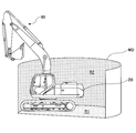
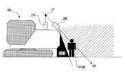
- FIG. 2 is a side view of the excavator 60 on which the image generating apparatus 100 is mounted.
- the excavator 60 includes a crawler type lower traveling body 61, a turning mechanism 62, and an upper turning body 63.
- the upper turning body 63 is mounted on the lower traveling body 61 via the turning mechanism 62 so as to be turnable around the turning axis PV.
- a cab (cab) 64 is provided on the front left side of the upper swing body 63, and a digging attachment E is provided on the front center.
- Cameras 2 (right camera 2R and rear camera 2B) are provided on the right and rear surfaces of the upper swing body 63.
- the display unit 5 is installed at a position in the cab 64 that is easily visible to the driver.
- the control unit 1 includes a computer having a CPU (Central Processing Unit), RAM (Random Access Memory), ROM (Read Only Memory), NVRAM (Non-Volatile Random Access Memory), and the like.
- CPU Central Processing Unit
- RAM Random Access Memory
- ROM Read Only Memory
- NVRAM Non-Volatile Random Access Memory
- programs corresponding to each of the coordinate association unit 10 and the output image generation unit 11 described later are stored in the ROM or NVRAM.
- the CPU performs processing by executing a program corresponding to each means while using the RAM as a temporary storage area.
- the camera 2 is a device for acquiring an input image that reflects the periphery of the excavator 60, and includes a right side camera 2R and a rear camera 2B.
- the right side camera 2R and the rear camera 2B are attached to the right side surface and the rear side surface of the upper swing body 63 so that, for example, an area that is a blind spot of the driver in the cab 64 can be photographed (see FIG. 2).
- Each of the right side camera 2R and the rear camera 2B includes an image sensor such as a CCD (Charge-Coupled Device) or a CMOS (Complementary Metal-Oxide Semiconductor).
- the camera 2 may be attached to a position other than the right side and the rear side of the upper swing body 63 (for example, the front side and the left side), and a wide-angle lens or a fisheye lens is attached so that a wide range can be photographed. It may be.
- the camera 2 acquires an input image according to a control signal from the control unit 1, and outputs the acquired input image to the control unit 1.
- the corrected input image obtained by correcting apparent distortion and tilt caused by using these lenses is transmitted to the control unit 1.
- the camera 2 may output the acquired input image to the control unit 1 as it is without correcting it. In that case, the control unit 1 corrects apparent distortion and tilt.
- the input unit 3 is a device that allows an operator to input various types of information to the image generation device 100, and includes, for example, a touch panel, a button switch, a pointing device, a keyboard, and the like.
- the storage unit 4 is a device for storing various information, and includes, for example, a hard disk, an optical disk, or a semiconductor memory.
- the display unit 5 is a device for displaying image information, and includes, for example, a liquid crystal display or a projector installed in a cab 64 (see FIG. 2) of a construction machine.
- the display unit 5 displays various images output from the control unit 1.
- the image generating apparatus 100 generates a processing target image based on the input image, and performs an image conversion process on the processing target image so that the positional relationship with the surrounding obstacles and a sense of distance can be intuitively grasped.
- An output image to be generated may be generated, and the output image may be presented to the driver.
- “Processing target image” is an image to be subjected to image conversion processing (for example, scale conversion, affine transformation, distortion conversion, viewpoint conversion processing) generated based on the input image.
- image conversion processing for example, scale conversion, affine transformation, distortion conversion, viewpoint conversion processing
- an input image obtained by a camera that images the ground surface from above and includes a horizontal image (for example, an empty portion) with a wide angle of view may be used in the image conversion process.
- the input image is projected onto a predetermined spatial model so that the image in the horizontal direction is not unnaturally displayed (for example, the sky portion is not treated as being on the ground surface).
- an image suitable for image conversion processing can be obtained by reprojecting the projected image projected on the space model onto another two-dimensional plane.
- the processing target image may be used as an output image as it is without performing an image conversion process.
- the “spatial model” is a projection target of the input image, and is at least a plane or curved surface other than the processing target image plane on which the processing target image is located (for example, a plane parallel to the processing target image plane, or a processing target Plane or curved surface forming an angle with the image plane).
- the image generation apparatus 100 may generate an output image by performing image conversion processing on the projected image projected on the space model without generating a processing target image. Further, the projection image may be used as an output image as it is without being subjected to image conversion processing.
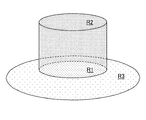
- 3A and 3B are diagrams illustrating an example of a spatial model MD on which an input image is projected.
- 3A shows the relationship between the excavator 60 and the space model MD when the excavator 60 is viewed from the side
- FIG. 3B shows the relationship between the excavator 60 and the space model MD when the excavator 60 is viewed from above. The relationship is shown.
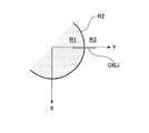
- the space model MD has a semi-cylindrical shape.
- the inside of the bottom surface of the semi-cylindrical shape includes a plane region R1, and the inside of the side surface includes a curved surface region R2.
- FIG. 4 is a diagram illustrating an example of the relationship between the space model MD and the processing target image plane.
- the processing target image plane R3 is a plane including the plane area R1 of the spatial model MD, for example.
- the space model MD is shown in a cylindrical shape, unlike the semicylindrical shape as shown in FIG. 3, but the spatial model MD is either a semicylindrical shape or a cylindrical shape. It may be.
- the processing target image plane R3 may be a circular area including the plane area R1 of the spatial model MD, or may be an annular area not including the plane area R1 of the spatial model MD.
- the coordinate associating unit 10 includes coordinates on the input image plane where the input image captured by the camera 2 is located (also referred to as input coordinates) and coordinates on the space model MD (also referred to as space coordinates). Are provided for associating coordinates (sometimes referred to as projection coordinates) on the processing target image plane R3. For example, various parameters relating to the camera 2 such as optical center, focal length, CCD size, optical axis direction vector, camera horizontal direction vector, projection method, etc., which are set in advance or input via the input unit 3 And the coordinates on the input image plane, the coordinates on the space model MD, and the processing target image based on the predetermined positional relationship among the input image plane, the spatial model MD, and the processing target image plane R3. The coordinates on the plane R3 are associated with each other. These correspondences are stored in the input image / space model correspondence map 40 and the space model / processing object image correspondence map 41 of the storage unit 4.
- the coordinate association unit 10 associates the coordinates on the space model MD with the coordinates on the processing target image plane R3 and the spatial model / processing target of the corresponding relationship. Storage in the image correspondence map 41 is omitted.
- the output image generation unit 11 is a means for generating an output image.
- the output image generation unit 11 associates the coordinates on the processing target image plane R3 and the coordinates on the output image plane on which the output image is located, for example, by performing scale conversion, affine transformation, or distortion conversion on the processing target image. .
- the correspondence relationship is stored in the processing target image / output image correspondence map 42 of the storage unit 4.
- the output image generation unit 11 refers to the input image / space model correspondence map 40 and the space model / processing object image correspondence map 41 stored in the coordinate association unit 10, and determines the value of each pixel (for example, luminance) Value, hue value, saturation value, etc.) and the value of each pixel in the input image are associated to generate an output image.
- the output image generation unit 11 is preset or input via the input unit 3, the optical center of the virtual camera, the focal length, the CCD size, the optical axis direction vector, the camera horizontal direction vector, and the projection method. And the like, the coordinates on the processing target image plane R3 are associated with the coordinates on the output image plane where the output image is located.
- the correspondence relationship is stored in the processing target image / output image correspondence map 42 of the storage unit 4.
- the output image generation unit 11 refers to the input image / space model correspondence map 40 and the space model / processing target image correspondence map 41 stored in the coordinate association unit 10, and the value of each pixel in the output image (for example, Brightness value, hue value, saturation value, etc.) and the value of each pixel in the input image are associated with each other to generate an output image.
- the value of each pixel in the output image for example, Brightness value, hue value, saturation value, etc.
- the output image generation unit 11 may generate the output image by changing the scale of the processing target image without using the concept of the virtual camera.
- the output image generation unit 11 associates the coordinates on the space model MD with the coordinates on the output image plane according to the applied image conversion processing. Then, the output image generation unit 11 refers to the input image / spatial model correspondence map 40, and the value of each pixel in the output image (for example, luminance value, hue value, saturation value, etc.) and the input image. An output image is generated in association with the value of each pixel. In this case, the output image generation unit 11 omits the correspondence between the coordinates on the processing target image plane R3 and the coordinates on the output image plane, and the storage of the correspondence relationship in the processing target image / output image correspondence map 42. To do.
- the coordinate associating unit 10 can associate the input coordinates on the input image plane with the spatial coordinates on the space model using, for example, a Hamilton quaternion.
- FIG. 5 is a diagram for explaining the correspondence between the coordinates on the input image plane and the coordinates on the space model.
- the input image plane of the camera 2 is represented as one plane in the UVW rectangular coordinate system with the optical center C of the camera 2 as the origin, and the spatial model is represented as a three-dimensional plane in the XYZ rectangular coordinate system.
- the coordinate association unit 10 converts the coordinates on the space model (coordinates on the XYZ coordinate system) to coordinates on the input image plane (coordinates on the UVW coordinate system), so that the origin of the XYZ coordinate system is optically converted.
- the XYZ coordinate system is rotated so that the X axis is aligned with the U axis, the Y axis is aligned with the V axis, and the Z axis is aligned with the ⁇ W axis.
- the sign “ ⁇ ” means that the direction is opposite. This is because the UVW coordinate system has the + W direction in front of the camera, and the XYZ coordinate system has the ⁇ Z direction in the vertically downward direction.
- each of the cameras 2 has an individual UVW coordinate system.
- the coordinate association unit 10 translates and rotates the XYZ coordinate system with respect to each of the plurality of UVW coordinate systems.
- the XYZ coordinate system is translated so that the optical center C of the camera 2 is the origin of the XYZ coordinate system, and then the Z axis is rotated so as to coincide with the ⁇ W axis. This is realized by rotating to coincide with the axis. Therefore, the coordinate matching unit 10 combines these two rotations into a single rotation calculation by describing this conversion as a Hamilton quaternion.
- the rotation for making one vector A coincide with another vector B corresponds to the process of rotating the vector A and the vector B by the angle formed by using the normal line of the plane formed by the vectors A and B as an axis.
- the rotation angle is ⁇
- the angle ⁇ is expressed as follows from the inner product of the vector A and the vector B.
- the unit vector N of the normal line between the vector A and the vector B is expressed as follows from the outer product of the vector A and the vector B.
- the quaternion is a super complex number that satisfies the following conditions, where i, j, and k are imaginary units.
- the quaternion Q is expressed as follows, where the real component is t and the pure imaginary components are a, b, and c.
- the quaternion Q can express a three-dimensional vector (a, b, c) with pure imaginary components a, b, c while setting the real component t to 0 (zero).
- a rotation operation with an arbitrary vector as an axis can be expressed by each component of t, a, b, and c.
- the quaternion Q can be expressed as a single rotation operation by integrating a plurality of continuous rotation operations.
- a point D (ex, ey, ez) when an arbitrary point S (sx, sy, sz) is rotated by an angle ⁇ with an arbitrary unit vector C (l, m, n) as an axis is shown below. It can be expressed as
- the point X on the X axis in the XYZ coordinate system is moved to the point X ′. Therefore, the point X ′ is expressed as follows.
- a quaternion R representing “a rotation that makes the X axis coincide with the U axis” is expressed as follows.
- a coordinate P ′ when an arbitrary coordinate P on the space model (XYZ coordinate system) is expressed by a coordinate on the input image plane (UVW coordinate system) is expressed as follows.
- the coordinate matching unit 10 thereafter executes the calculation to convert the coordinates on the space model (XYZ coordinate system) to the input image plane (UVW coordinate system). ) Can be converted to the above coordinates.
- the coordinate association unit 10 After converting the coordinates on the space model (XYZ coordinate system) to the coordinates on the input image plane (UVW coordinate system), the coordinate association unit 10 determines the optical center C (coordinates on the UVW coordinate system) of the camera 2 and the space.
- An incident angle ⁇ formed by a line segment CP ′ connecting an arbitrary coordinate P on the model with a coordinate P ′ represented in the UVW coordinate system and the optical axis G of the camera 2 is calculated.
- the coordinate association unit 10 includes an intersection point E between the plane H and the optical axis G, and a coordinate P ′ in a plane H that is parallel to the input image plane R4 (for example, CCD plane) of the camera 2 and includes the coordinate P ′.
- the coordinate associating unit 10 decomposes the calculated image height h into U and V components on the UV coordinate system based on the deflection angle ⁇ , and is a numerical value corresponding to the pixel size per pixel of the input image plane R4. Divide.
- the coordinate association unit 10 can associate the coordinates P (P ′) on the space model MD with the coordinates on the input image plane R4.
- the coordinate association unit 10 associates the coordinates on the space model MD with the coordinates on one or more input image planes R4 existing for each camera, and the coordinates on the space model MD.
- the correspondence between the camera identifier and the coordinates on the input image plane R4 is stored in the input image / space model correspondence map 40.
- the coordinate association unit 10 calculates the coordinate conversion using the quaternion, and therefore provides an advantage that no gimbal lock is generated unlike the case of calculating the coordinate conversion using the Euler angle.
- the coordinate association unit 10 is not limited to the one that calculates the coordinate conversion using the quaternion, and may perform the coordinate conversion using the Euler angle.
- the coordinate association unit 10 uses the coordinates P (P ′) on the space model MD as the input image planes relating to the camera having the smallest incident angle ⁇ .
- the coordinates may be associated with the coordinates on R4, or may be associated with the coordinates on the input image plane R4 selected by the operator.
- FIG. 6A and 6B are diagrams for explaining the association between coordinates by the coordinate association unit 10.
- the coordinate associating unit 10 causes each of the line segments connecting the coordinates on the input image plane R4 of the camera 2 and the coordinates on the spatial model MD corresponding to the coordinates to pass through the optical center C of the camera 2, Associate both coordinates.
- the coordinate association unit 10 associates the coordinate K1 on the input image plane R4 of the camera 2 with the coordinate L1 on the plane area R1 of the spatial model MD, and on the input image plane R4 of the camera 2.
- the coordinate K2 is associated with the coordinate L2 on the curved surface region R2 of the space model MD.
- both the line segment K1-L1 and the line segment K2-L2 pass through the optical center C of the camera 2.
- the coordinate association unit 10 determines according to each projection method.
- the coordinates K1 and K2 on the input image plane R4 of the camera 2 are associated with the coordinates L1 and L2 on the space model MD.
- the line segment K1-L1 and the line segment K2-L2 do not pass through the optical center C of the camera 2.
- FIG. 6B is a diagram illustrating a correspondence relationship between coordinates on the curved surface region R2 of the spatial model MD and coordinates on the processing target image plane R3.
- the coordinate association unit 10 is a parallel line group PL located on the XZ plane, and introduces a parallel line group PL that forms an angle ⁇ with the processing target image plane R3, so that the curved surface region R2 of the spatial model MD is introduced.
- the upper coordinates and the coordinates on the processing target image plane R3 corresponding to the coordinates are both put on one of the parallel line groups PL, and the two coordinates are associated with each other.
- the coordinate association unit 10 associates both coordinates on the assumption that the coordinate L2 on the curved surface region R2 of the spatial model MD and the coordinate M2 on the processing target image plane R3 are on a common parallel line.
- the coordinate associating unit 10 can associate the coordinates on the plane area R1 of the spatial model MD with the coordinates on the processing target image plane R3 using the parallel line group PL in the same manner as the coordinates on the curved surface area R2.
- the coordinate association unit 10 associates the spatial coordinates on the spatial model MD with the projection coordinates on the processing target image plane R3, and the coordinates on the spatial model MD and the processing target image R3.
- the coordinates are associated and stored in the spatial model / processing object image correspondence map 41.
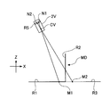
- each line segment connecting the coordinates on the output image plane R5 of the virtual camera 2V and the coordinates on the processing target image plane R3 corresponding to the coordinates passes through the optical center CV of the virtual camera 2V. As shown in FIG.
- the output image generation unit 11 associates the coordinates N1 on the output image plane R5 of the virtual camera 2V with the coordinates M1 on the processing target image plane R3 (plane area R1 of the spatial model MD), and
- the coordinate N2 on the output image plane R5 of the virtual camera 2V is associated with the coordinate M2 on the processing target image plane R3.
- both the line segment M1-N1 and the line segment M2-N2 pass through the optical center CV of the virtual camera 2V.
- the output image generation unit 11 performs each projection method. Accordingly, the coordinates N1 and N2 on the output image plane R5 of the virtual camera 2V are associated with the coordinates M1 and M2 on the processing target image plane R3.
- the line segment M1-N1 and the line segment M2-N2 do not pass through the optical center CV of the virtual camera 2V.
- the output image generation unit 11 associates the coordinates on the output image plane R5 with the coordinates on the processing target image plane R3, and the coordinates on the output image plane R5 and the processing target image R3.
- the coordinates are associated and stored in the processing target image / output image correspondence map 42.
- the output image generation unit 11 refers to the input image / spatial model correspondence map 40 and the spatial model / processing target image correspondence map 41 stored in the coordinate association unit 10 and inputs the values of the respective pixels in the output image.
- An output image is generated in association with the value of each pixel in the image.
- FIG. 6D is a combination of FIGS. 6A to 6C, and shows the positional relationship among the camera 2, the virtual camera 2V, the plane area R1 and the curved area R2 of the space model MD, and the processing target image plane R3. Show.
- FIG. 7A is a diagram when the angle ⁇ is formed between the parallel line group PL located on the XZ plane and the processing target image plane R3.
- FIG. 7B is a diagram in the case where an angle ⁇ 1 ( ⁇ 1> ⁇ ) is formed between the parallel line group PL positioned on the XZ plane and the processing target image plane R3.
- the coordinates La to Ld on the curved surface region R2 of the spatial model MD in FIGS. 7A and 7B correspond to the coordinates Ma to Md on the processing target image plane R3, respectively.
- the distance between the coordinates La to Ld in FIG. 7A is equal to the distance between the coordinates La to Ld in FIG. 7B.
- the parallel line group PL is assumed to exist on the XZ plane, but actually, it extends radially from all points on the Z axis toward the processing target image plane R3. Exists.
- the Z axis is referred to as a “reprojection axis”.
- the interval between the coordinates Ma to Md on the processing target image plane R3 decreases linearly as the angle between the parallel line group PL and the processing target image plane R3 increases. . That is, the interval between the coordinates Ma to Md decreases uniformly regardless of the distance between the curved surface region R2 of the space model MD and each of the coordinates Ma to Md.
- the interval between the coordinate groups on the plane region R1 of the spatial model MD does not change.
- the change in the interval between these coordinate groups is such that only the image portion corresponding to the image projected on the curved surface region R2 of the spatial model MD is linearly enlarged or reduced among the image portions on the output image plane R5 (see FIG. 6C).
- FIG. 8A is a diagram in the case where all of the auxiliary line groups AL positioned on the XZ plane extend from the start point T1 on the Z axis toward the processing target image plane R3.
- FIG. 8B is a diagram in the case where all of the auxiliary line group AL extends from the start point T2 (T2> T1) on the Z axis toward the processing target image plane R3.
- the coordinates La to Ld on the curved surface region R2 of the spatial model MD in FIGS. 8A and 8B correspond to the coordinates Ma to Md on the processing target image plane R3, respectively.
- the coordinates Mc and Md are not shown because they are outside the region of the processing target image plane R3.
- the distance between the coordinates La to Ld in FIG. 8A is equal to the distance between the coordinates La to Ld in FIG. 8B.
- the auxiliary line group AL exists on the XZ plane for convenience of explanation, but actually, it exists radially from an arbitrary point on the Z axis toward the processing target image plane R3. is doing. 7A and 7B, the Z axis in this case is referred to as a “reprojection axis”.
- the interval between the coordinates Ma to Md on the processing target image plane R3 is nonlinear as the distance (height) between the starting point of the auxiliary line group AL and the origin O increases. To decrease. That is, the greater the distance between the curved surface region R2 of the space model MD and each of the coordinates Ma to Md, the greater the reduction width of each interval.
- the interval between the coordinate groups on the plane region R1 of the spatial model MD does not change.
- the change in the interval between these coordinate groups corresponds to the image projected on the curved surface region R2 of the spatial model MD in the image portion on the output image plane R5 (see FIG. 6C), as in the case of the parallel line group PL. It means that only the image portion is enlarged or reduced nonlinearly.
- the image generating apparatus 100 can affect the curved surface area of the spatial model MD without affecting the image portion (for example, the road surface image) of the output image corresponding to the image projected on the planar area R1 of the spatial model MD.
- An image portion (for example, a horizontal image) of the output image corresponding to the image projected on R2 can be enlarged or reduced linearly or nonlinearly.
- an object positioned around the excavator 60 (the periphery is seen from the excavator 60 in the horizontal direction without affecting the road surface image in the vicinity of the excavator 60 (virtual image when the excavator 60 is viewed from directly above).
- the object in the image at the time) can be enlarged or reduced quickly and flexibly, and the visibility of the blind spot area of the excavator 60 can be improved.
- the output image is directly generated from the image projected on the space model MD, and the image projected on the space model MD is reprojected on the processing target image. A difference from the case of generating an output image from the reprojected processing target image will be described.
- FIG. 9A is a diagram in a case where an angle ⁇ is formed between the parallel line group PL positioned on the XZ plane and the processing target image plane R3, and FIG. 9B is a parallel line group PL positioned on the XZ plane.
- the position of the plane area R1 and the curved area R2, the processing target image plane R3, the output image plane R5 of the virtual camera 2V employing the normal projection (h ftan ⁇ ), and the optical center CV in FIG.
- Each of 9B is common.
- the coordinate M1 on the processing target image plane R3 including the plane region R1 corresponds to the coordinate N1 on the output image plane R5, and the coordinate L2 on the curved surface region R2 is on the processing target image plane R3.
- a distance D1 (D3) indicates a distance on the X axis between the center point of the output image plane R5 (intersection with the optical axis GV of the virtual camera 2V) and the coordinate N1.
- a distance D2 (D4) indicates a distance on the X axis between the center point of the output image plane R5 and the coordinate N2.
- the distance D2 (see FIG. 9A) when the angle between the parallel line group PL and the processing target image plane R3 is ⁇ increases as the angle decreases.
- the distance D4 (see FIG. 9B) is obtained when the angle is ⁇ 2.
- the distance D1 when the angle is ⁇ (see FIG. 9A) is constant regardless of the change in the angle, and is equal to the distance D3 when the angle is ⁇ 2 (see FIG. 9B).
- the distance D2 changes to the distance D4 and the distance D1 (D3) is not changed, as in the operation described with reference to FIGS. 7A and 7B and FIGS. 8A and 8B. It means that only the image portion (for example, a horizontal image) corresponding to the image projected on the curved surface region R2 of the spatial model MD is enlarged or reduced among the upper image portions.
- the image portion for example, a horizontal image
- FIG. 10 is a diagram when the angle ⁇ is formed between the parallel line group PL located on the XZ plane and the processing target image plane R3.
- the output image generation unit 11 includes a coordinate M1 on the processing target image plane R3 (plane area R1) and a coordinate N1 on the output image plane R5, and a line segment M1-N1 has an optical center CV.
- the coordinates M2 on the processing target image plane R3 and the coordinates N2 on the output image plane R5 corresponding to the coordinates L2 on the curved surface area R2, and the line segment M2-N2 has the optical center CV. Match to pass.
- the output image generation unit 11 passes the coordinates M1 on the processing target image plane R3 (plane area R1) and the coordinates N1 on the output image plane R5 so that the line segment M1-N1 passes through the optical center CV (
- the coordinates on the output image plane R5 and the coordinates on the processing target image plane R3 are associated with each other.
- the line segment M1-N1 does not pass through the optical center CV of the virtual camera 2V.
- FIG. 11 is a flowchart of processing target image generation processing (steps S1 to S3) and output image generation processing (steps S4 to S6). Assume that the arrangement of the camera 2 (input image plane R4), the space model (plane area R1 and curved surface area R2), and the processing target image plane R3 is determined in advance.
- control unit 1 associates the coordinates on the processing target image plane R3 with the coordinates on the space model MD by the coordinate association unit 10 (step S1).
- the coordinate association unit 10 obtains an angle formed between the parallel line group PL and the processing target image plane R3, and the parallel line group PL extending from one coordinate on the processing target image plane R3.
- One point that intersects the curved surface region R2 of the space model MD is calculated.
- the coordinate association unit 10 derives the coordinates on the curved surface region R2 corresponding to the calculated point as one coordinate on the curved surface region R2 corresponding to the one coordinate on the processing target image plane R3, and the correspondence relationship is derived. It is stored in the spatial model / processing object image correspondence map 41.
- the angle formed between the parallel line group PL and the processing target image plane R3 may be a value stored in advance in the storage unit 4 or the like, and is dynamically input by the operator via the input unit 3. It may be a value.
- the coordinate association unit 10 uses the one coordinate on the plane area R1 as the processing target image plane R3. It is derived as one coordinate corresponding to the one coordinate above, and the correspondence is stored in the space model / processing object image correspondence map 41.
- control unit 1 causes the coordinate association unit 10 to associate one coordinate on the space model MD derived by the above-described processing with a coordinate on the input image plane R4 (step S2).
- control unit 1 determines whether or not all the coordinates on the processing target image plane R3 are associated with the coordinates on the space model MD and the coordinates on the input image plane R4 (step S3). If it is determined that not all coordinates have been associated yet (NO in step S3), the processes in steps S1 and S2 are repeated.
- step S3 when it is determined that all the coordinates are associated (YES in step S3), the control unit 1 ends the processing target image generation process and then starts the output image generation process. Thereby, the output image generation unit 11 associates the coordinates on the processing target image plane R3 with the coordinates on the output image plane R5 (step S4).
- the output image generation unit 11 generates an output image by performing scale conversion, affine conversion, or distortion conversion on the processing target image. Then, the output image generation unit 11 processes the correspondence between the coordinates on the processing target image plane R3 and the coordinates on the output image plane R5, which are determined by the contents of the scale conversion, affine transformation, or distortion conversion performed.
- the target image / output image correspondence map 42 is stored.
- the output image generation unit 11 calculates the coordinates on the output image plane R5 from the coordinates on the target processing image plane R3 according to the adopted projection method.
- the correspondence relationship may be stored in the processing target image / output image correspondence map 42.
- the output image generation unit 11 acquires the coordinates of the optical center CV of the virtual camera 2V, A point that is a line segment extending from one coordinate on the output image plane R5 and that passes through the optical center CV may be calculated. Then, the output image generation unit 11 derives the coordinates on the processing target image plane R3 corresponding to the calculated point as one coordinate on the processing target image plane R3 corresponding to the one coordinate on the output image plane R5, and The correspondence relationship may be stored in the processing target image / output image correspondence map 42.
- control unit 1 causes the output image generation unit 11 to refer to the input image / space model correspondence map 40, the space model / processing target image correspondence map 41, and the processing target image / output image correspondence map 42 while referring to the input image / space model correspondence map 40.
- the control unit 1 causes the output image generation unit 11 to refer to the input image / space model correspondence map 40, the space model / processing target image correspondence map 41, and the processing target image / output image correspondence map 42 while referring to the input image / space model correspondence map 40.
- Correspondence between coordinates on the plane R4 and coordinates on the space model MD, correspondence between coordinates on the space model MD and coordinates on the processing target image plane R3, and coordinates on the processing target image plane R3 and output image plane Following the correspondence relationship with the coordinates on R5, the values (for example, the luminance value, the hue value, the saturation value, etc.) of the coordinates on the input image plane R4 corresponding to the coordinates on the output image plane R5 are included. get.
- control part 1 employs the acquired value as a value of each coordinate on corresponding output image plane R5 (step S5).
- the output image generation unit 11 sets each of the plurality of coordinates on the plurality of input image planes R4.
- a statistical value for example, an average value, a maximum value, a minimum value, an intermediate value, or the like
- the statistical value is adopted as the value of the one coordinate on the output image plane R5. Good.
- control unit 1 determines whether or not all the coordinate values on the output image plane R5 are associated with the coordinate values on the input image plane R4 (step S6). If it is determined that not all coordinate values have been associated yet (NO in step S6), the processes in steps S4 and S5 are repeated.
- control unit 1 when it is determined that all coordinate values are associated (YES in step S6), the control unit 1 generates an output image and ends the series of processes.
- the image generation apparatus 100 omits the processing target image generation processing, and sets “coordinates on the processing target image plane” in step S4 in the output image generation processing as “on the spatial model”. Read as "Coordinates”.
- the image generation apparatus 100 can generate a processing target image and an output image that allow the operator to intuitively grasp the positional relationship between the construction machine and the surrounding obstacle.
- the image generation apparatus 100 associates coordinates from the processing target image plane R3 to the input image plane R4 via the spatial model MD, whereby the coordinates on the processing target image plane R3 are displayed on the input image plane R4. It is possible to reliably correspond to one or a plurality of coordinates. Therefore, it is possible to quickly generate a higher-quality processing target image than in the case where the coordinate association is executed in the order from the input image plane R4 to the processing target image plane R3 through the space model MD. Note that, when coordinates are associated in the order from the input image plane R4 through the space model MD to the processing target image plane R3, each coordinate on the input image plane R4 is set to one or more on the processing target image plane R3.
- some of the coordinates on the processing target image plane R3 may not be associated with any coordinates on the input image plane R4. In such a case, it is necessary to perform an interpolation process or the like on some of the coordinates on the processing target image plane R3.
- the image generating apparatus 100 changes the angle formed between the parallel line group PL and the processing target image plane R3.
- the image generation apparatus 100 when changing the appearance of the output image, the image generation apparatus 100 simply rewrites the processing target image / output image correspondence map 42 by changing the values of various parameters relating to scale conversion, affine transformation, or distortion transformation.
- the desired output image (scale-converted image, affine-transformed image, or distortion-converted image) can be generated without rewriting the contents of the input image / space model correspondence map 40 and the space model / processing object image correspondence map 41.
- the image generation apparatus 100 simply changes the values of various parameters of the virtual camera 2V and rewrites the processing target image / output image correspondence map 42, thereby changing the input image / space.
- An output image (viewpoint conversion image) viewed from a desired viewpoint can be generated without rewriting the contents of the model correspondence map 40 and the space model / processing object image correspondence map 41.
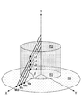
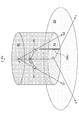
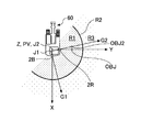
- FIG. 12A is a diagram showing the positional relationship between the camera 2 and the space model MD when the excavator 60 is viewed from above, as in FIG. 3B.
- FIG. 12B is a diagram illustrating the positional relationship between the camera 2 and the space model MD when the space model MD is viewed obliquely from above, similarly to FIG. 4.
- FIG. 12C is a diagram illustrating a processing target image generated by the image generation apparatus 100.
- the cylindrical central axis of the cylindrical spatial model MD coincides with the reprojection axis and the pivot axis PV (Z axis) of the excavator 60, and on the Y axis, in the Z axis direction.
- a rod-like object OBJ extending in parallel.
- the optical axis G1 of the rear camera 2B and the optical axis G2 of the right-side camera 2R intersect with the plane (XY plane) where the plane region R1 of the spatial model MD and the processing target image plane R3 are located, respectively.
- the optical axis G1 and the optical axis G2 intersect at a point J1 on the cylindrical central axis (reprojection axis). Note that the optical axis G1 and the optical axis G2 are twisted as long as each component when projected onto a plane parallel to the XY plane intersects at a point on the cylindrical central axis (reprojection axis). It may be in a positional relationship.
- the perpendicular drawn from the optical center of the rear camera 2B to the cylinder central axis is perpendicular to the perpendicular drawn from the optical center of the right camera 2R to the cylinder central axis (reprojection axis).
- the two perpendiculars are orthogonal to each other at the point J2 while existing on one plane parallel to the plane where the plane region R1 and the processing target image plane R3 are located. It may be located on another plane and have a twist position relationship.
- the image generation apparatus 100 can generate a processing target image as shown in FIG. 12C. That is, in FIG. 12C, a rod-like object OBJ extending parallel to the Z-axis direction on the Y-axis is a direction parallel to the Y-axis direction (right-side camera 2R) in the road surface image portion corresponding to the image projected onto the plane region R1. Extending in the direction of a straight line that passes through the optical center and the point on the object OBJ. In FIG.
- the rod-like object OBJ is a horizontal image portion corresponding to the image projected on the curved surface region R2 and is also in a direction parallel to the Y-axis direction (a point on the reprojection axis (parallel line group PL or auxiliary line). It extends in the direction of a straight line passing through the starting point of the group AL) and a point on the object OBJ. In other words, the object OBJ does not bend at the boundary between the road surface image portion and the horizontal image portion and extends linearly.
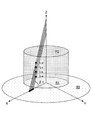
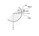
- FIGS. 13A to 13C are diagrams similar to FIGS. 12A to 12C, respectively.
- the cylindrical center axis of the cylindrical space model MD coincides with the reprojection axis and the pivot axis PV (Z axis) of the shovel 60, and is parallel to the Z axis direction on the Y axis.
- a rod-like object OBJ extending to Furthermore, a rod-like object OBJ1 extending in parallel with the Z-axis direction from the XY plane also exists in the direction of the optical axis G2 of the right-side camera 2R.
- the optical axis G1 of the rear camera 2B and the optical axis G2 of the right-side camera 2R are the planes on which the plane region R1 of the spatial model MD and the processing target image plane R3 are located, as in the positional relationship shown in FIG. 12B. Intersects the (XY plane).
- the optical axis G1 and the optical axis G2 intersect at a point J1 on the cylindrical central axis (reprojection axis). If each of the components projected onto a plane parallel to the XY plane intersects at a point on the cylindrical central axis (reprojection axis), the optical axis G1 and the optical axis G2 are twisted positions. You may be in a relationship.
- the perpendicular drawn from the optical center of the rear camera 2B to the cylindrical center axis is perpendicular to the perpendicular drawn from the optical center of the right camera 2R to the cylindrical center axis (reprojection axis).
- the perpendicular drawn from the optical center of the rear camera 2B to the cylinder central axis (reprojection axis) is a perpendicular drawn from the optical center of the right camera 2R to the perpendicular and the point J2 not on the cylinder central axis (reprojection axis). Orthogonal.
- the optical centers of the rear camera 2B and the right-side camera 2R exist on one plane parallel to the plane where the plane region R1 and the processing target image plane R3 are located.
- the optical centers of the rear camera 2B and the right-side camera 2R may be located on different planes, and the perpendiculars to each other may be in a twisted position relationship.
- the image generation device 100 Based on the positional relationship between the camera 2 and the space model MD shown in FIGS. 13A and 13B, the image generation device 100 generates a processing target image as shown in FIG. 13C.
- a rod-like object OBJ extending parallel to the Z-axis direction on the Y-axis is a direction slightly away from the Y-axis direction (the right side camera 2R of the right camera 2R) in the road surface image portion corresponding to the image projected onto the plane region R1. (The direction of a straight line passing through the optical center and a point on the object OBJ).
- the bar-shaped object OBJ is parallel to the Y-axis direction in the horizontal image portion corresponding to the image projected on the curved surface region R2 (a point on the reprojection axis (the start point of the parallel line group PL or the auxiliary line group AL)). And the direction of a straight line passing through a point on the object OBJ. In other words, the object OBJ is slightly bent at the boundary between the road surface image portion and the horizontal image portion.
- a rod-like object OBJ1 extending parallel to the Z-axis direction in the direction of the optical axis G2 of the right-side camera 2R is a road surface image portion corresponding to the image projected on the plane region R1. It extends in a direction parallel to the direction of the optical axis G2 (the direction of a straight line passing through the optical center of the right side camera 2R and a point on the object OBJ).
- the rod-like object OBJ1 is a horizontal image portion corresponding to the image projected on the curved surface region R2, and is also in a direction parallel to the optical axis G2 direction (a point on the reprojection axis (a parallel line group PL or an auxiliary line group AL). Extending in the direction of a straight line passing through a starting point) and a point on the object OBJ1. In other words, the object OBJ1 extends linearly without being bent at the boundary between the road surface image portion and the horizontal image portion.
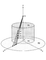
- FIGS. 14A to 14C are views similar to FIGS. 12A to 12C, respectively.
- the cylindrical center axis of the cylindrical space model MD coincides with the reprojection axis and the pivot axis PV (Z axis) of the shovel 60, and is parallel to the Z axis direction on the Y axis.
- a rod-like object OBJ extending to Further, a rod-like object OBJ2 that extends in parallel with the Z-axis direction from the XY plane also exists in the direction of the optical axis G2 of the right-side camera 2R.
- the optical axis G1 of the rear camera 2B and the optical axis G2 of the right-side camera 2R are planes on which the plane region R1 of the spatial model MD and the processing target image plane R3 are located, as in the positional relationship shown in FIG. 12B. Intersects the (XY plane).
- the perpendicular drawn from the optical center of the rear camera 2B to the cylindrical center axis (reprojection axis) is perpendicular to the perpendicular drawn from the optical center of the right camera 2R to the cylindrical center axis (reprojection axis). .
- the optical centers of the rear camera 2B and the right-side camera 2R exist on one plane parallel to the plane on which the plane region R1 and the processing target image plane R3 are located.
- the optical centers of the rear camera 2B and the right camera 2R may be located on different planes, and the perpendiculars to each other may be in a twisted position relationship.
- the optical axis G1 and the optical axis G2 do not intersect on the cylinder center axis (reprojection axis), but intersect at a point J1 that is not on the cylinder center axis (reprojection axis). Note that the optical axis G1 and the optical axis G2 are twisted if each of the components when projected onto a plane parallel to the XY plane intersects at a point that is not on the cylindrical central axis (reprojection axis). It may be in a positional relationship.
- the image generation apparatus 100 generates a processing target image as illustrated in FIG. 14C based on the positional relationship between the camera 2 and the space model MD.
- a rod-like object OBJ2 extending in parallel with the Z-axis direction in the direction of the optical axis G2 of the right-side camera 2R is parallel to the optical axis G2 direction in the road surface image portion corresponding to the image projected onto the plane region R1. (In the direction of a straight line passing through the optical center of the right camera 2R and a point on the object OBJ).
- the rod-shaped object OBJ2 is a horizontal image portion corresponding to the image projected on the curved surface region R2 in a direction substantially parallel to the Y-axis direction (a point on the reprojection axis (the start point of the parallel line group PL or the auxiliary line group AL). And a direction of a straight line passing through a point on the object OBJ2.
- the object OBJ2 is slightly bent at the boundary between the road surface image portion and the horizontal image portion.
- a rod-like object OBJ extending parallel to the Z-axis direction on the Y-axis is a direction parallel to the Y-axis direction in the road surface image portion corresponding to the image projected onto the plane region R1 ( Extending in the direction of a straight line passing through the optical center of the right camera 2R and a point on the object OBJ).
- the bar-shaped object OBJ is a horizontal image portion corresponding to the image projected onto the curved surface region R2, and is also in a direction parallel to the Y-axis direction (a point on the reprojection axis (the start point of the parallel line group PL or the auxiliary line group AL).
- a direction of a straight line passing through a point on the object OBJ In other words, the object OBJ extends in a straight line without bending at the boundary between the road surface image portion and the horizontal image portion.
- the image generating apparatus 100 arranges the spatial model MD so that the cylindrical central axis (reprojection axis) of the spatial model MD intersects the optical axis of the camera, and thereby in the optical axis direction of the camera.
- the processing target image can be generated so that a certain object does not bend at the boundary between the road surface image portion and the horizontal image portion. This advantage can be obtained both when there is only one camera and when there are three or more cameras.
- the image generation apparatus 100 is configured so that the perpendiculars drawn from the optical centers of the rear camera 2B and the right camera 2R to the cylindrical center axis (reprojection axis) of the spatial model MD are perpendicular to each other.
- the MD By arranging the MD, it is possible to generate the processing target image so that the object right next to and right behind the excavator 60 is not bent at the boundary between the road surface image portion and the horizontal image portion. This advantage can also be obtained when there are three or more cameras.
- the positional relationship and operational effects between the camera 2 (right-side camera 2R, rear camera 2B) and the space model MD shown in FIGS. 12A to 14C are as follows when the image generation apparatus 100 generates a processing target image.
- a similar effect can be obtained even when the image generation apparatus 100 does not generate a processing target image (when the processing target image plane R3 does not exist).
- the processing target images shown in FIGS. 12C, 13C, and 14C are read as output images generated using the images projected on the space model MD.
- FIG. 15 is a display example when an output image generated using input images of two cameras 2 (right camera 2R and rear camera 2B) mounted on the excavator 60 is displayed on the display unit 5.
- the image generation apparatus 100 projects a part of the input image onto the plane area R1 of the spatial model MD, and projects another part of the input image onto the curved area R2 of the space model MD, and then processes the image plane R3. Re-projected to generate a processing target image.
- the image generation device 100 corresponds to an image that looks down from the sky near the excavator 60 and an image that is projected to the curved surface region R2, corresponding to the image projected to the planar region R1, based on the generated processing target image. That is, the image is displayed in combination with the image of the periphery viewed from the excavator 60 corresponding to the image re-projected on the processing target image plane R3.
- the output image is generated by performing image conversion processing (for example, viewpoint conversion processing) on the image projected on the space model MD.
- image conversion processing for example, viewpoint conversion processing
- the output image is trimmed in a circle so that the image when the excavator 60 performs the turning motion can be displayed without a sense of incongruity. That is, the output image is generated so that the center CTR of the circle is on the cylindrical central axis of the space model MD and on the turning axis PV of the excavator 60, and the center of the output image depends on the turning operation of the excavator 60. Displayed to rotate around CTR. In this case, the cylindrical central axis of the space model MD may or may not coincide with the reprojection axis.
- the radius of the space model MD is, for example, 5 meters.
- the angle formed by the parallel line group PL with the processing target image plane R3 or the starting point height of the auxiliary line group AL is separated from the turning center of the excavator 60 by the maximum reachable distance (for example, 12 meters) of the excavation attachment E.
- the maximum reachable distance for example, 12 meters
- the output image may be a CG image of the excavator 60 arranged so that the front of the excavator 60 coincides with the upper part of the screen of the display unit 5 and the turning center thereof coincides with the center CTR. This is to make the positional relationship between the shovel 60 and the object appearing in the output image easier to understand.
- a frame image including various kinds of information such as an orientation may be arranged around the output image.
- the image generating apparatus 100 is projected onto the curved surface region R2 without affecting the image portion in the output image corresponding to the image projected onto the planar region R1. Only the image portion in the output image corresponding to the image reprojected on the processing target image plane R3 can be enlarged or reduced. Further, as shown in FIG. 10, in order to look down on the image portion of the output image corresponding to the image projected onto the curved surface region R2 and re-projected onto the processing target image plane R3, the image portion is displayed on the display unit 5. It can also be moved to an arbitrary position (for example, the center) in the screen area.
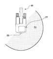
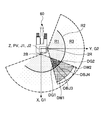
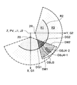
- FIG. 16A is a diagram illustrating a positional relationship between the imaging range of the camera 2 and the space model MD when the excavator 60 is viewed from above
- FIG. 16B is a camera when the space model MD is viewed from obliquely above. It is a figure which shows the positional relationship between 2 imaging range and space model MD
- FIG. 16C is a diagram illustrating a processing target image generated by the image generation device 100 based on an input image captured by the camera 2 installed as illustrated in FIGS. 16A and 16B.
- the cylindrical central axis of the cylindrical space model MD coincides with the reprojection axis and the pivot axis PV (Z axis) of the excavator 60.
- the pivot axis PV Z axis
- the distance between the turning axis PV and the object OBJ3 is smaller than the radius of the space model MD.
- the distance between the pivot axis PV and the object OBJ4 is larger than the radius of the space model MD.
- the imaging range of the rear camera 2B is represented by a fan-shaped one-dot chain line
- the imaging range of the right-side camera 2R is represented by a fan-shaped broken line.
- the object OBJ3 is in a region where the imaging range of the rear camera 2B and the imaging range of the right-side camera 2R overlap (hereinafter referred to as “imaging range overlapping region”) and inside the curved surface region R2 of the spatial model MD. It is included in the space.
- the object OBJ4 is included in a space within the imaging range overlapping region and outside the curved surface region R2 of the space model MD.
- the coordinates of the input image portion corresponding to the imaging range overlapping region are partly a region DG1 (see FIG. 16A) of the planar region R1 and a region of the curved surface region R2 in the spatial model MD. Associated with coordinates in DY1 (see FIG. 16B).
- Other portions originally, portions that can be associated with coordinates in one region DG2 (see FIG. 16A) of the planar region R1 and one region DY2 (see FIG. 16B) of the curved region R2 in the space model MD) are on the space model MD. It is not related to the coordinates of. This is because the coordinates in a part of the input image portion corresponding to the imaging range overlapping area in the input image captured by the right-side camera 2R are associated with the coordinates in the one area DG2, DY2.
- the coordinates of the input image portion corresponding to the imaging range overlapping region are partly a region DG2 (see FIG. 16A) and a curved surface region of the planar region R1 in the spatial model MD.
- R2 is associated with coordinates in a region DY2 (see FIG. 16B).
- Other portions originally, portions that can be associated with coordinates in one region DG1 (see FIG. 16A) of the planar region R1 and one region DY1 (see FIG. 16B) of the curved region R2 in the spatial model MD) are the spatial model MD. It is not related to the coordinates above. This is because the coordinates in a part of the input image portion corresponding to the imaging range overlapping area in the input image captured by the rear camera 2B are associated with the coordinates in the areas DG1 and DY1.
- one area DY1, DY2 of the curved surface area R2 in the space model MD is associated with one area DW1, DW2 on the processing target image plane R3, as shown in FIG. 17 or FIG. 18, respectively.
- the image part is projected on each of the regions DG1 and DG2 of the planar region R1 in the space model MD.
- a small portion of the object OBJ3 that is in contact with the road surface remains as a road surface pattern, and the other major portion extending from the road surface (an image portion obtained by viewing the object OBJ3 from the horizontal direction and not treated as a road surface pattern). ) Disappears (see FIG. 16C).
- the input images captured by the rear camera 2B and the right-side camera 2R representing the object OBJ4 that is included in the space within the imaging range overlapping region and outside the curved surface region R2 of the space model MD.
- the portion is projected onto each of the regions DY1 and DY2 in the curved surface region R2 of the space model MD.
- the object OBJ4 is projected on each of the regions DW1 and DW2 of the processing target image plane R3, and is divided into two objects OBJ4-1 and OBJ4-2, and appears in the regions DW1 and DW2 respectively (see FIG. 16C).
- FIGS. 17 and 18 are diagrams illustrating processing target images generated by the image generation apparatus 100 based on an input image captured by the camera 2 installed as illustrated in FIGS. 16A and 16B, as in FIG. 16C. is there.
- the examples shown in FIGS. 17 and 18 are different from each other in that the arrangement (the radius of the space model MD) of the curved surface region R2 of the space model MD is different, but the other points are the same.
- the object OBJ3 existing in the space inside the curved surface area R2 in the space model MD in FIG. 16A is present in the space outside the curved surface area R2 in FIG.
- each of the rear camera 2 ⁇ / b> B and the right-side camera 2 ⁇ / b> R representing the object OBJ ⁇ b> 3 included in the space within the imaging range overlapping region and outside the curved surface region R ⁇ b> 2 of the spatial model MD is captured.
- the image portion is projected on each of the regions DY1 and DY2 in the curved surface region R2 of the space model MD.
- the object OBJ3 is projected onto each of the regions DW1 and DW2 of the processing target image plane R3, and is divided into two objects OBJ3-1 and OBJ3-2 and appears in the regions DW1 and DW2, respectively. Therefore, the object OBJ3 is spared from disappearance.
- the spatial model MD shown in FIG. 18 is such that the object OBJ4 existing in the space outside the curved surface area R2 in the spatial model MD in FIG. 16A is included in the space inside the curved surface area R2. It is formed by increasing the radius.
- the plane area R1 (area displayed as a road surface image) can be enlarged, but in the areas DG1 and DG2 in the enlarged plane area R1, the object OBJ4 is also lost in addition to the object OBJ3. .
- the image generation apparatus 100 disappears the object existing at a position farther from the shovel 60 in the imaging range overlapping region as the radius of the spatial model MD is larger.
- the smaller the radius of the spatial model MD the more the object that is located closer to the excavator 60 in the imaging range overlapping region tends to be displayed in two.
- the image generation device 100 derives the optimum radius of the space model MD while considering the above-described tendency.
- the camera 2 attached to the upper swing body 63 of the excavator 60 is installed at a position (for example, a height of 2 meters) higher than the standard height of an operator working around the excavator 60.
- the image generation apparatus 100 can handle these captured images of the worker as a road surface pattern instead of a three-dimensional object. it can.
- the camera is installed at a position lower than this, since the worker is imaged from the horizontal direction, the worker must be treated as a three-dimensional object in order to display the worker's image without a sense of incongruity.
- the image generation apparatus 100 determines the radius of the spatial model MD according to the installation position (for example, installation height) of the camera, so that the objects existing in the imaging range overlapping area of the two cameras are determined. An output image without a sense of incongruity can be generated while suppressing disappearance.
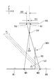
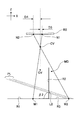
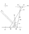
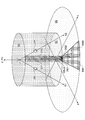
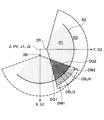
- FIG. 19A and 19B are diagrams for explaining an example of a procedure for determining a range of values that the radius of the space model MD can take.
- FIG. 19A is a plan view of the excavator 60 as viewed from above
- FIG. 19B is a side view of the excavator 60 as viewed from the side.
- 19A and 19B show that the optical axis G1 of the rear camera 2B and the optical axis G2 of the right-side camera 2R intersect with the road surface and intersect at a point J1 on the cylindrical center axis of the space model MD.
- the rear camera 2B and the right-side camera 2R are attached to the vehicle body obliquely downward so as not to protrude from the vehicle body of the excavator 60 and to capture a road surface in the vicinity of the vehicle body, including a part of the vehicle body. Take an image.
- Each of the rear camera 2B and the right side camera 2R has an imaging range indicated by hatching as shown in FIG. 19A.
- the oblique hatching with coarse eyes corresponds to the imaging range of the rear camera 2B
- the oblique hatching with fine eyes corresponds to the imaging range of the right camera 2R.
- each of the imaging ranges has a region that cannot be captured because it is hidden by the shadow of the body of the excavator 60.
- this area is filled with black
- the area DS1 corresponds to the rear camera 2R
- the area DS2 corresponds to the right camera 2R.
- the areas DS1 and DS2 are displayed in warning colors (for example, black) so that the operator can recognize that they are areas that cannot be captured by the shadow of the body of the excavator 60. It may be filled.
- each of the regions DS1 and DS2 includes a range that can be imaged without being hidden by the shadow of the vehicle body and a range that cannot be imaged by being hidden by the shadow of the vehicle body at a predetermined distance from the excavator 60. This is set by drawing boundary lines BL1 and BL2 separating the two on the road surface.
- the predetermined distance is a distance determined by the respective installation positions of the rear camera 2R and the right side camera 2R.
- the boundary lines BL1 and BL2 intersect at an intersection point PT1 in an imaging range overlapping region (a region where two types of hatched hatching overlap).
- the distance between the intersection point PT1 and the central axis of the cylinder is adopted as the minimum value that can be taken by the radius of the space model MD.
- This is a curved surface area as a projection target that can prevent the disappearance of the image of the worker existing around the excavator 60 (including a state in which only a slight road surface image disappears).
- a curved surface region R2min region indicated by a one-dot chain line circle) having the smallest radius among the curved surface regions R2 is given.
- the person PSN is a cylindrical virtual object used to derive the maximum value that the radius of the space model MD can take.
- the person PSN has a predetermined size (for example, the outer diameter when viewed from above is 600 mm), and is outside the intersection point PT1 in the imaging range overlapping region (outside in the radial direction when viewed from the center axis of the cylinder). Is placed adjacent to.
- each of the rear camera 2B and the right camera 2R draws auxiliary lines EL1 and EL2 that pass through the respective optical centers and are tangents to the circle indicated by the person PSN.
- auxiliary lines EL1 and EL2 intersect at an intersection point PT2 in the imaging range overlapping region.
- the distance between the intersection point PT2 and the central axis of the cylinder is adopted as the maximum value that can be taken by the radius of the space model MD.
- a curved surface region R2max (two points) having a largest radius among the curved surface regions R2 of the space model MD is a curved surface region as a projection target that can prevent the disappearance of the image of the worker existing around the excavator 60.
- the region indicated by the chain circle ).
- the curved surface region R2 of the space model MD that is actually adopted is set larger than the curved surface region R2min and smaller than the curved surface region R2max.
- the image of the worker around the excavator 60 in which the most easily lost condition is simulated using the person PSN shown in FIGS. 19A and 19B is at least a part of the body (typically Is divided into two parts and projected onto the curved surface region R2. Therefore, complete disappearance of the image of the person PSN can be avoided.
- the image generating apparatus 100 increases the radius of the space model MD to increase the area displayed as a road surface image, and makes the distance between the object in the traveling direction of the excavator 60 and the excavator 60 easier to understand. It is preferable to display an image.
- the image generation device 100 displays an output image that can reduce the radius of the space model MD and prevent the disappearance of the object around the excavator 60 in the imaging range overlapping region.
- the image generating apparatus 100 divides an object around the excavator 60 in the imaging range overlapping region into two and displays it in a double manner.
- the image generation apparatus 100 outputs an output image (hereinafter referred to as “traveling output image”) displayed when the excavator 60 is traveled. And an output image displayed when the excavator 60 is turned (hereinafter referred to as “turning output image”) may be selected and displayed by the driver.
- traveling output image an output image displayed when the excavator 60 is turned
- turning output image an output image displayed when the excavator 60 is turned
- the traveling output image is automatically switched to the turning output image. Also good.
- the image generating apparatus 100 can generate an output image that is suitable for the operation of the shovel 60 and has no sense of incongruity by determining the radius of the space model MD according to the operation state of the shovel 60.
- the image generation apparatus 100 determines whether an object exists in the overlapping imaging range area based on the output of an object detection sensor (for example, a laser radar sensor, an ultrasonic sensor, etc.) attached to the corner portion of the upper swing body 63. Determine whether or not.
- an object detection sensor for example, a laser radar sensor, an ultrasonic sensor, etc.
- the image generation apparatus 100 may detect the distance to the object existing in the imaging range overlapping region and determine the radius of the spatial model MD according to the determination result or the detection result.
- the image generation apparatus 100 may adopt the distance to the nearest object existing in the imaging range overlapping region as the radius of the spatial model MD.
- the image generation apparatus 100 is an object that exists in the imaging range overlapping region, and the distance between the object and the central axis of the cylinder is determined according to a predetermined value (camera installation position (for example, installation height)).
- the distance to the nearest object that is greater than or equal to the above may be adopted as the radius of the space model MD. This is because an image of an object whose distance is less than a predetermined value is treated as a road surface pattern and is not lost.
- FIG. 20 is a diagram illustrating a display example of the processing target image, similar to FIG. In FIG. 29, the arrangement of the camera 2, the arrangement of the space model MD, and the arrangement of the objects OBJ3 and OBJ4 are the same as the example shown in FIG.
- the image generation apparatus 100 can distinguish an image portion in one region DW1 on the processing target image plane R3, which is associated with an image portion corresponding to the imaging range overlapping region captured by the rear camera 2B, from other image portions. To highlight.
- the image generating apparatus 100 does not perform highlighting on the image portion in the one region DW2 on the processing target image plane R3 that is associated with the image portion corresponding to the imaging range overlapping region captured by the right camera 2R. .
- the objects OBJ3-1 and OBJ3-2 appearing in the areas DW1 and DW2 do not indicate that there are actually two objects, but one object OBJ3 is displayed in two divided into two. Only. For this reason, the image generating apparatus 100 can make the driver recognize that the region corresponds to the imaging range overlapping region by highlighting only one of the regions DW1 and DW2. Furthermore, the image generating apparatus 100 can allow the driver to recognize that both the object OBJ3-1 appearing in the area DW1 and the object OBJ3-2 appearing in the area DW2 originate from one object OBJ3. The same applies to the objects OBJ4-1 and OBJ4-2.
- the image generation apparatus 100 may highlight the image portions in both the regions DW1 and DW2 on the processing target image plane R3.
- the image generation apparatus 100 may highlight the area by increasing or decreasing the luminance of both or one of the areas DW1 and DW2 on the processing target image plane R3, for example.
- the image generation apparatus 100 may highlight the area by making a color image of both or one of the areas DW1 and DW2 on the processing target image plane R3 into a monochrome image (grayscale).
- the image generating apparatus 100 can distinguish between the image part in the one area DW1 on the processing target image plane R3, the image part in the one area DW2 on the processing target image plane R3, and the other image parts. You may make it display.
- the image portion in one region DW1 on the processing target image plane R3 is a portion associated with the image portion corresponding to the imaging range overlapping region captured by the rear camera 2B.
- the image portion in one region DW2 on the processing target image plane R3 is a portion associated with the image portion corresponding to the imaging range overlapping region captured by the right side camera 2R.
- the image generation apparatus 100 generates a processing target image based on the positional relationship between the imaging range of the camera 2 (right side camera 2R, rear camera 2B) and the space model MD shown in FIGS. 16A to 20. This is what you get. However, the same effect can be obtained even when the image generation apparatus 100 does not generate the processing target image (when the processing target image plane R3 does not exist). In this case, the processing target images in FIGS. 16C, 17, 18, and 20 are read as output images generated using the images projected on the space model MD.
- the image generation apparatus 100 employs a cylindrical spatial model MD as a spatial model, but the image generation apparatus 100 employs a spatial model having another columnar shape such as a polygonal column. Alternatively, a spatial model composed of two surfaces of a bottom surface and a side surface may be adopted. Alternatively, the image generation apparatus 100 may adopt a space model having only side surfaces.
- the image generating apparatus 100 described above is mounted with a camera on a self-propelled construction machine having movable members such as a bucket, an arm, a boom, and a turning mechanism, and moves the construction machine while presenting a surrounding image to the driver. It is incorporated in an operation support system that supports the operation of these movable members. However, the image generation apparatus 100 is mounted together with a camera on another machine (operated body) that has a movable member but does not self-propel like an industrial machine or a fixed crane, and supports operations of the machine. It may be incorporated into a support system.
- the present invention can be applied to an image generation apparatus that generates an output image based on a plurality of input images and an operation support system using the apparatus.
Abstract
Description

また、ベクトルAとベクトルBとが張る面の法線の単位ベクトルNは、ベクトルAとベクトルBとの外積から以下のように表される。

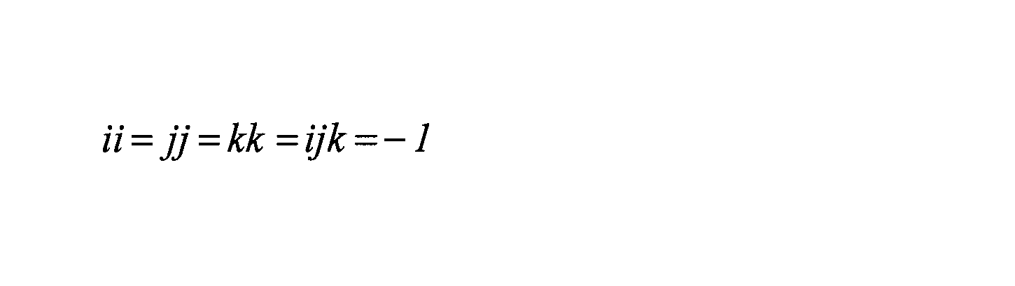

2 カメラ
2R 右側方カメラ
2B 後方カメラ
3 入力部
4 記憶部
5 表示部
10 座標対応付け部
11 出力画像生成部
40 入力画像・空間モデル対応マップ
41 空間モデル・処理対象画像対応マップ
42 処理対象画像・出力画像対応マップ
60 ショベル
61 下部走行体
62 旋回機構
63 上部旋回体
64 キャブ
Claims (8)
- 被操作体に取り付けられた複数の撮像部が撮像した複数の入力画像に基づいて出力画像を生成する画像生成装置であって、
前記被操作体を取り囲むように配置される空間モデルであり、中心軸と側面とを有する柱状の空間モデルにおける座標と、前記複数の入力画像のそれぞれが位置する複数の入力画像平面のそれぞれにおける座標とを対応付ける座標対応付け部と、
前記柱状の空間モデルにおける座標を介して、前記複数の入力画像平面のそれぞれにおける座標の値と前記出力画像が位置する出力画像平面における座標の値とを対応付けて前記出力画像を生成する出力画像生成部と、を備え、
前記柱状の空間モデルの中心軸と側面との間の距離は、前記撮像部の設置位置に応じて決定されることを特徴とする画像生成装置。 - 請求項1記載の画像生成装置であって、
前記被操作体は、走行及び旋回が可能な機械であり、
前記柱状の空間モデルの中心軸と側面との間の距離は、走行のときよりも旋回のときのほうが小さくなるように設定されることを特徴とする画像生成装置。 - 請求項1記載の画像生成装置であって、
前記複数の撮像部のうちの二つのそれぞれの撮像範囲が重複する領域に対応する前記複数の撮像部のうちの二つのそれぞれの入力画像部分は、他の入力画像部分と区別可能に表示されることを特徴とする画像生成装置。 - 請求項1記載の画像生成装置であって、
前記複数の撮像手段のうちの二つのそれぞれの撮像範囲が重複する領域に対応する前記複数の撮像手段のうちの二つのそれぞれの入力画像部分のうちの一方は、該入力画像部分のうちの他方、及び他の入力画像部分と区別可能に表示されることを特徴とする画像生成装置。 - 請求項1記載の画像生成装置であって、
前記座標対応付け部は、画像変換処理の対象となる処理対象画像が位置する処理対象画像平面における座標と、前記柱状の空間モデルにおける座標とを対応付け、
前記出力画像生成部は、前記処理対象画像平面における座標と前記柱状の空間モデルにおける座標とを介して、前記入力画像平面における座標の値と前記出力画像平面における座標の値とを対応付けて前記出力画像を生成する、
ことを特徴とする画像生成装置。 - 請求項1記載の画像生成装置であって、
前記座標対応付け部による対応付けにより得られた対応関係情報をマップ情報として格納する記憶部を更に有することを特徴とする画像生成装置。 - 被操作体の移動又は操作を支援する操作支援システムであって、
請求項1記載の画像生成装置と、
該画像生成装置が生成する出力画像を表示する表示部と
を備えることを特徴とする操作支援システム。 - 請求項7記載の操作支援システムであって、
前記表示部は、前記被操作体を移動させ或いは操作するための操作室に設置されることを特徴とする操作支援システム。
Priority Applications (4)
| Application Number | Priority Date | Filing Date | Title |
|---|---|---|---|
| KR1020127029553A KR101475583B1 (ko) | 2010-04-12 | 2011-04-08 | 화상생성장치 및 조작지원 시스템 |
| CN201180013445.8A CN102792334B (zh) | 2010-04-12 | 2011-04-08 | 图像生成装置及操作支持系统 |
| EP11768797.0A EP2560140B1 (en) | 2010-04-12 | 2011-04-08 | Image generation device and operation support system |
| US13/649,369 US8593454B2 (en) | 2010-04-12 | 2012-10-11 | Image generation device and operation support system |
Applications Claiming Priority (2)
| Application Number | Priority Date | Filing Date | Title |
|---|---|---|---|
| JP2010-091657 | 2010-04-12 | ||
| JP2010091657A JP5550970B2 (ja) | 2010-04-12 | 2010-04-12 | 画像生成装置及び操作支援システム |
Related Child Applications (1)
| Application Number | Title | Priority Date | Filing Date |
|---|---|---|---|
| US13/649,369 Continuation US8593454B2 (en) | 2010-04-12 | 2012-10-11 | Image generation device and operation support system |
Publications (1)
| Publication Number | Publication Date |
|---|---|
| WO2011129276A1 true WO2011129276A1 (ja) | 2011-10-20 |
Family
ID=44798652
Family Applications (1)
| Application Number | Title | Priority Date | Filing Date |
|---|---|---|---|
| PCT/JP2011/058898 WO2011129276A1 (ja) | 2010-04-12 | 2011-04-08 | 画像生成装置及び操作支援システム |
Country Status (6)
| Country | Link |
|---|---|
| US (1) | US8593454B2 (ja) |
| EP (1) | EP2560140B1 (ja) |
| JP (1) | JP5550970B2 (ja) |
| KR (1) | KR101475583B1 (ja) |
| CN (1) | CN102792334B (ja) |
| WO (1) | WO2011129276A1 (ja) |
Cited By (2)
| Publication number | Priority date | Publication date | Assignee | Title |
|---|---|---|---|---|
| WO2014174884A1 (ja) * | 2013-04-24 | 2014-10-30 | 住友重機械工業株式会社 | 処理対象画像生成装置、処理対象画像生成方法、及び操作支援システム |
| JP7009327B2 (ja) | 2018-07-10 | 2022-01-25 | 住友建機株式会社 | ショベル |
Families Citing this family (32)
| Publication number | Priority date | Publication date | Assignee | Title |
|---|---|---|---|---|
| JP5668857B2 (ja) * | 2011-07-29 | 2015-02-12 | 富士通株式会社 | 画像処理装置、画像処理方法および画像処理プログラム |
| JP5805574B2 (ja) * | 2012-03-29 | 2015-11-04 | 住友建機株式会社 | 作業機械用周辺監視装置 |
| US8768583B2 (en) * | 2012-03-29 | 2014-07-01 | Harnischfeger Technologies, Inc. | Collision detection and mitigation systems and methods for a shovel |
| JP6029306B2 (ja) * | 2012-03-29 | 2016-11-24 | 住友建機株式会社 | 作業機械用周辺監視装置 |
| JP5960007B2 (ja) * | 2012-09-20 | 2016-08-02 | 住友建機株式会社 | 作業機械用周辺監視装置 |
| DE102012223588A1 (de) * | 2012-12-18 | 2014-06-18 | Robert Bosch Gmbh | Vorrichtung zur erweiterten Darstellung eines Umgebungsbereichs eines Fahrzeugs |
| KR102003562B1 (ko) * | 2012-12-24 | 2019-07-24 | 두산인프라코어 주식회사 | 건설기계의 감지 장치 및 방법 |
| JP6545430B2 (ja) * | 2013-03-19 | 2019-07-17 | 住友重機械工業株式会社 | ショベル |
| JP6169381B2 (ja) * | 2013-03-19 | 2017-07-26 | 住友重機械工業株式会社 | ショベル |
| JP6302622B2 (ja) * | 2013-03-19 | 2018-03-28 | 住友重機械工業株式会社 | 作業機械用周辺監視装置 |
| JP6324665B2 (ja) * | 2013-05-16 | 2018-05-16 | 住友建機株式会社 | 作業機械用周辺監視装置 |
| JP6386213B2 (ja) * | 2013-05-16 | 2018-09-05 | 住友建機株式会社 | ショベル |
| JP6355298B2 (ja) * | 2013-05-30 | 2018-07-11 | 住友重機械工業株式会社 | 画像生成装置及びショベル |
| JP6396022B2 (ja) * | 2014-01-21 | 2018-09-26 | 住友重機械工業株式会社 | 出力画像を生成する装置 |
| JP6165085B2 (ja) * | 2014-03-07 | 2017-07-19 | 日立建機株式会社 | 作業機械の周辺監視装置 |
| DE102014204303A1 (de) * | 2014-03-10 | 2015-09-10 | Robert Bosch Gmbh | Verfahren zum Zusammenfügen von Einzelbildern, die von einem Kamerasystem aus unterschiedlichen Positionen aufgenommen wurden, zu einem gemeinsamen Bild |
| KR102426631B1 (ko) * | 2015-03-16 | 2022-07-28 | 현대두산인프라코어 주식회사 | 건설 기계의 사각 영역 표시 방법 및 이를 수행하기 위한 장치 |
| US10262466B2 (en) * | 2015-10-14 | 2019-04-16 | Qualcomm Incorporated | Systems and methods for adjusting a combined image visualization based on depth information |
| WO2017216945A1 (ja) * | 2016-06-17 | 2017-12-21 | 株式会社前田製作所 | 移動式クレーン |
| JP2018050119A (ja) * | 2016-09-20 | 2018-03-29 | 国立大学法人 東京大学 | 作業車両の表示システム |
| JP6896401B2 (ja) * | 2016-11-25 | 2021-06-30 | 東芝テック株式会社 | 物品認識装置 |
| DE102017120613B4 (de) | 2017-09-07 | 2024-03-14 | Liebherr-Werk Ehingen Gmbh | Verfahren zum Bewegen einer Last mit einem Kran |
| JP7232437B2 (ja) * | 2018-02-19 | 2023-03-03 | 国立大学法人 東京大学 | 作業車両の表示システム及び生成方法 |
| EP3588211A1 (de) * | 2018-06-27 | 2020-01-01 | Siemens Aktiengesellschaft | Steuereinrichtung zum steuern eines technischen systems und verfahren zum konfigurieren der steuereinrichtung |
| JP7296340B2 (ja) * | 2018-08-07 | 2023-06-22 | 住友建機株式会社 | ショベル |
| WO2020068960A1 (en) * | 2018-09-26 | 2020-04-02 | Coherent Logix, Inc. | Any world view generation |
| EP3651119A1 (en) * | 2018-11-06 | 2020-05-13 | Koninklijke Philips N.V. | Disparity estimation from a wide angle image |
| JP7130547B2 (ja) * | 2018-12-26 | 2022-09-05 | 住友建機株式会社 | ショベル及びショベル用周辺監視装置 |
| WO2020166455A1 (ja) * | 2019-02-14 | 2020-08-20 | 株式会社タダノ | クレーン及び経路生成システム |
| JP7255454B2 (ja) * | 2019-11-07 | 2023-04-11 | コベルコ建機株式会社 | 作業機械の周囲監視装置 |
| JP7237882B2 (ja) * | 2020-04-07 | 2023-03-13 | 住友建機株式会社 | ショベル |
| CN114020192B (zh) * | 2021-09-18 | 2024-04-02 | 特斯联科技集团有限公司 | 一种基于曲面电容实现非金属平面的互动方法和系统 |
Citations (7)
| Publication number | Priority date | Publication date | Assignee | Title |
|---|---|---|---|---|
| JP2002083285A (ja) * | 2000-07-07 | 2002-03-22 | Matsushita Electric Ind Co Ltd | 画像合成装置および画像合成方法 |
| JP3286306B2 (ja) | 1998-07-31 | 2002-05-27 | 松下電器産業株式会社 | 画像生成装置、画像生成方法 |
| JP2003204547A (ja) * | 2001-10-15 | 2003-07-18 | Matsushita Electric Ind Co Ltd | 車両周囲監視装置およびその調整方法 |
| JP2004021307A (ja) * | 2002-06-12 | 2004-01-22 | Matsushita Electric Ind Co Ltd | 運転支援装置 |
| JP2007041791A (ja) * | 2005-08-02 | 2007-02-15 | Nissan Motor Co Ltd | 俯瞰画像表示システム及び俯瞰画像の表示方法 |
| JP2008312004A (ja) * | 2007-06-15 | 2008-12-25 | Sanyo Electric Co Ltd | カメラシステム及び機械装置 |
| JP2010091657A (ja) | 2008-10-06 | 2010-04-22 | Ricoh Co Ltd | クリーニング装置、プロセスユニット及び画像形成装置 |
Family Cites Families (12)
| Publication number | Priority date | Publication date | Assignee | Title |
|---|---|---|---|---|
| JPH03286306A (ja) | 1990-04-03 | 1991-12-17 | Mitsubishi Electric Corp | 数値制御装置 |
| US7266219B2 (en) * | 2000-07-19 | 2007-09-04 | Matsushita Electric Industrial Co., Ltd. | Monitoring system |
| JP2002176641A (ja) * | 2000-12-05 | 2002-06-21 | Matsushita Electric Ind Co Ltd | 周囲映像提示装置 |
| KR100866450B1 (ko) | 2001-10-15 | 2008-10-31 | 파나소닉 주식회사 | 차량 주위 감시 장치 및 그 조정 방법 |
| JP4639753B2 (ja) * | 2004-10-25 | 2011-02-23 | 日産自動車株式会社 | 運転支援装置 |
| JP4450036B2 (ja) * | 2007-09-10 | 2010-04-14 | トヨタ自動車株式会社 | 複合画像生成装置、及びプログラム |
| JP4970296B2 (ja) * | 2008-01-21 | 2012-07-04 | 株式会社パスコ | オルソフォト画像の生成方法、および撮影装置 |
| JP5369465B2 (ja) * | 2008-03-25 | 2013-12-18 | 富士通株式会社 | 車両用画像処理装置、車両用画像処理方法、車両用画像処理プログラム |
| DE102008035428B4 (de) * | 2008-07-30 | 2010-11-18 | Daimler Ag | Verfahren und Vorrichtung zur Überwachung einer Umgebung eines Fahrzeuges |
| JP5068779B2 (ja) * | 2009-02-27 | 2012-11-07 | 現代自動車株式会社 | 車両周囲俯瞰画像表示装置及び方法 |
| TW201103787A (en) * | 2009-07-31 | 2011-02-01 | Automotive Res & Testing Ct | Obstacle determination system and method utilizing bird's-eye images |
| CN101661625B (zh) * | 2009-09-22 | 2012-07-18 | 北京理工大学 | 基于一幅标准图像生成各视角下样本图像的方法 |
-
2010
- 2010-04-12 JP JP2010091657A patent/JP5550970B2/ja active Active
-
2011
- 2011-04-08 WO PCT/JP2011/058898 patent/WO2011129276A1/ja active Application Filing
- 2011-04-08 EP EP11768797.0A patent/EP2560140B1/en active Active
- 2011-04-08 KR KR1020127029553A patent/KR101475583B1/ko active IP Right Grant
- 2011-04-08 CN CN201180013445.8A patent/CN102792334B/zh active Active
-
2012
- 2012-10-11 US US13/649,369 patent/US8593454B2/en active Active
Patent Citations (7)
| Publication number | Priority date | Publication date | Assignee | Title |
|---|---|---|---|---|
| JP3286306B2 (ja) | 1998-07-31 | 2002-05-27 | 松下電器産業株式会社 | 画像生成装置、画像生成方法 |
| JP2002083285A (ja) * | 2000-07-07 | 2002-03-22 | Matsushita Electric Ind Co Ltd | 画像合成装置および画像合成方法 |
| JP2003204547A (ja) * | 2001-10-15 | 2003-07-18 | Matsushita Electric Ind Co Ltd | 車両周囲監視装置およびその調整方法 |
| JP2004021307A (ja) * | 2002-06-12 | 2004-01-22 | Matsushita Electric Ind Co Ltd | 運転支援装置 |
| JP2007041791A (ja) * | 2005-08-02 | 2007-02-15 | Nissan Motor Co Ltd | 俯瞰画像表示システム及び俯瞰画像の表示方法 |
| JP2008312004A (ja) * | 2007-06-15 | 2008-12-25 | Sanyo Electric Co Ltd | カメラシステム及び機械装置 |
| JP2010091657A (ja) | 2008-10-06 | 2010-04-22 | Ricoh Co Ltd | クリーニング装置、プロセスユニット及び画像形成装置 |
Non-Patent Citations (1)
| Title |
|---|
| See also references of EP2560140A4 |
Cited By (4)
| Publication number | Priority date | Publication date | Assignee | Title |
|---|---|---|---|---|
| WO2014174884A1 (ja) * | 2013-04-24 | 2014-10-30 | 住友重機械工業株式会社 | 処理対象画像生成装置、処理対象画像生成方法、及び操作支援システム |
| JP2014216797A (ja) * | 2013-04-24 | 2014-11-17 | 住友重機械工業株式会社 | 処理対象画像生成装置、処理対象画像生成方法、及び操作支援システム |
| US10621743B2 (en) | 2013-04-24 | 2020-04-14 | Sumitomo Heavy Industries, Ltd. | Processing-target image creating device, processing-target image creating method, and operation assisting system |
| JP7009327B2 (ja) | 2018-07-10 | 2022-01-25 | 住友建機株式会社 | ショベル |
Also Published As
| Publication number | Publication date |
|---|---|
| EP2560140A1 (en) | 2013-02-20 |
| JP2011221865A (ja) | 2011-11-04 |
| KR20130008606A (ko) | 2013-01-22 |
| US20130033494A1 (en) | 2013-02-07 |
| JP5550970B2 (ja) | 2014-07-16 |
| EP2560140B1 (en) | 2020-06-24 |
| US8593454B2 (en) | 2013-11-26 |
| KR101475583B1 (ko) | 2014-12-30 |
| EP2560140A4 (en) | 2017-03-15 |
| CN102792334B (zh) | 2015-09-23 |
| CN102792334A (zh) | 2012-11-21 |
Similar Documents
| Publication | Publication Date | Title |
|---|---|---|
| WO2011129276A1 (ja) | 画像生成装置及び操作支援システム | |
| WO2011129275A1 (ja) | 処理対象画像生成装置、処理対象画像生成方法、及び操作支援システム | |
| JP5497617B2 (ja) | 画像生成装置及び操作支援システム | |
| JP6029306B2 (ja) | 作業機械用周辺監視装置 | |
| JP5362639B2 (ja) | 画像生成装置及び操作支援システム | |
| WO2011129277A1 (ja) | 画像生成装置及び操作支援システム | |
| JP6324665B2 (ja) | 作業機械用周辺監視装置 | |
| JP5638494B2 (ja) | 画像生成方法、画像生成装置、及び操作支援システム | |
| JP6169381B2 (ja) | ショベル | |
| JP5752631B2 (ja) | 画像生成方法、画像生成装置、及び操作支援システム | |
| JP5805574B2 (ja) | 作業機械用周辺監視装置 | |
| JP6257918B2 (ja) | ショベル | |
| JP6873889B2 (ja) | ショベル及びショベルの周囲画像生成装置 | |
| JP2020127217A (ja) | ショベル | |
| JP6246185B2 (ja) | ショベル | |
| JP5808679B2 (ja) | 画像生成装置及び操作支援システム | |
| JP2014236232A (ja) | 画像生成装置及び操作支援システム | |
| JP2020002773A (ja) | ショベル及びショベルの周囲画像生成装置 | |
| JP2014123955A (ja) | ショベル |
Legal Events
| Date | Code | Title | Description |
|---|---|---|---|
| WWE | Wipo information: entry into national phase |
Ref document number: 201180013445.8 Country of ref document: CN |
|
| 121 | Ep: the epo has been informed by wipo that ep was designated in this application |
Ref document number: 11768797 Country of ref document: EP Kind code of ref document: A1 |
|
| NENP | Non-entry into the national phase |
Ref country code: DE |
|
| WWE | Wipo information: entry into national phase |
Ref document number: 2011768797 Country of ref document: EP |
|
| ENP | Entry into the national phase |
Ref document number: 20127029553 Country of ref document: KR Kind code of ref document: A |