WO2011129208A1 - ばね - Google Patents
ばね Download PDFInfo
- Publication number
- WO2011129208A1 WO2011129208A1 PCT/JP2011/058447 JP2011058447W WO2011129208A1 WO 2011129208 A1 WO2011129208 A1 WO 2011129208A1 JP 2011058447 W JP2011058447 W JP 2011058447W WO 2011129208 A1 WO2011129208 A1 WO 2011129208A1
- Authority
- WO
- WIPO (PCT)
- Prior art keywords
- spring
- cylindrical
- cylindrical portion
- main body
- section
- Prior art date
- Legal status (The legal status is an assumption and is not a legal conclusion. Google has not performed a legal analysis and makes no representation as to the accuracy of the status listed.)
- Ceased
Links
Images



Classifications
-
- F—MECHANICAL ENGINEERING; LIGHTING; HEATING; WEAPONS; BLASTING
- F16—ENGINEERING ELEMENTS AND UNITS; GENERAL MEASURES FOR PRODUCING AND MAINTAINING EFFECTIVE FUNCTIONING OF MACHINES OR INSTALLATIONS; THERMAL INSULATION IN GENERAL
- F16F—SPRINGS; SHOCK-ABSORBERS; MEANS FOR DAMPING VIBRATION
- F16F1/00—Springs
- F16F1/02—Springs made of steel or other material having low internal friction; Wound, torsion, leaf, cup, ring or the like springs, the material of the spring not being relevant
- F16F1/025—Springs made of steel or other material having low internal friction; Wound, torsion, leaf, cup, ring or the like springs, the material of the spring not being relevant characterised by having a particular shape
-
- F—MECHANICAL ENGINEERING; LIGHTING; HEATING; WEAPONS; BLASTING
- F16—ENGINEERING ELEMENTS AND UNITS; GENERAL MEASURES FOR PRODUCING AND MAINTAINING EFFECTIVE FUNCTIONING OF MACHINES OR INSTALLATIONS; THERMAL INSULATION IN GENERAL
- F16F—SPRINGS; SHOCK-ABSORBERS; MEANS FOR DAMPING VIBRATION
- F16F1/00—Springs
- F16F1/02—Springs made of steel or other material having low internal friction; Wound, torsion, leaf, cup, ring or the like springs, the material of the spring not being relevant
- F16F1/32—Belleville-type springs
Definitions
- the present invention relates to a spring that suppresses transmission of high-frequency vibration from a counterpart member, and more particularly to improvement of the shape of the spring.
- Vibration transmission suppression technology is applied to engines, motors rotating at high speeds, washing machine dewatering tanks, buildings, and the like.
- As a technique for suppressing vibration transmission it is effective to set the natural frequency of a system composed of an object and a support sufficiently lower than a predetermined frequency band.
- As a method it is conceivable to reduce the spring constant of the support part. In this case, when a coil spring or a leaf spring is used as the support part, if the spring constant is reduced, a large deflection is required to support a high load. Is required, and the spring becomes large.
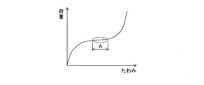
- Patent Documents 1 and 2 Since the load characteristic of the disc spring can be designed as a curve shown in FIG. 6, it is possible to set a substantially flat region A that can support a high load and set a small spring constant.
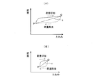
- the disc spring When the disc spring is deformed so that its shape is substantially flat when a load is applied, the inner peripheral edge and the outer peripheral edge of the disc spring slide against the mating member to generate friction. For this reason, when the use range of the disc spring is set to the range of the substantially flat region A in FIG. 6, hysteresis shown in FIG. 7A occurs in the actual load curve. As a result, the substantial dynamic spring constant in the usage range of the disc spring is an inclination of the diagonal line l connecting the point P and the point Q in FIG. In this case, when the amplitude of the use range is reduced, the slope of the diagonal line l increases as shown in FIG. 7B, and the dynamic spring constant increases.
- FIG. 8 shows the configuration of the spring 200, where FIG. 8A is a perspective view and FIG. 8B is a cross-sectional view of the right side portion of the spring 200.
- FIG. 8B shows a state where the spring 200 is installed between the first member 101 and the second member 102.
- the spring 200 includes a main body 210 having a hole 210A formed at the center.
- the main body 210 has the same shape as a disc spring and has a function as a disc spring.
- a first cylindrical portion 211 protruding toward the first member 101 is provided on the inner peripheral portion of the main body portion 210, and a second cylinder protruding toward the second member 102 is provided on the outer peripheral portion of the main body portion 210.
- a shaped portion 212 is provided.
- a first corner 213 is formed at the boundary between the main body 210 and the first cylindrical portion 211, and a second corner 214 is formed at the boundary between the main body 210 and the second cylindrical portion 212. Yes.
- the corner portions 213 and 214 can be elastically deformed so as to change the angle according to the pressing force from the counterpart members 101 and 102 when a load is applied.
- the lengths of the cylindrical portions 211 and 212 are set so that the portions on the mating members 101 and 102 side of the cylindrical portions 211 and 212 are undeformed portions.
- an object of the present invention is to provide a spring that can be set to a low height, and can accommodate a small installation space.
- the present inventor obtained knowledge that the end part can be prevented from being deformed by increasing the rigidity of the end part on the mating member side of the cylindrical part, Even when the height of the cylindrical portion is set low, it has been found that the end portion can be secured as an undeformed portion, and the present invention has been completed.
- the spring of the present invention includes a body portion having a hole, a cylindrical portion provided on at least one of the inner peripheral portion and the outer peripheral portion of the main body portion, and a boundary portion between the main body portion and the cylindrical portion.
- the cylindrical portion includes a contact portion that protrudes from the peripheral portion of the main body portion toward the mating member and abuts against the mating member, and the angle of the corner portion is applied from the mating member. It is elastically deformable so as to change according to the pressing force, and a reinforcing part that protrudes toward the inside or outside in the radial direction of the hole is formed at the contact part of the cylindrical part. Yes.
- the corner portion can be elastically deformed when a load is applied. Therefore, by appropriately setting the distance between the corner portion of the cylindrical portion and the mating member, the mating member of the cylindrical portion when the load is applied. The deformation
- the abutting portion of the cylindrical portion has a reinforcing portion that protrudes toward the inside or the outside in the radial direction of the hole portion, and thus the same effect as that of the spring 200 of the comparative example. In addition, the following effects can be obtained.
- the rigidity of the end of the cylindrical portion on the mating member side can be increased by the reinforcing portion provided at the contact portion of the cylindrical portion. Even when it is lowered, it is possible to reliably prevent the deformation of the end portion on the mating member side in the cylindrical portion when the corner portion is elastically deformed when a load is applied.
- the spring 200 of the comparative example when the height of the cylindrical portion is lowered, the proportion of the undeformed portion with respect to the entire cylindrical portion decreases accordingly.
- the rigidity of the cylindrical portion is reduced, it is easily affected by the elastic deformation of the corner portion when a load is applied, and the ratio of the non-deformed portion is substantially reduced.
- the spring of the present invention even when the height of the cylindrical portion is lowered, the rigidity of the end portion on the mating member side in the cylindrical portion is high.
- the end portion can be secured as an undeformed portion without being affected by deformation. Therefore, when the height of the cylindrical portion is lowered, the proportion of the undeformed portion relative to the entire cylindrical portion is not reduced as compared with the spring 200 of the comparative example.
- the height of the cylindrical portion can be set low, so that it can cope with a small installation space.
- the spring of the present invention can use various configurations.
- a fixing hole for fixing to the mating member can be formed in the reinforcing portion.
- occurrence of hysteresis due to sliding can be reliably prevented.
- the spring of the present invention even when the height of the cylindrical portion is lowered, the rigidity of the end portion on the mating member side in the cylindrical portion is higher by the reinforcing portion. Can be secured. As a result, since the height of the cylindrical portion can be set low, it is possible to deal with a place where the installation space is small.
- (A) is a perspective view
- (B) is a sectional side view of the spring in the state arrange
- 1 represents the operating state of the right side portion of the spring shown in FIG. 1
- (A) is a side cross-sectional view of the spring before operation (dotted line) and during operation (solid line)
- (B) is the first state during operation of the spring. It is an expanded side sectional view of a 1 corner and a 2nd corner. It is a graph showing the simulation result regarding the load characteristic at the time of changing the height of a 1st cylindrical part about the spring of the example of this invention.
- FIG. 2A is a perspective view of the spring 1, and FIG. It is.
- Spring 1 is made of, for example, spring steel or reinforcing material plastic.
- the spring 1 includes, for example, a main body 10 having a hole 10A formed at the center.
- the main body 10 extends, for example, in a direction crossing the direction of the pressing force from the first member 101 and the second member 102, and has a function as a disc spring.
- the main body 10 has, for example, a substantially conical shape that inclines as it goes downward. Thereby, the spring 1 becomes non-linear so that its load characteristic has a substantially flat region A, like the characteristic of the disc spring shown in FIG.
- the hole 10A has, for example, a circular shape.
- a first cylindrical portion 11 (cylindrical portion) that protrudes toward the first member 101 is provided on the inner peripheral portion of the main body portion 10.
- An upper end portion of the first tubular portion 11 (tubular portion) is a contact portion that contacts the first member 101.
- a second cylindrical portion 12 (cylindrical portion) that protrudes toward the second member 102 is provided on the outer peripheral portion of the main body portion 10.
- the lower end portion of the second cylindrical portion 12 is a contact portion that contacts the first member 102.
- the cylindrical parts 11 and 12 are cylindrical parts, for example.
- the abutting portion of the first cylindrical portion 11 has a reinforcing portion 21 that protrudes inward in the radial direction of the hole 10A.
- a fixing hole 21 ⁇ / b> A for fixing to the first member 101 is formed in the reinforcing portion 21.
- the contact portion of the second cylindrical portion 12 has a reinforcing portion 22 that protrudes outward in the radial direction of the hole portion 10A.
- a fixing hole 22 ⁇ / b> A for fixing to the second member 102 is formed in the reinforcing portion 22.
- the cylindrical portions 11 and 12 are fixed to the mating members 101 and 102 by providing screw means or the like in the fixing holes 21A and 22A.
- a first corner 13 is formed at the boundary between the main body 10 and the first cylindrical portion 11, and a second corner 14 is formed at the boundary between the main body 10 and the second cylindrical portion 12. Yes.
- the first corner portion 13 and the second corner portion 14 can be elastically deformed so as to change their angles according to the pressing force from the first member 101 and the second member 102.
- the spring 1 can be formed by bending each part by press molding. Moreover, each part can be formed by welding.
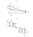
- FIG. 2 shows the operating state of one spring 1 installed between the first member 101 and the second member 102
- (A) shows the state before operation of the spring 1 (dotted line) and during operation (solid line).
- FIG. 4B is an enlarged cross-sectional view of the first corner portion 13 and the second corner portion 14 when the spring 1 operates.
- FIG. 2 only the right side portion of one spring 1 is shown in the same manner as in FIG. In FIG. 2, only the right side portion of the spring 1 is illustrated, and the reinforcing portions 21 and 22 are not illustrated.
- the main body 10 extends in a direction that intersects the direction of the pressing force from the first member 101, and on the upper side of the spring 1, the first cylindrical portion 11 extends from the inner periphery of the main body 10 to the first member 101. Projecting toward and abutting there.
- the first corner portion 13 formed at the boundary between the main body portion 10 and the first cylindrical portion 11 is elastically deformed so that the angle ⁇ changes according to the pressing force from the first member 101 when a load is applied. be able to.
- first corner portion 13 is a portion formed at the boundary portion between the main body portion 10 and the first cylindrical portion 11 having the above positional relationship, such first corner portion 13 is It is possible to move to the inside (left side in the figure) of the inner periphery of the main body 10 while changing the angle ⁇ when applying a load.
- the first corner portion 13 can be elastically deformed when a load is applied in this way, the first cylindrical portion 11 is not deformed on the first member 101 side when a load is applied (from a point S in FIG. 2B).
- the length of the first cylindrical portion 11 so as to have the upper side
- deformation of the first member 101 side portion of the first cylindrical portion 11 can be prevented.
- the second cylindrical portion 11 protrudes from the inner peripheral portion of the main body portion 10 toward the second member 102 and is in contact therewith.
- the second corner portion 14 having a function similar to that of the first corner portion 13 changes the angle ⁇ in accordance with the pressing force from the second member 102 during elastic deformation by applying a load while the main body portion 10. It is possible to move to the outer side (right side in the figure) of the outer peripheral portion.
- the second corner portion 14 can be elastically deformed when a load is applied, the second cylindrical portion 12 is not deformed on the second member 102 side when a load is applied (from a point T in FIG. 2B).
- the length of the second cylindrical portion 12 so as to have the (lower side)
- deformation of the second member 102 side portion of the second cylindrical portion 12 can be prevented.
- the spring 1 since the spring 1 has the non-deformable portions in the cylindrical portions 11 and 12, sliding between the spring 1 and the counterpart member can be prevented. As a result, in the load characteristics of the spring 1, the hysteresis that has been a problem with the disc spring does not occur.
- the contact portion of the first cylindrical portion 11 has the reinforcing portion 21 that protrudes inward in the radial direction of the hole portion 10A, and therefore the first member 101 side in the first cylindrical portion 11.
- the rigidity of the end of the can be increased. Since the contact portion of the second cylindrical portion 12 has the reinforcing portion 22 that protrudes toward the outside in the radial direction of the hole portion 10A, the end portion of the second cylindrical portion 12 on the second member 102 side.
- the rigidity of can be increased. As a result, even when the height of the cylindrical portions 11 and 12 is lowered, when the corner portions 13 and 14 are elastically deformed when a load is applied, the end portions of the counterpart members 101 and 102 in the cylindrical portions 11 and 12 are not affected. Deformation can be prevented.
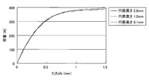
- FIG. 3 shows the springs according to the present invention (specific examples of the spring 1) in which the height of the first cylindrical portion 11 shown in FIG. 5A is set to 2.8 mm, 1.0 mm, and 0.1 mm. It is a graph showing the simulation result regarding the load characteristic in an aspect.
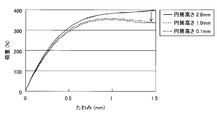
- FIG. 4 shows a simulation regarding load characteristics in each aspect in which the height of the first cylindrical portion 211 shown in FIG. 5B is set to 2.8 mm, 1.0 mm, and 0.1 mm for the spring 200 of the comparative example. It is a graph showing a result.
- the height of the first cylindrical portion 11 of the spring 1 of the present invention example is the height t of the linear portion of the first cylindrical portion 11 as shown in FIG.
- the height of the first cylindrical portion 211 was set to the height t of the linear portion of the first cylindrical portion 11 as shown in FIG.
- the first cylindrical portion 11 is provided with the reinforcing portion 21, the second cylindrical portion 12 is not provided with the reinforcing portion 22, and the reinforcing portion 21 is not formed with the fixing hole 21A (that is, The spring which closed the opening part of the 1st cylindrical part 11 was used.
- the spring of the present invention has the same configuration as the spring 200 of the comparative example, except that the reinforcing portion 21 is provided in the first cylindrical portion 11.
- a spring with a height of 2.8 mm and a spring with a height of 1.0 mm obtained substantially the same load characteristics.
- the generated load was significantly reduced and hysteresis was generated.
- the rigidity of the first cylindrical portion is low in the spring of the comparative example, and the non-deformed portion is not secured.
- the first cylindrical portion has a height of 2.8 mm, a spring of 1.0 mm, and a spring of 0.1 mm.
- the load was almost the same, and hysteresis was not generated, and a substantially equivalent load characteristic was obtained.
- the reason is that, in the spring of the present invention, the rigidity of the end portion on the mating member side in the first cylindrical portion is higher by the reinforcing portion, so even if the height of the cylindrical portion is lowered, the end This is considered to be because the part was secured as an indeformable part.
- the reinforcing portions 21 and 22 provided at the contact portions of the cylindrical portions 11 and 12 have high rigidity at the ends of the cylindrical portions 11 and 12 on the mating member 101 and 102 side. Therefore, even when the heights of the cylindrical portions 11 and 12 are lowered, the end portions thereof can be ensured as undeformed portions. Therefore, since the height of the cylindrical parts 11 and 12 can be set low, it can respond to a location with a small installation space.
- the main body of the present invention can have, for example, a conical shape, an S shape, a step shape, or a flat shape that is inclined downward from the outer peripheral portion toward the inner peripheral portion.
- the cylindrical portion may be cylindrical, and the cross-sectional shape thereof may be a polygon, and the side cross-sectional shape thereof may be a curved shape.
- a slit can be formed in the main body part 10 and the cylindrical parts 11 and 12 for weight reduction.
- first cylindrical portion 11 is protruded toward the first member 101 and brought into contact therewith, and the second cylindrical portion 12 is brought into contact with the second member 102.
- the shape portion 11 may be protruded toward the second member 102 and brought into contact therewith, and the second tubular portion 12 may be protruded toward the first member 11 and brought into contact therewith.
- the shapes of the first corner portion 13 and the second corner portion 14 are not limited to the illustrated shapes, and can be changed to various shapes such as a curved surface shape.
- the 1st cylindrical part 11 and the 2nd cylindrical part 12 were formed in the inner peripheral part and outer peripheral part of the main-body part 10, it is only in any one of the 1st cylindrical part 11 and the 2nd cylindrical part 12. It may be formed.
- the reinforcing parts 21 and 22 may be fixed to the mating members 101 and 102 by welding.
- the protruding directions of the reinforcing parts 21 and 22 can be variously modified.
- the reinforcing part 21 protrudes outward in the radial direction of the hole 10A, and the reinforcing part 22 is inward of the radial direction of the hole 10A. Can project toward.
Landscapes
- Engineering & Computer Science (AREA)
- General Engineering & Computer Science (AREA)
- Mechanical Engineering (AREA)
- Springs (AREA)
Abstract
高さを低く設定することができ、これにより設置スペースが小さな箇所に対応することができるばねを提供する。 第1筒状部11の当接部は、孔部10Aの径方向の内側に向かって突出する補強部21を有しているから、第1筒状部11における第1部材101側の端部の剛性を高くすることができる。第2筒状部12の当接部は、孔部10Aの径方向の外側に向かって突出する補強部22を有しているから、第2筒状部12における第2部材102側の端部の剛性を高くすることができる。これにより、筒状部11,12の高さを低くした場合でも、荷重印加時の角部13,14の弾性変形の際、筒状部11,12における相手部材側101,102の端部の変形を防止することができる。
Description
本発明は、相手部材からの高周波振動の伝達を抑制するばねに係り、特にばねの形状の改良に関する。
自動車産業や、精密機器産業、家電、建築等の各種分野では、振動伝達を抑制する技術が要求されている。振動伝達の抑制技術は、エンジンや、高速回転するモータ、洗濯機の脱水槽、建築物等に適用されている。振動伝達の抑制技術としては、対象物と支持部により構成される系の固有振動数を、所定の振動数帯域よりも十分に低く設定することが有効である。その手法として、支持部のばね定数を小さくすることが考えられるが、この場合、支持部としてコイルばねや板ばねを用いたとき、ばね定数を小さくすると、高荷重を支えるためには、大きな撓みが必要となり、ばねが大型化してしまう。
そこで、対象物と支持部との間に皿ばねを用いる手法が提案されている(たとえば特許文献1,2)。皿ばねの荷重特性は、図6に示す曲線のように設計することができるから、高荷重を支えることができるとともにばね定数を小さく設定することができる略平坦領域Aを設定することができる。
皿ばねは、その形状が荷重印加により略平坦状をなすように変形するときに、皿ばねの内周縁部および外周縁部が、相手部材に対して摺動して摩擦が発生する。このため、皿ばねの使用範囲を図6の略平坦領域Aの範囲に設定した場合、実際の荷重曲線には、図7(A)に示すヒステリシスが生じる。その結果、皿ばねの使用範囲での実質的な動的ばね定数は、図7(A)の点Pと点Qを結ぶ対角線lの傾きとなる。この場合、使用範囲の振幅を小さくしたとき、図7(B)に示すように、対角線lの傾きが大きくなるため、動的ばね定数が大きくなってしまう。このように皿ばねが適用された系では、高周波振動のような微振幅の振動を入力すると、皿ばねの動的ばね定数が大きくなるため、系の固有振動数が増加し、その結果、高周波振動の伝達を抑制できないという問題があった。
以上のような問題を解決するために本出願人は、図8に示すばね200を提案している(たとえば特開2009-275738)。図8は、ばね200の構成を表し、(A)は斜視図、(B)は、ばね200の右側部分の断面図である。図8(B)は、ばね200が第1部材101と第2部材102の間に設置されている状態を表している。ばね200は、中心部に孔部210Aが形成された本体部210を備えている。本体部210は、皿ばねと同様の形状をなし、皿ばねとしての機能を有する。
本体部210の内周部には、第1部材101に向けて突出する第1筒状部211が設けられ、本体部210の外周部には、第2部材102に向けて突出する第2筒状部212が設けられている。本体部210と第1筒状部211との境界部には第1角部213が形成され、本体部210と第2筒状部212との境界部には第2角部214が形成されている。
ばね200では、角部213,214が、荷重印加時に相手部材101,102からの押圧力に応じて、その角度を変化させるように弾性変形することができる。この場合、筒状部211,212の相手部材101,102側の部分は不変形部分となるように筒状部211,212の長さを設定している。これによりばね200では、筒状部211,212の相手部材101,102に対する摺動を防止することができる。その結果、ばね200の荷重特性では、ヒステリシスが発生しない。
しかしながら、ばね200では、上記のように筒状部211,212の相手部材101,102側の部分を不変形部分として確保する必要があるため、筒状部211,212の高さを低くすることに限界があった。設置スペースが小さな箇所に対応するために、より好適なばねが望まれている。
したがって、本発明は、高さを低く設定することができ、これにより設置スペースが小さな箇所に対応することができるばねを提供することを目的としている。
本発明者は、筒状部について鋭意検討を重ねた結果、筒状部の相手部材側の端部の剛性を高めることにより、その端部の変形を防止することができるとの知見を得、筒状部の高さを低く設定した場合でも、その端部を不変形部分として確保することができることを見出し、本発明の完成に至った。
本発明のばねは、孔部を有する本体部と、本体部の内周部および外周部のうちの少なくとも一方の周部に設けられた筒状部と、本体部と筒状部との境界部に形成された角部とを備え、筒状部は、本体部の周部から相手部材に向けて突出してそこに当接する当接部を備え、角部は、その角度が相手部材から加えられる押圧力に応じて変化するように弾性変形可能であり、筒状部の当接部には、孔部の径方向の内側あるいは外側に向かって突出する補強部が形成されていることを特徴としている。
本発明のばねでは、荷重印加時に角部が弾性変形することができるので、筒状部における角部と相手部材との間の距離を適宜設定することにより、荷重印加時に筒状部の相手部材近傍の部位の変形を防止することができる。したがって、筒状部の相手部材に対する摺動を防止することができるので、筒状部と相手部材との間に摩擦が発生しなく、その結果、ばねの荷重特性にヒステリシスが発生しない。
ここで本発明のばねでは、筒状部の当接部が、孔部の径方向の内側あるいは外側に向かって突出する補強部を有しているから、比較例のばね200と同様な上記効果に加えて、次のような効果を得ることができる。
すなわち、本発明のばねでは、筒状部の当接部に設けられた補強部によって、筒状部における相手部材側の端部の剛性を高くすることができるから、筒状部の高さを低くした場合でも、荷重印加時の角部の弾性変形の際、筒状部における相手部材側の端部の変形を確実に防止することができる。具体的には、比較例のばね200では、筒状部の高さを低くした場合には、それに応じて、筒状部の全体に対する不変形部分の占める割合が減少する。しかも、この場合、筒状部の剛性が低くなるため、荷重印加時の角部の弾性変形の影響を受けやすくなり、実質的に不変形部分の占める割合の減少が顕著になる。これに対して、本発明のばねでは、筒状部の高さを低くした場合でも、筒状部における相手部材側の端部の剛性が高くなっているから、荷重印加時の角部の弾性変形の影響を受けず、上記端部を不変形部分として確保することができる。したがって、筒状部の高さを低くした場合、筒状部の全体に対する不変形部分の占める割合は、比較例のばね200と比較して、小さくならない。
以上のことから本発明のばねでは、筒状部の高さを低く設定することができるので、設置スペースが小さな箇所に対応することができる。
本発明のばねは種々の構成を用いることができる。たとえば補強部には、相手部材に固定するための固定用孔部を形成することができる。この態様では、相手部材に対する摺動を確実に防止することができるから、摺動によるヒステリシスの発生を確実に防止することができる。
本発明のばねによれば、筒状部の高さを低くした場合でも、筒状部における相手部材側の端部の剛性が補強部により高くなっているから、その端部を不変形部分として確保することができる。その結果、筒状部の高さを低く設定することができるので、設置スペースが小さな箇所に対応することができる。
1…ばね、10…本体部、10A…孔部、11…第1筒状部(筒状部)、12…第2筒状部(筒状部)、13…第1角部(角部)、14…第2角部(角部)、21,22…補強部、21A,22A…固定用孔部、101…第1部材、102…第2部材
(1)実施形態の構成
(1-1)全体構成
以下、本発明の実施形態について図面を参照して説明する。図2は、ばね1の構成を表し、(A)はばね1の斜視図、(B)は、第1部材101と第2部材102との間に配置されたばね1の右側部分の側断面図である。
(1-1)全体構成
以下、本発明の実施形態について図面を参照して説明する。図2は、ばね1の構成を表し、(A)はばね1の斜視図、(B)は、第1部材101と第2部材102との間に配置されたばね1の右側部分の側断面図である。
ばね1は、たとえば、ばね鋼や強化材プラスチックからなる。ばね1は、たとえば中心部に孔部10Aが形成された本体部10を備えている。本体部10は、たとえば第1部材101と第2部材102からの押圧力の方向に対して交差する方向に延在し、皿ばねとしての機能を有する。本体部10は、たとえばたとえば下方に向かうに従って傾斜する略円錐形状をなしている。これにより、ばね1は、その荷重特性が、図6に示す皿ばねの特性と同様に、略平坦領域Aを有するように非線形となる。
孔部10Aは、たとえば円形状をなしている。本体部10の内周部には、第1部材101に向けて突出する第1筒状部11(筒状部)が設けられている。第1筒状部11(筒状部)の上端部は、第1部材101に当接する当接部である。本体部10の外周部には、第2部材102に向けて突出する第2筒状部12(筒状部)が設けられている。第2筒状部12の下端部は、第1部材102に当接する当接部である。筒状部11,12はたとえば円筒部である。
第1筒状部11の当接部は、孔部10Aの径方向の内側に向かって突出する補強部21を有している。補強部21には、第1部材101に固定するための固定用孔部21Aが形成されている。第2筒状部12の当接部は、孔部10Aの径方向の外側に向かって突出する補強部22を有している。補強部22には、たとえば第2部材102に固定するための固定用孔部22Aが形成されている。固定用孔部21A,22Aにねじ手段等を設けることにより、筒状部11,12は、相手部材101,102に固定される。
本体部10と第1筒状部11との境界部には第1角部13が形成され、本体部10と第2筒状部12との境界部には第2角部14が形成されている。第1角部13および第2角部14は、第1部材101と第2部材102からの押圧力に応じて、その角度を変化させるように弾性変形可能である。
ばね1は、プレス成形により各部位を折り曲げて形成することができる。また、各部位を溶接して形成することができる。
(1-2)筒状部の機能
荷重印加時における筒状部11,12の機能について、おもに図2を参照して説明する。図2は、第1部材101と第2部材102の間に設置された1個のばね1の動作状態を表し、(A)は、ばね1の動作前(点線)と動作時(実線)の断面図であり、(B)は、ばね1の動作時の第1角部13および第2角部14の拡大断面図である。なお、図2では、図2(B)と同様に、1個のばね1の右側部分のみを図示している。なお、図2では、ばね1の右側部分のみを図示し、補強部21,22の図示は省略している。
荷重印加時における筒状部11,12の機能について、おもに図2を参照して説明する。図2は、第1部材101と第2部材102の間に設置された1個のばね1の動作状態を表し、(A)は、ばね1の動作前(点線)と動作時(実線)の断面図であり、(B)は、ばね1の動作時の第1角部13および第2角部14の拡大断面図である。なお、図2では、図2(B)と同様に、1個のばね1の右側部分のみを図示している。なお、図2では、ばね1の右側部分のみを図示し、補強部21,22の図示は省略している。
図2(A)の点線で示すように、第1部材101と第2部材102の間に配置されたばね1に対して、第1部材101から下側方向の荷重を加える。すると、図2(B)の実線で示すように、ばね1は撓んで第1部材101が下方に移動する。図中の符号dは、ばね1のたわみの大きさを示している。
本体部10は、第1部材101からの押圧力の方向に交差する方向に延在し、ばね1の上側において、第1筒状部11は、本体部10の内周部から第1部材101に向けて突出してそこに当接している。そのような本体部10と第1筒状部11の境界部に形成した第1角部13は、荷重印加時に第1部材101からの押圧力に応じて角度αが変化するように弾性変形することができる。この場合、第1角部13は、上記のような位置関係にある本体部10と第1筒状部11の境界部に形成された部位であるから、そのような第1角部13は、荷重印加時に角度αを変化させながら、本体部10の内周部の内側(図の左側)に移動することができる。
このように荷重印加時に第1角部13は弾性変形することができるので、第1筒状部11が荷重印加時に第1部材101側の不変形部分(図2(B)中の点Sより上側)を有するように第1筒状部11の長さを適宜設定することにより、第1筒状部11の第1部材101側部分の変形を防止することができる。
一方、ばね1の下側において、第2筒状部11は、本体部10の内周部から第2部材102に向けて突出してそこに当接している。この場合、第1角部13と同様な機能を有する第2角部14は、荷重印加による弾性変形時に、第2部材102からの押圧力に応じて、角度βを変化させながら、本体部10の外周部の外部側(図の右側)に移動することができる。
このように荷重印加時に第2角部14は弾性変形することができるので、第2筒状部12が荷重印加時に第2部材102側の不変形部分(図2(B)中の点Tより下側)を有するように第2筒状部12の長さを適宜設定することにより、第2筒状部12の第2部材102側部分の変形を防止することができる。
以上のようにばね1は、筒状部11,12に不変形部分を有するので、ばね1と相手部材との摺動を防止することができる。その結果、ばね1の荷重特性では、皿ばねで問題となっていたヒステリシスが発生しない。
(2)実施形態の動作
ばね1の動作について図面を参照して説明する。ばね1では、第1角部13の弾性変形時、第1筒状部11が第1部材101側の不変形部分(図2(B)中の点Sより上側)を有するとともに、第2角部14の弾性変形時、第2筒状部12が荷重印加時に第2部材102側の不変形部分(図2(B)中の点Tより下側)を有する。
ばね1の動作について図面を参照して説明する。ばね1では、第1角部13の弾性変形時、第1筒状部11が第1部材101側の不変形部分(図2(B)中の点Sより上側)を有するとともに、第2角部14の弾性変形時、第2筒状部12が荷重印加時に第2部材102側の不変形部分(図2(B)中の点Tより下側)を有する。
ここで、第1筒状部11の当接部は、孔部10Aの径方向の内側に向かって突出する補強部21を有しているから、第1筒状部11における第1部材101側の端部の剛性を高くすることができる。第2筒状部12の当接部は、孔部10Aの径方向の外側に向かって突出する補強部22を有しているから、第2筒状部12における第2部材102側の端部の剛性を高くすることができる。これにより、筒状部11,12の高さを低くした場合でも、荷重印加時の角部13,14の弾性変形の際、筒状部11,12における相手部材側101,102の端部の変形を防止することができる。
図3は、本発明例のばね(ばね1の具体例)について、図5(A)に示す第1筒状部11の高さを2.8mm、1.0mm、0.1mmに設定した各態様での荷重特性に関するシミュレーション結果を表すグラフである。図4は、比較例のばね200について、図5(B)に示す第1筒状部211の高さを2.8mm、1.0mm、0.1mmに設定した各態様での荷重特性に関するシミュレーション結果を表すグラフである。なお、本発明例のばね1の第1筒状部11の高さは、図5(A)に示すように第1筒状部11の直線状部の高さtとし、比較例のばね200の第1筒状部211の高さは、図5(B)に示すように第1筒状部11の直線状部の高さtとした。
本発明例のばねでは、第1筒状部11に補強部21を設け、第2筒状部12に補強部22を設けず、補強部21には固定用孔部21Aを形成しない(すなわち、第1筒状部11の開口部を閉塞した)ばねを用いた。本発明例のばねは、第1筒状部11に補強部21に設けた以外は、比較例のばね200と同様の構成とした。すなわち、本発明例のばねおよび比較例のばね200について、材質、板厚(=0.4mm)、本体部の高さ(=3.17mm)、本体部の内径(=13mm、第1筒状部の開口部の径)、本体部の外径(=47mm、第2筒状部の開口部の径)、および、第2筒状部の高さ(=5.2mm)は同じものとした。
図4から判るように、比較例では、第1筒状部の高さが2.8mmのばねと1.0mmのばねは略同等な荷重特性が得られたが、第1筒状部の高さが0.1mmのばねの荷重特性では、発生荷重が大幅に減少するとともに、ヒステリシスが発生した。その理由としては、比較例のばねでは、第1筒状部の剛性が低くなり、不変形部分が確保されなかったためであると考えられる。これに対して、図3から判るように、本発明例のばねでは、第1筒状部の高さが2.8mmのばね、1.0mmのばね、0.1mmのばねの全てについて、発生荷重が略同等で、かつヒステリシスが発生しなく、略同等な荷重特性が得られた。その理由としては、本発明例のばねでは、第1筒状部における相手部材側の端部の剛性が補強部により高くなっているから、筒状部の高さを低くした場合でも、その端部が不変形部分として確保されていたからであると考えられる。
以上のように本実施形態では、筒状部11,12の当接部に設けられた補強部21,22によって、筒状部11,12における相手部材101,102側の端部の剛性が高くなっているから、筒状部11,12の高さを低くした場合でも、その端部を不変形部分として確保することができる。したがって、筒状部11,12の高さを低く設定することができるので、設置スペースが小さな箇所に対応することができる。
(3)変形例
以上のように上記実施形態を挙げて本発明を説明したが、本発明は上記実施形態に限定されるものではなく、種々の変形が可能である。なお、以下の変形例では、上記実施形態と同様な構成要素には同符号を付し、その説明は省略している。
以上のように上記実施形態を挙げて本発明を説明したが、本発明は上記実施形態に限定されるものではなく、種々の変形が可能である。なお、以下の変形例では、上記実施形態と同様な構成要素には同符号を付し、その説明は省略している。
本発明の本体部は、たとえば、外周部から内周部に向かって下方に傾斜する円錐状、S字状や、階段状、平坦状をなすことができる。筒状部は、筒状であればよく、その断面形状は多角形でもよく、その側断面形状は、曲線状でもよい。また、本体部10および筒状部11,12には、軽量化のためにスリットを形成することができる。
上記実施形態では、第1筒状部11を第1部材101に向けて突出させてそこに当接させ、かつ第2筒状部12を第2部材102に当接させたが、第1筒状部11を第2部材102向けて突出させてそこに当接させ、第2筒状部12を第1部材11に向けて突出させてそこに当接させてもよい。さらに、第1角部13および第2角部14の形状は、図示の形状に限定されるものではなく、曲面形状等の種々の形状に変更可能である。
また、第1筒状部11および第2筒状部12を本体部10の内周部および外周部に形成したが、第1筒状部11および第2筒状部12のいずれか一方のみに形成してもよい。さらに、固定用孔部21A,22Aを設けてねじ手段等により固定する代わりに、溶接によって補強部21,22を相手部材101,102に固定してもよい。補強部21,22の突出方向は、種々の変形が可能であり、たとえば補強部21は、孔部10Aの径方向の外側に向かって突出し、補強部22は、孔部10Aの径方向の内側に向かって突出することができる。
Claims (3)
- 孔部を有する本体部と、
前記本体部の内周部および外周部のうちの少なくとも一方の周部に設けられた筒状部と、
前記本体部と前記筒状部との境界部に形成された角部とを備え、
前記筒状部は、前記本体部の前記周部から相手部材に向けて突出してそこに当接する当接部を備え、
前記角部は、その角度が前記相手部材から加えられる押圧力に応じて変化するように弾性変形可能であり、
前記筒状部の前記当接部には、前記孔部の径方向の内側あるいは外側に向かって突出する補強部が形成されていることを特徴とするばね。 - 前記当接部は、前記押圧力が変化しても、前記相手部材に対して摺動しないことを特徴とする請求項1に記載のばね。
- 前記補強部には、前記相手部材に固定するための固定用孔部が形成されていることを特徴とする請求項1または2に記載のばね。
Applications Claiming Priority (2)
| Application Number | Priority Date | Filing Date | Title |
|---|---|---|---|
| JP2010092042A JP2011220477A (ja) | 2010-04-13 | 2010-04-13 | ばね |
| JP2010-092042 | 2010-04-13 |
Publications (1)
| Publication Number | Publication Date |
|---|---|
| WO2011129208A1 true WO2011129208A1 (ja) | 2011-10-20 |
Family
ID=44798586
Family Applications (1)
| Application Number | Title | Priority Date | Filing Date |
|---|---|---|---|
| PCT/JP2011/058447 Ceased WO2011129208A1 (ja) | 2010-04-13 | 2011-04-01 | ばね |
Country Status (2)
| Country | Link |
|---|---|
| JP (1) | JP2011220477A (ja) |
| WO (1) | WO2011129208A1 (ja) |
Families Citing this family (1)
| Publication number | Priority date | Publication date | Assignee | Title |
|---|---|---|---|---|
| JP6049184B2 (ja) | 2012-12-04 | 2016-12-21 | Kyb株式会社 | 制御バルブ |
Citations (5)
| Publication number | Priority date | Publication date | Assignee | Title |
|---|---|---|---|---|
| JPS5988553U (ja) * | 1982-12-06 | 1984-06-15 | 三木プ−リ株式会社 | 無段変速プ−リ |
| JP2009519419A (ja) * | 2005-12-14 | 2009-05-14 | ルノー・エス・アー・エス | 剛性が可変なスプリング用支持要素 |
| WO2009139332A1 (ja) * | 2008-05-13 | 2009-11-19 | 日本発條株式会社 | ばね |
| JP2010071121A (ja) * | 2008-09-17 | 2010-04-02 | Kubota Corp | エンジンの軸受装置 |
| JP2010255757A (ja) * | 2009-04-24 | 2010-11-11 | Optnics Precision Co Ltd | 面状ばね及びこれを用いた安全弁 |
-
2010
- 2010-04-13 JP JP2010092042A patent/JP2011220477A/ja active Pending
-
2011
- 2011-04-01 WO PCT/JP2011/058447 patent/WO2011129208A1/ja not_active Ceased
Patent Citations (5)
| Publication number | Priority date | Publication date | Assignee | Title |
|---|---|---|---|---|
| JPS5988553U (ja) * | 1982-12-06 | 1984-06-15 | 三木プ−リ株式会社 | 無段変速プ−リ |
| JP2009519419A (ja) * | 2005-12-14 | 2009-05-14 | ルノー・エス・アー・エス | 剛性が可変なスプリング用支持要素 |
| WO2009139332A1 (ja) * | 2008-05-13 | 2009-11-19 | 日本発條株式会社 | ばね |
| JP2010071121A (ja) * | 2008-09-17 | 2010-04-02 | Kubota Corp | エンジンの軸受装置 |
| JP2010255757A (ja) * | 2009-04-24 | 2010-11-11 | Optnics Precision Co Ltd | 面状ばね及びこれを用いた安全弁 |
Also Published As
| Publication number | Publication date |
|---|---|
| JP2011220477A (ja) | 2011-11-04 |
Similar Documents
| Publication | Publication Date | Title |
|---|---|---|
| JP4815469B2 (ja) | ばね | |
| JP6042411B2 (ja) | 皿ばね | |
| JP5073643B2 (ja) | ばね | |
| KR20090096644A (ko) | 코일 스프링 | |
| WO2011148850A1 (ja) | サスペンション装置 | |
| JP6113573B2 (ja) | センターベアリングサポート | |
| WO2011129208A1 (ja) | ばね | |
| JP2011220476A (ja) | ばね | |
| WO2011158622A1 (ja) | ばね | |
| JP5281927B2 (ja) | ばねの積層構造 | |
| JP4742122B2 (ja) | 防振装置 | |
| JP5016725B2 (ja) | ばね | |
| KR20110023626A (ko) | 축 방향 체결 하중을 부여하는 스냅링 | |
| JP2018179147A (ja) | ストッパ | |
| JP2011052647A (ja) | 電気冷蔵庫 | |
| JP6934389B2 (ja) | バネ組立体 | |
| JP4751423B2 (ja) | ばねの積層機構 | |
| JP5819253B2 (ja) | 皿ばね | |
| JP5394904B2 (ja) | ばね | |
| KR102251340B1 (ko) | 이음방지장치 | |
| JP2020197295A (ja) | バネ組立体 | |
| JP2010166364A (ja) | スピーカおよびスピーカ用支持体 |
Legal Events
| Date | Code | Title | Description |
|---|---|---|---|
| 121 | Ep: the epo has been informed by wipo that ep was designated in this application |
Ref document number: 11768729 Country of ref document: EP Kind code of ref document: A1 |
|
| NENP | Non-entry into the national phase |
Ref country code: DE |
|
| 122 | Ep: pct application non-entry in european phase |
Ref document number: 11768729 Country of ref document: EP Kind code of ref document: A1 |