WO2011125598A1 - 物品保持装置 - Google Patents
物品保持装置 Download PDFInfo
- Publication number
- WO2011125598A1 WO2011125598A1 PCT/JP2011/057583 JP2011057583W WO2011125598A1 WO 2011125598 A1 WO2011125598 A1 WO 2011125598A1 JP 2011057583 W JP2011057583 W JP 2011057583W WO 2011125598 A1 WO2011125598 A1 WO 2011125598A1
- Authority
- WO
- WIPO (PCT)
- Prior art keywords
- article
- belt
- main body
- holding device
- bobbin
- Prior art date
- Legal status (The legal status is an assumption and is not a legal conclusion. Google has not performed a legal analysis and makes no representation as to the accuracy of the status listed.)
- Ceased
Links
Images








Classifications
-
- B—PERFORMING OPERATIONS; TRANSPORTING
- B62—LAND VEHICLES FOR TRAVELLING OTHERWISE THAN ON RAILS
- B62J—CYCLE SADDLES OR SEATS; AUXILIARY DEVICES OR ACCESSORIES SPECIALLY ADAPTED TO CYCLES AND NOT OTHERWISE PROVIDED FOR, e.g. ARTICLE CARRIERS OR CYCLE PROTECTORS
- B62J7/00—Luggage carriers
- B62J7/08—Equipment for securing luggage on carriers
-
- B—PERFORMING OPERATIONS; TRANSPORTING
- B62—LAND VEHICLES FOR TRAVELLING OTHERWISE THAN ON RAILS
- B62J—CYCLE SADDLES OR SEATS; AUXILIARY DEVICES OR ACCESSORIES SPECIALLY ADAPTED TO CYCLES AND NOT OTHERWISE PROVIDED FOR, e.g. ARTICLE CARRIERS OR CYCLE PROTECTORS
- B62J11/00—Supporting arrangements specially adapted for fastening specific devices to cycles, e.g. supports for attaching maps
- B62J11/26—Supporting arrangements specially adapted for fastening specific devices to cycles, e.g. supports for attaching maps specially adapted for umbrellas
Definitions
- the present invention relates to an article holding device for detachably restraining various articles on an article placement section using a belt.
- a method of winding around the cargo bed from above with an installed belt is generally used.
- a storage box of a motorcycle in which a storage portion communicating with an open space provided below a driver's seat is provided so that a long object such as an umbrella can be stored (for example, Patent Document 1). reference).
- a cylindrical umbrella holder see, for example, Patent Document 4 through which a long object such as an umbrella can be inserted is known.
- the state where the article is restrained by the belt on the loading platform must be maintained, and the free end side of the belt must be locked to the belt portion or the loading platform side by a knot or the like.
- the operability is lacking, and there is a possibility that it may be loosened carelessly depending on the processing state.
- Patent Document 2 since the body frame itself needs to have a shape specialized for storing a long object, it is restricted in the design of the body. Moreover, in the structure of patent document 3 and patent document 4, a to-be-fixed article is limited to elongate objects, such as an umbrella, and cannot apply to others.
- the present invention provides an article holding device having the following features (1) to (6) for the purpose of solving the above-mentioned problems.
- An article holding device for restraining an article to an article placement unit comprising: a device main body on which a belt provided with a hook at a withdrawal end is wound so as to be drawable; and a latching portion for locking the hook.
- An article holding device that pulls out the belt from the apparatus main body and engages the hook with the latching portion to restrain the article to the article placement portion by the drawn-out belt.
- the apparatus main body includes a case in which an outlet through which the belt is drawn is formed, and the belt is wound around the case so as to be rotatably supported in the case.
- An article holding device comprising: a bobbin to which a rotational force is applied in a direction; and a damper that brakes the rotational speed of the bobbin.
- the device main body includes a one-way clutch attached to the bobbin and a lock lever that is separated from and connected to the one-way clutch, and the one-way clutch is the lock
- An article holding device which is switched to a state in which rotation of the bobbin in the belt winding direction is permitted and rotation in the belt pulling direction is restricted by operating a lever.
- the article holding device according to any one of (1) to (4), further comprising an auxiliary hold attached to a place away from the apparatus main body, wherein the auxiliary hold has a tip of the long article.
- An article holding device provided with a restriction hole for restraining the article by inserting.
- the belt with the tip hook from which the target article is pulled out from the winding bobbin is guided from the apparatus main body side to the latching section side on the article arranged in the article placement section.
- the front end hook on the latching portion it can be held in a state of being sandwiched between the belt drawing portion and the article placement portion.
- the feature of this apparatus is that it is particularly easy to prevent the article from being loosened because the article can be held by a one-touch operation via a tip hook, and the belt withdrawal portion is always pulled in the winding direction of the winding bobbin.
- the belt when the tip hook is removed from the latching portion to release the restraint of the article, the belt is automatically wound and the winding speed is braked or alleviated by the damper. As a result, the belt can be smoothly stored in the case while preventing idle rotation during winding.
- the belt is rotated only in the winding direction by the one-way clutch and the lock lever in a state where the belt is pulled out from the apparatus main body and the article is restrained by the article placement portion. Without being pulled out easily, accidents due to loose belts can be reliably prevented.
- the article holding device having the feature (4), since the latching portion is provided in the case of the apparatus main body, the article holding device can be simplified as compared with the case where the latching portion is provided separately from the case.
- the article holding device having the feature (5) even if the article is a long article such as an umbrella, the front end of the long article is inserted and restrained in a restriction hole, and the rear side of the apparatus main body is pulled out. By restraining at the part, it can be held in a reliable and stable state.
- the article holding device having the feature (6) is suitable for restraining a long article such as an umbrella along a side frame of a motorcycle such as a motorcycle.
- FIG. 2 is a cross-sectional view taken along line AA in FIG. 2 is a cross-sectional view taken along line BB in FIG.
- FIG. 2A is a cross-sectional view taken along the line CC in FIG.
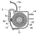
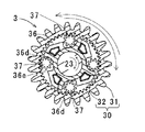
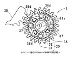
- FIG. 2A is a cross-sectional view taken along line DD in FIG. 3 is a schematic diagram of a one-way clutch 3.
- FIG. 1 is a schematic diagram showing that the bobbin 2 is rotated only in the winding direction of the belt 40 by the lock lever 35 of the one-way clutch 3. It is a schematic diagram showing that the bobbin 2 is rotated only in the winding direction of the belt 40 by the lock lever 35 of the one-way clutch 3.
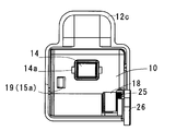
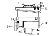
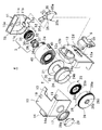
- 3 is an exploded perspective view of the apparatus main body 4.
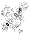
- FIG. It is a disassembled perspective view of the apparatus main body 4 seen from the angle different from FIG. 4 is a perspective view of the apparatus main body 4.
- FIG. 4 is a left side view of the fixing frame member 6.
- FIG. 4 is a right side view of the fixing frame member 6.
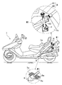
- FIG. It is a figure showing the state where umbrella M1 which is an example of a long article was held in motorcycle 7 using the article holding device of this example.
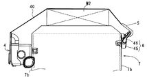
- 2 is a schematic cross-sectional view showing a state in which a bag M2 is fixed to a loading platform 8b of a motorcycle 7 using the apparatus main body 4 and a frame member 6.
- FIG. 3 is a perspective view showing a state in which a bag M2 is fixed to a loading platform 8b of a motorcycle 7 using the apparatus main body 4 and a frame member 6.
- the article holding device according to the present embodiment is used in a state of being attached to the article placement section or the vicinity thereof, and can restrain the article M (umbrella M1, bag M2) to the article placement section.
- the article holding device of this example includes a device main body 4 and a frame member 6 which is an example of a latching portion.
- the apparatus main body 4 makes the case 1 as a housing, the winding bobbin 2 pivotally supported in the case 1, and the bobbin 2 rotatable only in the winding direction of the belt 40.
- the case 1 covers a rectangular solid body 10, a side cover 11 attached to one side surface of the body 10 and closing the side surface, and a rear surface of the body 10.
- This is a hollow housing having a rear cover 12.
- the main body 10 has an opening 13 in which a part of the rear surface side (the surface on which the rear cover 12 is attached) on the upper surface is notched, an attachment locking leg 14 provided on the front surface so as to protrude forward, A shaft portion 16 provided so as to protrude inward from the inner wall of the side surface opposite to the side to which the side cover 11 is attached, and a damper 29 provided on the outside of the side surface provided with the shaft portion 16 are mounted.
- the mounting frame 17, the window 18 (FIG. 2C) in which a part of the front and lower corners (the mounting frame 17 side) is cut out, and the side surface to which the side cover 11 is attached on the upper and lower surfaces and the front surface.
- a plurality of locking holes 19 provided on the side.
- the locking leg 14 is configured to elastically engage with an attachment hole provided in or near the article placement portion by elastic claws 14a provided on both side surfaces.
- the shaft portion 16 extends to a cylindrical portion 24 of the bobbin 2 to be described later, locks an inner end 25a of the winding spring 25 in a not-shown locking groove, and pivotally supports a gear member 26 that rotates integrally with the bobbin 2. To do.
- Rotating damper 29 that brakes via gear member 26 is attached to mounting frame portion 17.
- the damper 29 is fixed to the mounting frame portion 17 and has a gear 29 a that meshes with an outer gear 28 provided on the gear member 26.
- the bobbin 22 receives viscous resistance due to the fluid in the damper 29 via the outer gear 29 a and the outer gear 28. Thus, the bobbin 22 is braked so as not to rotate rapidly by the elastic force of the winding spring 25.
- the side cover 11 includes an arrangement portion 11a defined by a flange portion 15 protruding from the upper and lower edges and the front edge toward the inner surface side, and an arrangement portion 11b defined by a wall protruding upward from the lower front side of the flange portion 15.
- the side cover 11 has assembled
- the main body gear 30 which comprises the one-way clutch 3 cooperated with the bobbin side mentioned later with respect to the arrangement
- the lock lever 35 is set at the operation surface 35a on the lower outer surface, and is provided with a shaft portion 35b provided on both front side surfaces, a claw portion 36 provided on the narrowed tip portion on the upper side, and substantially in the middle.
- the shaft hole 35c is provided and penetrated in the thickness direction.
- a shaft S1 is mounted in the shaft hole 35c, and a shaft S2 is mounted in the hole 11e.
- the above-described lock lever 35 is assembled so as to be swingable about the shaft portion 35b as a fulcrum by fitting the shaft portions 35b on both sides of the side cover 11 to the corresponding shaft holes 11d.
- the inclined posture shown by the solid line by the tension biasing spring 34 assembled in a state where the corresponding end portions are locked to the shafts S1 and S2, and the counterclockwise with the shaft portion 35b as a fulcrum. It is switched and held at two positions with a substantially standing posture shown by a one-dot chain line rotated around.
- the rear cover 12 has a shape that allows the rear side (front side) of the main body 10 to be fitted inside, and is provided on the upper side of the outlet 12a provided at the center and the outlet 12a.
- a window 12d exposing 35a.
- the rear cover 12 is integrated with the main body 10 by fixing means such as adhesion, welding, and engagement structure (not shown).
- fixing means such as adhesion, welding, and engagement structure (not shown).
- the drawing end of the belt 40 wound around the winding portion 20 of the bobbin 2 described later is drawn out from the inside of the main body through the outlet 12a.
- the belt 40 is provided with a connecting portion 41 having a loop shape at the leading end, and the hook 5 is attached to the loop-shaped leading end portion of the connecting portion 41.
- the front end of the hook 5 is bent to the back side, and the lower side of the back side is provided with a shaft-like engaging portion 5a into which the loop-shaped front end portion of the connecting portion 41 is inserted, and on the opposite side of the back side.
- An upward arrow 5b is engraved on the lower side of the front (see FIGS. 1A and 2A).
- the shape of the hook 5 is not limited to this example as long as it can be easily connected to the front end portion of the belt 40 and can be hooked to the engaging portion 12b of the rear cover 12 and the frame member 6.
- the bobbin 2 includes a winding portion 20 around which the belt 40 is wound, flange portions 21 and 22 provided on both sides of the winding portion 20, and a shaft portion 23 protruding outward from the center of the flange portion 21. And a cylindrical portion 24 that is integrated with the outer surface of the flange portion 22 to form a winding spring accommodating portion, and is wound in the belt winding direction by a winding spring 25 disposed in the cylindrical portion 24. A rotational force is applied.
- the winding part 20 has a double structure as shown in FIGS.
- the winding portion 20 forms a locking portion (not shown) that locks the base end of the belt 40 on the outer peripheral side, and the winding portion 20 is wound in a state where the shaft portion 23 is coupled to the end surface of the flange portion 22 at the center.
- the flange portion 21 is disposed through the inside of the turning portion.
- the cylinder part 24 of the flange part 22 has a plurality of claws 24a provided on the outer periphery and a locking part 24b in which a part of the partition wall is cut out.
- the winding spring 25 is disposed in the cylindrical portion 24.
- the inner end 25a of the winding spring 25 is locked in the locking groove of the shaft portion 16, and the outer end 25b of the winding spring 25 is locked in the locking portion 24b.
- the winding spring 25 applies an urging force in the direction in which the belt 40 is wound around the bobbin 2.
- a gear member 26 interposed between the cylindrical portion 24 and a rotary damper 29 is connected.
- the gear member 26 has a double cylinder shape in which the outline shape closes the outer end surface and forms the inner cylinder 27, and a plurality of locking holes 26a provided on the outer periphery and a shaft that penetrates through the center of the outer end surface. It has a boss portion 26c bordering the hole 26b and the shaft hole 26b, and an outer gear 28 provided around the outer end surface side.
- the gear member 26 is integrated by engaging the claw 24a with the locking hole 26a from the inside with respect to the cylindrical portion 24.
- the gear member 26 inserts the main body side shaft portion 16 into the shaft hole 26b, and then the inner end 25a of the winding spring 25 is locked in the locking groove of the shaft portion 16, and the winding spring.
- the outer end 25b of 25 is hooked on a hanging portion 26d provided on the gear member 26 and is wound around.
- the gear member 26 is integrated with the cylindrical portion 24 by the engagement of the locking hole 26a and the claw 24a.
- a part of the outer gear 28 is exposed to the main body side window 18 and meshes with the gear 29 a of the damper 29.
- the one-way clutch 3 is assembled to the bobbin side shaft portion 23 when the side cover 11 is assembled to the main body 10.
- the assembly procedure may be other than this.
- the one-way clutch 3 includes a main body gear 30, a gear holder 36 coupled to the shaft portion 23, and a plurality of (four in this example) arranged to rotate freely on the gear holder 36. ), And the bobbin 2 is allowed to rotate in the direction in which the belt 40 is wound by the operation of the lock lever 35, and the opposite direction, that is, the direction in which the belt 40 is pulled. It can be switched to a state that restricts the rotation to.
- the main body gear 30 has a substantially cylindrical shape, and has a shaft hole 30a that penetrates the outer end side to fit the shaft portion 23, a boss portion 30b that protrudes from the outer end surface and fits into the support hole 11c, and an outer periphery. It has an outer gear 31 provided and an inner gear 32 provided at a part of the inner periphery, and is rotatably supported between the support hole 11c and the large diameter periphery of the gear holder 36. A claw portion 35d of the lock lever 35 is engaged with and disengaged from the outer gear 31. A planetary gear 37 meshes with the inner gear 32.
- the gear holder 36 has a substantially cylindrical shape.
- the gear holder 36 is provided around one end of the cylinder and is fitted to an inner peripheral portion that is the maximum inner diameter of the main body gear 30.
- the shaft portion 23 projects from the flange portion 36 a.
- It has a plurality of (four in this example) hollow portions 36d into which the tooth portions 37 are loosely fitted.
- Each hollow portion 36d is set to a size that allows the planetary gear 37 to be accommodated with a margin, and one end side in the same direction is formed in the corner portion 36e.
- the frame member 6 includes a base 45 and a ring 46 attached to the base 45 as shown in FIGS. 8A to 8C, for example.
- the base 45 is provided with a locking leg 47 with an elastic claw 47a for attachment.
- the ring 46 is supported so as to be swingable by a predetermined angle with respect to the base 45.
- the frame member 6 only needs to have a shape that can hook the hook 5 described later (a shape that can hook the hook 5 and can hold the hook 5 in a hooked state).
- FIG. 9 is a diagram showing a state in which an umbrella M1, which is an example of a long article, is held on the motorcycle 7 using the article holding apparatus of this example.
- FIGS. 10A and 10B are views showing a state in which the bag M2 is held on the motorcycle 7 by using the article holding device of this example.
- the apparatus main body of the article holding apparatus is placed on the side frame 7a above the rear wheel of the motorcycle 7. 4 and the frame member 6 are attached at intervals, and the auxiliary hold 9 is attached to the footrest 8a.
- the apparatus main body 4 inserts the latching leg 14 into the mounting hole provided in the side frame 7a, and engages the elastic claw 14a of the latching leg 14 with the back surface of the side frame 7a. 7a is fixed.
- the frame member 6 engages the elastic claw 47a of the locking leg 47 with the back surface of the side frame 7a by inserting the locking leg 47 into a mounting hole provided slightly above the fixing position of the apparatus body 4 in the side frame 7a. By combining, it is fixed to the side frame 7a.
- the auxiliary hold 9 forms a restriction hole 9a that is penetrated obliquely upward for inserting the tip of the umbrella M1.
- the umbrella M ⁇ b> 1 is restrained by a drawn-out portion of the belt 40 in which the tip is inserted into the restriction hole 9 a of the auxiliary hold 9 and the upper side is pulled out from the apparatus body 5 and the hook 5 is hooked on the ring 46 of the frame member 6. Is retained.
- the belt 40 moves the hook 5 to the upper side of the case 1 (arrow 5b) to remove it from the locking portion 12b, and is hooked on the ring 46 of the frame member 6 with one touch.
- the belt drawing portion that restrains the umbrella M1 on the side frame 7a is stabilized without loosening.
- the holding state can be maintained.
- the user can use the function of preventing the belt 40 from loosening by switching the lock lever 35 to the on state. That is, an operation of pressing the lock lever 35 is performed in a use state where the umbrella M1 is restrained by the portion of the belt 40 pulled out from the apparatus main body 4.
- the one-way clutch 3 can be rotated only in the direction in which the bobbin 2 winds up the belt 40, and the belt 40 can be prevented from being pulled out inadvertently, so that an accident caused by the looseness of the belt can be reliably solved ( (Refer FIG.4 (b) and FIG.4 (c)).
- Such a structure allows the belt 40 to be pulled and tensioned to be fixed by tensioning the lock lever 35 when it is desired to hold it more safely and firmly.
- the belt 40 is automatically wound up thereafter, so that good operability and appearance when not in use can be maintained.
- the winding speed of the belt 40 is braked or alleviated by the damper 29, the belt 40 can be smoothly stored in the case by preventing idling during winding of the belt.
- FIG. 10A is a schematic cross-sectional view showing a state in which the bag M2 is fixed to the loading platform 8b of the motorcycle 7 by using the apparatus main body 4 and the frame member 6.
- FIG. 10B is a perspective view showing a state in which the bag M ⁇ b> 2 is fixed to the loading platform 8 b of the motorcycle 7 using the apparatus main body 4 and the frame member 6.
- the apparatus main body 4 is mounted at a position on the one side surface of the side frame 7b in the motorcycle 7 that is directly below the loading platform 8b, and the side frame 7b has a surface opposite to the one side (the other side).
- the frame member 6 is mounted on the surface.
- the apparatus main body 4 is engaged and fixed by the elastic claws 14a with the locking legs 14 engaged with the mounting holes provided in the side frame 7b.
- the frame member 6 is engaged and fixed by the elastic claws 47a by engaging the engaging legs 47 with respect to the mounting holes provided on the other side surface of the side frame 7b.
- the apparatus main body 4 and the frame member 6 are both attached to the side frame 7b side by the locking legs 14 and 47, but the attaching means is not limited to this and is arbitrarily designed according to the application.
- ⁇ M2 is restrained and held by the drawn-out portion of the belt 40 which is pulled out from the apparatus body 5 and is hooked on the ring 46 of the frame member 6 while being placed on the loading platform 8b. Also in this case, the belt 40 moves the hook 5 to the upper side of the case 1 (arrow 5b), is detached from the locking portion 12b, and is hooked on the ring 46 of the frame member 6 with one touch.
- FIG. 11A and FIG. 11B are perspective views of an article holding device according to a modification of the embodiment of the present invention.
- 11 (a) is a perspective view corresponding to FIG. 7 (a)
- FIG. 11 (b) is a side frame 7c that is an example of a component placement unit. It is a perspective view which shows the state which attached and pulled out a part of belt 40.
- FIG. 11 (a) is a perspective view corresponding to FIG. 7 (a)
- FIG. 11 (b) is a side frame 7c that is an example of a component placement unit. It is a perspective view which shows the state which attached and pulled out a part of belt 40.
- the case 1 is provided with a frame member 6A that is an example of a latching portion.
- the frame member 6 ⁇ / b> A has a substantially inverted U shape including a vertical portion extending perpendicularly to the upper surface from the upper surface of the main body 10 in the case 1 and a horizontal portion connecting the tips of the vertical portions.
- an article is arranged between the upper cover portion 12c and the frame member 6A in the apparatus main body 4, the belt 40 is pulled out from the apparatus main body 4, and the hook 5 at the tip of the belt 40 is hooked on the frame member 6A.
- the article disposed between the upper cover portion 12c and the frame member 6A is restrained and fixed by the belt 40.
- the hook portion (frame member 6A) for hooking the hook 5 is provided on the upper surface of the main body 10 in the case 1, so that the hook portion is different from the article holding device having the hook portion as a separate member. Since the article can be held only by attaching the apparatus main body 4 to the side frame 7c (article placement portion), the number of attachment steps can be reduced by half and the handleability is excellent. Further, since the number of components can be reduced as compared with the article holding device having the latching portion as a separate member, the component cost can be reduced.
- the article holding device of the present invention only has to substantially include the configuration specified in each claim in the claims, and includes those that can be changed by those skilled in the art based on the present embodiment and modifications. It is.
- the specific configuration of the one-way clutch is not limited to the configuration of the present embodiment, and includes any configuration that can be easily conceived by those skilled in the art.
- Case (10 is main body, 11 is side cover, 12 is rear cover) 2 ...
- Bobbin (20 is a winding part, 21 and 22 are flange parts, 23 is a shaft part, 24 is a cylinder part) 3.
- One-way clutch (30 is a main body gear, 31 is an outer gear, 32 is an inner gear, 36 is a gear holder, 37 is a planetary gear) 4 ...
- Device main body (25 is a coil spring, 26 is a gear member, 29 is a damper, 40 is a belt) 5 ... Hook (5a is a locking part) 6 ...
- Frame member (45 is base, 46 is ring, 47 is locking leg) 7 ...
Landscapes
- Engineering & Computer Science (AREA)
- Mechanical Engineering (AREA)
- Vehicle Step Arrangements And Article Storage (AREA)
Abstract
Description
物品を物品配置部に拘束する物品保持装置であって、引出端にフックが設けられたベルトが引き出し可能に巻き取られている装置本体と、前記フックを係止する掛止め部とを備え、前記ベルトを前記装置本体から引き出して前記フックを前記掛止め部に係止することにより、引き出された前記ベルトにより前記物品を前記物品配置部に拘束する物品保持装置。
また、上記(1)の物品保持装置であって、前記装置本体は、前記ベルトが引き出される引出口が形成されたケースと、前記ケース内に回転自在に枢支されて前記ベルトが巻き取られる方向に回転力が与えられたボビンと、前記ボビンの回転速度を制動するダンパーとを有する物品保持装置。
(3)
また、上記(1)または(2)の物品保持装置であって、前記装置本体は、前記ボビンに取り付けられたワンウエイクラッチ及び前記ワンウエイクラッチに離接するロックレバーを有し、前記ワンウエイクラッチが前記ロックレバーの操作により前記ボビンをベルト巻取り方向の回転を許容し、ベルト引張り方向の回転を規制する状態に切り換えられる物品保持装置。
また、上記(1)から(3)のいずれかの物品保持装置であって、前記掛止め部が前記ケースに設けられている物品保持装置。
また、上記(1)から(4)のいずれかの物品保持装置であって、前記装置本体から離れた箇所に取り付けられる補助ホールドをさらに備え、前記補助ホールドには、長尺の前記物品の先端が差し込まれることにより、前記物品を拘束する規制穴が設けられている物品保持装置。
また、上記(5)の物品保持装置であって、前記規制穴は、二輪車のフットレスト廻りに取り付けられる物品保持装置。
本実施形態に係る物品保持装置は、物品配置部またはその付近に取り付けられた状態で使用されて、物品M(傘M1,鞄M2)を物品配置部に拘束することができる。本例の物品保持装置は、装置本体4と、掛止め部の一例である枠部材6と、を備える。このうち、装置本体4は、筐体としてのケース1、ケース1内に回転可能に枢支された巻取り式のボビン2、および、ボビン2をベルト40の巻き取り方向にだけ回転可能にするワンウエイクラッチ3、などを有する。
枠部材6は、例えば図8(a)乃至図8(c)に示すように、ベース45及びベース45に取り付けられたリング46とからなる。ベース45には取付用の弾性爪47a付きの係止脚47が設けられている。リング46はベース45に対して所定角だけ揺動可能に支持されている。但し、枠部材6は、後述するフック5を掛け止めすることのできる形状(フック5を引っ掛けることができ、さらに、フック5を引っ掛けられた状態で保持できる形状)であればよい。
次に、バイクなどの自動二輪車に本例の物品保持装置を用いた例について説明する。図9は、長尺な物品の一例である傘M1を本例の物品保持装置を用いて自動二輪車7に保持した状態を示す図である。また、図10(a)および図10(b)は、鞄M2を本例の物品保持装置を用いて自動二輪車7に保持した状態を示す図である。
図11(a)および図11(b)は、本発明の実施形態の変形例に係る物品保持装置の斜視図である。なお、図11(a)は、図7(a)に対応させた斜視図であり、図11(b)は、本変形例に係る物品保持装置を部品配置部の一例であるサイドフレーム7cに取り付けてベルト40の一部を引き出した状態を示す斜視図である。
2…ボビン(20は巻回部、21と22はフランジ部、23は軸部、24は筒部)
3…ワンウエイクラッチ(30は本体ギア、31は外ギア、32は内ギア、36はギアホルダー、37は遊星歯車)
4…装置本体(25は巻ばね、26はギア部材、29はダンパー、40はベルト)
5…フック(5aは係止部)
6…枠部材(45はベース、46はリング、47は係止脚)
7…自動二輪車(7a,7bはサイドフレーム、8aはフットレスト、8bは荷台)
9…補助ホールド(9aは規制穴)
35…ロックレバー(35aは操作面、35dは爪部)
M…物品(M1は傘、M2は鞄)
Claims (6)
- 物品を物品配置部に拘束する物品保持装置であって、
引出端にフックが設けられたベルトが引き出し可能に巻き取られている装置本体と、前記フックを係止する掛止め部とを備え、
前記ベルトを前記装置本体から引き出して前記フックを前記掛止め部に係止することにより、引き出された前記ベルトにより前記物品を前記物品配置部に拘束することを特徴とする物品保持装置。 - 前記装置本体は、前記ベルトが引き出される引出口が形成されたケースと、前記ケース内に回転自在に枢支されて前記ベルトが巻き取られる方向に回転力が与えられたボビンと、前記ボビンの回転速度を制動するダンパーとを有することを特徴とする請求項1に記載の物品保持装置。
- 前記装置本体は、前記ボビンに取り付けられたワンウエイクラッチ及び前記ワンウエイクラッチに離接するロックレバーを有し、前記ワンウエイクラッチが前記ロックレバーの操作により前記ボビンをベルト巻取り方向の回転を許容し、ベルト引張り方向の回転を規制する状態に切り換えられることを特徴とする請求項1又は2に記載の物品保持装置。
- 前記掛止め部が前記ケースに設けられていることを特徴とする請求項1から3の何れか1項に記載の物品保持装置。
- 前記装置本体から離れた箇所に取り付けられる補助ホールドをさらに備え、
前記補助ホールドには、長尺の前記物品の先端が差し込まれることにより、前記物品を拘束する規制穴が設けられていることを特徴とする請求項1から4の何れか1項に記載の物品保持装置。 - 前記規制穴は、二輪車のフットレスト廻りに取り付けられることを特徴とする請求項5に記載の物品保持装置。
Priority Applications (1)
| Application Number | Priority Date | Filing Date | Title |
|---|---|---|---|
| CN2011800154358A CN102811899A (zh) | 2010-03-31 | 2011-03-28 | 物品保持装置 |
Applications Claiming Priority (2)
| Application Number | Priority Date | Filing Date | Title |
|---|---|---|---|
| JP2010080316A JP2011213131A (ja) | 2010-03-31 | 2010-03-31 | 物品保持装置 |
| JP2010-080316 | 2010-03-31 |
Publications (1)
| Publication Number | Publication Date |
|---|---|
| WO2011125598A1 true WO2011125598A1 (ja) | 2011-10-13 |
Family
ID=44762547
Family Applications (1)
| Application Number | Title | Priority Date | Filing Date |
|---|---|---|---|
| PCT/JP2011/057583 Ceased WO2011125598A1 (ja) | 2010-03-31 | 2011-03-28 | 物品保持装置 |
Country Status (3)
| Country | Link |
|---|---|
| JP (1) | JP2011213131A (ja) |
| CN (1) | CN102811899A (ja) |
| WO (1) | WO2011125598A1 (ja) |
Cited By (1)
| Publication number | Priority date | Publication date | Assignee | Title |
|---|---|---|---|---|
| WO2015192205A1 (en) * | 2014-06-17 | 2015-12-23 | Leo Brian | A snow brush holder attachable to the exterior of a vehicle |
Families Citing this family (1)
| Publication number | Priority date | Publication date | Assignee | Title |
|---|---|---|---|---|
| GB201306831D0 (en) * | 2013-04-15 | 2013-05-29 | St Gallay Martin | Helmet locking device |
Citations (4)
| Publication number | Priority date | Publication date | Assignee | Title |
|---|---|---|---|---|
| JPS5057155U (ja) * | 1973-09-22 | 1975-05-29 | ||
| JPH0731586U (ja) * | 1993-11-22 | 1995-06-13 | 博 栗田 | スクーター用傘ホルダー |
| JPH11228032A (ja) * | 1998-02-19 | 1999-08-24 | Chuo Spring Co Ltd | ダンパー付きコード巻取り装置 |
| JP2002255074A (ja) * | 2001-03-02 | 2002-09-11 | Honda Motor Co Ltd | 荷掛け装置 |
Family Cites Families (2)
| Publication number | Priority date | Publication date | Assignee | Title |
|---|---|---|---|---|
| JP2551027Y2 (ja) * | 1992-01-13 | 1997-10-22 | 積水化学工業株式会社 | 軒樋接続部の流路構造 |
| WO2008006577A1 (de) * | 2006-07-13 | 2008-01-17 | Shanghai Trade Gmbh | Koppelvorrichtung zum anbringen eines zubehörteils oder einer gepäckaufnahmeeinheit im frontbereich eines fahrrades |
-
2010
- 2010-03-31 JP JP2010080316A patent/JP2011213131A/ja active Pending
-
2011
- 2011-03-28 CN CN2011800154358A patent/CN102811899A/zh active Pending
- 2011-03-28 WO PCT/JP2011/057583 patent/WO2011125598A1/ja not_active Ceased
Patent Citations (4)
| Publication number | Priority date | Publication date | Assignee | Title |
|---|---|---|---|---|
| JPS5057155U (ja) * | 1973-09-22 | 1975-05-29 | ||
| JPH0731586U (ja) * | 1993-11-22 | 1995-06-13 | 博 栗田 | スクーター用傘ホルダー |
| JPH11228032A (ja) * | 1998-02-19 | 1999-08-24 | Chuo Spring Co Ltd | ダンパー付きコード巻取り装置 |
| JP2002255074A (ja) * | 2001-03-02 | 2002-09-11 | Honda Motor Co Ltd | 荷掛け装置 |
Cited By (1)
| Publication number | Priority date | Publication date | Assignee | Title |
|---|---|---|---|---|
| WO2015192205A1 (en) * | 2014-06-17 | 2015-12-23 | Leo Brian | A snow brush holder attachable to the exterior of a vehicle |
Also Published As
| Publication number | Publication date |
|---|---|
| JP2011213131A (ja) | 2011-10-27 |
| CN102811899A (zh) | 2012-12-05 |
Similar Documents
| Publication | Publication Date | Title |
|---|---|---|
| CA2196689C (en) | Retractable auxiliary luggage case attachment and security tether mechanism and method | |
| JP2011102116A (ja) | 物体保持装置 | |
| JP5172398B2 (ja) | 自動車シート用物品保持具 | |
| JP2012148614A (ja) | トノカバー装置 | |
| WO2011125598A1 (ja) | 物品保持装置 | |
| JP3737691B2 (ja) | 小物収納装置 | |
| JP2010241292A (ja) | フロアコンソール | |
| JP6168752B2 (ja) | 収納式フック装置 | |
| JP2002264729A (ja) | 車両用格納式フック装置 | |
| JP3874162B2 (ja) | 車両用アームレスト | |
| JP6266446B2 (ja) | トノカバー装置 | |
| JP5607554B2 (ja) | 車両用の荷物固定機構 | |
| JP2013018340A (ja) | シートベルトロックシステム | |
| JP2007024279A (ja) | 折畳み式フック装置 | |
| JP2586880Y2 (ja) | 巻取り装置付きベルト締付具 | |
| JP3162835U (ja) | 自転車用ワイヤー錠 | |
| CN219769758U (zh) | 机动车辆 | |
| KR101728036B1 (ko) | 편의성 향상을 위한 콘솔 암레스트 구조 | |
| JP2004154451A (ja) | ショルダーストラップ用長さ調節具 | |
| JP3246269U (ja) | シートベルト留め具 | |
| JP2007204121A (ja) | 巻取り装置付きバンド | |
| JP2019177815A (ja) | 脱出ハンマー収容具 | |
| JP2017039348A (ja) | 荷締機及び台車 | |
| JP2000185602A (ja) | 車両用荷物保持装置 | |
| JP2008000470A (ja) | ミシン用補助部品 |
Legal Events
| Date | Code | Title | Description |
|---|---|---|---|
| WWE | Wipo information: entry into national phase |
Ref document number: 201180015435.8 Country of ref document: CN |
|
| 121 | Ep: the epo has been informed by wipo that ep was designated in this application |
Ref document number: 11765498 Country of ref document: EP Kind code of ref document: A1 |
|
| WWE | Wipo information: entry into national phase |
Ref document number: 2826/KOLNP/2012 Country of ref document: IN |
|
| NENP | Non-entry into the national phase |
Ref country code: DE |
|
| 122 | Ep: pct application non-entry in european phase |
Ref document number: 11765498 Country of ref document: EP Kind code of ref document: A1 |