WO2011125592A1 - 永久磁石及び永久磁石の製造方法 - Google Patents
永久磁石及び永久磁石の製造方法 Download PDFInfo
- Publication number
- WO2011125592A1 WO2011125592A1 PCT/JP2011/057573 JP2011057573W WO2011125592A1 WO 2011125592 A1 WO2011125592 A1 WO 2011125592A1 JP 2011057573 W JP2011057573 W JP 2011057573W WO 2011125592 A1 WO2011125592 A1 WO 2011125592A1
- Authority
- WO
- WIPO (PCT)
- Prior art keywords
- magnet
- permanent magnet
- sintering
- organometallic compound
- powder
- Prior art date
- Legal status (The legal status is an assumption and is not a legal conclusion. Google has not performed a legal analysis and makes no representation as to the accuracy of the status listed.)
- Ceased
Links
Images


Classifications
-
- H—ELECTRICITY
- H01—ELECTRIC ELEMENTS
- H01F—MAGNETS; INDUCTANCES; TRANSFORMERS; SELECTION OF MATERIALS FOR THEIR MAGNETIC PROPERTIES
- H01F41/00—Apparatus or processes specially adapted for manufacturing or assembling magnets, inductances or transformers; Apparatus or processes specially adapted for manufacturing materials characterised by their magnetic properties
- H01F41/02—Apparatus or processes specially adapted for manufacturing or assembling magnets, inductances or transformers; Apparatus or processes specially adapted for manufacturing materials characterised by their magnetic properties for manufacturing cores, coils, or magnets
- H01F41/0253—Apparatus or processes specially adapted for manufacturing or assembling magnets, inductances or transformers; Apparatus or processes specially adapted for manufacturing materials characterised by their magnetic properties for manufacturing cores, coils, or magnets for manufacturing permanent magnets
- H01F41/0266—Moulding; Pressing
-
- H—ELECTRICITY
- H01—ELECTRIC ELEMENTS
- H01F—MAGNETS; INDUCTANCES; TRANSFORMERS; SELECTION OF MATERIALS FOR THEIR MAGNETIC PROPERTIES
- H01F41/00—Apparatus or processes specially adapted for manufacturing or assembling magnets, inductances or transformers; Apparatus or processes specially adapted for manufacturing materials characterised by their magnetic properties
- H01F41/02—Apparatus or processes specially adapted for manufacturing or assembling magnets, inductances or transformers; Apparatus or processes specially adapted for manufacturing materials characterised by their magnetic properties for manufacturing cores, coils, or magnets
-
- C—CHEMISTRY; METALLURGY
- C22—METALLURGY; FERROUS OR NON-FERROUS ALLOYS; TREATMENT OF ALLOYS OR NON-FERROUS METALS
- C22C—ALLOYS
- C22C38/00—Ferrous alloys, e.g. steel alloys
- C22C38/002—Ferrous alloys, e.g. steel alloys containing In, Mg, or other elements not provided for in one single group C22C38/001 - C22C38/60
-
- C—CHEMISTRY; METALLURGY
- C22—METALLURGY; FERROUS OR NON-FERROUS ALLOYS; TREATMENT OF ALLOYS OR NON-FERROUS METALS
- C22C—ALLOYS
- C22C38/00—Ferrous alloys, e.g. steel alloys
- C22C38/005—Ferrous alloys, e.g. steel alloys containing rare earths, i.e. Sc, Y, Lanthanides
-
- H—ELECTRICITY
- H01—ELECTRIC ELEMENTS
- H01F—MAGNETS; INDUCTANCES; TRANSFORMERS; SELECTION OF MATERIALS FOR THEIR MAGNETIC PROPERTIES
- H01F1/00—Magnets or magnetic bodies characterised by the magnetic materials therefor; Selection of materials for their magnetic properties
- H01F1/01—Magnets or magnetic bodies characterised by the magnetic materials therefor; Selection of materials for their magnetic properties of inorganic materials
- H01F1/03—Magnets or magnetic bodies characterised by the magnetic materials therefor; Selection of materials for their magnetic properties of inorganic materials characterised by their coercivity
- H01F1/032—Magnets or magnetic bodies characterised by the magnetic materials therefor; Selection of materials for their magnetic properties of inorganic materials characterised by their coercivity of hard-magnetic materials
- H01F1/04—Magnets or magnetic bodies characterised by the magnetic materials therefor; Selection of materials for their magnetic properties of inorganic materials characterised by their coercivity of hard-magnetic materials metals or alloys
- H01F1/047—Alloys characterised by their composition
- H01F1/053—Alloys characterised by their composition containing rare earth metals
- H01F1/055—Alloys characterised by their composition containing rare earth metals and magnetic transition metals, e.g. SmCo5
- H01F1/057—Alloys characterised by their composition containing rare earth metals and magnetic transition metals, e.g. SmCo5 and IIIa elements, e.g. Nd2Fe14B
- H01F1/0571—Alloys characterised by their composition containing rare earth metals and magnetic transition metals, e.g. SmCo5 and IIIa elements, e.g. Nd2Fe14B in the form of particles, e.g. rapid quenched powders or ribbon flakes
- H01F1/0572—Alloys characterised by their composition containing rare earth metals and magnetic transition metals, e.g. SmCo5 and IIIa elements, e.g. Nd2Fe14B in the form of particles, e.g. rapid quenched powders or ribbon flakes with a protective layer
-
- H—ELECTRICITY
- H01—ELECTRIC ELEMENTS
- H01F—MAGNETS; INDUCTANCES; TRANSFORMERS; SELECTION OF MATERIALS FOR THEIR MAGNETIC PROPERTIES
- H01F1/00—Magnets or magnetic bodies characterised by the magnetic materials therefor; Selection of materials for their magnetic properties
- H01F1/01—Magnets or magnetic bodies characterised by the magnetic materials therefor; Selection of materials for their magnetic properties of inorganic materials
- H01F1/03—Magnets or magnetic bodies characterised by the magnetic materials therefor; Selection of materials for their magnetic properties of inorganic materials characterised by their coercivity
- H01F1/032—Magnets or magnetic bodies characterised by the magnetic materials therefor; Selection of materials for their magnetic properties of inorganic materials characterised by their coercivity of hard-magnetic materials
- H01F1/04—Magnets or magnetic bodies characterised by the magnetic materials therefor; Selection of materials for their magnetic properties of inorganic materials characterised by their coercivity of hard-magnetic materials metals or alloys
- H01F1/06—Magnets or magnetic bodies characterised by the magnetic materials therefor; Selection of materials for their magnetic properties of inorganic materials characterised by their coercivity of hard-magnetic materials metals or alloys in the form of particles, e.g. powder
- H01F1/08—Magnets or magnetic bodies characterised by the magnetic materials therefor; Selection of materials for their magnetic properties of inorganic materials characterised by their coercivity of hard-magnetic materials metals or alloys in the form of particles, e.g. powder pressed, sintered, or bound together
- H01F1/086—Magnets or magnetic bodies characterised by the magnetic materials therefor; Selection of materials for their magnetic properties of inorganic materials characterised by their coercivity of hard-magnetic materials metals or alloys in the form of particles, e.g. powder pressed, sintered, or bound together sintered
-
- H—ELECTRICITY
- H02—GENERATION; CONVERSION OR DISTRIBUTION OF ELECTRIC POWER
- H02K—DYNAMO-ELECTRIC MACHINES
- H02K15/00—Processes or apparatus specially adapted for manufacturing, assembling, maintaining or repairing of dynamo-electric machines
- H02K15/02—Processes or apparatus specially adapted for manufacturing, assembling, maintaining or repairing of dynamo-electric machines of stator or rotor bodies
- H02K15/03—Processes or apparatus specially adapted for manufacturing, assembling, maintaining or repairing of dynamo-electric machines of stator or rotor bodies having permanent magnets
-
- B—PERFORMING OPERATIONS; TRANSPORTING
- B22—CASTING; POWDER METALLURGY
- B22F—WORKING METALLIC POWDER; MANUFACTURE OF ARTICLES FROM METALLIC POWDER; MAKING METALLIC POWDER; APPARATUS OR DEVICES SPECIALLY ADAPTED FOR METALLIC POWDER
- B22F2998/00—Supplementary information concerning processes or compositions relating to powder metallurgy
-
- B—PERFORMING OPERATIONS; TRANSPORTING
- B22—CASTING; POWDER METALLURGY
- B22F—WORKING METALLIC POWDER; MANUFACTURE OF ARTICLES FROM METALLIC POWDER; MAKING METALLIC POWDER; APPARATUS OR DEVICES SPECIALLY ADAPTED FOR METALLIC POWDER
- B22F2999/00—Aspects linked to processes or compositions used in powder metallurgy
-
- C—CHEMISTRY; METALLURGY
- C22—METALLURGY; FERROUS OR NON-FERROUS ALLOYS; TREATMENT OF ALLOYS OR NON-FERROUS METALS
- C22C—ALLOYS
- C22C2202/00—Physical properties
- C22C2202/02—Magnetic
-
- H—ELECTRICITY
- H01—ELECTRIC ELEMENTS
- H01F—MAGNETS; INDUCTANCES; TRANSFORMERS; SELECTION OF MATERIALS FOR THEIR MAGNETIC PROPERTIES
- H01F1/00—Magnets or magnetic bodies characterised by the magnetic materials therefor; Selection of materials for their magnetic properties
- H01F1/01—Magnets or magnetic bodies characterised by the magnetic materials therefor; Selection of materials for their magnetic properties of inorganic materials
- H01F1/03—Magnets or magnetic bodies characterised by the magnetic materials therefor; Selection of materials for their magnetic properties of inorganic materials characterised by their coercivity
- H01F1/032—Magnets or magnetic bodies characterised by the magnetic materials therefor; Selection of materials for their magnetic properties of inorganic materials characterised by their coercivity of hard-magnetic materials
- H01F1/04—Magnets or magnetic bodies characterised by the magnetic materials therefor; Selection of materials for their magnetic properties of inorganic materials characterised by their coercivity of hard-magnetic materials metals or alloys
- H01F1/047—Alloys characterised by their composition
- H01F1/053—Alloys characterised by their composition containing rare earth metals
- H01F1/055—Alloys characterised by their composition containing rare earth metals and magnetic transition metals, e.g. SmCo5
- H01F1/057—Alloys characterised by their composition containing rare earth metals and magnetic transition metals, e.g. SmCo5 and IIIa elements, e.g. Nd2Fe14B
- H01F1/0571—Alloys characterised by their composition containing rare earth metals and magnetic transition metals, e.g. SmCo5 and IIIa elements, e.g. Nd2Fe14B in the form of particles, e.g. rapid quenched powders or ribbon flakes
- H01F1/0575—Alloys characterised by their composition containing rare earth metals and magnetic transition metals, e.g. SmCo5 and IIIa elements, e.g. Nd2Fe14B in the form of particles, e.g. rapid quenched powders or ribbon flakes pressed, sintered or bonded together
- H01F1/0577—Alloys characterised by their composition containing rare earth metals and magnetic transition metals, e.g. SmCo5 and IIIa elements, e.g. Nd2Fe14B in the form of particles, e.g. rapid quenched powders or ribbon flakes pressed, sintered or bonded together sintered
Definitions
- the present invention relates to a permanent magnet and a method for manufacturing the permanent magnet.
- Permanent magnet motors used in hybrid cars, hard disk drives, and the like have been required to be smaller, lighter, higher in output, and more efficient.
- the permanent magnet embedded in the permanent magnet motor is required to be thin and further improve the magnetic characteristics.
- Permanent magnets include ferrite magnets, Sm—Co magnets, Nd—Fe—B magnets, Sm 2 Fe 17 N x magnets, and Nd—Fe—B magnets with particularly high residual magnetic flux density. Used as a permanent magnet for a permanent magnet motor.
- a powder sintering method is generally used as a manufacturing method of the permanent magnet.
- the powder sintering method first, raw materials are roughly pulverized, and magnet powder is manufactured by finely pulverizing with a jet mill (dry pulverization) or a wet bead mill (wet pulverization). Thereafter, the magnet powder is put into a mold and press-molded into a desired shape while applying a magnetic field from the outside. Then, it is manufactured by sintering the solid magnet powder formed into a desired shape at a predetermined temperature (for example, 800 ° C. to 1150 ° C. for Nd—Fe—B magnets).
- a predetermined temperature for example, 800 ° C. to 1150 ° C. for Nd—Fe—B magnets.
- Nd-based magnets such as Nd—Fe—B have a problem that the heat-resistant temperature is low. Therefore, when an Nd magnet is used for a permanent magnet motor, if the motor is continuously driven, the coercive force and residual magnetic flux density of the magnet are gradually reduced. Therefore, when using an Nd magnet for a permanent magnet motor, in order to improve the heat resistance of the Nd magnet, Dy (dysprosium) or Tb (terbium) having high magnetic anisotropy is added, and the coercive force of the magnet is added. It is intended to further improve the above.
- the magnetic performance of a permanent magnet is basically improved by reducing the crystal grain size of the sintered body because the magnetic properties of the magnet are derived by the single domain fine particle theory.
- the crystal grain size of the sintered body it is necessary to reduce the grain size of the magnet raw material before sintering.
- the crystal grain size is in the range of 0.2 ⁇ m to 1.2 ⁇ m, the crystal grain becomes a single magnetic domain. Therefore, when pulverizing the magnet raw material, it is necessary to pulverize the magnet particles until the particle size satisfies the range.
- a single magnetic domain refers to a region in which only one magnetization direction exists without a domain wall inside in a thermally demagnetized state.
- wet bead mill pulverization which is one of the pulverization methods used when pulverizing magnet raw materials, is filled with beads (media) in a container and rotated, and a slurry in which the raw materials are mixed in a solvent is added. This is a method of grinding and crushing raw materials. Then, by performing wet bead mill pulverization, the magnet raw material can be pulverized to a single domain particle diameter (for example, 0.2 ⁇ m to 1.2 ⁇ m).
- an organic solvent such as toluene, cyclohexane, ethyl acetate, methanol or the like is used as a solvent in which the magnet raw material is mixed. Accordingly, even if the organic solvent is volatilized by performing vacuum drying or the like after pulverization, the C-containing material remains in the magnet. And since the reactivity of Nd and carbon is very high, if a C content remains up to a high temperature in the sintering process, carbide is formed.
- the present invention has been made to solve the above-described conventional problems, and magnet powder containing an organic solvent in wet pulverization is calcined in a hydrogen atmosphere before sintering, thereby containing magnet particles.
- the amount of carbon can be reduced in advance, while V, Mo, Zr, Ta, Ti, W or Nb contained in the organometallic compound can be efficiently and unevenly arranged with respect to the grain boundaries of the magnet,
- a permanent magnet that can suppress the grain growth of the magnet particles during sintering and can prevent the magnetization reversal of each magnet particle by breaking the exchange interaction between the magnet particles, thereby improving the magnetic performance. And it aims at providing the manufacturing method of a permanent magnet.
- the permanent magnet according to the present invention has the structural formula M- (OR) x (wherein M is V, Mo, Zr, Ta, Ti, W or Nb. R is a hydrocarbon).
- the permanent magnet according to the present invention has a structural formula M- (OR) x (wherein M is V, Mo, Zr, Ta, Ti, W, or Nb. R is a substituent composed of a hydrocarbon. And x is an arbitrary integer.)
- the organometallic compound represented by the above formula is wet pulverized in an organic solvent together with the magnet raw material to obtain a magnet powder obtained by pulverizing the magnet raw material and the magnet. Attaching the organometallic compound to the particle surface of the powder, obtaining the calcined body by calcining the magnet powder having the organometallic compound attached to the particle surface in a hydrogen atmosphere, and calcining the calcined body. It is manufactured by a step of forming a molded body by molding and a step of sintering the molded body.
- the permanent magnet according to the present invention is characterized in that the metal forming the organometallic compound is unevenly distributed at grain boundaries of the permanent magnet after sintering.
- the permanent magnet according to the present invention is characterized in that R in the structural formula M- (OR) x is an alkyl group.
- the permanent magnet according to the present invention is characterized in that R in the structural formula M- (OR) x is any one of an alkyl group having 2 to 6 carbon atoms.
- the permanent magnet according to the present invention is characterized in that the amount of carbon remaining after sintering is less than 0.15 wt%.
- the permanent magnet according to the present invention is characterized in that, in the step of pulverizing the magnet raw material, the magnet raw material is pulverized into magnet powder containing magnet powder having a single domain particle diameter.
- the method for producing a permanent magnet according to the present invention has a structural formula M- (OR) x (wherein M is V, Mo, Zr, Ta, Ti, W, or Nb. R is a substitution made of a hydrocarbon)
- the organic metal compound represented by the formula: x is an arbitrary integer) is wet pulverized in an organic solvent together with a magnet raw material to obtain a magnet powder obtained by pulverizing the magnet raw material.
- the method includes a step of calcining in an atmosphere to obtain a calcined body, and a step of sintering the calcined body.
- the method for producing a permanent magnet according to the present invention has a structural formula M- (OR) x (wherein M is V, Mo, Zr, Ta, Ti, W, or Nb. R is a substitution made of a hydrocarbon)
- M is V, Mo, Zr, Ta, Ti, W, or Nb.
- R is a substitution made of a hydrocarbon
- the organic metal compound represented by the formula: x is an arbitrary integer) is wet pulverized in an organic solvent together with a magnet raw material to obtain a magnet powder obtained by pulverizing the magnet raw material.
- a step of attaching the organometallic compound to the particle surface of the magnet powder a step of calcining the magnet powder having the organometallic compound attached to the particle surface in a hydrogen atmosphere to obtain a calcined body, It has the process of forming a molded object by shape
- the method for producing a permanent magnet according to the present invention is characterized in that R in the structural formula M- (OR) x is an alkyl group.
- R in the structural formula M- (OR) x is any one of an alkyl group having 2 to 6 carbon atoms.
- the method for manufacturing a permanent magnet according to the present invention is characterized in that, in the step of pulverizing the magnet raw material with a bead mill, the magnet raw material is pulverized into magnet powder containing magnet powder having a single domain particle diameter.
- the permanent magnet according to the present invention having the above-described configuration, by calcining a compact of magnet powder mixed with an organic solvent in wet pulverization, which is a manufacturing process of a permanent magnet, in a hydrogen atmosphere before sintering, The amount of carbon contained in the magnet particles can be reduced in advance. As a result, it is possible to sinter the entire magnet densely without generating voids between the main phase and the grain boundary phase of the sintered magnet, and to prevent the coercive force from being lowered. . Further, a large number of ⁇ Fe is not precipitated in the main phase of the magnet after sintering, and the magnet characteristics are not greatly deteriorated.
- V, Mo, Zr, Ta, Ti, W, or Nb can be efficiently and unevenly arranged with respect to the grain boundary of the magnet. As a result, it is possible to suppress the grain growth of the magnet particles during sintering and to prevent the magnetization reversal of each magnet particle by breaking the exchange interaction between the magnet particles, thereby improving the magnetic performance It becomes. Moreover, since the addition amount of V, Mo, Zr, Ta, Ti, W or Nb can be made small, the fall of a residual magnetic flux density can be suppressed.
- the magnet powder containing the organic particles in the wet pulverization that is a manufacturing process of the permanent magnet is calcined in a hydrogen atmosphere before sintering, thereby containing the magnet particles.
- the amount of carbon can be reduced in advance.
- a large number of ⁇ Fe is not precipitated in the main phase of the magnet after sintering, and the magnet characteristics are not greatly deteriorated.
- V, Mo, Zr, Ta, Ti, W, or Nb can be efficiently and unevenly arranged with respect to the grain boundary of the magnet. As a result, it is possible to suppress the grain growth of the magnet particles during sintering and to prevent the magnetization reversal of each magnet particle by breaking the exchange interaction between the magnet particles, thereby improving the magnetic performance It becomes. Moreover, since the addition amount of V, Mo, Zr, Ta, Ti, W or Nb can be made small, the fall of a residual magnetic flux density can be suppressed.
- the organic compound is more easily pyrolyzed with respect to the whole magnet particles as compared with the case of calcining the molded magnet particles. be able to. That is, the amount of carbon in the calcined body can be reduced more reliably.
- the permanent magnet of the present invention since the high melting point metals V, Mo, Zr, Ta, Ti, W, or Nb are unevenly distributed at the grain boundaries of the magnet after sintering, V unevenly distributed at the grain boundaries , Mo, Zr, Ta, Ti, W, or Nb suppresses the grain growth of the magnet particles during sintering and disrupts the exchange interaction between the crystal particles after sintering, thereby reversing the magnetization of each crystal particle It is possible to improve the magnetic performance.
- the permanent magnet of the present invention since an organometallic compound composed of an alkyl group is used as the organometallic compound added to the magnet powder, when the magnet powder is calcined in a hydrogen atmosphere, the organometallic compound is used. It is possible to easily perform the thermal decomposition. As a result, the amount of carbon in the calcined body can be more reliably reduced.
- the magnet powder is calcined in a hydrogen atmosphere. In this case, it is possible to perform thermal decomposition of the organometallic compound at a low temperature. As a result, the pyrolysis of the organometallic compound can be more easily performed on the entire magnet powder.
- the amount of carbon remaining after sintering is 0.15 wt% or less, so that no gap is generated between the main phase of the magnet and the grain boundary phase, and the magnet It becomes possible to make the whole into the state sintered precisely, and it can prevent that a residual magnetic flux density falls. Further, a large number of ⁇ Fe is not precipitated in the main phase of the magnet after sintering, and the magnet characteristics are not greatly deteriorated.
- the crystal grains constituting the permanent magnet can each have a single domain structure. As a result, the magnetic performance of the permanent magnet can be greatly improved.
- the carbon powder contained in the magnet particles is obtained by calcining a compact of a magnet powder mixed with an organic solvent in wet pulverization in a hydrogen atmosphere before sintering.
- the amount can be reduced in advance.
- ⁇ Fe is not precipitated in the main phase of the magnet after sintering, and the magnet characteristics are not greatly deteriorated.
- the method for manufacturing a permanent magnet according to the present invention it is possible to manufacture a permanent magnet in which a small amount of V, Mo, Zr, Ta, Ti, W, or Nb is effectively unevenly distributed with respect to the grain boundaries of the magnet. It becomes possible.
- the manufactured permanent magnet it is possible to suppress the grain growth of the magnet particles during sintering and to prevent the magnetization reversal of each magnet particle by breaking the exchange interaction between the magnet particles. The performance can be improved.
- the addition amount of V, Mo, Zr, Ta, Ti, W, or Nb can be made small compared with the past, the fall of a residual magnetic flux density can be suppressed.
- the carbon powder contained in the magnet particles is preliminarily calcined in a hydrogen atmosphere before sintering the magnet powder mixed with the organic solvent in the wet pulverization. Can be reduced. As a result, it is possible to sinter the entire magnet densely without generating voids between the main phase and the grain boundary phase of the sintered magnet, and to prevent the coercive force from being lowered. . Further, ⁇ Fe is not precipitated in the main phase of the magnet after sintering, and the magnet characteristics are not greatly deteriorated.
- the method for manufacturing a permanent magnet according to the present invention it is possible to manufacture a permanent magnet in which a small amount of V, Mo, Zr, Ta, Ti, W, or Nb is effectively unevenly distributed with respect to the grain boundaries of the magnet. It becomes possible.
- the manufactured permanent magnet it is possible to suppress the grain growth of the magnet particles during sintering and to prevent the magnetization reversal of each magnet particle by breaking the exchange interaction between the magnet particles. The performance can be improved.
- the addition amount of V, Mo, Zr, Ta, Ti, W, or Nb can be made small compared with the past, the fall of a residual magnetic flux density can be suppressed.
- the organic compound is more easily pyrolyzed with respect to the whole magnet particles as compared with the case of calcining the molded magnet particles. be able to. That is, the amount of carbon in the calcined body can be reduced more reliably.
- the method for producing a permanent magnet according to the present invention since an organometallic compound composed of an alkyl group is used as the organometallic compound added to the magnet powder, when calcining the magnet powder in a hydrogen atmosphere, Thermal decomposition of the organometallic compound can be easily performed. As a result, the amount of carbon in the calcined body can be more reliably reduced.
- an organometallic compound composed of an alkyl group having 2 to 6 carbon atoms is used as the organometallic compound added to the magnet powder.
- organometallic compound added to the magnet powder When calcination, it is possible to thermally decompose the organometallic compound at a low temperature. As a result, the pyrolysis of the organometallic compound can be more easily performed on the entire magnet powder.
- the crystal grains constituting the manufactured permanent magnet can each have a single domain structure.
- the magnetic performance of the permanent magnet can be greatly improved.
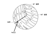
- FIG. 1 is an overall view showing a permanent magnet according to the present invention.
- FIG. 2 is an enlarged schematic view showing the vicinity of the grain boundary of the permanent magnet according to the present invention.
- FIG. 3 is a schematic diagram showing a magnetic domain structure of a ferromagnetic material.
- FIG. 4 is an enlarged schematic view showing the vicinity of the grain boundary of the permanent magnet according to the present invention.
- FIG. 5 is an explanatory view showing a manufacturing process in the first method for manufacturing a permanent magnet according to the present invention.
- FIG. 6 is an explanatory view showing a manufacturing process in the second method for manufacturing a permanent magnet according to the present invention.
- FIG. 7 is a diagram showing a change in the amount of oxygen when the calcination treatment in hydrogen is performed and when it is not performed.
- FIG. 1 is an overall view showing a permanent magnet according to the present invention.
- FIG. 2 is an enlarged schematic view showing the vicinity of the grain boundary of the permanent magnet according to the present invention.
- FIG. 3 is
- FIG. 8 is a graph showing the amount of carbon remaining in the permanent magnets of the permanent magnets of Examples 1 to 4 and Comparative Examples 1 and 2.
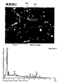
- FIG. 9 is a diagram showing an SEM photograph after sintering of the permanent magnet of Example 1 and the elemental analysis results of the grain boundary phase.
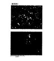
- FIG. 10 is a diagram showing an SEM photograph after sintering of the permanent magnet of Example 2 and the elemental analysis result of the grain boundary phase.
- FIG. 11 is a diagram in which the distribution state of the Nb element is mapped in the same field of view as the SEM photograph after sintering of the permanent magnet of Example 2 and the SEM photograph.
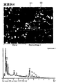
- FIG. 12 is a view showing an SEM photograph after sintering of the permanent magnet of Example 3 and the elemental analysis result of the grain boundary phase.
- FIG. 13 is a diagram in which the distribution state of the Nb element is mapped in the same field of view as the SEM photograph after sintering of the permanent magnet of Example 3 and the SEM photograph.
- FIG. 14 is a diagram showing an SEM photograph after sintering of the permanent magnet of Example 4 and the elemental analysis results of the grain boundary phase.
- FIG. 15 is a diagram in which the distribution state of the Nb element is mapped in the same field of view as the SEM photograph after sintering of the permanent magnet of Example 4 and the SEM photograph.
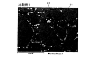
- 16 is a view showing an SEM photograph after sintering of the permanent magnet of Comparative Example 1.
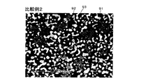
- FIG. 17 is a view showing an SEM photograph after sintering of the permanent magnet of Comparative Example 2.
- FIG. 18 is a graph showing the carbon content in a plurality of permanent magnets manufactured by changing the calcination temperature conditions for the permanent magnets of Example 5 and Comparative Examples 3 and 4.
- FIG. 18 is a graph showing the carbon content in
- FIG. 1 is an overall view showing a permanent magnet 1 according to the present invention.
- 1 has a cylindrical shape, the shape of the permanent magnet 1 varies depending on the shape of the cavity used for molding.
- an Nd—Fe—B magnet is used as the permanent magnet 1 according to the present invention.
- Nb (niobium), V (vanadium), Mo (molybdenum), Zr (zirconium) for increasing the coercive force of the permanent magnet 1 are formed at the interfaces (grain boundaries) of the crystal grains forming the permanent magnet 1.
- Ta tantalum
- Ti titanium
- W tungsten
- each component is Nd: 25 to 37 wt%, Nb, V, Mo, Zr, Ta, Ti, W (hereinafter referred to as Nb etc.): 0.01 to 5 wt%, B: 1 to 2 wt%, Fe (electrolytic iron): 60 to 75 wt%. Further, in order to improve the magnetic characteristics, a small amount of other elements such as Co, Cu, Al and Si may be included.
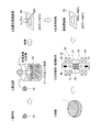
- a part of Nd is made of a refractory metal in the surface portion (outer shell) of the crystal grains of the Nd crystal particles 10 constituting the permanent magnet 1 as shown in FIG.
- a layer 11 hereinafter referred to as a refractory metal layer 11
- Nb or the like is unevenly distributed with respect to the grain boundaries of the Nd crystal particles 10.
- FIG. 2 is an enlarged view of the Nd crystal particles 10 constituting the permanent magnet 1.
- the refractory metal layer 11 is preferably nonmagnetic.
- substitution of Nb or the like is performed by adding an organometallic compound containing Nb or the like before forming a pulverized magnet powder as described later.
- Nd when sintering a magnet powder to which an organometallic compound containing Nb or the like is added, Nb or the like in the organometallic compound uniformly adhered to the particle surface of the Nd crystal particles 10 by wet dispersion is Nd.
- Replacement is performed by diffusing and penetrating into the crystal growth region of the crystal grains 10 to form the refractory metal layer 11 shown in FIG.
- the Nd crystal particles 10 are made of, for example, an Nd 2 Fe 14 B intermetallic compound, and the refractory metal layer 11 is made of, for example, an NbFeB intermetallic compound.
- M- (OR) x (wherein M is V, Mo, Zr, Ta, Ti, W or Nb, R is a hydrocarbon-containing substituent, which may be linear or branched, x is an arbitrary integer, and other organic metal compounds containing Nb and the like (for example, niobium ethoxide, niobium) n-propoxide, niobium n-butoxide, niobium n-hexoxide, etc.) are added to an organic solvent and mixed with the magnet powder in a wet state.
- an organometallic compound containing Nb or the like can be dispersed in an organic solvent, and the organometallic compound containing Nb or the like can be uniformly attached to the surface of the Nd crystal particles 10.
- M- (OR) x (wherein M is V, Mo, Zr, Ta, Ti, W or Nb. R is a substituent composed of hydrocarbon, which may be linear or branched. And x is an arbitrary integer.)
- a metal alkoxide is an organometallic compound that satisfies the structural formula.
- the metal alkoxide is represented by a general formula M (OR) n (M: metal element, R: organic group, n: valence of metal or metalloid).
- metal or semimetal forming the metal alkoxide W, Mo, V, Nb, Ta, Ti, Zr, Ir, Fe, Co, Ni, Cu, Zn, Cd, Al, Ga, In, Ge, Sb, Y, lanthanide, etc. are mentioned.
- a refractory metal is particularly used.
- V, Mo, Zr, Ta, Ti, W or Nb among refractory metals in order to prevent mutual diffusion with the main phase of the magnet during sintering as will be described later.
- alkoxide is not particularly limited, and examples thereof include methoxide, ethoxide, propoxide, isopropoxide, butoxide, alkoxide having 4 or more carbon atoms, and the like.
- those having a low molecular weight are used for the purpose of suppressing residual coal by low-temperature decomposition as described later.
- methoxide having 1 carbon is easily decomposed and difficult to handle, ethoxide, methoxide, isopropoxide, propoxide, butoxide, etc., which are alkoxides having 2 to 6 carbon atoms contained in R, are used. It is preferable.
- M- (OR) x (wherein, M is V, Mo, Zr, Ta, Ti, W, or Nb as an organometallic compound to be added to the magnet powder.
- R is an alkyl group. May be linear or branched, x is an arbitrary integer), and more preferably M- (OR) x (wherein M is V, Mo, Zr, Ta, Ti).
- W or Nb R is any alkyl group having 2 to 6 carbon atoms, which may be linear or branched, and x is an arbitrary integer. desirable.
- the molded body formed by compacting is fired under appropriate firing conditions, it is possible to prevent Nb and the like from diffusing and penetrating (solid solution) into the Nd crystal particles 10.
- Nb etc. can be unevenly distributed only to a grain boundary after sintering.
- the core Nd 2 Fe 14 B intermetallic compound phase occupies a high volume ratio.
- an organic metal compound when an organic metal compound is mixed in an organic solvent and wet-added to the magnet powder, an organic compound such as an organic metal compound or an organic solvent remains in the magnet even if the organic solvent is volatilized later by vacuum drying or the like. Will be.
- the reactivity of Nd and carbon is very high, if a C content remains up to a high temperature in the sintering process, carbide is formed.
- the amount of carbon contained in the magnet particles can be reduced in advance by performing a hydrogen calcining process described later before sintering.
- the sintered Nd crystal particles 10 are in a dense state, it is considered that exchange interaction propagates between the Nd crystal particles 10.
- the non-magnetic refractory metal layer 11 coated on the surface of the Nd crystal particles 10 divides the exchange interaction between the Nd crystal particles 10, and each crystal even when a magnetic field is applied from the outside. Prevents magnetization reversal of particles.
- the refractory metal layer 11 coated on the surface of the Nd crystal particles 10 also functions as a means for suppressing so-called grain growth in which the average particle diameter of the Nd crystal particles 10 increases during sintering of the permanent magnet 1. .
- a mechanism for suppressing grain growth of the permanent magnet 1 by the refractory metal layer 11 will be described with reference to FIG.
- FIG. 3 is a schematic diagram showing a magnetic domain structure of a ferromagnetic material.
- a grain boundary which is a discontinuous boundary surface left between a crystal and another crystal, has excessive energy, grain boundary movement that attempts to reduce energy occurs at a high temperature. Therefore, when the magnet raw material is sintered at a high temperature (for example, 800 ° C. to 1150 ° C. for Nd—Fe—B magnets), the small magnet particles shrink and disappear, and the average particle size of the remaining magnet particles increases. So-called grain growth occurs.
- M- (OR) x (wherein M is V, Mo, Zr, Ta, Ti, W, or Nb.
- R is a substituent composed of hydrocarbon, which may be linear or branched.
- x is an arbitrary integer, Nb or the like, which is a refractory metal, is unevenly distributed at the interface of the magnet particles as shown in FIG. And this unevenly distributed refractory metal prevents the movement of grain boundaries generated at high temperatures, and can suppress grain growth.
- the particle diameter D of the Nd crystal particles 10 is 0.2 ⁇ m to 1.2 ⁇ m, preferably about 0.3 ⁇ m.
- the thickness d of the refractory metal layer 11 is about 2 nm, the growth of Nd magnet particles during sintering can be suppressed, and exchange interaction between the sintered crystal particles can be interrupted. it can.
- the thickness d of the refractory metal layer 11 becomes too large, the content of non-magnetic components that do not exhibit magnetism increases, so the residual magnetic flux density decreases.
- the particle diameter D of the Nd crystal particles 10 is set to 0.2 ⁇ m to 1.2 ⁇ m, preferably about 0.3 ⁇ m, the crystal particles can be made into a single magnetic domain. As a result, the magnetic performance of the permanent magnet 1 can be dramatically improved.
- the refractory metal layer 11 does not need to be a layer composed of only an Nb compound, a V compound, a Mo compound, a Zr compound, a Ta compound, a Ti compound or a W compound (hereinafter referred to as a compound such as Nb). It may be a layer composed of a mixture of a compound and an Nd compound. In that case, a layer made of a mixture of a compound such as Nb and the Nd compound is formed by adding the Nd compound. As a result, liquid phase sintering during the sintering of the Nd magnet powder can be promoted.
- the Nd compounds to be added include NdH 2 , neodymium acetate hydrate, neodymium (III) acetylacetonate trihydrate, neodymium (III) 2-ethylhexanoate, neodymium (III) hexafluoroacetylacetonate Hydrates, neodymium isopropoxide, neodynium (III) phosphate n hydrate, neodymium trifluoroacetylacetonate, neodymium trifluoromethanesulfonate, and the like are desirable.
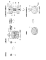
- FIG. 5 is an explanatory view showing a manufacturing process in the first manufacturing method of the permanent magnet 1 according to the present invention.
- an ingot made of a predetermined fraction of Nd—Fe—B (eg, Nd: 32.7 wt%, Fe (electrolytic iron): 65.96 wt%, B: 1.34 wt%) is manufactured. Thereafter, the ingot is roughly pulverized to a size of about 200 ⁇ m by a stamp mill or a crusher. Alternatively, the ingot is melted, flakes are produced by strip casting, and coarsely pulverized by hydrogen crushing. Thereby, coarsely pulverized magnet powder 31 is obtained.
- Nd—Fe—B eg, Nd: 32.7 wt%, Fe (electrolytic iron): 65.96 wt%, B: 1.34 wt
- the coarsely pulverized magnet powder 31 is finely pulverized to a predetermined size or less (for example, 0.1 ⁇ m to 5.0 ⁇ m), more preferably to a single domain particle diameter (for example, 0.2 ⁇ m to 1.2 ⁇ m) by a wet method using a bead mill and a solvent.
- the magnetic powder is dispersed therein to produce a slurry 42.
- 4 kg of toluene is used as a solvent for 0.5 kg of magnet powder.
- an organometallic compound containing Nb or the like is added to the magnet powder during wet pulverization.
- the organometallic compound containing Nb or the like is dispersed in the solvent together with the magnet powder.
- the organometallic compound to be dissolved is M- (OR) x (wherein M is V, Mo, Zr, Ta, Ti, W or Nb, and R is any alkyl group having 2 to 6 carbon atoms). And may be linear or branched, x is an arbitrary integer) (for example, niobium ethoxide, niobium n-propoxide, niobium n-butoxide, niobium n-hexoxide, etc.) ) Is desirable.
- the amount of the organometallic compound containing Nb or the like to be dissolved is not particularly limited, but the content of Nb or the like with respect to the magnet after sintering is 0.001 wt% to 10 wt%, preferably 0.01 wt% to 5 wt%. An amount is preferred. Further, the fine powder having an average particle size of the single magnetic domain particles only needs to be composed mainly of magnet particles having a single magnetic domain particle size, and may include magnet particles other than the single magnetic domain particle size.
- Detailed dispersion conditions are as follows. ⁇ Dispersion equipment: Bead mill ⁇ Dispersion media: Zirconia beads
- the solvent used for pulverization is an organic solvent, but the type of the solvent is not particularly limited, alcohols such as isopropyl alcohol, ethanol and methanol, esters such as ethyl acetate, lower hydrocarbons such as pentane and hexane, Aromatics such as benzene, toluene and xylene, ketones, mixtures thereof and the like can be used.
- alcohols such as isopropyl alcohol, ethanol and methanol
- esters such as ethyl acetate
- lower hydrocarbons such as pentane and hexane
- Aromatics such as benzene, toluene and xylene, ketones, mixtures thereof and the like can be used.
- the produced slurry 42 is dried in advance by vacuum drying or the like before molding, and the dried magnet powder 43 is taken out. Thereafter, the dried magnet powder is compacted into a predetermined shape by the molding device 50.
- the compacting there are a dry method in which the above-mentioned dried fine powder is filled in the cavity and a wet method in which the slurry 42 is filled in the cavity without drying, but the present invention exemplifies the case where the dry method is used. To do.
- the organic solvent or the organometallic compound solution can be volatilized in the firing stage after molding.
- the molding apparatus 50 includes a cylindrical mold 51, a lower punch 52 that slides up and down with respect to the mold 51, and an upper punch 53 that also slides up and down with respect to the mold 51. And a space surrounded by them constitutes the cavity 54.
- the molding apparatus 50 has a pair of magnetic field generating coils 55 and 56 disposed above and below the cavity 54, and applies magnetic field lines to the magnet powder 43 filled in the cavity 54.
- the applied magnetic field is, for example, 1 MA / m.
- the dried magnet powder 43 is filled into the cavity 54. Thereafter, the lower punch 52 and the upper punch 53 are driven, and pressure is applied in the direction of the arrow 61 to the magnetic powder 43 filled in the cavity 54 to perform molding. Simultaneously with the pressurization, a pulse magnetic field is applied to the magnetic powder 43 filled in the cavity 54 by the magnetic field generating coils 55 and 56 in the direction of the arrow 62 parallel to the pressurization direction. Thereby orienting the magnetic field in the desired direction. Note that the direction in which the magnetic field is oriented needs to be determined in consideration of the magnetic field direction required for the permanent magnet 1 formed from the magnet powder 43.
- the slurry when using the wet method, the slurry may be injected while applying a magnetic field to the cavity 54, and wet molding may be performed by applying a magnetic field stronger than the initial magnetic field during or after the injection. Further, the magnetic field generating coils 55 and 56 may be arranged so that the application direction is perpendicular to the pressing direction.
- the compact 71 formed by compacting is held in hydrogen by holding it in a hydrogen atmosphere at 200 ° C. to 900 ° C., more preferably 400 ° C. to 900 ° C. (eg 600 ° C.) for several hours (eg 5 hours).
- the amount of hydrogen supplied during calcination is 5 L / min.
- decarbonization is performed in which the remaining organic compound is thermally decomposed to reduce the amount of carbon in the calcination body.
- the calcination treatment in hydrogen is performed under the condition that the carbon content in the calcined body is 0.15 wt% or less, more preferably 0.1 wt% or less. Accordingly, the entire permanent magnet 1 can be densely sintered by the subsequent sintering process, and the residual magnetic flux density and coercive force are not reduced.
- the molded body 71 calcined by the above-described calcining treatment in hydrogen has a problem that NdH 3 exists and is easily combined with oxygen.
- the molded body 71 is preliminarily hydrogenated. Since it moves to the below-mentioned baking without making it contact with external air after baking, a dehydrogenation process becomes unnecessary. During the firing, hydrogen in the molded body is released.
- the sintering process which sinters the molded object 71 calcined by the calcination process in hydrogen is performed.
- a sintering method of the molded body 71 it is also possible to use pressure sintering which sinters in a state where the molded body 71 is pressed in addition to general vacuum sintering.
- the temperature is raised to about 800 ° C. to 1080 ° C. at a predetermined rate of temperature rise and held for about 2 hours. During this time, vacuum firing is performed, but the degree of vacuum is preferably 10 ⁇ 4 Torr or less. Thereafter, it is cooled and heat treated again at 600 ° C. to 1000 ° C. for 2 hours.
- the permanent magnet 1 is manufactured as a result of sintering.
- pressure sintering examples include hot press sintering, hot isostatic pressing (HIP) sintering, ultrahigh pressure synthetic sintering, gas pressure sintering, and discharge plasma (SPS) sintering.
- HIP hot isostatic pressing
- SPS discharge plasma
- the SPS is uniaxial pressure sintering that pressurizes in a uniaxial direction and is sintered by current sintering. Sintering is preferably used.
- FIG. 6 is an explanatory view showing a manufacturing process in the second manufacturing method of the permanent magnet 1 according to the present invention.
- the process until the slurry 42 is generated is the same as the manufacturing process in the first manufacturing method already described with reference to FIG.
- the produced slurry 42 is dried in advance by vacuum drying or the like before molding, and the dried magnet powder 43 is taken out. Thereafter, the dried magnet powder 43 is calcined in hydrogen by holding it in a hydrogen atmosphere at 200 ° C. to 900 ° C., more preferably 400 ° C. to 900 ° C. (eg 600 ° C.) for several hours (eg 5 hours).
- the amount of hydrogen supplied during calcination is 5 L / min.
- decarbonization is performed in which the remaining organic compound is thermally decomposed to reduce the amount of carbon in the calcination body.
- the calcination treatment in hydrogen is performed under the condition that the carbon content in the calcined body is 0.15 wt% or less, more preferably 0.1 wt% or less. Accordingly, the entire permanent magnet 1 can be densely sintered by the subsequent sintering process, and the residual magnetic flux density and coercive force are not reduced.
- dehydrogenation treatment is performed by holding the powder-like calcined body 82 calcined by calcination in hydrogen at 200 to 600 ° C., more preferably at 400 to 600 ° C. for 1 to 3 hours in a vacuum atmosphere. I do.
- the degree of vacuum is preferably 0.1 Torr or less.
- FIG. 7 shows the magnet powder with respect to the exposure time when the Nd magnet powder that has been calcined in hydrogen and the Nd magnet powder that has not been calcined in hydrogen are exposed to an atmosphere having an oxygen concentration of 7 ppm and an oxygen concentration of 66 ppm, respectively. It is the figure which showed the amount of oxygen in the inside.
- the oxygen content in the magnet powder increases from 0.4% to 0.8% in about 1000 seconds.
- the powder-like calcined body 82 subjected to the dehydrogenation treatment is compacted into a predetermined shape by the molding apparatus 50.
- the details of the molding apparatus 50 are the same as the manufacturing steps in the first manufacturing method already described with reference to FIG.
- a sintering process for sintering the formed calcined body 82 is performed.
- the sintering process is performed by vacuum sintering, pressure sintering, or the like, as in the first manufacturing method described above. Since the details of the sintering conditions are the same as those in the manufacturing process in the first manufacturing method already described, description thereof will be omitted. And the permanent magnet 1 is manufactured as a result of sintering.
- the first manufacturing method in which the magnet particles after molding are calcined in hydrogen are used.
- the thermal decomposition of the remaining organic compound can be more easily performed on the entire magnet particle. That is, it becomes possible to more reliably reduce the amount of carbon in the calcined body as compared with the first manufacturing method.
- the molded body 71 moves to firing without being exposed to the outside air after hydrogen calcination, so that a dehydrogenation step is unnecessary. Therefore, the manufacturing process can be simplified as compared with the second manufacturing method.
- the dehydrogenation step is not necessary when the firing is performed without contact with the outside air after the hydrogen calcination.
- Example 1 The alloy composition of the neodymium magnet powder of Example 1 is Nd more than the fraction based on the stoichiometric composition (Nd: 26.7 wt%, Fe (electrolytic iron): 72.3 wt%, B: 1.0 wt%).
- Nd / Fe / B 32.7 / 65.96 / 1.34 at wt%.
- 5 wt% of niobium ethoxide as an organometallic compound was added to the pulverized neodymium magnet powder.
- toluene was used as an organic solvent for wet grinding.
- the calcination treatment was performed by holding the magnet powder before molding at 600 ° C. for 5 hours in a hydrogen atmosphere.
- the amount of hydrogen supplied during calcination is 5 L / min.
- the sintered calcined body was sintered by SPS sintering.
- the other steps are the same as those in [Permanent magnet manufacturing method 2] described above.
- Example 2 The organometallic compound to be added was niobium n-propoxide. Other conditions are the same as in the first embodiment.
- Example 3 The organometallic compound to be added was niobium n-butoxide. Other conditions are the same as in the first embodiment.
- Example 4 The organometallic compound to be added was niobium n-hexoxide. Other conditions are the same as in the first embodiment.
- Example 5 The molded calcined body was sintered by vacuum sintering instead of SPS sintering. Other conditions are the same as in the first embodiment.
- FIG. 8 is a graph showing the carbon content [wt%] in the permanent magnets of Examples 1 to 4 and Comparative Examples 1 and 2. As shown in FIG. 8, it can be seen that Examples 1 to 4 can greatly reduce the amount of carbon remaining in the magnet particles as compared with Comparative Examples 1 and 2. In particular, in Examples 1 to 4, the amount of carbon remaining in the magnet particles can be 0.15 wt% or less, and in Examples 2 to 4, the amount of carbon remaining in the magnet particles is 0.1 wt% or less. can do.
- Example 1 and Comparative Example 1 when the same organometallic compound is added, when the calcination treatment in hydrogen is performed, the calcination treatment in hydrogen is not performed. In comparison, it can be seen that the amount of carbon in the magnet particles can be greatly reduced. That is, it can be seen that so-called decarbonization can be performed in which the organic compound is thermally decomposed by a calcining treatment in hydrogen to reduce the amount of carbon in the calcined body. As a result, it is possible to prevent dense sintering of the entire magnet and a decrease in coercive force.
- M- (OR) x (wherein M is V, Mo, Zr, Ta, Ti, W or Nb. R is a hydrocarbon) A substituent, which may be linear or branched. X is an arbitrary integer.)
- an organometallic compound represented by (2) is added, the magnet is compared with the case where another organometallic compound is added. It can be seen that the amount of carbon in the particles can be greatly reduced. That is, the organometallic compound to be added is M- (OR) x (wherein M is V, Mo, Zr, Ta, Ti, W or Nb. R is a substituent composed of hydrocarbon, However, it may be branched.
- organometallic compound represented by (2) it is understood that decarbonization can be easily performed in the calcination treatment in hydrogen. As a result, it is possible to prevent dense sintering of the entire magnet and a decrease in coercive force. Further, when an organometallic compound composed of an alkyl group, more preferably an organometallic compound composed of an alkyl group having 2 to 6 carbon atoms, is used as the organometallic compound to be added, the magnet powder is calcined in a hydrogen atmosphere. In this case, it becomes possible to perform thermal decomposition of the organometallic compound at a low temperature. Thereby, the thermal decomposition of the organometallic compound can be more easily performed on the entire magnet particle.
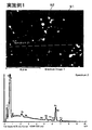
- FIG. 9 is a diagram showing an SEM photograph after sintering of the permanent magnet of Example 1 and the elemental analysis results of the grain boundary phase.
- FIG. 10 is a diagram showing an SEM photograph after sintering of the permanent magnet of Example 2 and the elemental analysis results of the grain boundary phase.
- FIG. 11 is a diagram in which the distribution state of the Nb element is mapped in the same field of view as the SEM photograph after sintering of the permanent magnet of Example 2 and the SEM photograph.
- FIG. 12 is a view showing an SEM photograph after sintering of the permanent magnet of Example 3 and the elemental analysis results of the grain boundary phase.
- FIG. 13 is a diagram in which the Nb element distribution state is mapped in the same field of view as the SEM photograph and the SEM photograph after sintering of the permanent magnet of Example 3.
- FIG. 14 is an SEM photograph after sintering of the permanent magnet of Example 4 and the results of elemental analysis of the grain boundary phase.
- FIG. 15 is a diagram in which the Nb element distribution state is mapped in the same field of view as the SEM photograph after sintering of the permanent magnet of Example 4 and the SEM photograph. As shown in FIGS.
- Nb is detected from the grain boundary phase. That is, in the permanent magnets of Examples 1 to 4, it can be seen that in the grain boundary phase, a phase of NbFe-based intermetallic compound in which a part of Nd is substituted with Nb is generated on the surface of the main phase particle.
- the white portion indicates the distribution of the Nb element.
- the white portion of the mapping diagram (that is, the Nb element) is unevenly distributed around the main phase. That is, it can be seen that in the permanent magnet of Example 2, Nb is not diffused from the grain boundary phase to the main phase, and Nb is unevenly distributed at the grain boundaries of the magnet.
- the white portion indicates the distribution of the Nb element. Referring to the SEM photograph and mapping diagram of FIG. 13, the white portion (that is, Nb element) of the mapping diagram is unevenly distributed around the main phase.
- the white portion indicates the distribution of the Nb element. Referring to the SEM photograph and mapping diagram of FIG. 15, the white portion (that is, Nb element) of the mapping diagram is unevenly distributed around the main phase. That is, it can be seen that in the permanent magnet of Example 4, Nb is not diffused from the grain boundary phase to the main phase, and Nb is unevenly distributed at the grain boundaries of the magnet.
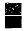
- FIG. 16 is a view showing an SEM photograph after sintering of the permanent magnet of Comparative Example 1.
- FIG. 17 is a view showing an SEM photograph after sintering of the permanent magnet of Comparative Example 2.
- a sintered permanent magnet is formed from a main phase (Nd 2 Fe 14 B) 91 of a neodymium magnet and a grain boundary phase 92 that looks like white spots.
- ⁇ Fe phase is also formed.
- Comparative Example 2 where the amount of residual carbon is larger than in Examples 1 to 4 and Comparative Example 1, in addition to the main phase 91 and the grain boundary phase 92, a large number of ⁇ Fe phases 93 that appear as black bands are formed. .
- ⁇ Fe is generated by carbide remaining during sintering. That is, since the reactivity between Nd and C is very high, if the C-containing material in the organic compound remains at a high temperature in the sintering process as in Comparative Example 2, carbide is formed. As a result, ⁇ Fe is precipitated in the main phase of the sintered magnet by the formed carbide, and the magnetic properties are greatly deteriorated.
- Examples 1 to 4 by using an appropriate organometallic compound as described above and performing a calcination treatment in hydrogen, the organic compound is thermally decomposed, and the contained carbon is burned out beforehand (the amount of carbon is reduced). ).
- the contained carbon can be burned out more than necessary, and the carbon remaining in the magnet after sintering.
- the amount can be 0.15 wt% or less, more preferably 0.1 wt% or less.
- the organometallic compound to be added preferably has a low molecular weight (for example, one composed of an alkyl group having 2 to 6 carbon atoms). Used.
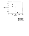
- FIG. 18 is a graph showing the carbon amount [wt%] in a plurality of permanent magnets manufactured by changing the calcination temperature conditions for the permanent magnets of Example 5 and Comparative Examples 3 and 4.
- FIG. 18 shows the result of maintaining the supply amounts of hydrogen and helium during calcination at 1 L / min for 3 hours. As shown in FIG. 18, it can be seen that the amount of carbon in the magnet particles can be greatly reduced when calcined in a hydrogen atmosphere as compared with calcining in a He atmosphere or a vacuum atmosphere. Also, from FIG.
- the carbon content is greatly reduced if the calcining temperature at the time of calcining the magnet powder in a hydrogen atmosphere is increased, and in particular, the carbon content is 0.15 wt. It can be seen that it is possible to make the value less than or equal to%.
- the coarsely pulverized magnet powder is converted into M- (OR) x (where M is V, Mo, Zr, Ta , Ti, W or Nb, R is a hydrocarbon substituent, which may be linear or branched, and x is an arbitrary integer.)
- M is V, Mo, Zr, Ta , Ti, W or Nb
- R is a hydrocarbon substituent, which may be linear or branched
- x is an arbitrary integer.
- the organometallic compound is uniformly attached to the surfaces of the magnet particles.
- the green compact is subjected to a calcining treatment in hydrogen by holding it in a hydrogen atmosphere at 200 ° C. to 900 ° C. for several hours.
- the permanent magnet 1 is manufactured by performing vacuum sintering or pressure sintering.
- the magnet powder or molded body can be produced in a hydrogen atmosphere.
- the thermal decomposition of the organometallic compound can be more easily performed on the entire magnet powder or the entire compact.
- the step of calcining the compact or the magnet powder is performed by holding the compact for a predetermined time in a temperature range of 200 ° C. to 900 ° C., more preferably 400 ° C. to 900 ° C.
- the amount of carbon remaining in the magnet after sintering is 0.15 wt% or less, more preferably 0.1 wt% or less, so that no voids are formed between the main phase of the magnet and the grain boundary phase, and It becomes possible to make the whole magnet into a densely sintered state, and it is possible to prevent the residual magnetic flux density from being lowered. Further, a large number of ⁇ Fe is not precipitated in the main phase of the magnet after sintering, and the magnet characteristics are not greatly deteriorated.
- M- (OR) x (wherein M is V, Mo, Zr, Ta, Ti, W or Nb with respect to the magnet powder. R is a substituent composed of a hydrocarbon. And x is an arbitrary integer.)
- the grain growth of magnet particles during sintering can be suppressed, and after sintering, the exchange interaction between the crystal particles is interrupted to prevent the magnetization reversal of each crystal particle and improve the magnetic performance. It becomes possible to make it. Further, decarbonization can be easily performed as compared with the case where other organometallic compounds are added, and there is no possibility that the coercive force is reduced by the carbon contained in the sintered magnet. The whole can be sintered precisely.
- Nb or the like which is a high melting point metal
- Nb or the like which is a high melting point metal
- Nb or the like that is unevenly distributed at the grain boundaries suppresses the grain growth of the magnet particles during sintering, and the crystals after sintering By breaking the exchange interaction between particles, it is possible to prevent the magnetization reversal of each crystal particle and improve the magnetic performance.
- the addition amount of Nb etc. is small compared with the past, the fall of a residual magnetic flux density can be suppressed.
- the powdered magnet particles are calcined, the remaining organic compound is thermally decomposed as compared with the case of calcining the molded magnet particles.
- this invention is not limited to the said Example, Of course, various improvement and deformation
- the pulverization conditions, kneading conditions, calcination conditions, dehydrogenation conditions, sintering conditions, etc. of the magnet powder are not limited to the conditions described in the above examples. Further, the dehydrogenation step may be omitted.
- the wet bead mill is used as a means for wet pulverizing the magnet powder, but other wet pulverization methods may be used.
- a nanomizer or the like may be used.
- niobium ethoxide, niobium n-propoxide, niobium n-butoxide and niobium n-hexoxide are used as organometallic compounds containing Nb and the like added to the magnet powder, but M- ( OR) x (wherein M is V, Mo, Zr, Ta, Ti, W or Nb. R is a substituent composed of hydrocarbon, which may be linear or branched. X is an arbitrary integer.
- organometallic compounds may be used as long as they are organometallic compounds represented by For example, an organometallic compound composed of an alkyl group having 7 or more carbon atoms or an organometallic compound composed of a substituent composed of a hydrocarbon other than an alkyl group may be used.
Landscapes
- Engineering & Computer Science (AREA)
- Power Engineering (AREA)
- Chemical & Material Sciences (AREA)
- Materials Engineering (AREA)
- Mechanical Engineering (AREA)
- Metallurgy (AREA)
- Organic Chemistry (AREA)
- Manufacturing & Machinery (AREA)
- Crystallography & Structural Chemistry (AREA)
- Inorganic Chemistry (AREA)
- Hard Magnetic Materials (AREA)
- Powder Metallurgy (AREA)
- Manufacturing Cores, Coils, And Magnets (AREA)
Priority Applications (4)
| Application Number | Priority Date | Filing Date | Title |
|---|---|---|---|
| US13/499,616 US9039920B2 (en) | 2010-03-31 | 2011-03-28 | Permanent magnet and manufacturing method thereof |
| EP11765492.1A EP2506274B1 (en) | 2010-03-31 | 2011-03-28 | Manufacturing method for permanent magnet |
| KR1020127007180A KR101189936B1 (ko) | 2010-03-31 | 2011-03-28 | 영구 자석 및 영구 자석의 제조 방법 |
| CN2011800039928A CN102687217A (zh) | 2010-03-31 | 2011-03-28 | 永久磁铁及永久磁铁的制造方法 |
Applications Claiming Priority (2)
| Application Number | Priority Date | Filing Date | Title |
|---|---|---|---|
| JP2010-084470 | 2010-03-31 | ||
| JP2010084470 | 2010-03-31 |
Publications (1)
| Publication Number | Publication Date |
|---|---|
| WO2011125592A1 true WO2011125592A1 (ja) | 2011-10-13 |
Family
ID=44762541
Family Applications (1)
| Application Number | Title | Priority Date | Filing Date |
|---|---|---|---|
| PCT/JP2011/057573 Ceased WO2011125592A1 (ja) | 2010-03-31 | 2011-03-28 | 永久磁石及び永久磁石の製造方法 |
Country Status (7)
| Country | Link |
|---|---|
| US (1) | US9039920B2 (enExample) |
| EP (1) | EP2506274B1 (enExample) |
| JP (2) | JP4923153B2 (enExample) |
| KR (1) | KR101189936B1 (enExample) |
| CN (1) | CN102687217A (enExample) |
| TW (2) | TW201218221A (enExample) |
| WO (1) | WO2011125592A1 (enExample) |
Cited By (2)
| Publication number | Priority date | Publication date | Assignee | Title |
|---|---|---|---|---|
| WO2013047467A1 (ja) * | 2011-09-30 | 2013-04-04 | 日東電工株式会社 | 希土類永久磁石及び希土類永久磁石の製造方法 |
| WO2013047469A1 (ja) * | 2011-09-30 | 2013-04-04 | 日東電工株式会社 | 永久磁石及び永久磁石の製造方法 |
Families Citing this family (8)
| Publication number | Priority date | Publication date | Assignee | Title |
|---|---|---|---|---|
| EP2503562B1 (en) * | 2010-03-31 | 2014-07-02 | Nitto Denko Corporation | Manufacturing method for permanent magnet |
| JP4923151B2 (ja) * | 2010-03-31 | 2012-04-25 | 日東電工株式会社 | 永久磁石及び永久磁石の製造方法 |
| JP4865100B2 (ja) * | 2010-03-31 | 2012-02-01 | 日東電工株式会社 | 永久磁石及び永久磁石の製造方法 |
| KR101189856B1 (ko) * | 2010-03-31 | 2012-10-10 | 닛토덴코 가부시키가이샤 | 영구 자석 및 영구 자석의 제조 방법 |
| WO2011125595A1 (ja) * | 2010-03-31 | 2011-10-13 | 日東電工株式会社 | 永久磁石及び永久磁石の製造方法 |
| JP5011420B2 (ja) * | 2010-05-14 | 2012-08-29 | 日東電工株式会社 | 永久磁石及び永久磁石の製造方法 |
| JP2013191607A (ja) * | 2012-03-12 | 2013-09-26 | Nitto Denko Corp | 希土類永久磁石及び希土類永久磁石の製造方法 |
| JP2013191616A (ja) * | 2012-03-12 | 2013-09-26 | Nitto Denko Corp | 希土類永久磁石及び希土類永久磁石の製造方法 |
Citations (4)
| Publication number | Priority date | Publication date | Assignee | Title |
|---|---|---|---|---|
| JPH1064746A (ja) * | 1996-08-23 | 1998-03-06 | Sumitomo Special Metals Co Ltd | 薄肉R−Fe−B系焼結磁石の製造方法 |
| JP3298219B2 (ja) | 1993-03-17 | 2002-07-02 | 日立金属株式会社 | 希土類―Fe−Co−Al−V−Ga−B系焼結磁石 |
| JP2009224671A (ja) * | 2008-03-18 | 2009-10-01 | Nitto Denko Corp | 永久磁石及び永久磁石の製造方法 |
| JP2009259956A (ja) * | 2008-04-15 | 2009-11-05 | Nitto Denko Corp | 永久磁石及び永久磁石の製造方法 |
Family Cites Families (6)
| Publication number | Priority date | Publication date | Assignee | Title |
|---|---|---|---|---|
| JP2004281873A (ja) * | 2003-03-18 | 2004-10-07 | Hitachi Metals Ltd | 希土類磁石の製造方法 |
| JP4525072B2 (ja) | 2003-12-22 | 2010-08-18 | 日産自動車株式会社 | 希土類磁石およびその製造方法 |
| JP4635832B2 (ja) | 2005-11-08 | 2011-02-23 | 日立金属株式会社 | 希土類焼結磁石の製造方法 |
| EP2503562B1 (en) * | 2010-03-31 | 2014-07-02 | Nitto Denko Corporation | Manufacturing method for permanent magnet |
| JP4923151B2 (ja) * | 2010-03-31 | 2012-04-25 | 日東電工株式会社 | 永久磁石及び永久磁石の製造方法 |
| KR101189856B1 (ko) * | 2010-03-31 | 2012-10-10 | 닛토덴코 가부시키가이샤 | 영구 자석 및 영구 자석의 제조 방법 |
-
2011
- 2011-03-28 KR KR1020127007180A patent/KR101189936B1/ko not_active Expired - Fee Related
- 2011-03-28 EP EP11765492.1A patent/EP2506274B1/en not_active Not-in-force
- 2011-03-28 US US13/499,616 patent/US9039920B2/en not_active Expired - Fee Related
- 2011-03-28 WO PCT/JP2011/057573 patent/WO2011125592A1/ja not_active Ceased
- 2011-03-28 CN CN2011800039928A patent/CN102687217A/zh active Pending
- 2011-03-28 JP JP2011069075A patent/JP4923153B2/ja not_active Expired - Fee Related
- 2011-03-31 TW TW100111449A patent/TW201218221A/zh not_active IP Right Cessation
- 2011-03-31 TW TW101116560A patent/TW201239915A/zh not_active IP Right Cessation
- 2011-12-22 JP JP2011281575A patent/JP4923164B1/ja not_active Expired - Fee Related
Patent Citations (4)
| Publication number | Priority date | Publication date | Assignee | Title |
|---|---|---|---|---|
| JP3298219B2 (ja) | 1993-03-17 | 2002-07-02 | 日立金属株式会社 | 希土類―Fe−Co−Al−V−Ga−B系焼結磁石 |
| JPH1064746A (ja) * | 1996-08-23 | 1998-03-06 | Sumitomo Special Metals Co Ltd | 薄肉R−Fe−B系焼結磁石の製造方法 |
| JP2009224671A (ja) * | 2008-03-18 | 2009-10-01 | Nitto Denko Corp | 永久磁石及び永久磁石の製造方法 |
| JP2009259956A (ja) * | 2008-04-15 | 2009-11-05 | Nitto Denko Corp | 永久磁石及び永久磁石の製造方法 |
Non-Patent Citations (1)
| Title |
|---|
| See also references of EP2506274A4 * |
Cited By (2)
| Publication number | Priority date | Publication date | Assignee | Title |
|---|---|---|---|---|
| WO2013047467A1 (ja) * | 2011-09-30 | 2013-04-04 | 日東電工株式会社 | 希土類永久磁石及び希土類永久磁石の製造方法 |
| WO2013047469A1 (ja) * | 2011-09-30 | 2013-04-04 | 日東電工株式会社 | 永久磁石及び永久磁石の製造方法 |
Also Published As
| Publication number | Publication date |
|---|---|
| KR20120049353A (ko) | 2012-05-16 |
| TWI374459B (enExample) | 2012-10-11 |
| US9039920B2 (en) | 2015-05-26 |
| TWI379321B (enExample) | 2012-12-11 |
| EP2506274B1 (en) | 2014-07-02 |
| EP2506274A4 (en) | 2013-01-23 |
| TW201218221A (en) | 2012-05-01 |
| JP4923164B1 (ja) | 2012-04-25 |
| US20120187328A1 (en) | 2012-07-26 |
| JP2011228667A (ja) | 2011-11-10 |
| JP4923153B2 (ja) | 2012-04-25 |
| KR101189936B1 (ko) | 2012-10-12 |
| CN102687217A (zh) | 2012-09-19 |
| TW201239915A (en) | 2012-10-01 |
| JP2012124496A (ja) | 2012-06-28 |
| EP2506274A1 (en) | 2012-10-03 |
Similar Documents
| Publication | Publication Date | Title |
|---|---|---|
| JP4923164B1 (ja) | 永久磁石及び永久磁石の製造方法 | |
| JP4923152B2 (ja) | 永久磁石及び永久磁石の製造方法 | |
| JP4865100B2 (ja) | 永久磁石及び永久磁石の製造方法 | |
| JP4923148B2 (ja) | 永久磁石及び永久磁石の製造方法 | |
| JP4865920B2 (ja) | 永久磁石及び永久磁石の製造方法 | |
| JP4865098B2 (ja) | 永久磁石及び永久磁石の製造方法 | |
| JP4923151B2 (ja) | 永久磁石及び永久磁石の製造方法 | |
| JP4923147B2 (ja) | 永久磁石及び永久磁石の製造方法 | |
| JP4865097B2 (ja) | 永久磁石及び永久磁石の製造方法 | |
| JP4865099B2 (ja) | 永久磁石及び永久磁石の製造方法 | |
| JP5908247B2 (ja) | 永久磁石の製造方法 | |
| JP4923150B2 (ja) | 永久磁石及び永久磁石の製造方法 | |
| WO2011125590A1 (ja) | 永久磁石及び永久磁石の製造方法 | |
| JP5501830B2 (ja) | 永久磁石及び永久磁石の製造方法 | |
| JP5453154B2 (ja) | 永久磁石及び永久磁石の製造方法 | |
| JP2011216732A (ja) | 永久磁石及び永久磁石の製造方法 | |
| JP2011216724A (ja) | 永久磁石及び永久磁石の製造方法 |
Legal Events
| Date | Code | Title | Description |
|---|---|---|---|
| WWE | Wipo information: entry into national phase |
Ref document number: 201180003992.8 Country of ref document: CN |
|
| 121 | Ep: the epo has been informed by wipo that ep was designated in this application |
Ref document number: 11765492 Country of ref document: EP Kind code of ref document: A1 |
|
| ENP | Entry into the national phase |
Ref document number: 20127007180 Country of ref document: KR Kind code of ref document: A |
|
| WWE | Wipo information: entry into national phase |
Ref document number: 2867/CHENP/2012 Country of ref document: IN Ref document number: 2011765492 Country of ref document: EP |
|
| WWE | Wipo information: entry into national phase |
Ref document number: 13499616 Country of ref document: US |
|
| NENP | Non-entry into the national phase |
Ref country code: DE |