WO2011125542A1 - リターダの制御装置、リターダの制御方法およびリターダの制御装置を有する車両 - Google Patents
リターダの制御装置、リターダの制御方法およびリターダの制御装置を有する車両 Download PDFInfo
- Publication number
- WO2011125542A1 WO2011125542A1 PCT/JP2011/057328 JP2011057328W WO2011125542A1 WO 2011125542 A1 WO2011125542 A1 WO 2011125542A1 JP 2011057328 W JP2011057328 W JP 2011057328W WO 2011125542 A1 WO2011125542 A1 WO 2011125542A1
- Authority
- WO
- WIPO (PCT)
- Prior art keywords
- retarder
- temperature
- rotation speed
- heat dissipation
- energy
- Prior art date
- Legal status (The legal status is an assumption and is not a legal conclusion. Google has not performed a legal analysis and makes no representation as to the accuracy of the status listed.)
- Ceased
Links
Images

Classifications
-
- H—ELECTRICITY
- H02—GENERATION; CONVERSION OR DISTRIBUTION OF ELECTRIC POWER
- H02P—CONTROL OR REGULATION OF ELECTRIC MOTORS, ELECTRIC GENERATORS OR DYNAMO-ELECTRIC CONVERTERS; CONTROLLING TRANSFORMERS, REACTORS OR CHOKE COILS
- H02P15/00—Arrangements for controlling dynamo-electric brakes or clutches
-
- H—ELECTRICITY
- H02—GENERATION; CONVERSION OR DISTRIBUTION OF ELECTRIC POWER
- H02K—DYNAMO-ELECTRIC MACHINES
- H02K49/00—Dynamo-electric clutches; Dynamo-electric brakes
- H02K49/02—Dynamo-electric clutches; Dynamo-electric brakes of the asynchronous induction type
-
- H—ELECTRICITY
- H02—GENERATION; CONVERSION OR DISTRIBUTION OF ELECTRIC POWER
- H02K—DYNAMO-ELECTRIC MACHINES
- H02K49/00—Dynamo-electric clutches; Dynamo-electric brakes
- H02K49/02—Dynamo-electric clutches; Dynamo-electric brakes of the asynchronous induction type
- H02K49/04—Dynamo-electric clutches; Dynamo-electric brakes of the asynchronous induction type of the eddy-current hysteresis type
- H02K49/043—Dynamo-electric clutches; Dynamo-electric brakes of the asynchronous induction type of the eddy-current hysteresis type with a radial airgap
-
- H—ELECTRICITY
- H02—GENERATION; CONVERSION OR DISTRIBUTION OF ELECTRIC POWER
- H02K—DYNAMO-ELECTRIC MACHINES
- H02K49/00—Dynamo-electric clutches; Dynamo-electric brakes
- H02K49/10—Dynamo-electric clutches; Dynamo-electric brakes of the permanent-magnet type
-
- H—ELECTRICITY
- H02—GENERATION; CONVERSION OR DISTRIBUTION OF ELECTRIC POWER
- H02K—DYNAMO-ELECTRIC MACHINES
- H02K9/00—Arrangements for cooling or ventilating
- H02K9/02—Arrangements for cooling or ventilating by ambient air flowing through the machine
-
- H—ELECTRICITY
- H02—GENERATION; CONVERSION OR DISTRIBUTION OF ELECTRIC POWER
- H02K—DYNAMO-ELECTRIC MACHINES
- H02K21/00—Synchronous motors having permanent magnets; Synchronous generators having permanent magnets
- H02K21/02—Details
- H02K21/021—Means for mechanical adjustment of the excitation flux
- H02K21/028—Means for mechanical adjustment of the excitation flux by modifying the magnetic circuit within the field or the armature, e.g. by using shunts, by adjusting the magnets position, by vectorial combination of field or armature sections
-
- H—ELECTRICITY
- H02—GENERATION; CONVERSION OR DISTRIBUTION OF ELECTRIC POWER
- H02K—DYNAMO-ELECTRIC MACHINES
- H02K2213/00—Specific aspects, not otherwise provided for and not covered by codes H02K2201/00 - H02K2211/00
- H02K2213/09—Machines characterised by the presence of elements which are subject to variation, e.g. adjustable bearings, reconfigurable windings, variable pitch ventilators
Definitions
- the present invention relates to a retarder control device, a retarder control method, and a vehicle having a retarder control device.
- the exhaust brake and retarder which are auxiliary brakes, are used to perform stable deceleration when descending on long slopes and to prevent the foot brake from burning out. Has been.
- This retarder may overheat if used continuously. Therefore, in order to prevent this overheating, a temperature sensor is provided in the heat dissipating means for dissipating the heat energy, and the operation of the retarder is stopped when the temperature detected by the temperature sensor reaches a predetermined temperature or more. (See Patent Document 1).
- the heat generation amount of the rotor is calculated from the rotation speed and torque
- the heat release amount is calculated from the ambient temperature and heat capacity of the rotor
- the rotor temperature is estimated from the difference between the heat generation amount and the heat release amount and the heat release time constant.
- the rotor temperature change compensation signal is output using the torque / excitation current ratio characteristic with respect to the rotor temperature
- the rotation speed compensation signal is output using the torque / excitation current ratio characteristic with respect to the rotation speed.
- the control gain is adjusted based on each compensation signal.
- JP-A-10-136636 (abstract) JP-A-8-275597
- Patent Document 1 stops its operation when it reaches a predetermined temperature, so that it cannot fully function as an auxiliary brake.
- the predetermined temperature at which the retarder operation is stopped varies depending on the specification of the vehicle model or the like, it is necessary to provide a predetermined temperature for each specification and to provide a plurality of product numbers of ECU (Electric Control Unit).
- the retarder disclosed in Patent Document 2 can determine torque characteristics in a wide rotor temperature range and rotation speed range, but calculates the amount of heat generated by the rotor from the rotation speed and torque, and from the ambient temperature and heat capacity of the rotor. Calculates the amount of heat dissipation, calculates the rotor temperature from the difference between the amount of heat generation and the amount of heat dissipation and the heat dissipation time constant, outputs the compensation signal for the rotor temperature change using the ratio of the torque to the rotor temperature and the excitation current, Control means for performing extremely complicated operations such as outputting a rotational speed compensation signal using the characteristics of the excitation current ratio and adjusting the control gain based on each compensation signal is required. This cannot be applied to a control means with a simple configuration that is controlled by a relay that closes the power supply circuit by the output of the temperature sensor, like the retarder disclosed in Patent Document 1.
- the present invention has been made in view of such a problem, and an object of the present invention is to make it possible to sufficiently function as an auxiliary brake regardless of traveling conditions and to make the ECU common by simple control. It is an object of the present invention to provide a retarder control device, a retarder control method, and a vehicle having the retarder control device.
- an aspect of the present invention provides a retarder having energy conversion means that converts rotational energy into electrical energy, and heat dissipation means that converts the electrical energy into heat energy and dissipates heat, and heat dissipation.
- Temperature detection means for detecting the temperature of the means, rotation speed detection means for detecting the rotation speed of the heat radiating means, and generation of electrical energy when the temperature detected by the temperature detection means indicates a temperature exceeding a predetermined threshold.
- control unit for controlling the retarder, wherein the control unit variably sets a predetermined threshold corresponding to the rotation speed of the heat radiating means, and the heat radiating means detected by the temperature detecting means The generation of electrical energy is reduced when the temperature exceeds a predetermined threshold corresponding to the rotational speed of the heat dissipating means detected by the rotational speed detecting means. And performs control to.
- the generation of electric energy is reduced and the braking force is maximized compared to the first state and the first state. It is preferable to switch between the three states, the second state where the braking force is weak and the third state where the braking force is not generated.
- the temperature of the heat dissipating means detected by the temperature detecting means is a temperature exceeding a predetermined threshold, it is preferable that switching is performed such that the generation of electric energy is reduced and the braking force by the retarder is reduced by one step. .
- a retarder control method comprising: energy conversion means for converting rotational energy into electrical energy; and heat dissipation means for converting the electrical energy into heat energy to dissipate heat. Detects the temperature of the heat dissipation means, detects the rotation speed of the heat dissipation means by the rotation speed detection means, outputs a predetermined temperature threshold corresponding to the rotation speed from the rotation speed detected by the rotation speed detection means, and detects the temperature When the temperature detected by the means exceeds the threshold, the generation of electrical energy is reduced.
- the vehicle has a retarder control device.
- the function as an auxiliary brake of the retarder can be sufficiently exerted by simple control regardless of the driving condition, and the ECU can be shared.
- FIG. 1 It is the schematic which shows the structure of the control apparatus of the retarder which concerns on one embodiment of this invention. It is a perspective view which shows partially the structure of the energy conversion means in FIG. It is a perspective view which shows the structure of the rotating yoke body in FIG. It is a figure which shows the positional relationship of a rotation yoke body and a pole piece when the retarder in FIG. 1 exists in the state of HIGH. It is a figure which shows the positional relationship of a rotation yoke body and a pole piece when the retarder in FIG. 1 is in an OFF state. It is a figure which shows the positional relationship of a rotation yoke body and a pole piece when the retarder in FIG. 1 exists in a LOW state.
- FIG. 7 It is a figure which shows the threshold value (L2) which has a constant value irrespective of the drum temperature threshold value (L1) used when changing a retarder from HIGH to LOW or LOW to OFF, and the rotational speed of a drum. Transition of vehicle deceleration (L11) from the start of braking when the threshold (L1) shown in FIG. 7 is used, and Transition of vehicle deceleration (L12) from the start of braking when using the threshold (L2) FIG.
- a retarder control apparatus 1 according to an embodiment of the present invention will be described with reference to the drawings.
- a state in which a large braking force is exerted by the retarder 2 is denoted as HIGH, and a state in which a braking force smaller than the HIGH state is exhibited by the retarder 2 is denoted as LOW.
- a state in which the braking force is not exerted by the retarder 2 is expressed as OFF.
- FIG. 1 is a schematic diagram showing a configuration of a retarder control device 1 according to an embodiment of the present invention.
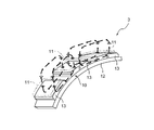
- FIG. 2 is a perspective view partially showing the configuration of the energy conversion means 3 in FIG.
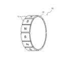
- FIG. 3 is a perspective view showing the configuration of the rotating yoke body 10 in FIG.
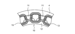
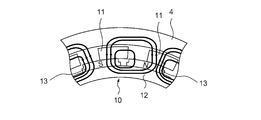
- FIG. 4 is a diagram showing a positional relationship between the rotary yoke body 10 and the pole piece 11 when the retarder 2 in FIG. 1 is in a HIGH state.
- FIG. 5 is a diagram showing a positional relationship between the rotary yoke body 10 and the pole piece 11 when the retarder 2 in FIG. 1 is in an OFF state.
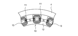
- FIG. 6 is a diagram showing the positional relationship between the rotary yoke body 10 and the pole piece 11 when the retarder 2 in FIG. 1 is in the LOW state.
- a retarder control device 1 according to an embodiment of the present invention (hereinafter referred to as a retarder control device 1) is a retarder for sufficiently exerting a braking force of a retarder 2 as an example of an auxiliary brake provided in a vehicle. 2 is a device for controlling the operation of 2.
- the retarder control device 1 includes a retarder 2 including an energy conversion means 3 for converting rotational energy into electric energy, and a drum 4 as an example of a heat radiating means for converting the electric energy into heat energy and radiating heat, A temperature sensor 5 as an example of temperature detecting means for detecting the temperature of the drum 4, a rotational speed detecting means 6 for detecting the rotational speed of the drum 4, and the retarder 2 based on the detected values of the temperature and rotational speed of the drum 4. It has the control part 7 which controls braking force, and the retarder operation part 9 for switching the state of the retarder 2 by operation of an operator.
- the temperature detection means for example, a means for estimating the temperature of the drum 4 from the energy absorbed by the retarder 2 may be employed instead of the temperature sensor 5 that directly detects the temperature of the drum 4.
- the rotational speed detecting means 6 may be a means for estimating the rotational speed of the propeller shaft from the engine rotational speed and the gear ratio.
- the drum 4 has a ring shape, and the drum 4 is disposed outside the energy conversion means 3 in a rotatable form.
- the energy conversion means 3 includes a rotating yoke body 10 having a substantially ring shape and a pole piece 11 disposed on the outer peripheral side of the rotating yoke body 10.
- the rotating yoke body 10 is arranged in a form that can rotate relative to the pole piece 11.
- the rotating yoke body 10 has a plurality (for example, 12 pieces) of N-pole and S-pole permanent magnets 13 arranged alternately on the outer periphery of a yoke 12 having a ring shape. Consists of. As shown in FIG.
- the retarder 2 is provided with a first cylinder 14 and a second cylinder 15 for driving the rotary yoke body 10 in the circumferential direction.
- Air from the air tank 18 is supplied to the first cylinder 14 and the second cylinder 15 based on opening and closing of the first electromagnetic valve 16 and the second electromagnetic valve 17.
- the first electromagnetic valve 16 and the second electromagnetic valve 17 are connected to an air tank 18 via a three-way valve 20. Therefore, the air sent from the air tank 18 passes through the first electromagnetic valve 16 or the second electromagnetic valve 17 via the three-way valve 20 and is supplied to the first cylinder 14 and the second cylinder 15. .
- a valve 21 is provided on the bottom 14a side of the first cylinder 14, and this valve 21 is connected to a connecting portion 15c provided on the bottom 15a side of the second cylinder 15 via a tube.
- a valve 22 is disposed on the side of the first cylinder 14 where the rod 14b protrudes. This valve 22 is connected via a tube to a connecting portion 15d provided on the side of the second cylinder 15 where the rod 15b protrudes.
- the first electromagnetic valve 16 and the valve 22 are connected via a tube, and the second electromagnetic valve 17 and the valve 21 are connected via a tube.
- the tips of the rods 14b and 15b of the first cylinder 14 and the second cylinder 15 are connected to the rotary yoke body 10, respectively.
- the air in the air tank 18 passes through the second electromagnetic valve 17 and is supplied to the valve 21, the air sent into the valve 21 is supplied from the bottom 14 a side to the inside of the first cylinder 14, and the valve 21 to the connection portion 15c.
- the air supplied to the connection part 15c is supplied to the inside of the 2nd cylinder 15 from the bottom part 15a side. Then, the pistons 14e and 15e move toward the rods 14b and 15b, so that the rods 14b and 15b are pushed up, and the rotary yoke body 10 moves in the clockwise direction in FIG.
- the rotating yoke body 10 of the retarder 2 is configured to be rotatable at a rotation angle corresponding to 1 ⁇ 2 of the dimension along the circumferential direction of the permanent magnet 13 in the circumferential direction.
- the retarder 2 serving as the auxiliary brake is changed into three states of HIGH, which is an example of the first state, LOW, which is an example of the second state, and OFF, which is an example of the third state.
- Switching of the retarder 2 to the HIGH, LOW, and OFF states can be performed by the operation of the retarder operation unit 9 by the operator and can be performed by the control of the control unit 7.
- the magnetic field generated from the permanent magnet 13 is It is shielded by the piece 11. That is, even if the drum 4 rotates in this state, no eddy current (inductive current) is generated in the drum 4, so that no force (braking force) that hinders the rotation of the drum 4 is generated.
- the rotary yoke body 10 is rotated by a predetermined rotation angle, and as shown in FIG. 6, one end of the permanent magnet 13 is hung on the pole piece 11, but the other end is held at a position not hung on the pole piece 11. If it does, the magnetic field which the permanent magnet 13 generate
- the state shown in FIG. 4 in which the force (braking force) that hinders the rotation of the drum 4 is the largest is the HIGH state
- the state shown in FIG. 6 in which a weak braking force is generated compared to the HIGH state is the LOW state.
- the state shown in FIG. 5 in which no braking force is generated is an OFF state.
- the three states of HIGH, LOW, and OFF of the retarder 2 are switched by the operation of the retarder operation unit 9 and the control of the control unit 7.
- the switching of the retarder 2 by the retarder operation unit 9 will be described. Switching of the retarder 2 by the retarder operation unit 9 is performed when the operator manually switches the retarder operation unit 9 provided in the vehicle to one of HIGH, LOW, and OFF.
- the signal is transmitted to the control unit 7, and the first electromagnetic valve 16 is based on the signal received by the control unit 7 from the retarder operation unit 9.
- the 2nd solenoid valve 17 is opened and closed. Air is supplied to the first cylinder 14 and the second cylinder 15 by opening and closing the first solenoid valve 16 or the second solenoid valve 17, and the rods 14b and 15b move forward or backward based on the supply of the air. .
- the rods 14b and 15b move, the rotary yoke body 10 moves in the circumferential direction, and the retarder 2 is switched.
- the control unit 7 receives a signal from the retarder operation unit 9 and closes the first electromagnetic valve 16.
- the second electromagnetic valve 17 is operated to be opened while being operated.
- air from the air tank 18 is supplied to the second electromagnetic valve 17 via the three-way valve 20.
- the air supplied to the second electromagnetic valve 17 is sent out from the second electromagnetic valve 17 toward the valve 21.
- the air sent to the valve 21 is supplied from the bottom 14 a side to the inside of the first cylinder 14 and is supplied to the connection portion 15 c of the second cylinder 15 through the valve 21.
- the air supplied to the connection portion 15c is supplied into the second cylinder 15 from the bottom portion 15a side.
- the control unit 7 receives a signal from the retarder operation unit 9 and opens the first electromagnetic valve 16. And the second electromagnetic valve 17 is operated in a closed state. Then, air from the air tank 18 is supplied to the first electromagnetic valve 16 via the three-way valve 20. Then, the air supplied to the first electromagnetic valve 16 is sent out from the first electromagnetic valve 16 toward the valve 22.
- the air sent to the valve 22 is supplied from the rod 14 b side to the inside of the first cylinder 14 and supplied to the connecting portion 15 d of the second cylinder 15 through the valve 22.
- the air supplied to the connecting portion 15d is supplied into the second cylinder 15 from the rod 15b side.
- the switching of the retarder 2 based on the control of the control unit 7 is performed based on the temperature of the drum 4 detected by the temperature sensor 5 and the rotational speed of the drum 4 detected by the rotational speed detection means 6. Specifically, when the detected temperature of the drum 4 exceeds a predetermined temperature (threshold value) set for the detected rotation speed, the retarder 2 is switched from HIGH to LOW or from LOW to OFF. That is, when the temperature of the drum 4 detected by the temperature sensor 5 exceeds a predetermined threshold value corresponding to the rotational speed of the drum 4 detected by the rotational speed detection means 6, the braking force generated in the drum 4 is set to 1. Switching is made to lower the level.
- a predetermined temperature threshold value
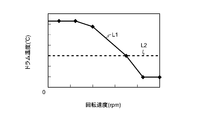
- FIG. 7 is a diagram showing a drum temperature threshold (L1) used when switching the retarder 2 from HIGH to LOW or LOW to OFF, and a threshold (L2) having a constant value regardless of the rotational speed of the drum 4. .
- the drum temperature threshold (L1) corresponds to the rotational speed of the drum 4.
- the threshold value is set to a high temperature in a range where the rotational speed is relatively low, and further, the threshold value is set to decrease as the rotational speed increases.
- the threshold value is set to a low temperature in a range where the rotational speed is relatively high.
- the temperature of the drum 4 rapidly increases when the rotation speed of the drum 4 is high, the temperature continues to increase even after switching. For this reason, in order to prevent the drum 4 from becoming high temperature in a range where the rotational speed is high, the temperature is set to a relatively low temperature.
- the threshold when the rotational speed of the drum 4 is relatively low is a high temperature. That is, when the rotation speed of the drum 4 is relatively low, when the temperature of the drum 4 reaches a high temperature which is a threshold value, the control unit 7 controls the retarder 2 to be switched from HIGH to LOW.
- the control unit 7 that has received the detection values from the temperature sensor 5 and the rotation speed detection means 6 sets the received temperature and rotation speed detection values and the temperature threshold for the rotation speed shown in FIG. This is done by comparing. Specifically, the control unit 7 compares the detected value received from the temperature sensor 5 with the threshold value corresponding to the rotational speed detected by the rotational speed detecting means 6, and as a result, the detected temperature is detected. When the threshold value corresponding to the speed is exceeded, the braking force generated in the retarder 2 is decreased by one step from the control unit 7 toward the retarder 2 (the first electromagnetic valve 16 and the second electromagnetic valve 17). A control signal for switching is transmitted. That is, a control signal for switching the retarder 2 from HIGH to LOW or from LOW to OFF is transmitted.
- a control signal for opening the first electromagnetic valve 16 is transmitted from the control unit 7 to the first electromagnetic valve 16. Then, the first electromagnetic valve 16 opens, and the air in the air tank 18 passes through the three-way valve 20 and the first electromagnetic valve 16 and is supplied to the valve 22 as described above.
- the air supplied to the valve 22 is supplied from the rod 14b side to the inside of the first cylinder 14 and supplied from the rod 15b side to the inside of the second cylinder 15 through the connecting portion 15d.
- piston 14e, 15e moves to the direction which pushes down rod 14b, 15b, and rod 14b, 15b retracts.
- the rotating yoke body 10 moves counterclockwise, and the retarder 2 is, for example, in a HIGH state so that it changes from the HIGH state shown in FIG. 4 to the LOW state shown in FIG. Then, switching is performed so that the braking force generated in the retarder 2 is lowered by one step.
- the retarder control device 1 since the temperature (threshold value) for switching the retarder 2 is made variable with respect to the rotational speed, the retarder 2 can be appropriately controlled for each traveling condition. It becomes possible.
- the threshold value is set in consideration of the rising speed. Even if the state of the retarder 2 is lowered to LOW or OFF, the drum 4 does not reach the limit temperature. Accordingly, when the rotational speed of the drum 4 is relatively low as in the threshold value (L1) shown in FIG. 7, a strong and strong braking force is applied for a long time by setting the threshold value to a high temperature. be able to. As a result, the deceleration performance of the retarder 2 can be improved.
- Such control based on the temperature threshold can also be applied to simple control means for closing the power supply circuit based on the output of the temperature sensor, such as a retarder disclosed in Patent Document 1.
- FIG. 8 shows the transition (L11) of the deceleration of the vehicle from the start of braking when the threshold (L1) shown in FIG. 7 is used, and the deceleration of the vehicle from the start of braking when the threshold (L2) is used. It is a figure which shows transition (L12).
- the threshold temperature (L2) is used, whereas the limit temperature is not reached even if the retarder 4 is lowered to LOW or OFF.
- the temperature reaches a relatively low temperature, it is switched to the LOW or OFF state. That is, as shown in FIG. 8, when the threshold value (L2) is used, the retarder 2 is inferior in deceleration performance compared to the case where the threshold value (L1) is used.
- the retarder 4 in the deceleration transition (L12), the retarder 4 is switched to LOW or OFF after a relatively short time has elapsed since the start of braking.
- the deceleration transition (L11) the state of the retarder 4 is maintained at HIGH or LOW until a relatively long time has elapsed since the start of braking.
- the drum 4 When the rotational speed of the drum 4 is relatively high, the temperature rise rate of the drum 4 is fast. Therefore, if the threshold value is not set to a low temperature in consideration of the rise speed, the drum 4 reaches the limit temperature. I can't prevent that. Accordingly, when the rotational speed of the drum 4 is relatively high as in the threshold value (L1) shown in FIG. 7, the drum 4 can be prevented from becoming hot by setting the threshold value to a low temperature. As a result, the life of the retarder 2 can be extended.
- the temperature (threshold value) for switching the retarder 2 is set to be variable with respect to the rotational speed. For this reason, it is not necessary to set the switching temperature for each specification such as the vehicle type as in the case of the threshold value (L2) where the switching temperature is a constant value. Therefore, the ECU can be shared, and as a result, the set product number of the ECU can be reduced.
- switching is performed so that the braking force of the retarder 2 increases by one step when the rotating yoke body 10 moves in the clockwise direction, and when the rotating yoke body 10 moves in the counterclockwise direction.
- the switching is performed so that the braking force of the retarder 2 is lowered by one step, but is not limited to such a configuration.
- the retarder 2 may be switched so that the braking force of the retarder 2 is increased by one step, and the braking force of the retarder 2 may be switched so that the braking force of the retarder 2 is decreased by one step when the rotary yoke body 10 is moved in the clockwise direction.
- switching between the three states of HIGH, LOW, and OFF may be performed.
- the switching temperature (threshold value) of the retarder 2 with respect to the rotation speed is as shown in FIG. 7, but the threshold value is not limited to that shown in FIG. It is good also as a form different from 7.
- both the first solenoid valve 16 and the second solenoid valve 17 are configured to only pump air toward the first cylinder 14 and the second cylinder 15.
- the first solenoid valve 16 and the second solenoid valve 17 pump air to the first cylinder 14 and the second cylinder 15 and suck air from the first cylinder 14 and the second cylinder 15.
- the air may be returned to the air tank 18.
- the process of the control unit 7 is executed by hardware, but the process of the control unit 7 may be executed by software. More specifically, the retarder 2 can be controlled by a program function.
- the threshold value (L1) shown in FIG. 7 is used for switching both HIGH to LOW and LOW to OFF, but the threshold value (L1) shown in FIG. 7 is set to one of HIGH to LOW and LOW to OFF. It may be used only for switching, and another threshold may be used for the remaining other switching.
- a permanent magnet type retarder is used as the retarder 2
- another drive type retarder such as an electromagnetic retarder or a fluid type retarder may be used as the retarder 2.
Landscapes
- Engineering & Computer Science (AREA)
- Power Engineering (AREA)
- Dynamo-Electric Clutches, Dynamo-Electric Brakes (AREA)
- Motor Or Generator Cooling System (AREA)
- Transmission Of Braking Force In Braking Systems (AREA)
Abstract
Description
2…リターダ
3…エネルギ変換手段
4…ドラム(放熱手段)
5…温度センサ(温度検出手段)
6…回転速度検出手段
7…制御部
Claims (5)
- 回転エネルギを電気エネルギに変換するエネルギ変換手段と、この電気エネルギを熱エネルギに変換して放熱する放熱手段と、を有するリターダと、
上記放熱手段の温度を検出する温度検出手段と、
上記放熱手段の回転速度を検出する回転速度検出手段と、
上記温度検出手段によって検出された温度が所定の閾値を越える温度を示すときに、上記電気エネルギの発生を低減させるように制御する制御部と、
を有するリターダの制御装置において、
上記制御部は、上記所定の閾値を、上記放熱手段の回転速度に対応させて可変に設定し、上記温度検出手段によって検出された上記放熱手段の温度が、上記回転速度検出手段によって検出された上記放熱手段の回転速度に対応する上記所定の閾値を超える温度であるときに、上記電気エネルギの発生を低減させる制御を行うことを特徴とするリターダの制御装置。 - 請求項1記載のリターダの制御装置において、
前記温度検出手段によって検出された前記放熱手段の温度が前記所定の閾値を超える温度であるとき、前記電気エネルギの発生が低減されて、制動力が最も大きくなる第1の状態、上記第1の状態に比べて制動力が弱い第2の状態および制動力が発生しない第3の状態の3つの状態の間で切り換えがなされることを特徴とするリターダの制御装置。 - 請求項2記載のリターダの制御装置において、
前記温度検出手段によって検出された前記放熱手段の温度が前記所定の閾値を超える温度であるとき、前記電気エネルギの発生が低減されて、前記リターダによる制動力が1段下がるような切り換えがなされることを特徴とするリターダの制御装置。 - 回転エネルギを電気エネルギに変換するエネルギ変換手段と、この電気エネルギを熱エネルギに変換して放熱する放熱手段と、
を有するリターダの制御方法において、
温度検出手段により上記放熱手段の温度を検出し、
回転速度検出手段により上記放熱手段の回転速度を検出し、
上記回転速度検出手段により検出された回転速度から該回転速度に対応する所定の温度の閾値を出力し、上記温度検出手段によって検出された温度が上記閾値を超える温度であるときに、上記電気エネルギの発生を低減させること特徴とするリターダの制御方法。 - 請求項1から3のいずれか1項記載のリターダの制御装置を有する車両。
Priority Applications (3)
| Application Number | Priority Date | Filing Date | Title |
|---|---|---|---|
| KR1020127028834A KR101423641B1 (ko) | 2010-04-07 | 2011-03-25 | 리타더의 제어장치, 리타더의 제어 방법 및 리타더의 제어장치를 가지는 차량 |
| EP11765443.4A EP2557680A4 (en) | 2010-04-07 | 2011-03-25 | Retarder control device, retarder control method, and vehicle having a retarder control device |
| CN201180017141.9A CN102835022B (zh) | 2010-04-07 | 2011-03-25 | 减速器的控制装置、减速器的控制方法以及具有减速器的控制装置的车辆 |
Applications Claiming Priority (2)
| Application Number | Priority Date | Filing Date | Title |
|---|---|---|---|
| JP2010-088632 | 2010-04-07 | ||
| JP2010088632A JP5606768B2 (ja) | 2010-04-07 | 2010-04-07 | リターダの制御装置、リターダの制御方法およびリターダの制御装置を有する車両 |
Publications (1)
| Publication Number | Publication Date |
|---|---|
| WO2011125542A1 true WO2011125542A1 (ja) | 2011-10-13 |
Family
ID=44762496
Family Applications (1)
| Application Number | Title | Priority Date | Filing Date |
|---|---|---|---|
| PCT/JP2011/057328 Ceased WO2011125542A1 (ja) | 2010-04-07 | 2011-03-25 | リターダの制御装置、リターダの制御方法およびリターダの制御装置を有する車両 |
Country Status (5)
| Country | Link |
|---|---|
| EP (1) | EP2557680A4 (ja) |
| JP (1) | JP5606768B2 (ja) |
| KR (1) | KR101423641B1 (ja) |
| CN (1) | CN102835022B (ja) |
| WO (1) | WO2011125542A1 (ja) |
Cited By (1)
| Publication number | Priority date | Publication date | Assignee | Title |
|---|---|---|---|---|
| WO2023203693A1 (ja) | 2022-04-20 | 2023-10-26 | 日本製鉄株式会社 | 渦電流式減速装置 |
Families Citing this family (6)
| Publication number | Priority date | Publication date | Assignee | Title |
|---|---|---|---|---|
| JP5693168B2 (ja) * | 2010-11-18 | 2015-04-01 | 日野自動車株式会社 | リターダの制御装置、車両およびリターダ制御方法、並びにプログラム |
| JP5772771B2 (ja) * | 2012-09-07 | 2015-09-02 | 新日鐵住金株式会社 | 渦電流式減速装置 |
| CN104828046B (zh) * | 2015-05-22 | 2018-10-12 | 吉林大学 | 水介质缓速器的控制方法及控制装置 |
| KR101629781B1 (ko) | 2015-07-28 | 2016-06-13 | 상신브레이크주식회사 | 전자기형 리타더의 전력회수를 위한 전압제어장치 및 방법 |
| CN109027189B (zh) * | 2018-08-01 | 2022-02-11 | 咸宁市三丰机械股份有限公司 | 一种减速机动能纠正系统及其动能纠正方法 |
| JP7251511B2 (ja) * | 2020-04-06 | 2023-04-04 | トヨタ自動車株式会社 | リターダ付回転電機 |
Citations (4)
| Publication number | Priority date | Publication date | Assignee | Title |
|---|---|---|---|---|
| JPH08275597A (ja) | 1995-03-30 | 1996-10-18 | Meidensha Corp | リターダ制御装置 |
| JPH10136636A (ja) | 1996-10-29 | 1998-05-22 | Hino Motors Ltd | リターダの制御装置 |
| JP2003047200A (ja) * | 2001-07-31 | 2003-02-14 | Nissan Motor Co Ltd | ステータコイルの冷却装置 |
| JP2008054451A (ja) * | 2006-08-25 | 2008-03-06 | Sumitomo Metal Ind Ltd | 渦電流減速装置の制動力推定方法及び推定制動力演算装置、並びに制動力制御装置、渦電流減速装置 |
Family Cites Families (1)
| Publication number | Priority date | Publication date | Assignee | Title |
|---|---|---|---|---|
| FR2714546B1 (fr) * | 1993-12-23 | 1996-03-01 | Labavia | Ralentisseur à courants de Foucault à estimation de couple. |
-
2010
- 2010-04-07 JP JP2010088632A patent/JP5606768B2/ja active Active
-
2011
- 2011-03-25 CN CN201180017141.9A patent/CN102835022B/zh not_active Expired - Fee Related
- 2011-03-25 KR KR1020127028834A patent/KR101423641B1/ko not_active Expired - Fee Related
- 2011-03-25 WO PCT/JP2011/057328 patent/WO2011125542A1/ja not_active Ceased
- 2011-03-25 EP EP11765443.4A patent/EP2557680A4/en not_active Withdrawn
Patent Citations (4)
| Publication number | Priority date | Publication date | Assignee | Title |
|---|---|---|---|---|
| JPH08275597A (ja) | 1995-03-30 | 1996-10-18 | Meidensha Corp | リターダ制御装置 |
| JPH10136636A (ja) | 1996-10-29 | 1998-05-22 | Hino Motors Ltd | リターダの制御装置 |
| JP2003047200A (ja) * | 2001-07-31 | 2003-02-14 | Nissan Motor Co Ltd | ステータコイルの冷却装置 |
| JP2008054451A (ja) * | 2006-08-25 | 2008-03-06 | Sumitomo Metal Ind Ltd | 渦電流減速装置の制動力推定方法及び推定制動力演算装置、並びに制動力制御装置、渦電流減速装置 |
Non-Patent Citations (1)
| Title |
|---|
| See also references of EP2557680A4 * |
Cited By (2)
| Publication number | Priority date | Publication date | Assignee | Title |
|---|---|---|---|---|
| WO2023203693A1 (ja) | 2022-04-20 | 2023-10-26 | 日本製鉄株式会社 | 渦電流式減速装置 |
| KR20250003773A (ko) | 2022-04-20 | 2025-01-07 | 닛폰세이테츠 가부시키가이샤 | 와전류식 감속 장치 |
Also Published As
| Publication number | Publication date |
|---|---|
| KR20130016324A (ko) | 2013-02-14 |
| KR101423641B1 (ko) | 2014-07-31 |
| CN102835022A (zh) | 2012-12-19 |
| EP2557680A4 (en) | 2016-05-18 |
| CN102835022B (zh) | 2015-02-04 |
| JP2011223706A (ja) | 2011-11-04 |
| JP5606768B2 (ja) | 2014-10-15 |
| EP2557680A1 (en) | 2013-02-13 |
Similar Documents
| Publication | Publication Date | Title |
|---|---|---|
| WO2011125542A1 (ja) | リターダの制御装置、リターダの制御方法およびリターダの制御装置を有する車両 | |
| KR101989664B1 (ko) | 브레이크 시스템을 제어하기 위한 방법 | |
| CN101467334B (zh) | 致动器 | |
| EP1480320B1 (en) | Eddy current speed reducer | |
| US20080246430A1 (en) | Electric vehicle drive apparatus | |
| JP6462213B2 (ja) | 電動車両制動システム及び電動車両制動方法 | |
| CN117734652A (zh) | 用于车辆的制动系统、轮端制动装置和车辆 | |
| JP2005253265A (ja) | 永久磁石型同期電動機及びその界磁磁束調整方法 | |
| JP7089871B2 (ja) | 電動ブレーキ装置 | |
| JP5693168B2 (ja) | リターダの制御装置、車両およびリターダ制御方法、並びにプログラム | |
| JP6737345B2 (ja) | 渦電流式減速装置 | |
| JP7126907B2 (ja) | ブレーキ装置 | |
| WO2017167300A1 (zh) | 一种控制方法及移动设备、刹把装置、刹车装置 | |
| KR20170029331A (ko) | 차량용 제동 제어 장치 및 방법 | |
| JP2018052145A (ja) | 車両の制動制御装置 | |
| US9649942B2 (en) | Vehicle comprising an electrical drive machine | |
| CN105083028B (zh) | 一种自励式缓速器的增扭制动装置 | |
| JP3985632B2 (ja) | 渦電流減速装置 | |
| Jin et al. | The research about the torque motor controller of automobile electromechanical braking system based on FPGA | |
| JP6986903B2 (ja) | 電動式直動アクチュエータおよび電動ブレーキ装置 | |
| CN119032227A (zh) | 涡流式减速装置 | |
| JP2019048584A (ja) | 電動ブレーキ装置 | |
| JP2005164325A (ja) | 動力計 | |
| JP2757683B2 (ja) | 渦電流式減速装置の風損低減装置 | |
| JP2023035066A5 (ja) |
Legal Events
| Date | Code | Title | Description |
|---|---|---|---|
| WWE | Wipo information: entry into national phase |
Ref document number: 201180017141.9 Country of ref document: CN |
|
| 121 | Ep: the epo has been informed by wipo that ep was designated in this application |
Ref document number: 11765443 Country of ref document: EP Kind code of ref document: A1 |
|
| NENP | Non-entry into the national phase |
Ref country code: DE |
|
| WWE | Wipo information: entry into national phase |
Ref document number: 2011765443 Country of ref document: EP |
|
| ENP | Entry into the national phase |
Ref document number: 20127028834 Country of ref document: KR Kind code of ref document: A |
|
| WWE | Wipo information: entry into national phase |
Ref document number: 9527/DELNP/2012 Country of ref document: IN |