WO2011125501A1 - 圧縮機 - Google Patents
圧縮機 Download PDFInfo
- Publication number
- WO2011125501A1 WO2011125501A1 PCT/JP2011/057024 JP2011057024W WO2011125501A1 WO 2011125501 A1 WO2011125501 A1 WO 2011125501A1 JP 2011057024 W JP2011057024 W JP 2011057024W WO 2011125501 A1 WO2011125501 A1 WO 2011125501A1
- Authority
- WO
- WIPO (PCT)
- Prior art keywords
- valve
- discharge
- discharge port
- compressor
- longitudinal direction
- Prior art date
- Legal status (The legal status is an assumption and is not a legal conclusion. Google has not performed a legal analysis and makes no representation as to the accuracy of the status listed.)
- Ceased
Links
Images













Classifications
-
- F—MECHANICAL ENGINEERING; LIGHTING; HEATING; WEAPONS; BLASTING
- F04—POSITIVE - DISPLACEMENT MACHINES FOR LIQUIDS; PUMPS FOR LIQUIDS OR ELASTIC FLUIDS
- F04B—POSITIVE-DISPLACEMENT MACHINES FOR LIQUIDS; PUMPS
- F04B27/00—Multi-cylinder pumps specially adapted for elastic fluids and characterised by number or arrangement of cylinders
- F04B27/08—Multi-cylinder pumps specially adapted for elastic fluids and characterised by number or arrangement of cylinders having cylinders coaxial with, or parallel or inclined to, main shaft axis
-
- F—MECHANICAL ENGINEERING; LIGHTING; HEATING; WEAPONS; BLASTING
- F04—POSITIVE - DISPLACEMENT MACHINES FOR LIQUIDS; PUMPS FOR LIQUIDS OR ELASTIC FLUIDS
- F04B—POSITIVE-DISPLACEMENT MACHINES FOR LIQUIDS; PUMPS
- F04B39/00—Component parts, details, or accessories, of pumps or pumping systems specially adapted for elastic fluids, not otherwise provided for in, or of interest apart from, groups F04B25/00 - F04B37/00
- F04B39/10—Adaptations or arrangements of distribution members
- F04B39/1073—Adaptations or arrangements of distribution members the members being reed valves
-
- F—MECHANICAL ENGINEERING; LIGHTING; HEATING; WEAPONS; BLASTING
- F16—ENGINEERING ELEMENTS AND UNITS; GENERAL MEASURES FOR PRODUCING AND MAINTAINING EFFECTIVE FUNCTIONING OF MACHINES OR INSTALLATIONS; THERMAL INSULATION IN GENERAL
- F16K—VALVES; TAPS; COCKS; ACTUATING-FLOATS; DEVICES FOR VENTING OR AERATING
- F16K15/00—Check valves
- F16K15/14—Check valves with flexible valve members
- F16K15/16—Check valves with flexible valve members with tongue-shaped laminae
- F16K15/162—Check valves with flexible valve members with tongue-shaped laminae with limit stop
-
- F—MECHANICAL ENGINEERING; LIGHTING; HEATING; WEAPONS; BLASTING
- F16—ENGINEERING ELEMENTS AND UNITS; GENERAL MEASURES FOR PRODUCING AND MAINTAINING EFFECTIVE FUNCTIONING OF MACHINES OR INSTALLATIONS; THERMAL INSULATION IN GENERAL
- F16K—VALVES; TAPS; COCKS; ACTUATING-FLOATS; DEVICES FOR VENTING OR AERATING
- F16K15/00—Check valves
- F16K15/14—Check valves with flexible valve members
- F16K15/16—Check valves with flexible valve members with tongue-shaped laminae
- F16K15/161—Check valves with flexible valve members with tongue-shaped laminae with biasing means in addition to material resiliency, e.g. spring
-
- Y—GENERAL TAGGING OF NEW TECHNOLOGICAL DEVELOPMENTS; GENERAL TAGGING OF CROSS-SECTIONAL TECHNOLOGIES SPANNING OVER SEVERAL SECTIONS OF THE IPC; TECHNICAL SUBJECTS COVERED BY FORMER USPC CROSS-REFERENCE ART COLLECTIONS [XRACs] AND DIGESTS
- Y10—TECHNICAL SUBJECTS COVERED BY FORMER USPC
- Y10T—TECHNICAL SUBJECTS COVERED BY FORMER US CLASSIFICATION
- Y10T137/00—Fluid handling
- Y10T137/7722—Line condition change responsive valves
- Y10T137/7837—Direct response valves [i.e., check valve type]
- Y10T137/7879—Resilient material valve
- Y10T137/7888—With valve member flexing about securement
- Y10T137/7891—Flap or reed
- Y10T137/7892—With stop
-
- Y—GENERAL TAGGING OF NEW TECHNOLOGICAL DEVELOPMENTS; GENERAL TAGGING OF CROSS-SECTIONAL TECHNOLOGIES SPANNING OVER SEVERAL SECTIONS OF THE IPC; TECHNICAL SUBJECTS COVERED BY FORMER USPC CROSS-REFERENCE ART COLLECTIONS [XRACs] AND DIGESTS
- Y10—TECHNICAL SUBJECTS COVERED BY FORMER USPC
- Y10T—TECHNICAL SUBJECTS COVERED BY FORMER US CLASSIFICATION
- Y10T137/00—Fluid handling
- Y10T137/7722—Line condition change responsive valves
- Y10T137/7837—Direct response valves [i.e., check valve type]
- Y10T137/7898—Pivoted valves
-
- Y—GENERAL TAGGING OF NEW TECHNOLOGICAL DEVELOPMENTS; GENERAL TAGGING OF CROSS-SECTIONAL TECHNOLOGIES SPANNING OVER SEVERAL SECTIONS OF THE IPC; TECHNICAL SUBJECTS COVERED BY FORMER USPC CROSS-REFERENCE ART COLLECTIONS [XRACs] AND DIGESTS
- Y10—TECHNICAL SUBJECTS COVERED BY FORMER USPC
- Y10T—TECHNICAL SUBJECTS COVERED BY FORMER US CLASSIFICATION
- Y10T137/00—Fluid handling
- Y10T137/8158—With indicator, register, recorder, alarm or inspection means
- Y10T137/8359—Inspection means
Definitions
- the present invention relates to a compressor.
- Patent Document 1 The following compressors are known (for example, Patent Document 1).
- a valve plate is provided between the discharge chamber and the compression chamber, and a discharge port that allows communication between the discharge chamber and the compression chamber is provided through the valve plate.
- the discharge port is opened and closed by a discharge reed valve located in the discharge chamber.
- the discharge reed valve includes a fixed portion fixed to a fixed surface that is a surface of the valve plate facing the discharge chamber, an intermediate portion that can be lifted from the fixed portion along the longitudinal direction of the discharge reed valve, And a valve portion that extends in the longitudinal direction of the discharge reed valve and opens and closes the discharge port.
- An annular groove surrounding the entire circumference of the discharge port is recessed in the fixed surface. The portion of the fixed surface between the discharge port and the annular groove forms a flush valve seat surface with the portion of the fixed surface outside the annular groove. In a state where the discharge reed valve closes the discharge port, the outer edge (tip portion) of the valve portion extends beyond the valve seat surface in the longitudinal direction of the discharge reed valve.
- An object of the present invention is to provide a compressor capable of further reducing power loss and exhibiting superior durability.
- the inventors focused on the delay in opening the discharge reed valve and the moment when the discharge reed valve closes as a result of detailed analysis of the conventional compressor.
- the valve plate 90 is formed with a circular discharge port 90a in a plan view and an annular groove 90b concentric with the discharge port 90a. ing.
- the discharge port 90a can communicate with the compression chamber and the discharge chamber.
- the discharge reed valve 92 includes a fixed portion 92a fixed to a fixed surface of the valve plate 90, an intermediate portion 92b extending from the fixed portion 92a along the longitudinal direction of the discharge reed valve 92, and a liftable intermediate portion 92b. And a valve portion 92c extending along the longitudinal direction of the discharge reed valve 92 to open and close the discharge port 90a.
- the valve plate 90 is also formed with a groove portion 90c that straddles the intermediate portion 92b of the discharge reed valve 92 in the width direction.
- the pressure between the valve plate 90 and the tip portion of the valve portion 92c was calculated from the Ray Nozzle equation representing the oil film behavior. The results are shown in the part (D) of FIG. As is clear from the portion (D), the oil film pressure of the lubricating oil acts between the valve plate 90 and the tip of the valve portion 92c. This oil film pressure is a negative pressure compared to the surrounding pressure. The inventors have called this action a “reverse squeeze action”.
- reverse squeeze action is a term coined by the inventors.
- the squeeze film effect throttle film effect
- V speed of the fluid
- the squeeze film effect is a theory when the two surfaces approach each other, but can also be applied to the case where the two surfaces are separated (the speed term is negative) as in this case. Therefore, in the present application, the theory when the two surfaces are separated is called “reverse squeeze action” (negative squeeze action).
- the inventors have a phenomenon that due to the reverse squeezing action, the adhesion force of the lubricating oil acts between the partition wall and the valve portion and between the partition wall and the intermediate portion, and the opening of the discharge reed valve tends to occur. I studied hard to solve it.
- the inventors performed the simulation with the above compressor as follows. First, in the valve portion 92c, the collision with the valve seat surface 90d starts from the intermediate portion 92b side, and stress waves are propagated along the left and right edges toward the distal end side. In the valve portion 92c, the left and right stress waves interfere with each other at a position on the distal end side from the position A that contacts the radially inner edge of the annular groove 90b. In this compressor, it is considered that the propagation of the stress wave is not attenuated because the tip of the valve portion 92c protrudes beyond the valve seat surface 90d in the longitudinal direction D1 of the discharge reed valve 92 to the annular groove 90b side. Further, in this compressor, the maximum stress is generated in the valve portion 92c at the tip side from the position A.
- the inventors have also intensively studied to solve the phenomenon that fatigue failure tends to occur in the discharge reed valve.
- a compressor including a discharge chamber, a compression chamber, a partition wall, and a discharge reed valve.
- the partition wall is provided between the discharge chamber and the compression chamber, and has a fixed surface facing the discharge chamber.
- the partition has a discharge port capable of communicating the discharge chamber and the compression chamber.
- the discharge reed valve has a length extending along the longitudinal direction, a distal end, and a proximal end.
- the discharge reed valve includes a fixed portion, an intermediate portion, and a valve portion.
- the fixing portion is positioned on the base end and fixed to the fixing surface.
- the intermediate portion extends from the fixed portion toward the tip along the longitudinal direction and can be lifted with respect to the fixed surface.
- the valve portion further extends from the intermediate portion along the longitudinal direction toward the tip and can open and close the discharge port.
- the fixed surface includes a first groove portion extending so as to surround the discharge port, and a valve seat surface positioned between the discharge port and the first groove portion. The valve portion can contact the valve seat surface to close the discharge port.
- the first groove portion extends to a range overlapping the intermediate portion.
- the valve seat surface has a receiving portion positioned on at least one of the distal end side and the proximal end side in the longitudinal direction.
- the receiving portion bulges out from the other portion of the valve seat surface to at least one of the distal end side and the proximal end side in the longitudinal direction.
- the portion on the distal end side in the longitudinal direction of the valve portion does not block the first groove portion. For this reason, in a state where the discharge reed valve closes the discharge port, the portion on the tip side of the valve portion is unlikely to come into contact with the lubricating oil accumulated in the first groove portion.
- valve portion collides with the valve seat surface at the moment when the discharge reed valve closes the discharge port. At this time, the collision between the valve portion and the valve seat surface starts from the intermediate portion side, and stress waves propagate along the left and right edges toward the distal end side.
- the portion on the distal end side of the valve portion does not block the first groove portion in the longitudinal direction, so that the stress wave is easily attenuated.
- the valve seat surface has a receiving part.
- the receiving portion is located on at least one of the distal end side and the proximal end side in the longitudinal direction, and bulges out from the other part of the valve seat surface to at least one of the distal end side and the proximal end side in the longitudinal direction.
- the compressor of the present invention can further reduce power loss and exhibit more excellent durability.
- the silence of the compressor can be improved. Further, in this compressor, the reduction of overcompression tends to reduce the excitation force, bearing load, piston side force, and the like, so that mechanical loss can be reduced and wear can be suppressed. As a result, it is possible to save power and improve reliability.
- the valve seat surface includes a first surface, a second surface, and an inclined surface.
- the first surface is positioned on the distal end side of the discharge reed valve in the longitudinal direction and is flush with a portion of the fixed surface outside the first groove portion.
- the second surface is positioned on the proximal end side of the discharge reed valve in the longitudinal direction and has a height lower than that of the first surface.
- the inclined surface is located between the first surface and the second surface, and has a height that gradually displaces from the second surface to the first surface.
- the receiving portion is formed on the first surface.
- the second surface is lower than the first surface.
- the inclined surface gradually shifts in height from the second surface to the first surface, so that the stress wave due to the collision between the valve portion and the second surface is amplified when passing through the inclined surface. hard.
- a large stress is hardly generated at the tip of the valve portion.
- the compressor can effectively prevent the discharge reed valve from being damaged, and can reliably exhibit excellent durability.
- valve seat surface is asymmetric on the left and right of the center line when a center line along the longitudinal direction is assumed.
- the discharge port may be elliptical or polygonal in addition to being circular in plan view.
- the first groove may have any shape as long as it surrounds the discharge port.
- the first groove portion may be a substantially “C” -shaped C-shaped groove.
- the substantially “C” shape includes not only an arc shape but also a bent shape.
- the first groove is an annular groove that surrounds the discharge port in the circumferential direction.
- the first groove portion has a C-shape that surrounds the discharge port in the circumferential direction except for a portion on a distal end side in the longitudinal direction.
- the receiving part can be formed larger by widening the distance between opposite ends of the C-shaped groove. For this reason, when the valve part of the discharge reed valve collides with the receiving part, the lubricating oil on the large receiving part can reliably reduce the collision force. Therefore, only a small stress acts on the valve portion, and a large stress is hardly generated at the tip of the valve portion. As a result, also in this compressor, damage to the discharge reed valve can be effectively prevented, and excellent durability can be reliably exhibited.
- the fixed surface has a second groove located on the base end side in the longitudinal direction with respect to the discharge port, and the second groove is configured to connect the discharge reed valve with the discharge port closed.
- the intermediate portion extends across the width direction.
- the fixed surface is located in a range overlapping with the intermediate portion and extends along the longitudinal direction, and the first groove portion and A communication groove that communicates with the second groove portion is provided.
- the portion other than the communication groove on the fixed surface can be a contact portion that contacts the discharge reed valve.
- a mixed-phase jet composed of gas and lubricating oil is ejected.
- the lubricating oil tends to accumulate in a range overlapping the intermediate portion of the first groove.
- the jet is discharged from the first groove portion to the outside in the width direction of the reed valve through the communication groove and the second groove portion.
- the lubricating oil accumulated in the first groove portion can be blown off, and the lubricating oil accumulated between the fixed surface and the intermediate portion and the lubricating oil accumulated in the second groove portion can also be blown off. Further, the area where the fixed surface and the intermediate portion are in close contact with each other is reduced by the communication groove. For this reason, this compressor can further speed up the timing at which the fixed surface and the intermediate portion are separated from each other, and as a result, the effects of the present invention can be reliably achieved.
- one communication groove is formed at the center of the intermediate portion in the width direction (perpendicular to the longitudinal direction), and a pair of contact portions are formed on both sides of the communication groove.
- a configuration is mentioned. According to this simple configuration, the communication groove can effectively blow off the lubricant accumulated in the first and second grooves and the lubricant accumulated between the fixed surface and the intermediate portion, and a pair of contact holes.
- the intermediate portion can be reliably supported by the contact portion.
- one discharge port can be formed on the partition wall.
- a plurality of discharge ports can be formed concentrically on the partition wall.
- each discharge reed valve When a plurality of discharge ports are concentrically formed in the partition wall, each discharge port is formed in a circular shape in plan view, and the outer peripheral edge of each first groove is a circle or a C-shaped arc, each discharge reed valve is It may be a discharge valve plate in which a plurality of intermediate portions and valve portions are provided radially from the fixed portion. When viewed in plan with each discharge port closed, each intermediate portion has a rectangular shape whose long side extends to the distal end side in the longitudinal direction, and the outer edge of the valve portion has a short side of the intermediate portion as a diameter, It may be a semicircular arc concentric with the groove.
- a plurality of circular discharge ports are formed in the partition wall, and the plurality of discharge reed valves are constituted by starfish-shaped discharge valve plates.
- the diameter of the valve portion in the direction perpendicular to the longitudinal direction can be made larger than the diameter of the valve seat surface so that the valve portion is surely brought into contact with the valve seat surface and the discharge port is closed. .
- the receiving part which is a part at the front end side easily in a radial direction larger than another part.
- an angle formed by a line drawn from the center of the discharge port toward one end in the circumferential direction of the receiving portion and a line drawn from the center of the discharge port toward the other circumferential end of the receiving portion Is preferably within 80 °.
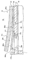
- FIG. 1 is a longitudinal sectional view of a compressor according to Embodiment 1 of the present invention.
- the principal part expanded sectional view which shows the state which the discharge reed valve opened the discharge port in the compressor of FIG.
- the top view which extracts and shows the valve plate and the discharge valve plate in which the some discharge reed valve was formed in the compressor of FIG.
- the principal part enlarged plan view which shows the state which the discharge reed valve closed the discharge port in the compressor of FIG.
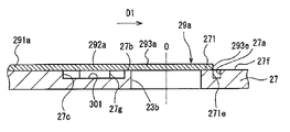
- the principal part expanded sectional view which shows the state which the discharge reed valve closed the discharge port in the compressor of FIG.
- the principal part expanded sectional view which shows the state which the discharge reed valve closed the discharge port in the compressor of FIG.
- the principal part expanded sectional view which shows the state which the discharge reed valve closed the discharge port in the compressor of FIG.
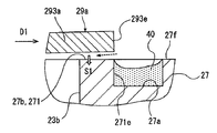
- the principal part expanded sectional view which shows the state which the discharge reed valve began to open the discharge port in the compressor of FIG.
- the principal part enlarged plan view which shows the state which the discharge reed valve closed the discharge port in the compressor which concerns on Example 2 of this invention.
- the main part expanded sectional view which shows the state which the discharge reed valve closed the discharge port in the compressor of FIG.
- the principal part enlarged plan view which shows the state which the discharge reed valve closed the discharge port in the compressor which concerns on Example 3 of this invention.
- the principal part enlarged plan view which shows the state which the discharge reed valve closed the discharge port in the compressor which concerns on Example 4 of this invention.
- the principal part enlarged plan view which shows the state which the discharge reed valve closed the discharge port.
- the principal part enlarged plan view which shows the state which the discharge reed valve closed the discharge port.
- FIG. 18 is an enlarged cross-sectional view of a main part showing a state in which the discharge reed valve closes the discharge port in the compressor of FIG. 17.
- the principal part enlarged plan view which shows the valve seat surface containing a 1st surface, a 2nd surface, and an inclined surface.
- FIG. 20 is an essential part enlarged cross-sectional view taken along line 20-20 in FIG. 19; The principal part expanded sectional view along the 21-21 line of FIG.
- FIG. 23 is an enlarged cross-sectional view of a main part taken along the line 23-23 in FIG. 22;
- FIG. 24 is an enlarged cross-sectional view of a main part along line 24-24 in FIG. 22; Sectional drawing for demonstrating the contact
- the graph which shows the relationship between the time of a compressor, and a bore
- (A) is a plan view of the main part of the compressor
- (B) and (C) are enlarged sectional views of the main part of the compressor
- (D) and (E) are The graph which shows an oil film pressure.
- the principal part expanded sectional view which shows the state which concerns on the conventional compressor and the discharge reed valve closed the discharge port.
- Embodiments 1 to 9 embodying the present invention will be described below with reference to the drawings.
- the compressor of the first embodiment is a variable capacity swash plate compressor.
- the compressor includes a cylinder block 1 having a plurality of cylinder bores 1a.
- the plurality of cylinder bores 1a are concentrically arranged at equal angular intervals and extend in parallel to each other.
- the cylinder block 1 is sandwiched between a front housing 3 positioned at the front and a rear housing 5 positioned at the rear, and is fastened by a plurality of bolts 7 in this state.
- a crank chamber 9 is formed inside the cylinder block 1 and the front housing 3.
- the rear housing 5 is formed with a suction chamber 5a and a discharge chamber 5b.
- a shaft hole 3 a is formed in the front housing 3, and a shaft hole 1 b is formed in the cylinder block 1.
- a drive shaft 11 is rotatably supported in the shaft holes 3a and 1b via a shaft seal device 9a and radial bearings 9b and 9c.
- a pulley (not shown) or an electromagnetic clutch (not shown) is provided on the drive shaft 11, and a belt (not shown) driven by a vehicle engine is wound around the pulley or the electromagnetic clutch.
- a lug plate 13 into which the drive shaft 11 is press-fitted is disposed, and a thrust bearing 15 is provided between the lug plate 13 and the front housing 3.
- the drive shaft 11 is inserted into a swash plate 17 disposed in the crank chamber 9 and supports the swash plate 17.
- the lug plate 13 and the swash plate 17 are connected by a link mechanism 19 that supports the swash plate 17 so that the tilt angle can be changed.
- valve unit 23 is provided between the cylinder block 1 and the rear housing 5. As shown in FIG. 2 in an enlarged manner, the valve unit 23 includes a suction valve plate 25 that contacts the rear end surface of the cylinder block 1, a valve plate 27 that contacts the suction valve plate 25, and a valve plate 27.
- the discharge valve plate 29 is in contact with the discharge valve plate 29, and the retainer plate 31 is in contact with the discharge valve plate 29.
- the retainer plate 31 also serves as a gasket.
- the intake valve plate 25, the valve plate 27, the discharge valve plate 29, and the retainer plate 31 are stacked in this order to constitute the valve unit 23.
- shoes 33a and 33b that are paired in the front and rear are provided between the swash plate 17 and each piston 21, and the swash plate 17 swings with each pair of shoes 33a and 33b. It is converted into a reciprocating motion of each piston 21.
- the crank chamber 9 and the suction chamber 5a are connected by an extraction passage 35a, and the crank chamber 9 and the discharge chamber 5b are connected by an air supply passage (not shown).
- a capacity control valve (not shown) is provided in the air supply passage. This capacity control valve is configured so that the opening degree of the air supply passage can be changed according to the suction pressure.
- a condenser is connected to the discharge chamber 5b by piping, the condenser is connected to the evaporator via an expansion valve by piping, and the evaporator is connected to the suction chamber 5a of the compressor by piping.
- Each compression chamber 24 is formed by the cylinder bore 1 a, the piston 21 and the valve unit 23.
- the valve plate 27, the discharge valve plate 29, and the retainer plate 31 are formed with a plurality of suction ports 23 a that allow the suction chamber 5 a to communicate with the compression chambers 24.
- the intake valve plate 25 is formed with a plurality of intake reed valves 25a for opening and closing each intake port 23a.
- the suction valve plate 25 and the valve plate 27 are formed with a plurality of discharge ports 23b for communicating the compression chambers 24 with the discharge chambers 5b.
- the discharge valve plate 29 is formed with a plurality of discharge reed valves 29a for opening and closing each discharge port 23b.
- the retainer plate 31 is formed with a retainer 31a that regulates the lift length of each discharge reed valve 29a.
- the discharge valve plate 29 includes a circular portion and a plurality of extending portions extending radially outward from the circular portion, and each extending portion discharges.
- a discharge reed valve 29a for opening and closing the port 23b is formed.
- the discharge port 23b is circular in plan view, and a fixed surface 27f, which is the surface of the valve plate 27 facing the discharge chamber 5b, has a circle surrounding the entire circumference of the discharge port 23b.
- An annular groove 27a which is an annular first groove portion, is recessed. The outer peripheral edge of the annular groove 27a is concentric with the discharge port 23b.
- an annular region sandwiched between the discharge port 23b and the annular groove 27a becomes a valve seat surface (also referred to as an eyeglass portion) 27b flush with the portion of the fixed surface 27f outside the annular groove 27a. ing.
- the suction valve plate 25 and the valve plate 27 are partition walls.
- the discharge reed valve 29a includes a fixed portion 291a fixed to the fixed surface 27f of the valve plate 27, six intermediate portions 292a extending from the fixed portion 291a along each longitudinal direction D1 and capable of being lifted, and each intermediate portion 292a. And six valve portions 293a that open and close each discharge port 23b extending along each longitudinal direction D1.
- each longitudinal direction D1 extends parallel to the fixed surface 27f and outward in the radial direction of the drive shaft 11. That is, the longitudinal direction D1 is a direction from the proximal end to the distal end of each discharge reed valve 29a.
- the intermediate part 292a and the valve part 293a when the intermediate part 292a and the valve part 293a are viewed in plan, the intermediate part 292a has a rectangular shape whose long side extends to the distal end side in the longitudinal direction D1.
- An outer edge 293e of the valve portion 293a facing the distal end in the longitudinal direction D1 has a short side of the intermediate portion 292a as a diameter, and is a semicircular arc concentric with the discharge port 23b and the annular groove 27a.
- the range of the outer edge 293e is a range indicated by a double arrow line P1.
- the angle formed by the line drawn from the center O of the discharge port 23b toward one end of the outer edge 293e and the line drawn from the center O toward the other end of the outer edge 293e is 180 °.
- the diameter of the valve portion 293a in the direction orthogonal to the longitudinal direction D1 is larger than the diameter of the valve seat surface 27b in the longitudinal direction D1.
- the receiving portion 271 bulges from the other portion of the valve seat surface 27b toward the distal end in the longitudinal direction D1, in other words, bulges radially outward of the discharge port 23b from the other portion of the valve seat surface 27b.
- the receiving portion 271 has a size that is larger than the portion other than the receiving portion 271 with respect to the dimension along the radial direction of the discharge port 23b.
- the receiving part 271 has an area larger than the part other than the receiving part 271 in the valve seat surface 27b with respect to the area per unit length along the circumferential direction of the discharge port 23b.
- the edge portion that coincides with the radially outer edge portion of the receiving portion 271 is defined as an inner edge 271e.
- the range of the inner edge 271e is a range indicated by a double arrow line P2.
- the angle is preferably within 80 °.
- the valve portion 293a In a state where the valve portion 293a closes the discharge port 23b, the central portion of the outer edge 293e coincides with the inner edge 271e, and the central portion of the outer edge 293e does not protrude to the annular groove 27a side. That is, when the valve portion 293a in a state where the discharge port 23b is closed is viewed in plan, the valve portion 293a has a tip portion that does not block the annular groove 27a in the longitudinal direction.
- the fixing surface 27f is provided with a second groove 27c that is located on the proximal end side in the longitudinal direction D1 with respect to the discharge port 23b and extends across the intermediate portion 292a in the width direction.
- a second groove 27c that is located on the proximal end side in the longitudinal direction D1 with respect to the discharge port 23b and extends across the intermediate portion 292a in the width direction.
- the shape of the second groove portion 27c is an elongated oval shape orthogonal to the longitudinal direction D1.
- the second groove portion 27c is formed deeper than the annular groove 27a.
- the lug plate 13 and the swash plate 17 rotate synchronously with the drive shaft 11, and each stroke is performed according to the inclination angle of the swash plate 17.
- the piston 21 reciprocates in each cylinder bore 1a. For this reason, the refrigerant gas in the suction chamber 5a is sucked into each compression chamber 24, compressed, and discharged into the discharge chamber 5b.
- the refrigerant gas that is compressed by the compressor contains mist-like lubricating oil.
- This lubricating oil is interposed in sliding portions such as the pistons 21, the shoes 33a and 33b, the swash plate 17, and the like to suppress wear.
- the lubricating oil also collects in the annular groove 27a and the second groove portion 27c.
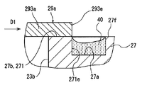
- the central portion (tip end portion) of the outer edge 293e of the valve portion 293a does not protrude to the annular groove 27a side. Therefore, as shown in an enlarged view in FIG. 6, when the discharge reed valve 29a closes the discharge port 23b, the outer edge 293e of the valve portion 293a is unlikely to come into contact with the lubricating oil 40 accumulated in the annular groove 27a.
- the valve portion 293a collides with the valve seat surface 27b.
- the collision with the valve seat surface 27b starts from a portion near the intermediate portion 292a, and stress waves are propagated along the left and right edges toward the distal end side.
- the receiving portion 271 bulges from the portion other than the receiving portion 271 on the valve seat surface 27b to the distal end side in the longitudinal direction D1 so that the central portion of the outer edge 293e does not protrude to the annular groove 27a side. Yes.
- the squeeze effect by the lubricating oil on the receiving part 271 increases when the valve part 293a and the receiving part 271 collide, and the stress wave is easily attenuated. Therefore, the collision force is alleviated and only a small stress acts on the valve portion 293a, and a large stress is hardly generated at the tip of the valve portion 293a.
- this compressor can further reduce power loss and exhibit superior durability.
- the discharge pulsation can be reduced by suppressing the delay in opening of the discharge reed valve 29a, the quietness of the compressor can be improved. Further, in this compressor, the peak pressure in the compression chamber 24 can be reduced, so that the maximum compression load is reduced, the contact surface between the thrust bearing 15, the shoes 33a, 33b and the piston 21, the shoes 33a, 33b, and the swash plate 17. This increases the reliability of the sliding surface.
- annular groove 27a is recessed in the fixed surface 27f. Therefore, in a state where the discharge reed valve 29a closes the discharge port 23b, the intermediate portion 292a and the circular arc portion 27g (shown in FIG. 4) of the annular groove 27a overlap in a wide range. For this reason, the area where the fixing surface 27f and the intermediate portion 292a are in close contact with each other is reduced by the overlapping area. For this reason, the opening delay of the discharge reed valve 29a can be reduced.
- the second groove 27c is recessed in the fixed surface 27f. For this reason, in a state where the discharge reed valve 29a closes the discharge port 23b, foreign matter is prevented from being caught in the intermediate portion 292a.
- the intermediate part 292a and the valve part 293a when the intermediate part 292a and the valve part 293a are viewed in plan, the intermediate part 292a has a rectangular shape whose long side extends to the tip side in the longitudinal direction D1.
- the outer edge 293e of the valve portion 293a has a short side of the intermediate portion 292a as a diameter and is a semicircular arc concentric with the annular groove 27a. Since the discharge reed valve 29a has such a simple shape, this compressor can reduce the manufacturing cost.
- a plurality of circular discharge ports 23 b are formed in the suction valve plate 25 and the valve plate 27, and a plurality of discharge reed valves 29 a are provided on the starfish-shaped discharge valve plate 29.
- the diameter of the valve portion 293a is larger than the diameter of the valve seat surface 27b in the direction orthogonal to the longitudinal direction D1.
- a receiving portion 271 that is a tip portion is formed larger in the radial direction than the other portions. For this reason, in this compressor, the valve portion 293a can reliably contact the valve seat surface 27b to close the discharge port 23b.
- Example 2 In the compressor of the second embodiment, a communication groove 301 is added to the compressor of the first embodiment as shown in FIGS. Other configurations are the same as those of the compressor of the first embodiment. For this reason, the same code
- the communication groove 301 is formed in the fixed surface 27f, and communicates the annular groove 27a and the second groove portion 27c. As shown in FIG. 8, when the discharge reed valve 29a with the discharge port 23b closed is viewed in plan, the communication groove 301 has a narrower width than the intermediate portion 292a, and the center in the width direction of the intermediate portion 292a is long. It extends along the direction D1.
- the annular groove 27a, the second groove portion 27c, and the communication groove 301 have the same depth.
- the portions other than the communication groove 301 on the fixed surface 27f are contact portions 302a and 302b that contact the discharge reed valve 29a.
- the abutting portions 302a and 302b are positioned on both sides in the width direction of the communication groove 301 on the fixed surface 27f, and overlap the intermediate portion 292a when the discharge reed valve 29a with the discharge port 23b closed is viewed in plan view.
- the width of the communication groove 301 is about 50% to 75% with respect to the width of the intermediate portion 292a, and the contact portions 302a and 302b can reliably support the intermediate portion 292a.
- Example 3 In the compressor of the third embodiment, as shown in FIG. 10, when the valve portion 293a with the discharge port 23b closed is viewed in plan, the outer edge 293e facing the distal end side in the longitudinal direction D1 of the valve portion 293a is a receiving portion. It is located on the base end side in the longitudinal direction D1 with respect to the inner edge 271e of the annular groove 27a coinciding with the radially outer edge of 271.
- Other configurations are the same as those of the compressor of the first embodiment.
- the compressor of the third embodiment having such a configuration has the same advantages as the compressor of the first embodiment.
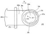
- Example 4 In the compressor according to the fourth embodiment, as shown in FIGS. 11 and 12, a portion of the valve seat surface 27b on the distal end side in the longitudinal direction D1 is a receiving portion 271 and is located on the root side in the longitudinal direction D1.
- the portion is a receiving portion 272.
- the two receiving portions 271 and 272 bulge toward the distal end side and the proximal end side in the longitudinal direction D1 from other portions of the valve seat surface 27b.
- the receiving portions 271 and 272 have an area per unit length along the circumferential direction of the discharge port 23b that is larger than other portions of the valve seat surface 27b.
- Other configurations are the same as those of the compressor of the first embodiment.
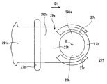
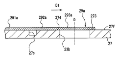
- a first groove portion 27p having a C-shape in a plan view surrounding the proximal end portion and the left and right portions of the discharge port 23b is recessed in the fixed surface 27f.
- the portion on the distal end side in the longitudinal direction D1 is a receiving portion 273. That is, the receiving part 273 bulges from the other part of the valve seat surface 27b toward the distal end side in the longitudinal direction D1, and is continuous with the fixed surface 27f.
- Other configurations are the same as those of the compressor of the first embodiment.
- the receiving portion 273 can be formed larger by widening the gap between the opposing ends of the first groove portion 27p having a C-shape in plan view.
- the valve portion 293a of the discharge reed valve 29a collides with the receiving portion 273, the lubricating oil on the large receiving portion 273 can reliably relieve the collision force. Therefore, only a small stress acts on the valve portion 293a, and a large stress is hardly generated at the tip of the valve portion 293a.
- the discharge reed valve 29a can be effectively prevented from being damaged, and excellent durability can be surely exhibited.
- Other advantages are the same as those of the first embodiment.
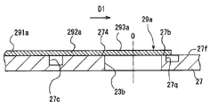
- a first groove portion 27q having a reverse C-shape in a plan view is provided in the fixed surface 27f so as to surround the front end portion and the left and right portions of the discharge port 23b.
- a portion on the base end side in the longitudinal direction D1 is a receiving portion 274. That is, the receiving portion 274 bulges from the other portion of the valve seat surface 27b to the proximal end side in the longitudinal direction D1, and continues to the fixed surface 27f.
- Other configurations are the same as those of the compressor of the first embodiment.
- Example 7 In the compressor of the seventh embodiment, as shown in FIGS. 17 and 18, arc-shaped first groove portions 27r that surround the right and left of the discharge port 23b are recessed in the fixed surface 27f. For this reason, in the fixed surface 27f, a portion on the distal end side in the longitudinal direction D1 is a receiving portion 273, and a portion on the proximal end side is a receiving portion 274. Other configurations are the same as those of the compressor of the first embodiment.
- valve seat surface 27b As shown in FIGS. 13 and 14, in the compressor of the fifth embodiment, the entire valve seat surface 27b is flush with the fixed surface 27f outside the first groove portion 27p.
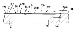
- the valve seat surface 827b includes a first surface 801, a second surface 802, and a pair of inclined surfaces 803L and 803R.
- Other configurations such as the first groove portion 27p, the second groove portion 27c, and the receiving portion 273 are the same as those of the compressor of the fifth embodiment.
- the first surface 801 when the valve seat surface 827b is viewed in plan, the first surface 801 includes a receiving portion 273 that is a portion on the distal end side in the longitudinal direction D1 on the fixed surface 27f and a portion on the distal end side of the discharge port 23b. And a pair of arc portions 801L and 801R extending from the receiving portion 273 so as to surround. As shown in FIGS. 20 and 21, the receiving portion 273 and the arc portions 801L and 801R are flush with each other.
- the second surface 802 surrounds the discharge port 23b in an arc shape between the discharge port 23b and a portion on the proximal end side in the longitudinal direction D1 in the first groove 27p. Both ends of the second surface 802 extend toward both arc portions 801L and 801R, respectively. As shown in FIGS. 20 and 21, the second surface 802 is set lower than the first surface 801. The height difference between the first surface 801 and the second surface 802 is set small enough to allow the valve portion 293a to contact the entire valve seat surface 827b without excessive deformation. In the present embodiment, the second surface 802 is about 20 ⁇ m lower than the first surface 801.
- both inclined surfaces 803L and 803R are located between both arc portions 801L and 801R of the first surface 801 and the second surface 802, respectively.
- the base end side portions in the longitudinal direction D1 of both the inclined surfaces 803L and 803R are connected to the second surface 802, respectively, and the distal end sides in the longitudinal direction D1 of the both inclined surfaces 803L and 803R are connected to both arc portions 801L and 801R, respectively.
- both inclined surfaces 803L and 803R are gently inclined from the second surface 802 to both arc portions 801L and 801R, and the height is gradually displaced.
- a center line C1 along the longitudinal direction D1 is hypothesized, and the upper side of the center line C1 in FIG. 19 is the left side, and the lower side of the center line C1 is the right side.
- a distance along the longitudinal direction D1 between the center O of the discharge port 23b and the base end side end of the left inclined surface 803L is L1.
- the distance along the longitudinal direction D1 between the center O and the end portion on the tip side of the left inclined surface 803L is L2.
- a distance along the longitudinal direction D1 between the center O and the end portion on the base end side of the right inclined surface 803R is defined as R1.
- the distance along the longitudinal direction D1 between the center O and the end portion on the distal end side of the right inclined surface 803R is R2.
- the distance L1 is shorter than the distance R1
- the distance L2 is also shorter than the distance R2. That is, the valve seat surface 827b is asymmetric on the left and right of the center line C1.
- the second surface 802 is lower than the first surface 801.
- the valve portion 293a is instantaneously closed when the discharge reed valve 29a closes the discharge port 23b.
- the timing at which the collision between the second surface 802 and the second surface 802 can be delayed. For this reason, the timing at which the stress wave due to the collision between the valve portion 293a and the second surface 802 propagates to the receiving portion 273 formed on the first surface 801 can also be delayed.
- the proximal end portion of the valve portion 293a bends along the second surface 802 and the inclined surfaces 803L and 803R, and the discharge port 23b is gradually closed from the proximal end side, whereby the distal end of the valve portion 293a is the receiving portion.
- the impact at the time of colliding with 273 can be reduced.
- both the inclined surfaces 803L and 803R are gradually displaced in height from the second surface 802 to the first surface 801, stress waves due to the collision between the valve portion 293a and the second surface 802 are both generated. It is difficult to be amplified when passing through the inclined surfaces 803L and 803R. Therefore, in this compressor, a large stress is hardly generated at the tip of the valve portion 293a.
- the valve seat surface 827b is asymmetric on the left and right of the center line C1.
- Example 9 As shown in FIGS. 4 and 5, in the compressor of the first embodiment, the entire valve seat surface 27 b is flush with the fixed surface 27 f outside the first groove portion 27 a.
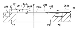
- the valve seat surface 927b includes a first surface 901, a second surface 902, and a pair of inclined surfaces 903L and 903R.
- Other configurations of the first groove portion 27a, the second groove portion 27c, the receiving portion 271 and the like are the same as those of the compressor of the first embodiment.
- the first surface 901 is located between the discharge port 23b and the portion on the distal end side in the longitudinal direction D1 in the first groove portion 27a.
- the first surface 901 includes a receiving portion 271 that bulges toward the distal end side in the longitudinal direction D1, and a pair of arc portions 901L and 901R extending from the receiving portion 271 so as to surround a portion on the distal end side of the discharge port 23b.
- the receiving portion 271 and the arc portions 901L and 901R are flush with each other.
- the second surface 902 has the same configuration as the second surface 802 of the eighth embodiment, the description is simplified. As shown in FIG. 22, the second surface 902 surrounds the discharge port 23b in an arc shape between the discharge port 23b and a portion on the proximal end side in the longitudinal direction D1 in the first groove portion 27a. The second surface 902 is lower than the first surface 901 as shown in FIGS.
- Both the inclined surfaces 903L and 903R have the same configuration as the both inclined surfaces 803L and 803R of the eighth embodiment, so that the description is simplified. As shown in FIGS. 22 to 24, both inclined surfaces 903L and 903R are located between both arc portions 901L and 901R of the first surface 901 and the second surface 902, respectively, and both arc portions 901L from the second surface 902. , The height is gradually displaced to 901R.
- the distance along the longitudinal direction D1 between the center O of the discharge port 23b and the proximal end of the left inclined surface 903L is L3. Further, a distance along the longitudinal direction D1 between the center O and the end portion on the tip side of the left inclined surface 903L is defined as L4. Furthermore, a distance along the longitudinal direction D1 between the center O and the end portion on the base end side of the right inclined surface 903R is defined as R3. Further, the distance along the longitudinal direction D1 between the center O and the end portion on the tip side of the right inclined surface 903R is defined as R4. Then, the distance L3 is shorter than the distance R3, and the distance L4 is also shorter than the distance R4. That is, the valve seat surface 927b is also asymmetrical on the left and right of the center line C1, similarly to the valve seat surface 827b of the eighth embodiment.
- the compressor of the ninth embodiment having such a configuration has the same advantages as the compressor of the eighth embodiment.
- the second groove portion 27c is formed deeper than the annular groove 27a, and in the second embodiment, the annular groove 27a, the second groove portion 27c, and the communication groove 301 are formed at the same depth. It is not limited to them.
- a communication groove similar to the communication groove 301 in the second embodiment is provided between the first groove portions 27p, 27a and the second groove portion 27c in the compressors of the eighth and ninth embodiments, so that the first groove portions 27p, 27a are provided. And the second groove 27c may be communicated with each other.
- the distance L1 and the distance R1 are made equal, and the distance L2 and the distance R2 are made equal, so that the valve seat surface 827b is symmetrical on the left and right of the center line C1.
- the ninth embodiment a configuration in which the distance L3 and the distance R3 are equal and the distance L4 and the distance R4 are equal is also included in the present invention.
- the present invention can be suitably used for a vehicle air conditioner.
Landscapes
- Engineering & Computer Science (AREA)
- General Engineering & Computer Science (AREA)
- Mechanical Engineering (AREA)
- Compressor (AREA)
Abstract
Description
実施例1の圧縮機は容量可変型斜板式圧縮機である。この圧縮機は、図1に示すように、複数個のシリンダボア1aを有するシリンダブロック1を備える。複数個のシリンダボア1aは同心円状に互いに等角度間隔で位置するとともに互いに平行に延びる。シリンダブロック1は、前方に位置するフロントハウジング3と後方に位置するリヤハウジング5とに挟持され、この状態で複数本のボルト7によって締結されている。シリンダブロック1とフロントハウジング3とによって内部にクランク室9が形成されている。リヤハウジング5には吸入室5aと吐出室5bとが形成されている。
実施例2の圧縮機においては、図8及び図9に示すように、実施例1の圧縮機に連通溝301が追加されている。その他の構成は、実施例1の圧縮機と同一である。このため、同一の構成については同一の符号を付して、説明を省略又は簡略する。
実施例3の圧縮機において、図10に示すように、吐出ポート23bを閉じた状態の弁部293aを平面視した場合、弁部293aにおける長手方向D1の先端側を向く外縁293eは、受け部271の径方向外側の縁部に一致する環状溝27aの内縁271eに対して、長手方向D1において基端側に位置している。その他の構成は、実施例1の圧縮機と同一である。
実施例4の圧縮機において、図11及び図12に示すように、弁座面27bのうち、長手方向D1の先端側の部分が受け部271とされているとともに、長手方向D1の根元側の部分が受け部272とされている。2つの受け部271、272は、弁座面27bにおける他の部分より長手方向D1の先端側及び基端側に膨出している。これにより、受け部271、272は、吐出ポート23bの周方向に沿った単位長さあたりの面積について、弁座面27bにおける他の部分より大きい面積を有している。その他の構成は、実施例1の圧縮機と同一である。
実施例5の圧縮機において、図13及び図14に示すように、固定面27fに吐出ポート23bの基端側の部分及び左右の部分を囲う平面視C字形状の第1溝部27pが凹設されている。このため、固定面27fにおいて、長手方向D1の先端側の部分が受け部273とされている。すなわち、受け部273は、弁座面27bにおける他の部分より長手方向D1の先端側に膨出して、固定面27fに連続している。その他の構成は、実施例1の圧縮機と同一である。
実施例6の圧縮機において、図15及び図16に示すように、固定面27fに吐出ポート23bの先端側の部分及び左右の部分を囲う平面視逆C字形状の第1溝部27qが凹設されている。このため、固定面27fにおいて、長手方向D1の基端側の部分が受け部274とされている。すなわち、受け部274は、弁座面27bにおける他の部分より長手方向D1の基端側に膨出して、固定面27fに連続している。その他の構成は、実施例1の圧縮機と同一である。
実施例7の圧縮機において、図17及び図18に示すように、固定面27fに吐出ポート23bの左右を囲う円弧形状の第1溝部27rが凹設されている。このため、固定面27fにおいて、長手方向D1の先端側の部分が受け部273とされているとともに、基端側の部分が受け部274とされている。その他の構成は、実施例1の圧縮機と同一である。
図13及び図14に示すように、実施例5の圧縮機では、弁座面27b全体が第1溝部27pより外側の固定面27fと面一とされている。これに対して、実施例8の圧縮機では、図19~図21に示すように、弁座面827bが第1面801、第2面802及び一対の傾斜面803L、803Rを備える。第1溝部27p、第2溝部27c及び受け部273等のその他の構成は、実施例5の圧縮機と同一である。
図4及び図5に示すように、実施例1の圧縮機では、弁座面27b全体が第1溝部27aより外側の固定面27fと面一とされている。これに対して、実施例9の圧縮機では、図22~図24に示すように、弁座面927bが第1面901、第2面902及び一対の傾斜面903L、903Rを備える。第1溝部27a、第2溝部27c及び受け部271等のその他の構成は、実施例1の圧縮機と同一である。
Claims (7)
- 吐出室と、
圧縮室と、
吐出室と圧縮室との間に設けられるとともに、吐出室に対峙する固定面を有する隔壁であって、該隔壁は吐出室と圧縮室とを連通可能な吐出ポートを有する、前記隔壁と、
長手方向に沿って延びる長さと、先端と、基端と、を有する吐出リード弁であって、該吐出リード弁は、前記基端に位置して前記固定面に固定された固定部と、該固定部から前記長手方向に沿って前記先端に向かって延びるとともに前記固定面に対してリフト可能な中間部と、該中間部から前記長手方向に沿って前記先端に向かってさらに延びるとともに前記吐出ポートを開閉可能な弁部と、を含む、前記吐出リード弁と、
を備え、
前記固定面は、前記吐出ポートを取り巻くように延びる第1溝部と、前記吐出ポート及び前記第1溝部の間に位置する弁座面とを有し、前記弁部は前記吐出ポートを閉じるべく前記弁座面に当接可能であり、前記吐出ポートを閉じた状態の前記吐出リード弁を平面視した場合、前記第1溝部は前記中間部と重なる範囲まで延在しており、
前記吐出ポートを閉じた状態の前記弁部を平面視した場合、前記弁部の前記長手方向における先端側の部位は前記第1溝部を塞がないように形成されており、
前記弁座面は、前記長手方向において前記先端側及び基端側の少なくとも一方に位置する受け部を有し、該受け部は前記弁座面における他の部分より前記長手方向において前記先端側及び前記基端側の少なくとも一方に膨出する、圧縮機。 - 前記弁座面は、前記長手方向において前記吐出リード弁の先端側に位置するとともに前記第1溝部より外側の前記固定面の部位と面一をなす第1面と、前記長手方向において前記吐出リード弁の基端側に位置するとともに第1面より低い高さを有する第2面と、第1面と第2面との間に位置し、第2面から第1面まで徐々に変位する高さを有する傾斜面と、を含み、
前記受け部は、第1面に形成されている請求項1に記載の圧縮機。 - 前記弁座面は、前記長手方向に沿った中心線を仮想した場合、該中心線の左右で非対称である請求項2に記載の圧縮機。
- 前記第1溝部は、前記吐出ポートを周方向に囲む環状溝である請求項1乃至3のいずれか1項に記載の圧縮機。
- 前記第1溝部は、前記長手方向における先端側の部分を除いて前記吐出ポートを周方向に囲むC字形状をなす請求項1乃至3のいずれか1項に記載の圧縮機。
- 前記固定面は、前記吐出ポートに対して前記長手方向の基端側に位置する第2溝を有し、該第2溝は、前記吐出ポートを閉じた状態の前記吐出リード弁を平面視した場合、前記中間部をその幅方向に跨いで延びる請求項1乃至5のいずれか1項に記載の圧縮機。
- 前記固定面は、前記吐出ポートを閉じた状態の前記吐出リード弁を平面視した場合、前記中間部と重なる範囲に位置するとともに前記長手方向に沿って延びて前記第1溝部と前記第2溝部とを連通させる連通溝を有する請求項6に記載の圧縮機。
Priority Applications (3)
| Application Number | Priority Date | Filing Date | Title |
|---|---|---|---|
| US13/637,558 US8869837B2 (en) | 2010-03-31 | 2011-03-23 | Compressor |
| DE112011101172.5T DE112011101172B4 (de) | 2010-03-31 | 2011-03-23 | Verdichter |
| CN201180015916.9A CN102822525B (zh) | 2010-03-31 | 2011-03-23 | 压缩机 |
Applications Claiming Priority (4)
| Application Number | Priority Date | Filing Date | Title |
|---|---|---|---|
| JP2010083803 | 2010-03-31 | ||
| JP2010-083803 | 2010-03-31 | ||
| JP2011029432A JP5559720B2 (ja) | 2010-03-31 | 2011-02-15 | 圧縮機 |
| JP2011-029432 | 2011-02-15 |
Publications (1)
| Publication Number | Publication Date |
|---|---|
| WO2011125501A1 true WO2011125501A1 (ja) | 2011-10-13 |
Family
ID=44762455
Family Applications (1)
| Application Number | Title | Priority Date | Filing Date |
|---|---|---|---|
| PCT/JP2011/057024 Ceased WO2011125501A1 (ja) | 2010-03-31 | 2011-03-23 | 圧縮機 |
Country Status (5)
| Country | Link |
|---|---|
| US (1) | US8869837B2 (ja) |
| JP (1) | JP5559720B2 (ja) |
| CN (1) | CN102822525B (ja) |
| DE (1) | DE112011101172B4 (ja) |
| WO (1) | WO2011125501A1 (ja) |
Cited By (1)
| Publication number | Priority date | Publication date | Assignee | Title |
|---|---|---|---|---|
| EP2594793A3 (en) * | 2011-11-17 | 2016-07-20 | Kabushiki Kaisha Toyota Jidoshokki | Compressor |
Families Citing this family (10)
| Publication number | Priority date | Publication date | Assignee | Title |
|---|---|---|---|---|
| JP5652613B2 (ja) | 2011-03-08 | 2015-01-14 | サンデン株式会社 | 圧縮機の弁装置 |
| JP5478577B2 (ja) | 2011-09-27 | 2014-04-23 | 株式会社豊田自動織機 | 圧縮機 |
| JP5478579B2 (ja) | 2011-09-29 | 2014-04-23 | 株式会社豊田自動織機 | 圧縮機 |
| CN106484985B (zh) * | 2016-09-29 | 2019-10-01 | Tcl空调器(中山)有限公司 | 基于计算机辅助工程仿真技术的管路设计方法 |
| WO2018062479A1 (ja) * | 2016-09-30 | 2018-04-05 | 株式会社ヴァレオジャパン | 圧縮機の弁構造 |
| JPWO2018110449A1 (ja) * | 2016-12-12 | 2019-10-24 | 株式会社ヴァレオジャパン | 圧縮機の弁構造 |
| JP7201311B2 (ja) | 2017-07-19 | 2023-01-10 | 株式会社日立産機システム | 圧縮機 |
| JP2023165449A (ja) * | 2022-05-06 | 2023-11-16 | 三菱重工サーマルシステムズ株式会社 | 圧縮機 |
| CN115638436A (zh) * | 2022-10-26 | 2023-01-24 | 芜湖美的智能厨电制造有限公司 | 机头组件和集成式厨房电器 |
| JP2026059756A (ja) * | 2024-09-26 | 2026-04-07 | ダイキン工業株式会社 | ロータリ圧縮機および冷凍サイクル装置 |
Citations (3)
| Publication number | Priority date | Publication date | Assignee | Title |
|---|---|---|---|---|
| JP2005105975A (ja) * | 2003-09-30 | 2005-04-21 | Calsonic Kansei Corp | 圧縮機の弁構造 |
| WO2009054209A1 (ja) * | 2007-10-26 | 2009-04-30 | Sanden Corporation | 弁板装置 |
| WO2009119316A1 (ja) * | 2008-03-28 | 2009-10-01 | サンデン株式会社 | 往復動圧縮機 |
Family Cites Families (16)
| Publication number | Priority date | Publication date | Assignee | Title |
|---|---|---|---|---|
| US4781540A (en) * | 1985-12-05 | 1988-11-01 | Kabushiki Kaisha Toyoda Jidoshokki Seisakusho | Piston type compressor for air conditioning unit having asymmetric valve mechanism |
| KR960002111Y1 (ko) * | 1991-05-06 | 1996-03-14 | 삼성전자 주식회사 | 압축기의 토출 밸브 장치 |
| JPH0861241A (ja) * | 1994-08-15 | 1996-03-08 | Sanden Corp | 弁板装置 |
| CN1071002C (zh) * | 1994-11-15 | 2001-09-12 | 三电有限公司 | 流体移动装置的阀门排放机构 |
| EP0774582B1 (en) * | 1995-11-14 | 2000-01-26 | Sanden Corporation | Valved discharge mechanism of a fluid displacement apparatus |
| JPH11117867A (ja) | 1997-10-14 | 1999-04-27 | Calsonic Corp | コンプレッサ |
| JP3957379B2 (ja) * | 1997-12-02 | 2007-08-15 | サンデン株式会社 | 弁板装置 |
| US5884665A (en) | 1998-05-19 | 1999-03-23 | General Motors Corporation | Air conditioning reed valve support seat |
| JP2000054961A (ja) | 1998-06-05 | 2000-02-22 | Toyota Autom Loom Works Ltd | 圧縮機の吸入弁装置 |
| JP2000257561A (ja) * | 1999-03-09 | 2000-09-19 | Sanden Corp | 弁装置 |
| JP2000345966A (ja) * | 1999-06-01 | 2000-12-12 | Sanden Corp | 圧縮機 |
| US7390176B2 (en) * | 2001-10-05 | 2008-06-24 | Carrier Corporation | Multi-port suction reed valve with optimized tips |
| KR20030032629A (ko) * | 2001-10-19 | 2003-04-26 | 삼성광주전자 주식회사 | 압축기의 고효율 밸브조립체 |
| US7014433B2 (en) * | 2003-02-13 | 2006-03-21 | Carrier Corporation | Shaped valve seats in displacement compressors |
| JP4497936B2 (ja) * | 2003-03-20 | 2010-07-07 | 本田技研工業株式会社 | リードバルブ |
| US7014419B2 (en) * | 2004-02-27 | 2006-03-21 | Honeywell International, Inc. | Passive improved air turbine starter lubrication system |
-
2011
- 2011-02-15 JP JP2011029432A patent/JP5559720B2/ja not_active Expired - Fee Related
- 2011-03-23 WO PCT/JP2011/057024 patent/WO2011125501A1/ja not_active Ceased
- 2011-03-23 DE DE112011101172.5T patent/DE112011101172B4/de not_active Expired - Fee Related
- 2011-03-23 CN CN201180015916.9A patent/CN102822525B/zh not_active Expired - Fee Related
- 2011-03-23 US US13/637,558 patent/US8869837B2/en not_active Expired - Fee Related
Patent Citations (3)
| Publication number | Priority date | Publication date | Assignee | Title |
|---|---|---|---|---|
| JP2005105975A (ja) * | 2003-09-30 | 2005-04-21 | Calsonic Kansei Corp | 圧縮機の弁構造 |
| WO2009054209A1 (ja) * | 2007-10-26 | 2009-04-30 | Sanden Corporation | 弁板装置 |
| WO2009119316A1 (ja) * | 2008-03-28 | 2009-10-01 | サンデン株式会社 | 往復動圧縮機 |
Cited By (1)
| Publication number | Priority date | Publication date | Assignee | Title |
|---|---|---|---|---|
| EP2594793A3 (en) * | 2011-11-17 | 2016-07-20 | Kabushiki Kaisha Toyota Jidoshokki | Compressor |
Also Published As
| Publication number | Publication date |
|---|---|
| JP5559720B2 (ja) | 2014-07-23 |
| CN102822525A (zh) | 2012-12-12 |
| JP2011226464A (ja) | 2011-11-10 |
| US20130014841A1 (en) | 2013-01-17 |
| DE112011101172B4 (de) | 2018-05-09 |
| CN102822525B (zh) | 2015-09-16 |
| US8869837B2 (en) | 2014-10-28 |
| DE112011101172T5 (de) | 2013-01-10 |
Similar Documents
| Publication | Publication Date | Title |
|---|---|---|
| JP5559720B2 (ja) | 圧縮機 | |
| JP5633520B2 (ja) | 圧縮機 | |
| JP5422591B2 (ja) | 圧縮機 | |
| JP2009509076A (ja) | 圧縮機 | |
| JP5478579B2 (ja) | 圧縮機 | |
| JP4722392B2 (ja) | 往復密閉コンプレッサのピストンのための装着構成 | |
| US20110290348A1 (en) | Compressor Valve Plate Device | |
| JP2010169077A (ja) | 圧縮機 | |
| KR20140024913A (ko) | 밀폐식 컴프레서용 밸브 장치 | |
| WO2018110449A1 (ja) | 圧縮機の弁構造 | |
| EP1808602B1 (en) | Muffler installation structure for compressor | |
| WO2018062479A1 (ja) | 圧縮機の弁構造 | |
| JP2009293546A (ja) | 密閉形圧縮機、およびこれを用いた冷蔵庫又はルームエアコン | |
| JP5142585B2 (ja) | 密閉形圧縮機及び冷蔵庫 | |
| JP5824607B2 (ja) | 密閉型圧縮機 | |
| JP2008208961A (ja) | 圧縮機 | |
| CN114033686B (zh) | 压缩结构、压缩机以及具有其的空调器 | |
| JP2005180365A (ja) | 圧縮機 | |
| JP2010059869A (ja) | 圧縮機 | |
| JP2010019217A (ja) | 圧縮機 | |
| JP2006291731A (ja) | ベーンロータリ圧縮機 |
Legal Events
| Date | Code | Title | Description |
|---|---|---|---|
| WWE | Wipo information: entry into national phase |
Ref document number: 201180015916.9 Country of ref document: CN |
|
| 121 | Ep: the epo has been informed by wipo that ep was designated in this application |
Ref document number: 11765402 Country of ref document: EP Kind code of ref document: A1 |
|
| WWE | Wipo information: entry into national phase |
Ref document number: 13637558 Country of ref document: US |
|
| WWE | Wipo information: entry into national phase |
Ref document number: 1120111011725 Country of ref document: DE Ref document number: 112011101172 Country of ref document: DE |
|
| 122 | Ep: pct application non-entry in european phase |
Ref document number: 11765402 Country of ref document: EP Kind code of ref document: A1 |