WO2011125225A1 - ハニカム構造体及び排ガス浄化装置 - Google Patents
ハニカム構造体及び排ガス浄化装置 Download PDFInfo
- Publication number
- WO2011125225A1 WO2011125225A1 PCT/JP2010/056477 JP2010056477W WO2011125225A1 WO 2011125225 A1 WO2011125225 A1 WO 2011125225A1 JP 2010056477 W JP2010056477 W JP 2010056477W WO 2011125225 A1 WO2011125225 A1 WO 2011125225A1
- Authority
- WO
- WIPO (PCT)
- Prior art keywords
- honeycomb structure
- structure according
- honeycomb
- conductive member
- electrode
- Prior art date
- Legal status (The legal status is an assumption and is not a legal conclusion. Google has not performed a legal analysis and makes no representation as to the accuracy of the status listed.)
- Ceased
Links
Images


Classifications
-
- F—MECHANICAL ENGINEERING; LIGHTING; HEATING; WEAPONS; BLASTING
- F01—MACHINES OR ENGINES IN GENERAL; ENGINE PLANTS IN GENERAL; STEAM ENGINES
- F01N—GAS-FLOW SILENCERS OR EXHAUST APPARATUS FOR MACHINES OR ENGINES IN GENERAL; GAS-FLOW SILENCERS OR EXHAUST APPARATUS FOR INTERNAL-COMBUSTION ENGINES
- F01N3/00—Exhaust or silencing apparatus having means for purifying, rendering innocuous, or otherwise treating exhaust
- F01N3/02—Exhaust or silencing apparatus having means for purifying, rendering innocuous, or otherwise treating exhaust for cooling, or for removing solid constituents of, exhaust
- F01N3/021—Exhaust or silencing apparatus having means for purifying, rendering innocuous, or otherwise treating exhaust for cooling, or for removing solid constituents of, exhaust by means of filters
- F01N3/033—Exhaust or silencing apparatus having means for purifying, rendering innocuous, or otherwise treating exhaust for cooling, or for removing solid constituents of, exhaust by means of filters in combination with other devices
- F01N3/035—Exhaust or silencing apparatus having means for purifying, rendering innocuous, or otherwise treating exhaust for cooling, or for removing solid constituents of, exhaust by means of filters in combination with other devices with catalytic reactors
-
- B—PERFORMING OPERATIONS; TRANSPORTING
- B03—SEPARATION OF SOLID MATERIALS USING LIQUIDS OR USING PNEUMATIC TABLES OR JIGS; MAGNETIC OR ELECTROSTATIC SEPARATION OF SOLID MATERIALS FROM SOLID MATERIALS OR FLUIDS; SEPARATION BY HIGH-VOLTAGE ELECTRIC FIELDS
- B03C—MAGNETIC OR ELECTROSTATIC SEPARATION OF SOLID MATERIALS FROM SOLID MATERIALS OR FLUIDS; SEPARATION BY HIGH-VOLTAGE ELECTRIC FIELDS
- B03C3/00—Separating dispersed particles from gases or vapour, e.g. air, by electrostatic effect
- B03C3/34—Constructional details or accessories or operation thereof
- B03C3/40—Electrode constructions
- B03C3/45—Collecting-electrodes
- B03C3/455—Collecting-electrodes specially adapted for heat exchange with the gas stream
-
- B—PERFORMING OPERATIONS; TRANSPORTING
- B03—SEPARATION OF SOLID MATERIALS USING LIQUIDS OR USING PNEUMATIC TABLES OR JIGS; MAGNETIC OR ELECTROSTATIC SEPARATION OF SOLID MATERIALS FROM SOLID MATERIALS OR FLUIDS; SEPARATION BY HIGH-VOLTAGE ELECTRIC FIELDS
- B03C—MAGNETIC OR ELECTROSTATIC SEPARATION OF SOLID MATERIALS FROM SOLID MATERIALS OR FLUIDS; SEPARATION BY HIGH-VOLTAGE ELECTRIC FIELDS
- B03C3/00—Separating dispersed particles from gases or vapour, e.g. air, by electrostatic effect
- B03C3/34—Constructional details or accessories or operation thereof
- B03C3/40—Electrode constructions
- B03C3/45—Collecting-electrodes
- B03C3/51—Catch- space electrodes, e.g. slotted-box form
-
- B—PERFORMING OPERATIONS; TRANSPORTING
- B03—SEPARATION OF SOLID MATERIALS USING LIQUIDS OR USING PNEUMATIC TABLES OR JIGS; MAGNETIC OR ELECTROSTATIC SEPARATION OF SOLID MATERIALS FROM SOLID MATERIALS OR FLUIDS; SEPARATION BY HIGH-VOLTAGE ELECTRIC FIELDS
- B03C—MAGNETIC OR ELECTROSTATIC SEPARATION OF SOLID MATERIALS FROM SOLID MATERIALS OR FLUIDS; SEPARATION BY HIGH-VOLTAGE ELECTRIC FIELDS
- B03C3/00—Separating dispersed particles from gases or vapour, e.g. air, by electrostatic effect
- B03C3/34—Constructional details or accessories or operation thereof
- B03C3/40—Electrode constructions
- B03C3/60—Use of special materials other than liquids
- B03C3/62—Use of special materials other than liquids ceramics
-
- F—MECHANICAL ENGINEERING; LIGHTING; HEATING; WEAPONS; BLASTING
- F01—MACHINES OR ENGINES IN GENERAL; ENGINE PLANTS IN GENERAL; STEAM ENGINES
- F01N—GAS-FLOW SILENCERS OR EXHAUST APPARATUS FOR MACHINES OR ENGINES IN GENERAL; GAS-FLOW SILENCERS OR EXHAUST APPARATUS FOR INTERNAL-COMBUSTION ENGINES
- F01N3/00—Exhaust or silencing apparatus having means for purifying, rendering innocuous, or otherwise treating exhaust
- F01N3/02—Exhaust or silencing apparatus having means for purifying, rendering innocuous, or otherwise treating exhaust for cooling, or for removing solid constituents of, exhaust
- F01N3/021—Exhaust or silencing apparatus having means for purifying, rendering innocuous, or otherwise treating exhaust for cooling, or for removing solid constituents of, exhaust by means of filters
- F01N3/022—Exhaust or silencing apparatus having means for purifying, rendering innocuous, or otherwise treating exhaust for cooling, or for removing solid constituents of, exhaust by means of filters characterised by specially adapted filtering structure, e.g. honeycomb, mesh or fibrous
- F01N3/0222—Exhaust or silencing apparatus having means for purifying, rendering innocuous, or otherwise treating exhaust for cooling, or for removing solid constituents of, exhaust by means of filters characterised by specially adapted filtering structure, e.g. honeycomb, mesh or fibrous the structure being monolithic, e.g. honeycombs
-
- F—MECHANICAL ENGINEERING; LIGHTING; HEATING; WEAPONS; BLASTING
- F01—MACHINES OR ENGINES IN GENERAL; ENGINE PLANTS IN GENERAL; STEAM ENGINES
- F01N—GAS-FLOW SILENCERS OR EXHAUST APPARATUS FOR MACHINES OR ENGINES IN GENERAL; GAS-FLOW SILENCERS OR EXHAUST APPARATUS FOR INTERNAL-COMBUSTION ENGINES
- F01N3/00—Exhaust or silencing apparatus having means for purifying, rendering innocuous, or otherwise treating exhaust
- F01N3/02—Exhaust or silencing apparatus having means for purifying, rendering innocuous, or otherwise treating exhaust for cooling, or for removing solid constituents of, exhaust
- F01N3/021—Exhaust or silencing apparatus having means for purifying, rendering innocuous, or otherwise treating exhaust for cooling, or for removing solid constituents of, exhaust by means of filters
- F01N3/023—Exhaust or silencing apparatus having means for purifying, rendering innocuous, or otherwise treating exhaust for cooling, or for removing solid constituents of, exhaust by means of filters using means for regenerating the filters, e.g. by burning trapped particles
- F01N3/027—Exhaust or silencing apparatus having means for purifying, rendering innocuous, or otherwise treating exhaust for cooling, or for removing solid constituents of, exhaust by means of filters using means for regenerating the filters, e.g. by burning trapped particles using electric or magnetic heating means
- F01N3/0275—Exhaust or silencing apparatus having means for purifying, rendering innocuous, or otherwise treating exhaust for cooling, or for removing solid constituents of, exhaust by means of filters using means for regenerating the filters, e.g. by burning trapped particles using electric or magnetic heating means using electric discharge means
-
- B—PERFORMING OPERATIONS; TRANSPORTING
- B01—PHYSICAL OR CHEMICAL PROCESSES OR APPARATUS IN GENERAL
- B01D—SEPARATION
- B01D53/00—Separation of gases or vapours; Recovering vapours of volatile solvents from gases; Chemical or biological purification of waste gases, e.g. engine exhaust gases, smoke, fumes, flue gases, aerosols
- B01D53/34—Chemical or biological purification of waste gases
- B01D53/92—Chemical or biological purification of waste gases of engine exhaust gases
- B01D53/94—Chemical or biological purification of waste gases of engine exhaust gases by catalytic processes
-
- B—PERFORMING OPERATIONS; TRANSPORTING
- B03—SEPARATION OF SOLID MATERIALS USING LIQUIDS OR USING PNEUMATIC TABLES OR JIGS; MAGNETIC OR ELECTROSTATIC SEPARATION OF SOLID MATERIALS FROM SOLID MATERIALS OR FLUIDS; SEPARATION BY HIGH-VOLTAGE ELECTRIC FIELDS
- B03C—MAGNETIC OR ELECTROSTATIC SEPARATION OF SOLID MATERIALS FROM SOLID MATERIALS OR FLUIDS; SEPARATION BY HIGH-VOLTAGE ELECTRIC FIELDS
- B03C2201/00—Details of magnetic or electrostatic separation
- B03C2201/30—Details of magnetic or electrostatic separation for use in or with vehicles
-
- F—MECHANICAL ENGINEERING; LIGHTING; HEATING; WEAPONS; BLASTING
- F01—MACHINES OR ENGINES IN GENERAL; ENGINE PLANTS IN GENERAL; STEAM ENGINES
- F01N—GAS-FLOW SILENCERS OR EXHAUST APPARATUS FOR MACHINES OR ENGINES IN GENERAL; GAS-FLOW SILENCERS OR EXHAUST APPARATUS FOR INTERNAL-COMBUSTION ENGINES
- F01N2330/00—Structure of catalyst support or particle filter
- F01N2330/06—Ceramic, e.g. monoliths
-
- F—MECHANICAL ENGINEERING; LIGHTING; HEATING; WEAPONS; BLASTING
- F01—MACHINES OR ENGINES IN GENERAL; ENGINE PLANTS IN GENERAL; STEAM ENGINES
- F01N—GAS-FLOW SILENCERS OR EXHAUST APPARATUS FOR MACHINES OR ENGINES IN GENERAL; GAS-FLOW SILENCERS OR EXHAUST APPARATUS FOR INTERNAL-COMBUSTION ENGINES
- F01N3/00—Exhaust or silencing apparatus having means for purifying, rendering innocuous, or otherwise treating exhaust
- F01N3/08—Exhaust or silencing apparatus having means for purifying, rendering innocuous, or otherwise treating exhaust for rendering innocuous
- F01N3/10—Exhaust or silencing apparatus having means for purifying, rendering innocuous, or otherwise treating exhaust for rendering innocuous by thermal or catalytic conversion of noxious components of exhaust
- F01N3/18—Exhaust or silencing apparatus having means for purifying, rendering innocuous, or otherwise treating exhaust for rendering innocuous by thermal or catalytic conversion of noxious components of exhaust characterised by methods of operation; Control
- F01N3/20—Exhaust or silencing apparatus having means for purifying, rendering innocuous, or otherwise treating exhaust for rendering innocuous by thermal or catalytic conversion of noxious components of exhaust characterised by methods of operation; Control specially adapted for catalytic conversion
- F01N3/2006—Periodically heating or cooling catalytic reactors, e.g. at cold starting or overheating
- F01N3/2013—Periodically heating or cooling catalytic reactors, e.g. at cold starting or overheating using electric or magnetic heating means
- F01N3/2026—Periodically heating or cooling catalytic reactors, e.g. at cold starting or overheating using electric or magnetic heating means directly electrifying the catalyst substrate, i.e. heating the electrically conductive catalyst substrate by joule effect
-
- F—MECHANICAL ENGINEERING; LIGHTING; HEATING; WEAPONS; BLASTING
- F01—MACHINES OR ENGINES IN GENERAL; ENGINE PLANTS IN GENERAL; STEAM ENGINES
- F01N—GAS-FLOW SILENCERS OR EXHAUST APPARATUS FOR MACHINES OR ENGINES IN GENERAL; GAS-FLOW SILENCERS OR EXHAUST APPARATUS FOR INTERNAL-COMBUSTION ENGINES
- F01N3/00—Exhaust or silencing apparatus having means for purifying, rendering innocuous, or otherwise treating exhaust
- F01N3/08—Exhaust or silencing apparatus having means for purifying, rendering innocuous, or otherwise treating exhaust for rendering innocuous
- F01N3/10—Exhaust or silencing apparatus having means for purifying, rendering innocuous, or otherwise treating exhaust for rendering innocuous by thermal or catalytic conversion of noxious components of exhaust
- F01N3/24—Exhaust or silencing apparatus having means for purifying, rendering innocuous, or otherwise treating exhaust for rendering innocuous by thermal or catalytic conversion of noxious components of exhaust characterised by constructional aspects of converting apparatus
- F01N3/28—Construction of catalytic reactors
- F01N3/2803—Construction of catalytic reactors characterised by structure, by material or by manufacturing of catalyst support
- F01N3/2825—Ceramics
- F01N3/2828—Ceramic multi-channel monoliths, e.g. honeycombs
Definitions
- the present invention relates to a honeycomb structure and an exhaust gas purification apparatus having the honeycomb structure.
- Automobile exhaust gas contains substances such as hydrocarbon compounds, carbon monoxide, and nitrogen oxides.
- a honeycomb structure composed of cordierite is used. Yes.
- a catalyst supporting layer made of alumina is formed on the surface of partition walls separating a plurality of through holes, and a catalyst such as platinum, rhodium, palladium, etc. is supported on the catalyst supporting layer.
- Patent Document 1 a catalyst body having an integral structure composed of a single honeycomb unit using a heating material such as a silicon carbide-based material as the base material of the honeycomb structure is contained in a catalyst container connected to an exhaust passage. And a terminal is joined to the outer peripheral portion of the catalyst body, and when the catalyst body is in a condition within a predetermined temperature environment, electricity is passed through the terminal from the power source to heat the substrate, and the catalyst body
- a catalytic exhaust gas purifying apparatus for an internal combustion engine that heats the engine is disclosed.
- Patent Document 2 discloses an exhaust gas filter in which a plurality of porous ceramic filters for purifying exhaust gas from an internal combustion engine are combined, and a pair of self-heating electrodes are provided at both ends. Yes.
- the exhaust gas filter described in FIG. 6 of Patent Document 2 is a combination of a filter having a substantially square cross section and a filter having a substantially isosceles triangular cross section. Since the heating electrode is provided, it is difficult to stably energize the plurality of filters. As a result, there is a problem that some of the filters do not generate sufficient heat and the exhaust gas purification ability is reduced.
- the present invention stably supplies electricity to a plurality of honeycomb units and suppresses heat generation due to disconnection and contact resistance even when a voltage is applied between electrodes via terminals from a high-capacity battery. It is an object of the present invention to provide a honeycomb structure that can be used and an exhaust gas purifying apparatus having the honeycomb structure.
- a plurality of through holes are arranged in the longitudinal direction, and a plurality of honeycomb units containing conductive ceramics are bonded via an adhesive layer, and the honeycomb unit has an outer peripheral surface.
- a pair of electrodes are provided with a pair of electrodes, and a pair of conductive members electrically connected to the plurality of the pair of electrodes is provided.
- the pair of electrodes are preferably formed on outer peripheral surfaces of both end portions in the longitudinal direction of the honeycomb unit.
- a plurality of the honeycomb units bonded to each other through the adhesive layer is a columnar shape or an elliptical column shape, and the shape of the conductive member is preferably an annular shape or an elliptical ring shape.
- the maximum width is desirably 3 mm or more and 30 mm or less.
- the electrode has a layer containing silicon or metal formed on at least a part of the surface thereof, and the conductive member has a convex portion formed on the surface facing the electrode, and the convex portion A layer containing metal or silicon is formed, and it is desirable to include a silicide produced by the reaction between the silicon and the metal, and the metal is preferably nickel.
- the conductive member has a convex portion or a pointed portion formed on the surface facing the electrode, and the convex portion or the pointed portion is pressure-bonded to the electrode.
- the electrode is preferably formed by thermal spraying or sputtering. *
- the partition walls separating the plurality of through holes preferably support a catalyst, and the catalyst is preferably platinum, rhodium or palladium.
- the conductive ceramic preferably includes silicon carbide. *
- the exhaust gas purification apparatus of the present invention has the honeycomb structure of the present invention.
- a honeycomb structure capable of stably energizing a plurality of honeycomb units and suppressing heat generation due to disconnection and contact resistance even when energized through a terminal from a high-capacity battery, and the honeycomb structure It is possible to provide an exhaust gas purifying apparatus having the following.
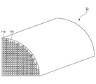
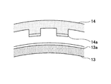
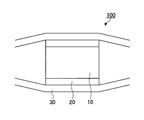
- FIG. 2 is a perspective view showing a honeycomb unit constituting the honeycomb structure of FIG. 1. It is sectional drawing which shows an example of the method of forming the electroconductive ensuring part in this invention. It is sectional drawing which shows the electroconductive ensuring part formed using the method of FIG. It is sectional drawing which shows an example of the exhaust gas purification apparatus of this invention.
- FIG. 1 shows an example of the honeycomb structure of the present invention.
- the honeycomb structure 10 four honeycomb units 11 (see FIG. 2), in which a plurality of square columnar through holes 11a are arranged in parallel in the longitudinal direction with a partition wall 11b therebetween, are bonded via an adhesive layer 12. It is cylindrical.
- the cross section perpendicular to the longitudinal direction of the honeycomb unit 11 is a fan shape having a central angle of 90 °, and the honeycomb unit 11 includes conductive ceramics.
- a pair of strip electrodes 13 are formed on the entire outer periphery of both end portions in the longitudinal direction of each honeycomb unit 11.
- the end of the honeycomb unit 11 includes the vicinity of the end of the honeycomb unit 11. Further, the vicinity of the end of the honeycomb unit 11 means that the distance from the end surface of the honeycomb unit 11 is 30 mm or less. Furthermore, the outer peripheral surface does not include the end surface.
- a pair of annular conductive members 14 that are electrically connected to the four pairs of strip electrodes 13 are provided. For this reason, since the same voltage is applied to the four honeycomb units 11 when a voltage is applied between the belt-like electrodes 13 via the annular conductive member 14 from the automobile battery, a current can be flowed stably. Further, for example, even when a voltage is applied between the band-shaped electrodes 13 via the annular conductive member 14 from a high-capacity battery mounted on a hybrid vehicle, the annular conductive member 14 and the band-shaped electrode 13 are physically adhered to each other. Therefore, heat generation due to contact resistance can be suppressed.
- the conductive ceramic is not particularly limited as long as it can generate sufficient heat when a predetermined current is passed through the honeycomb unit 11, and examples thereof include silicon carbide doped with aluminum nitride, aluminum or the like.
- the honeycomb unit 11 preferably has a resistance between the strip electrodes 13 of 1 to 1 ⁇ 10 3 ⁇ . If the resistance between the strip electrodes 13 of the honeycomb unit 11 is less than 1 ⁇ , even if the honeycomb unit 11 is energized, heat is not sufficiently generated due to Joule's law. On the other hand, if the resistance between the strip electrodes 13 of the honeycomb unit 11 exceeds 1 ⁇ 10 3 ⁇ , the voltage between the strip electrodes 13 from the high capacity battery mounted on the hybrid vehicle through the annular conductive member 14, for example. Is applied, the current flowing through the honeycomb unit 11 becomes small, and it becomes difficult to sufficiently heat the honeycomb unit 11.
- the honeycomb unit 11 preferably has a porosity of 25 to 50%.
- the porosity of the honeycomb unit 11 is less than 25%, the heat capacity of the honeycomb unit 11 is increased and it is difficult to generate heat.
- the porosity of the honeycomb unit 11 exceeds 50%, the strength of the honeycomb unit 11 becomes insufficient.
- the porosity of the honeycomb unit 11 can be measured using a mercury intrusion method.
- the honeycomb unit 11 preferably has a cross-sectional area of a cross section perpendicular to the longitudinal direction of 5 to 50 cm 2 .
- the cross-sectional area of the cross section perpendicular to the longitudinal direction is less than 5 cm 2 , the pressure loss of the honeycomb structure 10 tends to increase.
- the cross-sectional area of the cross section perpendicular to the longitudinal direction exceeds 50 cm 2 , cracks are likely to occur due to the thermal stress generated in the honeycomb unit 11.
- the honeycomb unit 11 preferably has an opening ratio of a cross section perpendicular to the longitudinal direction of 50 to 85%.
- the opening ratio of the cross section perpendicular to the longitudinal direction of the honeycomb unit 11 is less than 50%, the heat capacity of the honeycomb unit 11 increases and it becomes difficult to generate heat.
- the aperture ratio of the cross section perpendicular to the longitudinal direction of the honeycomb unit 11 exceeds 85%, the strength of the honeycomb unit 11 becomes insufficient.
- the density of the through-holes 11a having a cross section perpendicular to the longitudinal direction of the honeycomb unit 11 is preferably 15.5 to 186 holes / cm 2 , more preferably 31 to 155 holes / cm 2 , and 46.5 to 124 holes. / Cm 2 is more preferable.
- the density of the through-holes 11a having a cross section perpendicular to the longitudinal direction of the honeycomb unit 11 is less than 15.5 / cm 2 , it becomes difficult for the exhaust gas and the catalyst to come into contact when the catalyst is supported on the partition walls 11b. , The purification rate of exhaust gas is reduced.
- the density of the through holes 11a having a cross section perpendicular to the longitudinal direction of the honeycomb unit 11 exceeds 186 / cm 2 , the pressure loss of the honeycomb structure 10 increases.
- the thickness of the partition wall 11b of the honeycomb unit 11 is preferably 0.05 to 0.30 mm.
- the thickness of the partition wall 11b is less than 0.05 mm, the strength of the honeycomb unit 11 is lowered.
- the thickness of the partition wall 11b exceeds 0.30 mm, the heat capacity of the honeycomb unit 11 is increased and it is difficult to generate heat.
- a catalyst may be supported on the partition walls 11 b of the honeycomb unit 11.
- the catalyst supported on the partition wall 11b is not particularly limited as long as the exhaust gas can be purified, and examples thereof include platinum, rhodium, and palladium.
- a catalyst supporting layer made of ⁇ -alumina is formed on the surface of the partition wall 11b, and the catalyst is supported on the catalyst supporting layer.
- a method for producing the honeycomb unit 11 composed of silicon carbide doped with aluminum nitride is not particularly limited, and examples thereof include a method of firing a molded body formed using a raw material paste containing silicon carbide and aluminum nitride. It is done.
- the content of aluminum nitride in the raw material paste is preferably 0.1 to 30% by mass.
- the raw material paste may further contain an organic binder, a dispersion medium, a molding aid and the like, if necessary.
- Methylcellulose, carboxymethylcellulose, hydroxyethylcellulose, polyethyleneglycol, a phenol resin, an epoxy resin etc. are mentioned, You may use 2 or more types together.
- the content of the organic binder in the raw material paste is preferably 1 to 10% by mass with respect to silicon carbide.
- the dispersion medium contained in the raw material paste is not particularly limited, and examples thereof include water, an aqueous solvent such as methanol, and an organic solvent such as benzene, and two or more kinds may be used in combination.
- the molding aid contained in the raw material paste is not particularly limited, and examples thereof include ethylene glycol, dextrin, fatty acid, fatty acid soap, polyalcohol and the like.
- the method for preparing the raw material paste is not particularly limited, and examples thereof include a method of mixing using a mixer, an attritor or the like, a method of kneading using a kneader or the like.
- the dryer used for drying the molded body is not particularly limited, and examples thereof include a microwave dryer, a hot air dryer, a dielectric dryer, a vacuum dryer, a vacuum dryer, and a freeze dryer.
- the dried molded body is preferably degreased at 400 ° C. for 2 hours, for example.
- the degreased molded body is preferably fired at 2200 ° C. for 3 hours in an atmosphere of an inert gas such as argon.
- nitrogen may be introduced at the time of firing and silicon carbide may be doped with nitrogen.
- honeycomb unit 11 a honeycomb unit including a conductive material in pores existing in the base material (aggregate) may be used.
- the material constituting the substrate of the honeycomb unit is not particularly limited, and examples thereof include silicon carbide, aluminum titanate, cordierite, alumina, silica, zirconia, and zeolite.
- the method for producing the honeycomb unit base material composed of silicon carbide is not particularly limited, and examples of the method for producing the honeycomb unit 11 include a method using a raw material paste not containing aluminum nitride.
- the conductive material contained in the pores present in the substrate of the honeycomb unit is not particularly limited as long as it can generate sufficient heat when energized. Etc.
- the method for forming a conductive layer containing silicon as the conductive material is not particularly limited, and examples thereof include a method of impregnating the surface of the substrate of the honeycomb unit with molten silicon or a slurry containing silicon or a silicon precursor.
- the shape of the cross section perpendicular to the longitudinal direction of the honeycomb unit 11 is not limited to the fan shape as long as the strip electrode 13 electrically connected to the annular conductive member 14 can be formed.
- a through hole having a triangular prism shape, a hexagonal column shape, or the like may be provided instead of the through hole 11a.
- the adhesive layer 12 for bonding the honeycomb unit 11 preferably has a thickness of 0.5 to 2 mm.
- the thickness of the adhesive layer 12 is less than 0.5 mm, the adhesive strength becomes insufficient.
- the thickness of the adhesive layer 12 exceeds 2 mm, the pressure loss of the honeycomb structure 10 tends to increase.
- the method of adhering the honeycomb unit 11 is not particularly limited, and examples thereof include a method of drying and solidifying after applying the adhesive layer paste.
- the adhesive layer paste is not particularly limited, and examples thereof include a mixture of inorganic binder and inorganic particles, a mixture of inorganic binder and inorganic fibers, a mixture of inorganic binder, inorganic particles, and inorganic fibers.
- the inorganic fiber contained in the adhesive layer paste is not particularly limited, and examples thereof include alumina, silica, silicon carbide, silica alumina, glass, potassium titanate, and aluminum borate, and two or more kinds may be used in combination. Among these, silica alumina is preferable.
- the inorganic binder contained in the adhesive layer paste is not particularly limited, but includes inorganic sols such as alumina sol, silica sol, titania sol, water glass, clay minerals such as clay, kaolin, montmorillonite, sepiolite, and attapulgite. Two or more species may be used in combination. Of these, alumina sol, silica sol, and titania sol are preferable.
- the inorganic particles contained in the adhesive layer paste are not particularly limited, and include silicon carbide, alumina, silica, titania, zirconia, ceria, mullite, etc., and two or more kinds may be used in combination. Among these, silicon carbide is preferable.
- the adhesive layer paste may contain an organic binder.
- the organic binder contained in the adhesive layer paste is not particularly limited, and examples thereof include polyvinyl alcohol, methyl cellulose, ethyl cellulose, carboxymethyl cellulose and the like, and two or more kinds may be used in combination.
- the honeycomb unit constituting the elliptical columnar honeycomb structure preferably has an elliptical fan-shaped cross section perpendicular to the longitudinal direction.
- an ellipse and an ellipse in an elliptical sector include a track shape in which two semicircles are connected by two line segments having the same length.
- the strip electrode 13 is preferably made of metal.
- the method for forming the strip electrode 13 is not particularly limited, and examples thereof include thermal spraying and sputtering.
- a strip electrode formed on a part of the outer periphery of the honeycomb unit 11, that is, a strip electrode shorter than the outer periphery of the honeycomb unit 11, may be formed. May be formed.
- the annular conductive member 14 functions as a terminal.
- annular circular shape shall include the circular ring which is not closed.
- the maximum width of the annular conductive member 14 is preferably 3 to 30 mm.
- the maximum width of the annular conductive member 14 is less than 3 mm, for example, when a voltage is applied between the band-shaped electrodes 13 via the annular conductive member 14 from a high-capacity battery mounted on a hybrid vehicle, the annular conductive member 14 The current per unit volume flowing through the member 14 increases, and the annular conductive member 14 is easily damaged.
- the width of the annular conductive member 14 exceeds 30 mm, the volume of the honeycomb unit 11 that generates heat when a voltage is applied between the strip electrodes 13 via the annular conductive member 14 is reduced, and the honeycomb structure 10 emits exhaust gas. It cannot be purified sufficiently.
- the maximum width of the annular conductive member 14 means the maximum value of the length in the longitudinal direction of the annular conductive member 14.
- a conductive securing portion is formed between the annular conductive member 14 and the strip electrode 13.
- the material constituting the conductive securing portion is not particularly limited, and examples thereof include silicides such as nickel silicide, chromium silicide, and iron silicide, metals, and the like, and two or more of them may be used in combination. Among these, nickel silicide is preferable.
- 3 and 4 show a method of forming the conductive securing portion 15 and the formed conductive securing portion 15, respectively.
- the annular conductive member 14 convex portions are formed on the surface facing the strip electrode 13 at a predetermined cycle, and a nickel layer 14 a is formed on the upper surface of the convex portions.
- a silicon layer 13 a is formed on the surface of the strip electrode 13 formed on the outer peripheral surface of the honeycomb unit 11.
- Such an annular conductive member 14 is pressed into contact with the strip electrode 13 in an atmosphere of an inert gas at 800 to 1000 ° C., so that a nickel silicide is formed between the convex portion of the annular conductive member 14 and the strip electrode 13.
- the conductive ensuring part 15 comprised from these can be formed.
- the temperature of the atmosphere in which the annular conductive member 14 is pressed against the strip electrode 13 is less than 800 ° C., the reaction between nickel and silicon does not proceed sufficiently. On the other hand, when the temperature of the atmosphere in which the annular conductive member 14 is pressed against the strip electrode 13 exceeds 1000 ° C., the strip electrode 13 is easily melted.
- the inert gas in the atmosphere that presses the annular conductive member 14 against the strip electrode 13 is not particularly limited, and examples thereof include helium, neon, argon, and nitrogen.
- the pressure for pressing the annular conductive member 14 against the strip electrode 13 is preferably 0.3 to 3.0 MPa. If the pressure at which the annular conductive member 14 is pressed against the strip electrode 13 is less than 0.3 MPa, for example, when a voltage is applied between the strip electrode 13 via the annular conductive member 14 from an automobile battery, heat is generated due to contact resistance. It tends to occur. On the other hand, when the pressure that presses the annular conductive member 14 against the strip electrode 13 exceeds 3.0 MPa, the honeycomb unit 11 is easily damaged.
- the ratio of the area of the region where the convex portion is formed to the area of the region where the convex portion on the side facing the strip electrode 13 of the annular conductive member 14 is 1/3 to 1. If the ratio of the areas is less than 1/3, the current flowing through the conductive securing portion 17 becomes small, and heat generation due to contact resistance is likely to occur. On the other hand, if the ratio of the areas exceeds 1, the convex portion of the annular conductive member 14 becomes difficult to be pressed against the strip electrode 13, and the conductive securing portion 17 made of nickel silicide is not sufficiently formed.
- the ratio of the thickness of the region where the convex portion and the nickel layer 14a are formed to the thickness of the region where the convex portion of the annular conductive member 14 is not formed is 5 or less.
- this ratio exceeds 5, for example, when a voltage is applied between the belt-like electrode 13 through the annular conductive member 14 from the automobile battery, heat is generated due to contact resistance between the belt-like electrode 13 and the annular conductive member 14. It becomes easy.
- the method for forming the nickel layer 14a on the upper surface of the convex portion of the annular conductive member 14 is not particularly limited, and examples thereof include plating and thermal spraying.
- the nickel layer 14 a formed on the upper surface of the convex portion of the annular conductive member 14 is formed with the side surface of the convex portion of the annular conductive member 14 or the convex portion on the side facing the strip electrode 13 of the annular conductive member 14. It may be formed on a surface that is not formed.
- the method of forming the silicon layer 13a on the surface of the strip electrode 13 is not particularly limited, and examples thereof include a method of impregnating the surface of the strip electrode 13 with a slurry containing molten silicon or silicon or a silicon precursor.
- the silicon layer 13a formed on the surface of the strip electrode 13 may not be formed on the entire surface of the strip electrode 13 as long as it is formed on the surface of the strip electrode 13 facing the nickel layer 14a.
- a conductive securing portion made of metal by sandwiching a metal foil or a porous metal plate between the strip electrode 13 and the annular conductive member 14. At this time, it is sufficient that at least a part of the metal foil or the porous metal plate is in contact with the strip electrode 13 and the annular conductive member 14, and the convex surface of the annular conductive member 14 on the side facing the strip electrode 13 is projected. A part may be formed.
- a convex portion or a pointed portion is formed on the surface of the annular conductive member 14 on the side facing the band-shaped electrode 13, and the convex portion or the pointed portion is made to be crimped to the band-shaped electrode 13. It is preferable to form a conductive securing portion.
- the convex part or the pointed part may be made of the same material as the annular conductive member 14 or may be made of a material different from the annular conductive member 14.
- FIG. 5 shows an example of the exhaust gas purifying apparatus of the present invention.
- the exhaust gas purification apparatus 100 is obtained by canning the metal tube 30 in a state where the holding sealing material 20 is disposed on the outer peripheral portion of the honeycomb structure 10.
- an automobile battery (not shown) is connected to the annular conductive member 14 of the honeycomb structure 10. For this reason, it is possible to stably energize the four honeycomb units 11 by applying a voltage between the belt-like electrodes 13 via the annular conductive member 14 from the battery for the automobile, and as a result, purify the exhaust gas of the catalyst. Performance can be improved.
Landscapes
- Engineering & Computer Science (AREA)
- Chemical & Material Sciences (AREA)
- Combustion & Propulsion (AREA)
- Mechanical Engineering (AREA)
- General Engineering & Computer Science (AREA)
- Chemical Kinetics & Catalysis (AREA)
- Ceramic Engineering (AREA)
- Catalysts (AREA)
- Exhaust Gas After Treatment (AREA)
- Exhaust Gas Treatment By Means Of Catalyst (AREA)
Abstract
本発明のハニカム構造体は、複数の貫通孔が長手方向に並設されていると共に、導電性セラミックスを含むハニカムユニットが接着層を介して複数個接着されており、前記ハニカムユニットの外周面には、一対の電極が形成されており、複数個の前記一対の電極と電気的に接続されている一対の導電部材が設置されている。
Description
本発明は、ハニカム構造体及びハニカム構造体を有する排ガス浄化装置に関する。
自動車の排ガスには、炭化水素化合物、一酸化炭素、窒素酸化物等の物質が含まれており、このような排ガスを浄化するために、コージェライトから構成されているハニカム構造体が用いられている。このようなハニカム構造体は、複数の貫通孔を隔てる隔壁の表面にアルミナからなる触媒担持層が形成されており、触媒担持層には、白金、ロジウム、パラジウム等の触媒が担持されている。
しかしながら、排ガスの温度が低下すると、触媒担持層に担持されている触媒の機能(活性)が十分に発揮されなくなり、排ガス浄化能が低下するという問題があった。
そこで、特許文献1には、ハニカム構造体の基材に炭化珪素質材等の発熱材を用いて、単一のハニカムユニットからなる一体構造とした触媒体を排気通路に接続された触媒容器内に絶縁体を介して内装し、前記触媒体の外周部に端子が接合され、前記触媒体が所定温度境遇内の条件のときのみ電源より端子を経て通電して基材を発熱させ、触媒体を加熱するようにした内燃機関における触媒式排気ガス浄化装置が開示されている。
一方、特許文献2には、内燃機関の排気ガスを浄化するための多孔質セラミックス製のフィルタを複数個組み合わせてなり、両端部に一対の自己発熱用電極を設けた排気ガスフィルタが開示されている。
しかしながら、特許文献2の図6に記載されている排気ガスフィルタは、断面が略正方形状のフィルタと、断面が略二等辺三角形状のフィルタを組み合わせてなり、各フィルタの両端部に一対の自己発熱用電極が設けられているため、複数のフィルタに安定して通電することが困難である。その結果、一部のフィルタが十分に発熱せず、排ガス浄化能が低下するという問題がある。
また、例えば、ハイブリッド車に搭載されているような高容量バッテリーから端子を経て自己発熱用電極間に電圧を印加すると、端子や自己発熱用電極が断線したり、端子と自己発熱用電極の間の接触抵抗により発熱したりするという問題がある。
本発明は、上記の従来技術が有する問題に鑑み、複数のハニカムユニットに安定して通電すると共に、高容量バッテリーから端子を経て電極間に電圧を印加しても断線及び接触抵抗による発熱を抑制することが可能なハニカム構造体及び該ハニカム構造体を有する排ガス浄化装置を提供することを目的とする。
本発明のハニカム構造体は、複数の貫通孔が長手方向に並設されていると共に、導電性セラミックスを含むハニカムユニットが接着層を介して複数個接着されており、前記ハニカムユニットの外周面には、一対の電極が形成されており、複数個の前記一対の電極と電気的に接続されている一対の導電部材が設置されている。
前記一対の電極は、前記ハニカムユニットの前記長手方向の両端部の外周面に形成されていることが望ましい。
前記ハニカムユニットが前記接着層を介して複数個接着されている形状は、円柱状又は楕円柱状であり、前記導電部材の形状は、円環状又は楕円環状であることが望ましく、前記導電部材は、最大幅が3mm以上30mm以下であることが望ましい。
前記電極と前記導電部材の間に金属箔又は多孔質の金属板が挟持されていることが望ましい。
前記電極は、表面の少なくとも一部にシリコン又は金属を含む層が形成されており、前記導電部材は、前記電極と対向する側の表面に凸状部が形成されていると共に、該凸部に金属又はシリコンを含む層が形成されており、前記シリコンと前記金属が反応することにより生成した珪化物を含むことが望ましく、前記金属は、ニッケルであることが望ましい。
前記導電部材は、前記電極と対向する側の表面に凸状部又は尖状部が形成されており、該凸状部又は尖状部が前記電極に圧着されていることが望ましい。
前記電極は、溶射又はスパッタにより形成されていることが望ましい。
前記複数の貫通孔を隔てる隔壁は、触媒が担持されていることが望ましく、前記触媒は、白金、ロジウム又はパラジウムであることが望ましい。
前記導電性セラミックスは、炭化ケイ素を含むことが望ましい。
本発明の排ガス浄化装置は、本発明のハニカム構造体を有する。
本発明によれば、複数のハニカムユニットに安定して通電すると共に、高容量バッテリーから端子を経て通電しても断線及び接触抵抗による発熱を抑制することが可能なハニカム構造体及び該ハニカム構造体を有する排ガス浄化装置を提供することができる。
次に、本発明を実施するための形態を図面と共に説明する。
図1に、本発明のハニカム構造体の一例を示す。ハニカム構造体10は、複数の四角柱状の貫通孔11aが隔壁11bを隔てて長手方向に並設されているハニカムユニット11(図2参照)が接着層12を介して4個接着されており、円柱状である。また、ハニカムユニット11の長手方向に垂直な断面は、中心角が90°の扇形状であり、ハニカムユニット11は、導電性セラミックスを含む。さらに、各ハニカムユニット11の長手方向の両端部の外周の全域に、一対の帯状電極13が形成されている。
なお、本願明細書及び請求の範囲において、ハニカムユニット11の端部は、ハニカムユニット11の端部の近傍を含むこととする。また、ハニカムユニット11の端部の近傍は、ハニカムユニット11の端面からの距離が30mm以下であることを意味する。さらに、外周面は、端面を含まないこととする。
また、4個の一対の帯状電極13と電気的に接続されている一対の円環状導電部材14が設置されている。このため、自動車用バッテリーから円環状導電部材14を経て帯状電極13間に電圧を印加すると、4個のハニカムユニット11に同一の電圧が印加されるため、安定して電流を流すことができる。また、例えば、ハイブリッド車に搭載されているような高容量バッテリーから円環状導電部材14を経て帯状電極13間に電圧を印加しても、円環状導電部材14と帯状電極13の物理的な密着性が優れるため、接触抵抗による発熱を抑制することができる。
導電性セラミックスとしては、ハニカムユニット11に所定の電流を流した時に十分に発熱することが可能であれば、特に限定されないが、窒化アルミニウム、アルミニウム等でドープされている炭化ケイ素等が挙げられる。
ハニカムユニット11は、帯状電極13間の抵抗が1~1×10³Ωであることが好ましい。ハニカムユニット11の帯状電極13間の抵抗が1Ω未満であると、ジュールの法則により、ハニカムユニット11に通電しても十分に発熱しなくなる。一方、ハニカムユニット11の帯状電極13間の抵抗が1×10³Ωを超えると、例えば、ハイブリッド車に搭載されているような高容量バッテリーから円環状導電部材14を経て帯状電極13間に電圧を印加しても、ハニカムユニット11に流れる電流が小さくなり、ハニカムユニット11を十分に発熱させることが困難になる。
ハニカムユニット11は、気孔率が25~50%であることが好ましい。ハニカムユニット11の気孔率が25%未満であると、ハニカムユニット11の熱容量が増大して発熱しにくくなる。一方、ハニカムユニット11の気孔率が50%を超えると、ハニカムユニット11の強度が不十分になる。
なお、ハニカムユニット11の気孔率は、水銀圧入法を用いて測定することができる。
ハニカムユニット11は、長手方向に垂直な断面の断面積が5~50cm2であることが好ましい。長手方向に垂直な断面の断面積が5cm2未満であると、ハニカム構造体10の圧力損失が増大しやすくなる。一方、長手方向に垂直な断面の断面積が50cm2を超えると、ハニカムユニット11に発生する熱応力でクラックが発生しやすくなる。
ハニカムユニット11は、長手方向に垂直な断面の開口率が50~85%であることが好ましい。ハニカムユニット11の長手方向に垂直な断面の開口率が50%未満であると、ハニカムユニット11の熱容量が増大して発熱しにくくなる。一方、ハニカムユニット11の長手方向に垂直な断面の開口率が85%を超えると、ハニカムユニット11の強度が不十分となる。
ハニカムユニット11の長手方向に垂直な断面の貫通孔11aの密度は、15.5~186個/cm2であることが好ましく、31~155個/cm2がより好ましく、46.5~124個/cm2がさらに好ましい。ハニカムユニット11の長手方向に垂直な断面の貫通孔11aの密度が15.5個/cm2未満であると、隔壁11bに触媒が担持されている場合に、排ガスと触媒が接触しにくくなって、排ガスの浄化率が低下する。一方、ハニカムユニット11の長手方向に垂直な断面の貫通孔11aの密度が186個/cm2を超えると、ハニカム構造体10の圧力損失が増大する。
ハニカムユニット11の隔壁11bの厚さは、0.05~0.30mmであることが好ましい。隔壁11bの厚さが0.05mm未満であると、ハニカムユニット11の強度が低下する。一方、隔壁11bの厚さが0.30mmを超えると、ハニカムユニット11の熱容量が増大して発熱しにくくなる。
ハニカムユニット11の隔壁11bに触媒が担持されていてもよい。
隔壁11bに担持されている触媒としては、排ガスを浄化することが可能であれば、特に限定されないが、白金、ロジウム、パラジウム等が挙げられる。
また、隔壁11bの表面にγ-アルミナからなる触媒担持層が形成されており、触媒担持層に触媒が担持されていることが好ましい。
窒化アルミニウムでドープされた炭化ケイ素から構成されるハニカムユニット11を作製する方法としては、特に限定されないが、炭化ケイ素及び窒化アルミニウムを含む原料ペーストを用いて成形した成形体を焼成する方法等が挙げられる。
原料ペースト中の窒化アルミニウムの含有量は、0.1~30質量%であることが好ましい。
原料ペーストは、必要に応じて、有機バインダ、分散媒、成形助剤等をさらに含んでもよい。
原料ペーストに含まれる有機バインダとしては、特に限定されないが、メチルセルロース、カルボキシメチルセルロース、ヒドロキシエチルセルロース、ポリエチレングリコール、フェノール樹脂、エポキシ樹脂等が挙げられ、二種以上併用してもよい。
原料ペースト中の有機バインダの含有量は、炭化ケイ素に対して、1~10質量%であることが好ましい。
原料ペーストに含まれる分散媒としては、特に限定されないが、水、メタノール等の水性溶媒、ベンゼン等の有機溶媒が挙げられ、二種以上併用してもよい。
原料ペーストに含まれる成形助剤としては、特に限定されないが、エチレングリコール、デキストリン、脂肪酸、脂肪酸石鹸、ポリアルコール等が挙げられる。
原料ペーストを調製する方法としては、特に限定されないが、ミキサー、アトライター等を用いて混合する方法、ニーダー等を用いて混練する方法等が挙げられる。
原料ペーストを用いて成形する方法としては、特に限定されないが、押出成形等が挙げられる。
成形体を乾燥する際に用いる乾燥機としては、特に限定されないが、マイクロ波乾燥機、熱風乾燥機、誘電乾燥機、減圧乾燥機、真空乾燥機、凍結乾燥機等が挙げられる。
また、乾燥された成形体は、例えば、400℃で2時間脱脂することが好ましい。
さらに、脱脂された成形体は、例えば、アルゴン等の不活性ガスの雰囲気において、2200℃で3時間焼成することが好ましい。
なお、焼成時に窒素を導入して、炭化ケイ素を窒素でドープしてもよい。
ハニカムユニット11の代わりに、基材(骨材)に存在する気孔に導電材料を含むハニカムユニットを用いてもよい。
ハニカムユニットの基材を構成する材料としては、特に限定されないが、炭化ケイ素、チタン酸アルミニウム、コージェライト、アルミナ、シリカ、ジルコニア、ゼオライト等が挙げられる。
炭化ケイ素から構成されるハニカムユニットの基材を作製する方法としては、特に限定されないが、前述のハニカムユニット11を作製する方法において、窒化アルミニウムを含まない原料ペーストを用いる方法等が挙げられる。
ハニカムユニットの基材に存在する気孔に含まれる導電材料としては、通電した時に十分に発熱することが可能であれば、特に限定されないが、ニッケルシリサイド、クロムシリサイド、鉄シリサイド等の珪化物、シリコン等が挙げられる。
導電材料として、シリコンを含む導電層を形成する方法としては、特に限定されないが、溶融シリコン又はシリコン若しくはシリコンの前駆体を含むスラリーをハニカムユニットの基材の表面に含浸させる方法等が挙げられる。
なお、ハニカムユニット11の長手方向に垂直な断面の形状は、円環状導電部材14と電気的に接続されている帯状電極13を形成することが可能であれば、扇形状に限定されない。
また、貫通孔11aの代わりに、三角柱状、六角柱状等の貫通孔が併設されていてもよい。
ハニカムユニット11を接着する接着層12は、厚さが0.5~2mmであることが好ましい。接着層12の厚さが0.5mm未満であると、接着強度が不十分になる。一方、接着層12の厚さが2mmを超えると、ハニカム構造体10の圧力損失が増大しやすくなる。
ハニカムユニット11を接着させる方法としては、特に限定されないが、接着層用ペーストを塗布した後、乾燥固化する方法等が挙げられる。
接着層用ペーストとしては、特に限定されないが、無機バインダ及び無機粒子の混合物、無機バインダ及び無機繊維の混合物、無機バインダ、無機粒子及び無機繊維の混合物等が挙げられる。
接着層用ペーストに含まれる無機繊維としては、特に限定されないが、アルミナ、シリカ、炭化ケイ素、シリカアルミナ、ガラス、チタン酸カリウム、ホウ酸アルミニウム等が挙げられ、二種以上併用してもよい。中でも、シリカアルミナが好ましい。
接着層用ペーストに含まれる無機バインダとしては、特に限定されないが、アルミナゾル、シリカゾル、チタニアゾル、水ガラス等の無機系ゾル、白土、カオリン、モンモリロナイト、セピオライト、アタパルジャイト等の粘土鉱物等が挙げられ、二種以上併用してもよい。中でも、アルミナゾル、シリカゾル、チタニアゾルが好ましい。
接着層用ペーストに含まれる無機粒子としては、特に限定されないが、炭化ケイ素、アルミナ、シリカ、チタニア、ジルコニア、セリア、ムライト等が挙げられ、二種以上併用してもよい。中でも、炭化ケイ素が好ましい。
また、接着層用ペーストは、有機バインダを含有してもよい。
接着層用ペーストに含まれる有機バインダとしては、特に限定されないが、ポリビニルアルコール、メチルセルロース、エチルセルロース、カルボキシメチルセルロース等が挙げられ、二種以上併用してもよい。
なお、円柱状のハニカム構造体10を作製する代わりに、角柱状、楕円柱状等の形状のハニカム構造体を作製してもよい。このとき、楕円柱状のハニカム構造体を構成するハニカムユニットは、長手方向に垂直な断面が楕円扇形状であることが好ましい。
なお、本願明細書及び請求の範囲において、楕円及び楕円扇形における楕円は、長さが同一の2本の線分で2個の半円を接続したトラック形状を含むこととする。
帯状電極13は、金属から構成されることが好ましい。
帯状電極13を形成する方法としては、特に限定されないが、溶射、スパッタ等が挙げられる。
なお、帯状電極13の代わりに、ハニカムユニット11の外周の一部に形成されている帯状電極、即ち、ハニカムユニット11の外周よりも短い帯状電極が形成されていてもよく、波状電極、ジグザグ電極が形成されていてもよい。
円環状導電部材14は、端子として機能する。
なお、本願明細書及び請求の範囲において、円環状は、閉じていない円環を含むこととする。
円環状導電部材14を構成する材料としては、特に限定されないが、ステンレス鋼等の金属が挙げられる。
円環状導電部材14の最大幅は、3~30mmであることが好ましい。円環状導電部材14の最大幅が3mm未満であると、例えば、ハイブリッド車に搭載されているような高容量バッテリーから円環状導電部材14を経て帯状電極13間に電圧を印加すると、円環状導電部材14に流れる単位体積当たりの電流が増大し、円環状導電部材14が破損しやすくなる。一方、円環状導電部材14の幅が30mmを超えると、円環状導電部材14を経て帯状電極13間に電圧を印加した時に発熱するハニカムユニット11の体積が小さくなり、ハニカム構造体10が排ガスを十分に浄化できなくなる。
なお、円環状導電部材14の最大幅とは、円環状導電部材14の長手方向の長さの最大値を意味する。
円環状導電部材14と帯状電極13の間に、導電確保部が形成されていることが好ましい。これにより、円環状導電部材14と帯状電極13の間の接触抵抗による発熱をさらに抑制することができる。
導電確保部を構成する材料としては、特に限定されないが、ニッケルシリサイド、クロムシリサイド、鉄シリサイド等の珪化物、金属等が挙げられ、二種以上併用してもよい。中でも、ニッケルシリサイドが好ましい。
図3及び図4に、それぞれ導電確保部15を形成する方法及び形成される導電確保部15を示す。円環状導電部材14は、帯状電極13に対向する側の表面に所定の周期で凸部が形成されており、凸部の上面にニッケル層14aが形成されている。一方、ハニカムユニット11の外周面に形成されている帯状電極13の表面にシリコン層13aが形成されている。
このような円環状導電部材14を、800~1000℃の不活性ガスの雰囲気下で、帯状電極13に圧接させることにより、円環状導電部材14の凸部と帯状電極13の間に、ニッケルシリサイドから構成される導電確保部15を形成することができる。
円環状導電部材14を帯状電極13に圧接させる雰囲気の温度が800℃未満であると、ニッケルとシリコンの反応が十分に進行しなくなる。一方、円環状導電部材14を帯状電極13に圧接させる雰囲気の温度が1000℃を超えると、帯状電極13が溶融しやすくなる。
円環状導電部材14を帯状電極13に圧接させる雰囲気の不活性ガスとしては、特に限定されないが、ヘリウム、ネオン、アルゴン、窒素等が挙げられる。
円環状導電部材14を帯状電極13に圧接させる圧力は、0.3~3.0MPaであることが好ましい。円環状導電部材14を帯状電極13に圧接させる圧力が0.3MPa未満であると、例えば、自動車用バッテリーから円環状導電部材14を経て帯状電極13間に電圧を印加すると、接触抵抗による発熱が発生しやすくなる。一方、円環状導電部材14を帯状電極13に圧接させる圧力が3.0MPaを超えると、ハニカムユニット11が破損しやすくなる。
円環状導電部材14の帯状電極13に対向する側の凸部が形成されていない領域の面積に対する凸部が形成されている領域の面積の比は、1/3~1であることが好ましい。この面積の比が1/3未満であると、導電確保部17に流れる電流が小さくなって、接触抵抗による発熱が発生しやすくなる。一方、この面積の比が1を超えると、円環状導電部材14の凸部が帯状電極13に圧接されにくくなって、ニッケルシリサイドから構成される導電確保部17が十分に形成されなくなる。
円環状導電部材14の凸部が形成されていない領域の厚さに対する凸部及びニッケル層14aが形成されている領域の厚さの比が5以下であることが好ましい。この比が5を超えると、例えば、自動車用バッテリーから円環状導電部材14を経て帯状電極13間に電圧を印加すると、帯状電極13と円環状導電部材14の間の接触抵抗による発熱が発生しやすくなる。
円環状導電部材14の凸部の上面にニッケル層14aを形成する方法としては、特に限定されないが、めっき、溶射等が挙げられる。
なお、円環状導電部材14の凸部の上面に形成されるニッケル層14aは、円環状導電部材14の凸部の側面や円環状導電部材14の帯状電極13に対向する側の凸部が形成されていない表面に形成されていてもよい。
帯状電極13の表面にシリコン層13aを形成する方法としては、特に限定されないが、溶融シリコン又はシリコン若しくはシリコンの前駆体を含むスラリーを帯状電極13の表面に含浸させる方法等が挙げられる。
なお、帯状電極13の表面に形成されるシリコン層13aは、帯状電極13のニッケル層14aと対向する表面に形成されていれば、帯状電極13の表面の全域に形成されていなくてもよい。
一方、帯状電極13と円環状導電部材14の間に、金属箔又は多孔質の金属板を挟持することにより、金属から構成される導電確保部を形成することが好ましい。このとき、金属箔又は多孔質の金属板の少なくとも一部が帯状電極13及び円環状導電部材14に接触していればよく、円環状導電部材14の帯状電極13に対向する側の表面に凸部を形成してもよい。
また、円環状導電部材14の帯状電極13に対向する側の表面に凸状部又は尖状部を形成して、凸状部又は尖状部を帯状電極13に圧着させることにより、金属から構成される導電確保部を形成することが好ましい。このとき、凸状部又は尖状部は、円環状導電部材14と同一の材料から構成されていてもよいし、円環状導電部材14とは異なる材料から構成されていてもよい。
図5に、本発明の排ガス浄化装置の一例を示す。排ガス浄化装置100は、ハニカム構造体10の外周部に保持シール材20を配置した状態で、金属管30にキャニングすることにより得られる。また、ハニカム構造体10の円環状導電部材14には、自動車用のバッテリー(不図示)が接続されている。このため、自動車用のバッテリーから円環状導電部材14を経て帯状電極13間に電圧を印加することにより、4個のハニカムユニット11に安定して通電することができ、その結果、触媒の排ガス浄化能を向上させることができる。
10 ハニカム構造体
11 ハニカムユニット
11a 貫通孔
11b 隔壁
12 接着層
13 帯状電極
13a シリコン層
14 円環状導電部材
14a ニッケル層
15 導電確保部
20 保持シール材
30 金属管
100 排ガス浄化装置
11 ハニカムユニット
11a 貫通孔
11b 隔壁
12 接着層
13 帯状電極
13a シリコン層
14 円環状導電部材
14a ニッケル層
15 導電確保部
20 保持シール材
30 金属管
100 排ガス浄化装置
Claims (13)
- 複数の貫通孔が長手方向に並設されていると共に、導電性セラミックスを含むハニカムユニットが接着層を介して複数個接着されているハニカム構造体であって、
前記ハニカムユニットの外周面には、一対の電極が形成されており、
複数個の前記一対の電極と電気的に接続されている一対の導電部材が設置されていることを特徴とするハニカム構造体。 - 前記一対の電極は、前記ハニカムユニットの前記長手方向の両端部の外周面に形成されていることを特徴とする請求項1に記載のハニカム構造体。
- 前記ハニカムユニットが前記接着層を介して複数個接着されている形状は、円柱状又は楕円柱状であり、 前記導電部材の形状は、円環状又は楕円環状であることを特徴とする請求項1又は2に記載のハニカム構造体。
- 前記導電部材は、最大幅が3mm以上30mm以下であることを特徴とする請求項3に記載のハニカム構造体。
- 前記電極と前記導電部材の間に金属箔又は多孔質の金属板が挟持されていることを特徴とする請求項1乃至4のいずれか一項に記載のハニカム構造体。
- 前記電極は、表面の少なくとも一部にシリコン又は金属を含む層が形成されており、 前記導電部材は、前記電極と対向する側の表面に凸状部が形成されていると共に、該凸部に金属又はシリコンを含む層が形成されており、 前記シリコンと前記金属が反応することにより生成した珪化物を含むことを特徴とする請求項1乃至4のいずれか一項に記載のハニカム構造体。
- 前記金属は、ニッケルであることを特徴とする請求項6に記載のハニカム構造体。
- 前記導電部材は、前記電極と対向する側の表面に凸状部又は尖状部が形成されており、 該凸状部又は尖状部が前記電極に圧着されていることを特徴とする請求項1乃至4のいずれか一項に記載のハニカム構造体。
- 前記電極は、溶射又はスパッタにより形成されていることを特徴とする請求項1乃至8のいずれか一項に記載のハニカム構造体。
- 前記複数の貫通孔を隔てる隔壁は、触媒が担持されていることを特徴とする請求項1乃至9のいずれか一項に記載のハニカム構造体。
- 前記触媒は、白金、ロジウム又はパラジウムであることを特徴とする請求項10に記載のハニカム構造体。
- 前記導電性セラミックスは、炭化ケイ素を含むことを特徴とする請求項1乃至11のいずれか一項に記載のハニカム構造体。
- 請求項1乃至12のいずれか一項に記載のハニカム構造体を有することを特徴とする排ガス浄化装置。
Priority Applications (3)
| Application Number | Priority Date | Filing Date | Title |
|---|---|---|---|
| PCT/JP2010/056477 WO2011125225A1 (ja) | 2010-04-09 | 2010-04-09 | ハニカム構造体及び排ガス浄化装置 |
| EP11153501.9A EP2375019A3 (en) | 2010-04-09 | 2011-02-07 | Honeycomb structural body and exhaust gas conversion apparatus |
| US13/044,574 US8435455B2 (en) | 2010-04-09 | 2011-03-10 | Honeycomb structural body and exhaust gas conversion apparatus |
Applications Claiming Priority (1)
| Application Number | Priority Date | Filing Date | Title |
|---|---|---|---|
| PCT/JP2010/056477 WO2011125225A1 (ja) | 2010-04-09 | 2010-04-09 | ハニカム構造体及び排ガス浄化装置 |
Publications (1)
| Publication Number | Publication Date |
|---|---|
| WO2011125225A1 true WO2011125225A1 (ja) | 2011-10-13 |
Family
ID=44168454
Family Applications (1)
| Application Number | Title | Priority Date | Filing Date |
|---|---|---|---|
| PCT/JP2010/056477 Ceased WO2011125225A1 (ja) | 2010-04-09 | 2010-04-09 | ハニカム構造体及び排ガス浄化装置 |
Country Status (3)
| Country | Link |
|---|---|
| US (1) | US8435455B2 (ja) |
| EP (1) | EP2375019A3 (ja) |
| WO (1) | WO2011125225A1 (ja) |
Cited By (1)
| Publication number | Priority date | Publication date | Assignee | Title |
|---|---|---|---|---|
| CN113685949A (zh) * | 2021-07-30 | 2021-11-23 | 宁波方太厨具有限公司 | 一种用于空气净化器的过滤结构 |
Families Citing this family (11)
| Publication number | Priority date | Publication date | Assignee | Title |
|---|---|---|---|---|
| WO2011125226A1 (ja) * | 2010-04-09 | 2011-10-13 | イビデン株式会社 | ハニカム構造体 |
| WO2012128149A1 (ja) * | 2011-03-18 | 2012-09-27 | 日本碍子株式会社 | 炭化珪素質多孔体、ハニカム構造体及び電気加熱式触媒担体 |
| WO2013047790A1 (ja) * | 2011-09-30 | 2013-04-04 | 日本碍子株式会社 | ハニカム構造体 |
| JP5844672B2 (ja) * | 2012-03-28 | 2016-01-20 | 日本碍子株式会社 | ハニカム構造体 |
| JP5992857B2 (ja) * | 2013-03-29 | 2016-09-14 | 日本碍子株式会社 | ハニカム構造体 |
| JP6038711B2 (ja) * | 2013-03-29 | 2016-12-07 | 日本碍子株式会社 | ハニカム構造体及びその製造方法 |
| JP6111122B2 (ja) * | 2013-03-29 | 2017-04-05 | 日本碍子株式会社 | ハニカム構造体及びその製造方法 |
| JP6022985B2 (ja) * | 2013-03-29 | 2016-11-09 | 日本碍子株式会社 | ハニカム構造体 |
| JP7154139B2 (ja) * | 2018-03-20 | 2022-10-17 | 日本碍子株式会社 | 流体加熱部品、流体加熱部品複合体、及び流体加熱部品の製造方法 |
| JP7206092B2 (ja) * | 2018-10-23 | 2023-01-17 | 日本碍子株式会社 | 加熱装置及びその製造方法、並びにシステム |
| JP7255065B2 (ja) * | 2018-10-23 | 2023-04-11 | 日本碍子株式会社 | 加熱装置及びその製造方法、並びにシステム |
Citations (3)
| Publication number | Priority date | Publication date | Assignee | Title |
|---|---|---|---|---|
| JPH0444424U (ja) * | 1990-08-20 | 1992-04-15 | ||
| JPH0780226A (ja) * | 1993-09-14 | 1995-03-28 | Ibiden Co Ltd | 排気ガスフィルタ及びその製造方法 |
| JP2002349245A (ja) * | 2001-05-23 | 2002-12-04 | Futaba Industrial Co Ltd | 排気浄化装置 |
Family Cites Families (11)
| Publication number | Priority date | Publication date | Assignee | Title |
|---|---|---|---|---|
| JPS49124412U (ja) | 1973-02-26 | 1974-10-24 | ||
| US5569455A (en) * | 1992-06-10 | 1996-10-29 | Shimadzu Corporation | Exhaust gas catalytic purifier construction |
| US5588292A (en) * | 1994-06-28 | 1996-12-31 | Shimadzu Corporation | Exhaust gas purifier |
| DE69624884T2 (de) * | 1995-08-22 | 2003-09-11 | Denki Kagaku Kogyo K.K., Tokio/Tokyo | Wabenkörper |
| JPH0988566A (ja) * | 1995-09-21 | 1997-03-31 | Shimadzu Corp | 排ガス浄化装置 |
| US5914187A (en) * | 1996-01-12 | 1999-06-22 | Ibiden Co., Ltd. | Ceramic structural body |
| JP4292868B2 (ja) * | 2003-05-27 | 2009-07-08 | トヨタ自動車株式会社 | 排ガス浄化装置 |
| JP2006026537A (ja) * | 2004-07-15 | 2006-02-02 | Toyota Motor Corp | 排ガス浄化装置、および排ガス浄化装置の製造方法 |
| US7701231B2 (en) * | 2007-03-20 | 2010-04-20 | Cummins Filtration Ip, Inc | Apparatus, system, and method for detecting cracking within an aftertreatment device |
| FR2925689B1 (fr) * | 2007-12-21 | 2010-08-13 | Saint Gobain Ct Recherches | Dispositif de detection de fissures radiales dans un filtre a particules |
| WO2009141890A1 (ja) * | 2008-05-20 | 2009-11-26 | イビデン株式会社 | ハニカム構造体および排ガス浄化装置 |
-
2010
- 2010-04-09 WO PCT/JP2010/056477 patent/WO2011125225A1/ja not_active Ceased
-
2011
- 2011-02-07 EP EP11153501.9A patent/EP2375019A3/en not_active Withdrawn
- 2011-03-10 US US13/044,574 patent/US8435455B2/en not_active Expired - Fee Related
Patent Citations (3)
| Publication number | Priority date | Publication date | Assignee | Title |
|---|---|---|---|---|
| JPH0444424U (ja) * | 1990-08-20 | 1992-04-15 | ||
| JPH0780226A (ja) * | 1993-09-14 | 1995-03-28 | Ibiden Co Ltd | 排気ガスフィルタ及びその製造方法 |
| JP2002349245A (ja) * | 2001-05-23 | 2002-12-04 | Futaba Industrial Co Ltd | 排気浄化装置 |
Cited By (2)
| Publication number | Priority date | Publication date | Assignee | Title |
|---|---|---|---|---|
| CN113685949A (zh) * | 2021-07-30 | 2021-11-23 | 宁波方太厨具有限公司 | 一种用于空气净化器的过滤结构 |
| CN113685949B (zh) * | 2021-07-30 | 2022-06-21 | 宁波方太厨具有限公司 | 一种用于空气净化器的过滤结构 |
Also Published As
| Publication number | Publication date |
|---|---|
| US8435455B2 (en) | 2013-05-07 |
| EP2375019A2 (en) | 2011-10-12 |
| US20110250094A1 (en) | 2011-10-13 |
| EP2375019A3 (en) | 2013-05-08 |
Similar Documents
| Publication | Publication Date | Title |
|---|---|---|
| WO2011125227A1 (ja) | ハニカム構造体及び排ガス浄化装置 | |
| US8435455B2 (en) | Honeycomb structural body and exhaust gas conversion apparatus | |
| CN100453511C (zh) | 蜂窝结构体及密封材料 | |
| US8715579B2 (en) | Honeycomb structure | |
| KR100844250B1 (ko) | 소성로 및 이것을 이용한 다공질 세라믹 부재의 제조 방법 | |
| CN1717272B (zh) | 蜂窝结构体 | |
| JP5791925B2 (ja) | ハニカム構造体及び排ガス浄化装置 | |
| KR100736303B1 (ko) | 벌집형 구조체 | |
| CN100434137C (zh) | 蜂窝结构体 | |
| WO2006082684A1 (ja) | ハニカム構造体 | |
| JP5170584B2 (ja) | 電気加熱式触媒装置 | |
| WO2007043245A1 (ja) | ハニカムユニット及びハニカム構造体 | |
| JPWO2006016430A1 (ja) | 焼成炉及び該焼成炉を用いたセラミック部材の製造方法 | |
| JP2010229976A (ja) | 通電発熱用ハニカム体及びその製造方法 | |
| CN108350783A (zh) | 蜂窝型加热装置及其使用方法 | |
| JP5599208B2 (ja) | ハニカム触媒体及び排ガス浄化装置 | |
| WO2011125226A1 (ja) | ハニカム構造体 | |
| JP5791918B2 (ja) | ハニカム構造体 | |
| CN112627944B (zh) | 电加热式载体及废气净化装置 | |
| JP5710323B2 (ja) | ハニカム構造体及び排ガス浄化装置 | |
| CN108884737A (zh) | 蜂窝型加热装置及其使用方法 | |
| EP2374539B1 (en) | Electrically heated honeycomb structure | |
| CN115151715A (zh) | 电加热式转换器及电加热式载体 | |
| JP5193922B2 (ja) | 排ガス浄化処理装置 | |
| JP2022053219A (ja) | 電気加熱式触媒 |
Legal Events
| Date | Code | Title | Description |
|---|---|---|---|
| 121 | Ep: the epo has been informed by wipo that ep was designated in this application |
Ref document number: 10849466 Country of ref document: EP Kind code of ref document: A1 |
|
| NENP | Non-entry into the national phase |
Ref country code: DE |
|
| 122 | Ep: pct application non-entry in european phase |
Ref document number: 10849466 Country of ref document: EP Kind code of ref document: A1 |