WO2011122630A1 - コネクタ装置 - Google Patents
コネクタ装置 Download PDFInfo
- Publication number
- WO2011122630A1 WO2011122630A1 PCT/JP2011/057830 JP2011057830W WO2011122630A1 WO 2011122630 A1 WO2011122630 A1 WO 2011122630A1 JP 2011057830 W JP2011057830 W JP 2011057830W WO 2011122630 A1 WO2011122630 A1 WO 2011122630A1
- Authority
- WO
- WIPO (PCT)
- Prior art keywords
- connector
- fitting ring
- fitting
- female connector
- peripheral surface
- Prior art date
- Legal status (The legal status is an assumption and is not a legal conclusion. Google has not performed a legal analysis and makes no representation as to the accuracy of the status listed.)
- Ceased
Links
Images



Classifications
-
- H—ELECTRICITY
- H01—ELECTRIC ELEMENTS
- H01R—ELECTRICALLY-CONDUCTIVE CONNECTIONS; STRUCTURAL ASSOCIATIONS OF A PLURALITY OF MUTUALLY-INSULATED ELECTRICAL CONNECTING ELEMENTS; COUPLING DEVICES; CURRENT COLLECTORS
- H01R13/00—Details of coupling devices of the kinds covered by groups H01R12/70 or H01R24/00 - H01R33/00
- H01R13/62—Means for facilitating engagement or disengagement of coupling parts or for holding them in engagement
- H01R13/623—Casing or ring with helicoidal groove
-
- H—ELECTRICITY
- H01—ELECTRIC ELEMENTS
- H01R—ELECTRICALLY-CONDUCTIVE CONNECTIONS; STRUCTURAL ASSOCIATIONS OF A PLURALITY OF MUTUALLY-INSULATED ELECTRICAL CONNECTING ELEMENTS; COUPLING DEVICES; CURRENT COLLECTORS
- H01R13/00—Details of coupling devices of the kinds covered by groups H01R12/70 or H01R24/00 - H01R33/00
- H01R13/64—Means for preventing incorrect coupling
- H01R13/641—Means for preventing incorrect coupling by indicating incorrect coupling; by indicating correct or full engagement
-
- H—ELECTRICITY
- H01—ELECTRIC ELEMENTS
- H01R—ELECTRICALLY-CONDUCTIVE CONNECTIONS; STRUCTURAL ASSOCIATIONS OF A PLURALITY OF MUTUALLY-INSULATED ELECTRICAL CONNECTING ELEMENTS; COUPLING DEVICES; CURRENT COLLECTORS
- H01R13/00—Details of coupling devices of the kinds covered by groups H01R12/70 or H01R24/00 - H01R33/00
- H01R13/62—Means for facilitating engagement or disengagement of coupling parts or for holding them in engagement
- H01R13/639—Additional means for holding or locking coupling parts together, after engagement, e.g. separate keylock, retainer strap
Definitions
- the first connector accommodated rotatably in the fitting ring is pulled in the fitting direction of the first connector with respect to the second connector together with the rotating fitting ring, so that both the connectors are connected to each other.
- the present invention relates to a rotational fitting type connector device.
- Patent Documents 1 to 4 This type of connector device is disclosed in the following Patent Documents 1 to 4.
- a male connector accommodated in a meshing ring is connected to a female connector by rotating the meshing ring.
- the locking claw of the flexible locking arm of the meshing ring gets over the detection locking projection of the male connector, and the step of the flexible locking arm is used for detection.
- a lock sound is generated by coming into contact with the locking projection.
- the connector main part accommodated in the rotating member is connected to the mating connector by rotating the rotating member.
- the locking piece of the locking arm included in the rotating member is guided from the guiding part of the connector main part to the engaging part, and the elastic deformation of the locking arm is released. .
- the locking piece engages with the engaging portion, and a lock sound is generated.
- the male connector accommodated in the rotating member is connected to the female connector by rotating the rotating member.
- the protrusion of the engagement arm provided in the rotating member engages with the engagement recess of the male connector, and the protrusion and the engagement recess come into contact with each other to generate a locking sound.
- the male connector housed in the rotating member is connected to the female connector by rotating the rotating member.
- one end of the fitting detection member supported by the rotating member falls from the sliding contact surface of the annular wall provided in the other connector to the contact end, and the other of the fitting detection member
- the elastic piece at the end is elastically restored, and the fitting detection member returns to the state before the fitting is started.
- Japanese Unexamined Patent Publication No. 2005-267930 Japanese Unexamined Patent Publication No. 2006-332033 Japanese Unexamined Patent Publication No. 2003-163056 Japanese Patent Laid-Open No. 2001-43932
- the present invention has been made in view of such a problem, and an object of the present invention is to provide a connector device capable of notifying the complete fitting between connectors without being affected by the working environment.
- the first connector that is rotatably accommodated in the fitting ring is rotated with respect to the second connector by rotating the fitting ring.
- the connector device is connected to each other by being pulled in the fitting direction of the connector, and the first connector includes a leaf spring that elastically contacts the inner peripheral surface of the fitting ring, and the fitting The ring has an opening for projecting the leaf spring to the outside of the fitting ring at a position facing the leaf spring when the two connectors are completely fitted to each other.
- the connector device of the present invention a guide protrusion formed on the inner surface of the peripheral wall, a locking plate formed on the peripheral wall, a cylindrical fitting ring having an opening penetrating the peripheral wall, A main body housed in the fitting ring so as to be rotatable along the circumferential direction of the fitting ring, a locking groove extending along the circumferential direction on the outer peripheral surface of the main body and guiding the locking plate; A female connector having a guide portion formed on the main body; a cylindrical adherent portion; a guide groove extending spirally around an outer peripheral surface of the adherent portion to guide the guide projection; and the adherend A male connector having a guide protrusion that extends along an axial center direction of the adherent portion and guides the guide portion, and the female connector is formed on the inner peripheral surface of the peripheral wall.
- An elastic plate spring is provided on the outer peripheral surface, and the peripheral wall includes the female connector and the male connector. A position facing the said plate spring when fully fit, characterized in that it comprises an opening for pro
- the leaf spring protruding from the opening abuts on the hand holding the fitting ring, so that the complete fitting between the two connectors can be reliably notified without being affected by the working environment. .
- FIG. 1 It is a perspective view of the connector apparatus of one Embodiment of this invention before the assembly
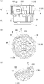
- FIG. 5A is a cross-sectional view taken along the line A
- FIG. 5C is an enlarged view inside the frame B in FIG.
- FIG. 6A is a side view of the female connector assembled to the fitting ring with the leaf spring protruding from the fitting ring.
- FIG. 6B is a side view of FIG.
- FIG. 6C is a cross-sectional view taken along the arrow C
- FIG. 6C is an enlarged view in the frame D of FIG. FIG.
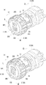
- FIG. 7A is a perspective view showing a female connector connected to a male connector
- FIG. 7A shows a state in which the leaf spring is bent in the fitting ring
- FIG. 7B shows a state in which the leaf spring protrudes from the fitting ring. Indicates the state.
- FIGS. 1 and 2 are perspective views of the connector device according to the present embodiment.
- FIG. 1 shows a state before the fitting ring 2 is assembled to the female connector 1
- FIG. 2 shows a state after the fitting ring 2 is assembled to the female connector 1.
- FIG. 3 is a perspective view of the female connector 1 as seen from a direction different from FIGS. 1 and 2.
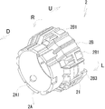
- FIG. 4 is a perspective view of the fitting ring 2 as seen from a direction different from FIGS. 1 and 2. Note that the vertical and horizontal directions used in the following description are shown in the drawings used for the description.
- the upper direction which is one direction along the fitting direction of both connectors is “U”
- the lower direction which is the other direction along the fitting direction of both connectors is “D”
- the circumferential direction of both connectors The left direction, which is one direction along, is denoted as “L”
- the right direction, which is the other direction along the circumferential direction of both connectors is denoted as “R”.
- the top, bottom, left and right are described for explanation, and of course may be different from the actual arrangement.
- the connector device is configured to connect a female connector 1 to which a fitting ring 2 is attached to a male connector 3.
- the male connector 3 includes a columnar main body 3A provided with a terminal cavity, and a cylindrical adherend 3B extending upward from the upper end of the main body 3A.
- the terminal held in the terminal cavity of the main body 3A has a tip projecting into the adherend portion 3B.
- a guide groove 31 is formed on the outer peripheral surface of the adherend portion 3B.
- the guide groove 31 extends spirally in the clockwise direction about the axis of the adherend portion 3B from the upper end of the adherend portion 3B downward.
- a pair of guide protrusions 32 extending in parallel with each other along the axis of the adherend portion 3B are formed on the inner peripheral surface of the adherend portion 3B downward from the upper end of the adherend portion 3B.
- the female connector 1 includes a columnar mounting portion 1A having a terminal cavity, and extends upward from the upper end of the mounting portion 1A. And a column-shaped supported portion 1B.
- An insertion hole through which a terminal of the male connector 3 is inserted when the female connector 1 and the male connector 3 are connected is opened on the lower surface of the mounting portion 1A.
- the terminal of the male connector 3 is connected to the terminal in the mounting portion 1A through the insertion hole.
- On the outer peripheral surface of the mounting portion 1A a guide portion 1A1 extending from the upper end to the lower end of the mounting portion 1A along the axis of the mounting portion 1A is formed. *
- the supported portion 1B has a larger outer diameter than the mounting portion 1A, and has a cylindrical shape whose axial center coincides with the mounting portion 1A. From the outer peripheral edge of the upper surface 1C of the supported portion 1B, flat regulation plates 1B2, 1B3, 1B4 extend with a predetermined width along the peripheral edge of the supported portion 1B. A locking groove extending along the circumferential direction of the supported portion 1B over the entire circumference of the supported portion 1B at the intermediate portion of the outer peripheral surface of the supported portion 1B located below the regulating plates 1B2, 1B3, 1B4 1B1 is formed.
- the outer peripheral surface of the supported portion 1B extends along the circumferential direction of the supported portion 1B from the lower end of the locking groove 1B1 to the lower end of the supported portion 1B.
- a notch 11 extending over a predetermined length is formed.
- the notch portion 11 is formed by thinning the outer peripheral portion of the supported portion 1B by a certain thickness, and from the side wall on the terminal end side in the counterclockwise direction of the supported portion 1B, the terminal end side in the clockwise direction
- a flat plate spring 12 extends toward the side wall.
- the fitting ring 2 has a cylindrical shape having a warped portion 2 A and a diameter-expanded portion 2 B. Yes.
- a guide projection 2A1 protrudes from the inner surface of the reduced part 2A toward the inside of the reduced part 2A.
- the enlarged diameter portion 2B gradually increases in diameter from the upper end of the reduced diameter portion 2A and extends upward, and then extends upward while maintaining the same diameter so that the axial center of the reduced diameter portion 2A coincides.
- a flat plate-like movement restricting piece 2B3 extends upward from the upper end of the enlarged diameter portion 2B.
- a plurality of locking plates 2B1 are provided at the upper end of the enlarged diameter portion 2B.
- Each locking plate 2B1 is formed by providing a pair of notches extending downward from the upper end of the enlarged diameter portion 2B, and includes an engaging protrusion on the inner surface of the upper end.
- the opening part 21 which has a rectangular opening shape and penetrated the surrounding wall of the enlarged diameter part 2B is formed in the surrounding wall of the enlarged diameter part 2B located under the movement control piece 2B3.
- the enlarged-diameter portion 2B has an L-shaped notch that extends downward from the upper end of the enlarged-diameter portion 2B and then extends along the circumferential direction of the enlarged-diameter portion 2B toward the lower side of the contact tongue 2B2.
- 2B4 is formed.
- the peripheral wall of the enlarged diameter portion 2B located on the upper end side of the notch 2B4 constitutes an elastic arm 2B5. From the upper end surface of the elastic arm 2B5, a flat contact tongue piece 2B2 extends upward.
- the female connector 1 is inserted into the enlarged diameter portion 2B of the fitting ring 2 from the mounting portion 1A side, and the outer peripheral surface of the supported portion 1B is the inner circumference of the enlarged diameter portion 2B. It faces the surface and is held by the fitting ring 2 as shown in FIG. A gap is provided between the mounting portion 1 A of the female connector 1 held by the fitting ring 2 and the warped portion 2 A of the fitting ring 2.
- the fitting ring 2 holding the female connector 1 is restricted from moving in the vertical direction by the locking projection provided on the locking plate 2B1 being locked in the locking groove 1B1 of the female connector 1. Further, the fitting ring 2 is guided by the locking protrusion 1B1 of the locking plate 2B1 in the locking groove 1B1 of the female connector 1, and is movable along the circumferential direction of the female connector 1. As shown in FIGS. 6 (a) to 6 (c), the fitting ring 2 is rotated clockwise by the movement restricting piece 2B3 coming into contact with the end face in the counterclockwise direction of the restricting plate 1B3 provided in the female connector 1. Restricted to move to. Although not shown, movement in the counterclockwise direction is restricted by the movement restricting piece 2B3 coming into contact with the end face in the clockwise direction of the restricting plate 1B4.
- the leaf spring 12 of the female connector 1 is elastically contacted with the inner peripheral surface of the enlarged diameter portion 2B provided in the fitting ring 2 and is notched.
- the restriction plate 1B3 of the female connector 1 and the movement restricting piece 2B3 are bent toward the portion 11 side as shown in FIGS. 6 (a) to 6 (c) and 7 (b).
- the tip protrudes from the opening 21 to the outside of the enlarged diameter portion 2B.
- connection work between the female connector 1 and the male connector 3 to which the fitting ring 2 is assembled is performed in a state (not shown) in which the restricting plate 1B4 of the female connector 1 and the movement restricting piece 2B3 of the fitting ring 2 are in contact with or close to each other. .
- the attached portion 3B of the male connector 3 is positioned between the contracted portion 2A and the mounting portion 1A.
- the guide portion 1A1 of the female connector 1 is inserted between the pair of guide protrusions 32 of the attachment portion 3B, and the guide protrusion 2A1 of the fitting ring 2 is inserted into the guide groove. Enter 31.
- the fitting ring 2 When the fitting ring 2 is rotated clockwise with respect to the male connector 3 in this state, the fitting ring 2 is guided by the guide protrusion 2A1 with the guide groove 31 and is rotated clockwise with respect to the male connector 3. Move downward while rotating.
- the female connector 1 is guided downward by a pair of guide protrusions 32 while the guide portion 1A1 is guided in the circumferential direction with respect to the male connector 3 and the vertical position with respect to the fitting ring 2 is kept constant. Moving. At this time, the fitting ring 2 is rotated clockwise with respect to the female connector 1 while the locking projection of the locking plate 2B1 is guided by the locking groove 1B1 provided in the supported portion 1B of the female connector 1.
- the contact tongue piece 2B2 When the fitting ring 2 rotates clockwise with respect to the female connector 1 as the female connector 1 and the fitting ring 2 move downward, the contact tongue piece 2B2, the movement restricting piece 2B3, and the opening 21 are also formed. It moves clockwise with respect to the female connector 1. Thereafter, when the contact tongue piece 2B2 contacts the restriction plate 1B2, the elastic arm 2B5 bends downward into the notch 2B4, and the contact tongue piece 2B2 passes through the restriction plate 1B2 as shown in FIG. Then, the bending of the elastic arm 2B5 is released.
- the leaf spring 12 projects the tip to the outside of the enlarged diameter portion 2B from the opening 21 that has moved to the position where the tip of the leaf spring 12 is disposed (FIG. 6A). (See also FIG. 6 (c)). Accordingly, the restricting plate 1B3 of the female connector 1 and the movement restricting piece 2B3 of the fitting ring 2 come into contact with each other, and the clockwise rotation of the fitting ring 2 with respect to the female connector 1 is also restricted. Further, the guide protrusion 2A1 of the fitting ring 2 comes into contact with the end portion of the guide groove 31 of the male connector 3, and the clockwise rotation of the fitting ring 2 with respect to the male connector 3 is also restricted.
- the opening 21 moves in the circumferential direction of the fitting ring 2 along the outer peripheral surface of the female connector 1 as the fitting ring 2 rotates, so that the female connector 1 and the male connector 3 are completely connected.
- the leaf spring 12 elastically contacting the inner peripheral surface of the fitting ring 2 protrudes from the opening 21 to the outside of the fitting ring 2.
- the operator confirms that the leaf spring 12 has come into contact with the hand holding the fitting ring 2 in order to rotate the fitting ring 2 with respect to the male connector 3. It can be seen that the connector 3 is completely fitted. Therefore, it is possible to reliably notify the operator of the complete fitting between the female connector 1 and the male connector 3 without being affected by the work environment.
- the guide protrusion 2A1 of the fitting ring 2 is guided by the guide groove 31 of the male connector 3 and the rotating fitting ring 2 is pulled into the male connector 3 side.
- the guide groove of the fitting ring 2 may be guided by the guide protrusion of the male connector 3.
- the said embodiment demonstrated the case where the guide part 1A1 of the female connector 1 was guided to the axial center direction of the male connector 3 with the guide protrusion 32 of the male connector 3, the guide method of the female connector 1 with respect to the male connector 3 was demonstrated.
- the guide protrusion of the female connector 1 may be guided by the guide portion of the male connector 3.
- the method of rotatably supporting the female connector 1 with the fitting ring 2 is arbitrary, and the locking plate provided in the female connector 1 may be locked in the locking groove provided in the fitting ring 2.
- the case where the contact tongue 2B2 of the fitting ring 2 contacts the restriction plate 1B2 of the female connector 1 before the female connector 1 and the male connector 3 are completely fitted has been described. It is good also as a structure which is not provided with the tongue piece 2B2 and the control board 1B2.
- the leaf spring protruding from the opening abuts on the hand holding the fitting ring, so that the complete fitting between the connectors is surely notified without being affected by the working environment. There is an effect that can be.
Landscapes
- Details Of Connecting Devices For Male And Female Coupling (AREA)
Abstract
作業環境の影響を受けることなく、コネクタ同士の完全嵌合を知らせることのできるコネクタ装置を提供する。 コネクタ装置は、嵌合リング(2)に回転自在に収容された雌コネクタ(1)を、雄コネクタ(3)に対する雌コネクタ(1)の嵌合方向に嵌合リング(2)を回転させながら引き込むことで、両コネクタ(1,3)同士が接続される。雌コネクタ(1)は、嵌合リング(2)の内周面に弾接する板バネ(12)を備えている。嵌合リング(2)は、周壁に開口部(21)を備えている。嵌合リング(2)が雄コネクタ(3)に対して回転すると、雌コネクタ(1)の外周面に沿って嵌合リング(2)の周方向に移動し、両コネクタ(1,3)同士の完全嵌合時には開口部(21)から板バネ(12)が嵌合リング(2)の外側に突出する。
Description
本発明は、嵌合リングに回転自在に収容された第1のコネクタを、回転する嵌合リングと共に第2のコネクタに対する第1のコネクタの嵌合方向に引き込むことで、両コネクタ同士が接続される回転嵌合式のコネクタ装置に関する。
この種のコネクタ装置は、下記の特許文献1~4に開示されている。下記の特許文献1では、噛み合わせリングに収容された雄型コネクタが、噛み合わせリングが回転することで雌型コネクタに接続される。両コネクタの完全嵌合時、噛み合わせリングが備える可撓係止アームの係止爪が、雄型コネクタの検知用係止突部を乗り越え、そのとき可撓係止アームの段部が検知用係止突部に当接してロック音が発生する。
下記の特許文献2では、回動部材に収容されたコネクタ主部が、回動部材が回転することで相手方コネクタに接続される。コネクタ主部と相手方コネクタとの完全嵌合時には、回動部材が備える係止アームの係止片がコネクタ主部の誘導部から係合部へ導かれて係止アームの弾性変形が解除される。このとき、係止片が係合部に係合して、ロック音が発生する。
下記の特許文献3では、回動部材に収容された雄コネクタが、回動部材が回転することで雌コネクタに接続される。両コネクタの完全嵌合時には、回動部材が備える係合アームの突部が雄コネクタの係合凹部に係合し、突部と係合凹部とが当接してロック音が発生する。
下記の特許文献4では、回動部材に収容された雄コネクタが、回動部材が回転することで雌コネクタに接続される。両コネクタの嵌合直後には、回動部材に支持された嵌合検知部材の一端が、他方のコネクタが備える環状壁の摺接面から当接終了端に落ち込んで、嵌合検知部材の他端の弾性片が弾性復帰し、嵌合検知部材が嵌合開始前の状態に戻る。
アームの当接に伴い生じるロック音で完全嵌合を知らせる特許文献1~3の方法では、周囲の騒音でロック音がかき消されたり、他の音をロック音と誤認する虞があった。また、嵌合検知部材の目視でコネクタ同士の完全嵌合を知らせる特許文献4の方法では、暗い場所での作業や周辺部品等の影響を受ける虞があった。
本発明は斯かる課題に鑑みてなされたもので、作業環境の影響を受けることなく、コネクタ同士の完全嵌合を知らせることのできるコネクタ装置を提供することを目的とする。
このような目的を達成するために、本発明のコネクタ装置は、嵌合リングに回転自在に収容された第1のコネクタを、前記嵌合リングを回転させることによって第2のコネクタに対する前記第1のコネクタの嵌合方向に引き込むことで、両コネクタ同士が接続されるコネクタ装置であって、前記第1のコネクタが、前記嵌合リングの内周面に弾接する板バネを備え、前記嵌合リングが、両コネクタ同士の完全嵌合時に前記板バネと向き合う位置に、前記板バネを前記嵌合リングの外側に突出させるための開口部を有することを特徴とする。
また、本発明のコネクタ装置は、周壁の内面に形成されたガイド突起と、前記周壁に形成された係止板と、前記周壁を貫通した開口部とを有した円筒状の嵌合リングと、前記嵌合リングの周方向に沿って回転自在に前記嵌合リング内に収容された本体と、前記本体の外周面に周方向に沿って延びて前記係止板をガイドする係止溝と、前記本体に形成されたガイド部とを有した雌コネクタと、円筒状の被着部と、前記被着部の外周面に螺旋状に延びて前記ガイド突起をガイドするガイド溝と、前記被着部の内周面に前記被着部の軸心方向に沿って延びて前記ガイド部をガイドするガイド突条とを有した雄コネクタとを備え、前記雌コネクタが、前記周壁の内周面に弾接する板バネを外周面に備え、前記周壁が、前記雌コネクタと前記雄コネクタとの完全嵌合時に前記板バネと向き合う位置に、前記板バネを前記嵌合リングの外側に突出させるための開口部を備えることを特徴とする。
また、本発明のコネクタ装置は、周壁の内面に形成されたガイド突起と、前記周壁に形成された係止板と、前記周壁を貫通した開口部とを有した円筒状の嵌合リングと、前記嵌合リングの周方向に沿って回転自在に前記嵌合リング内に収容された本体と、前記本体の外周面に周方向に沿って延びて前記係止板をガイドする係止溝と、前記本体に形成されたガイド部とを有した雌コネクタと、円筒状の被着部と、前記被着部の外周面に螺旋状に延びて前記ガイド突起をガイドするガイド溝と、前記被着部の内周面に前記被着部の軸心方向に沿って延びて前記ガイド部をガイドするガイド突条とを有した雄コネクタとを備え、前記雌コネクタが、前記周壁の内周面に弾接する板バネを外周面に備え、前記周壁が、前記雌コネクタと前記雄コネクタとの完全嵌合時に前記板バネと向き合う位置に、前記板バネを前記嵌合リングの外側に突出させるための開口部を備えることを特徴とする。
本発明によれば、開口部から突出した板バネが嵌合リングを把持した手に当接することで、両コネクタ同士の完全嵌合を、作業環境の影響を受けずに確実に知らせることができる。
以下、図面を参照して、本発明の一実施形態を説明する。
図1,2は、本実施形態のコネクタ装置の斜視図であり、図1は雌コネクタ1に対する嵌合リング2の組付前,図2は雌コネクタ1に対する嵌合リング2の組付後を示している。図3は、雌コネクタ1を図1、図2とは異なる方向から見た斜視図である。図4は、嵌合リング2を図1、図2とは異なる方向から見た斜視図である。なお、以下の説明で用いる上下,左右の各方向は説明に用いる各図に示している。各図において、両コネクタの嵌合方向に沿った一方向である上方向は「U」、両コネクタの嵌合方向に沿った他方向である下方向は「D」、両コネクタの周方向に沿った一方向である左方向は「L」、両コネクタの周方向に沿った他方向である右方向は「R」、とそれぞれ表記している。この上下,左右は説明のために記載したもので、実際の配置と異なってよいことはもちろんである。
図1,2は、本実施形態のコネクタ装置の斜視図であり、図1は雌コネクタ1に対する嵌合リング2の組付前,図2は雌コネクタ1に対する嵌合リング2の組付後を示している。図3は、雌コネクタ1を図1、図2とは異なる方向から見た斜視図である。図4は、嵌合リング2を図1、図2とは異なる方向から見た斜視図である。なお、以下の説明で用いる上下,左右の各方向は説明に用いる各図に示している。各図において、両コネクタの嵌合方向に沿った一方向である上方向は「U」、両コネクタの嵌合方向に沿った他方向である下方向は「D」、両コネクタの周方向に沿った一方向である左方向は「L」、両コネクタの周方向に沿った他方向である右方向は「R」、とそれぞれ表記している。この上下,左右は説明のために記載したもので、実際の配置と異なってよいことはもちろんである。
図1及び図2に示すように、コネクタ装置は、嵌合リング2が取り付けられた雌コネクタ1を、雄コネクタ3に接続するように構成されている。図1に示すように、雄コネクタ3は、端子キャビティを備えた円柱状の本体3Aと、本体3Aの上端から上方に延びた円筒状の被着部3Bとを備えている。本体3Aの端子キャビティ内に保持された端子は、被着部3B内に先端を突出させている。被着部3Bの外周面には、被着部3Bの上端から下方に向けて、被着部3Bの軸心を中心とする右回り方向に螺旋状に延びたガイド溝31が形成されている。また、被着部3Bの内周面には、被着部3Bの上端から下方に向けて、被着部3Bの軸心に沿って互いに平行に延びた一対のガイド突条32が形成されている。
図1~図3,及び図7(a)、図7(b)に示すように、雌コネクタ1は、端子キャビティを備えた円柱状の装着部1Aと、装着部1Aの上端から上方に延びた円柱状の被支持部1Bとを備えている。装着部1Aの下面には、雌コネクタ1と雄コネクタ3との接続時に雄コネクタ3の端子が挿通される挿通孔が開口している。雄コネクタ3の端子は、挿通孔を通して装着部1A内の端子と接続される。装着部1Aの外周面には、装着部1Aの上端から下端にかけて装着部1Aの軸心に沿って延びたガイド部1A1が形成されている。
被支持部1Bは、装着部1Aより大きな外径を有して、装着部1Aと軸心を一致させた円柱状を呈している。被支持部1Bの上面1Cの外周縁からは、平板状の規制板1B2,1B3,1B4が、被支持部1Bの周縁に沿って所定幅で延びている。規制板1B2,1B3,1B4の下方に位置する被支持部1Bの外周面の中間部には、被支持部1Bの全周に亘って被支持部1Bの周方向に沿って延びた係止溝1B1が形成されている。規制板1B3の下方に位置する被支持部1Bの外周面には、係止溝1B1の下端から被支持部1Bの下端にかけて、被支持部1Bの外周面を被支持部1Bの周方向に沿って所定長さに亘って延びた切欠部11が形成されている。切欠部11は、被支持部1Bの外周部を一定の厚さだけ肉薄に形成して構成されており、被支持部1Bの左回り方向の終端側の側壁からは、右回り方向の終端側の側壁側に向けて平板状の板バネ12が延びている。
図1,図2,図4,及び図7(a)、図7(b)に示すように、嵌合リング2は、縮経部2Aと拡径部2Bとを備えた円筒状を呈している。縮経部2Aの内面からは、ガイド突起2A1が縮経部2Aの内方に向けて突出している。拡径部2Bは、縮経部2Aの上端から徐々に拡径して上方に延びた後、同径を保って上方に延びて縮経部2Aと軸心を一致させている。
拡径部2Bの上端部からは、平板状の移動規制片2B3が上方に延びている。また、拡径部2Bの上端部には、複数の係止板2B1が設けられている。各係止板2B1は、拡径部2Bに上端から下方に向けて延びる一対の切り欠きを設けることで形成されており、上端部の内面には係止突起を備えている。また、移動規制片2B3の下方に位置する拡径部2Bの周壁には、矩形の開口形状を有して拡径部2Bの周壁を貫通した開口部21が形成されている。
拡径部2Bには、拡径部2Bの上端から下方に向けて延びた後、当接舌片2B2の下方に向けて拡径部2Bの周方向に沿って延びたL字状の切欠部2B4が形成されている。切欠部2B4の上端側に位置する拡径部2Bの周壁は、弾性アーム2B5を構成している。弾性アーム2B5の上端面からは、平板状の当接舌片2B2が上方に延びている。
次に、雌コネクタ1に対する嵌合リング2の取付構造について説明する。
雌コネクタ1は、図1に白抜きの矢印で示すように、嵌合リング2の拡径部2Bに装着部1A側から挿入され、被支持部1Bの外周面を拡径部2Bの内周面に向き合わせて、図2に示すように嵌合リング2に保持される。嵌合リング2に保持された雌コネクタ1の装着部1Aと、嵌合リング2の縮経部2Aとの間には間隙が設けられている。
雌コネクタ1を保持した嵌合リング2は、係止板2B1が備える係止突起が雌コネクタ1の係止溝1B1に係止することで、上下方向への移動を規制される。また、嵌合リング2は、雌コネクタ1の係止溝1B1で係止板2B1の係止突起をガイドされ、雌コネクタ1の周方向に沿って移動自在となっている。嵌合リング2は、図6(a)~図6(c)に示すように、雌コネクタ1が備える規制板1B3の左回り方向の終端面に移動規制片2B3が当接することで右回り方向への移動を規制される。また、図示しないが、規制板1B4の右回り方向の終端面に移動規制片2B3が当接することで左回り方向への移動を規制される。
雌コネクタ1の板バネ12は、図5(a)~図5(c),図7(a)に示すように、嵌合リング2が備える拡径部2Bの内周面に弾接して切欠部11側に撓んでおり、雌コネクタ1の規制板1B3と移動規制片2B3とが当接又は互いに近接した状態になると、図6(a)~図6(c),図7(b)に示すように開口部21から拡径部2Bの外側に先端を突出させる。
次に、嵌合リング2が組み付けられた雌コネクタ1を、雄コネクタ3と接続する際の動作について説明する。
嵌合リング2が組み付けられた雌コネクタ1と雄コネクタ3との接続作業は、雌コネクタ1の規制板1B4と嵌合リング2の移動規制片2B3が当接又は近接した図示しない状態で行われる。雌コネクタ1と雄コネクタ3との接続の際には、嵌合リング2が組み付けられた雌コネクタ1を、縮経部2Aと装着部1Aとの間に雄コネクタ3の被着部3Bが位置するように被着部3Bの上端側に配置し、雌コネクタ1のガイド部1A1を被着部3Bの一対のガイド突条32間に進入させると共に、嵌合リング2のガイド突起2A1をガイド溝31内に進入させる。この状態で、嵌合リング2を雄コネクタ3に対して右回り方向へ回転させると、嵌合リング2がガイド突起2A1をガイド溝31でガイドされて、雄コネクタ3に対して右回り方向へ回転しながら下方に移動する。また、雌コネクタ1は、一対のガイド突条32にガイド部1A1をガイドされて、雄コネクタ3に対する周方向への位置決めをされながら、嵌合リング2に対する上下位置を一定に保ちつつ、下方に移動する。このとき、嵌合リング2は、係止板2B1の係止突起を雌コネクタ1が被支持部1Bに備える係止溝1B1でガイドされて、雌コネクタ1に対して右回り方向へ回転する。
雌コネクタ1及び嵌合リング2の下方への移動に伴い、嵌合リング2が雌コネクタ1に対して右回り方向に回転すると、当接舌片2B2,移動規制片2B3,及び開口部21も雌コネクタ1に対して右回り方向に移動する。その後、当接舌片2B2が規制板1B2に当接すると弾性アーム2B5が下方に向けて切欠部2B4内に撓み、図7(a)に示すように当接舌片2B2が規制板1B2を通過すると、弾性アーム2B5の撓みが解けた状態となる。そして、雄コネクタ3が本体3Aに備える端子が嵌合リング2が縮経部2Aに備える挿通孔に挿入されて、縮経部2A内の端子に完全に接続される完全嵌合状態になると、図7(b)に示すように、板バネ12の先端の配置された位置まで移動してきた開口部21から、板バネ12が拡径部2Bの外側に先端を突出させる(図6(a)~図6(c)も参照)。これに伴い、雌コネクタ1の規制板1B3と嵌合リング2の移動規制片2B3とが当接して、雌コネクタ1に対する嵌合リング2の右回り方向への回転も規制される。また、嵌合リング2のガイド突起2A1が雄コネクタ3のガイド溝31の端部に当接し、雄コネクタ3に対する嵌合リング2の右回り方向への回転も規制される。
本実施形態によれば、嵌合リング2の回転に伴い開口部21が雌コネクタ1の外周面に沿って嵌合リング2の周方向に移動して、雌コネクタ1と雄コネクタ3とが完全嵌合すると、嵌合リング2の内周面に弾接した板バネ12が開口部21から嵌合リング2の外側に突出する。このため、作業者は、嵌合リング2を雄コネクタ3に対して回転させるために嵌合リング2を把持した手に板バネ12が当接したのを確認することで、雌コネクタ1と雄コネクタ3とが完全嵌合したのを知ることができる。従って、作業環境の影響を受けずに、雌コネクタ1と雄コネクタ3との完全嵌合を確実に作業者に知らせることができる。
なお、上記実施形態では、嵌合リング2のガイド突起2A1を雄コネクタ3のガイド溝31でガイドして、回転する嵌合リング2を雄コネクタ3側に引き込んだ場合について説明したが、雄コネクタ3に対する嵌合リング2のガイド方法は任意であり、例えば、嵌合リング2のガイド溝を雄コネクタ3のガイド突起でガイドしてもよい。
また、上記実施形態では、雌コネクタ1のガイド部1A1を雄コネクタ3のガイド突条32で雄コネクタ3の軸心方向にガイドした場合について説明したが、雄コネクタ3に対する雌コネクタ1のガイド方法は任意であり、例えば、雌コネクタ1のガイド突条を雄コネクタ3のガイド部でガイドしてもよい。
また、嵌合リング2で雌コネクタ1を回転自在に支持する方法は任意であり、嵌合リング2が備える係止溝に雌コネクタ1が備える係止板を係止させてもよい。また、上記実施形態では、雌コネクタ1と雄コネクタ3とが完全嵌合する前に嵌合リング2の当接舌片2B2が雌コネクタ1の規制板1B2に当接する場合について説明したが、当接舌片2B2及び規制板1B2を備えない構成としてもよい。
本発明を詳細にまた特定の実施態様を参照して説明したが、本発明の精神と範囲を逸脱することなく様々な変更や修正を加えることができることは当業者にとって明らかである。
本出願は、2010年3月29日出願の日本特許出願(特願2010-075253)に基づくものであり、その内容はここに参照として取り込まれる。
本発明のコネクタ装置によれば、開口部から突出した板バネが嵌合リングを把持した手に当接することで、両コネクタ同士の完全嵌合を、作業環境の影響を受けずに確実に知らせることができるという効果を奏する。
1 雌コネクタ(第1のコネクタ)
1A 装着部(本体)
1A1 ガイド部
1B 被支持部(本体)
1B1 係止溝
1B2,1B3,1B4 規制板
11 切欠部
12 板バネ
2 嵌合リング
2A 縮経部
2A1 ガイド突起
2B 拡径部
2B1 係止板
2B2 当接舌片
2B3 移動規制片
2B4 切欠部
2B5 弾性アーム
21 開口部
3 雄コネクタ(第2のコネクタ)
3A 本体
3B 被着部
31 ガイド溝
32 ガイド突条
1A 装着部(本体)
1A1 ガイド部
1B 被支持部(本体)
1B1 係止溝
1B2,1B3,1B4 規制板
11 切欠部
12 板バネ
2 嵌合リング
2A 縮経部
2A1 ガイド突起
2B 拡径部
2B1 係止板
2B2 当接舌片
2B3 移動規制片
2B4 切欠部
2B5 弾性アーム
21 開口部
3 雄コネクタ(第2のコネクタ)
3A 本体
3B 被着部
31 ガイド溝
32 ガイド突条
Claims (2)
- 嵌合リングに回転自在に収容された第1のコネクタを、前記嵌合リングを回転させることによって第2のコネクタに対する前記第1のコネクタの嵌合方向に引き込むことで、両コネクタ同士が接続されるコネクタ装置であって、
前記第1のコネクタは、前記嵌合リングの内周面に弾接する板バネを備え、
前記嵌合リングは、両コネクタ同士の完全嵌合時に前記板バネと向き合う位置に、前記板バネを前記嵌合リングの外側に突出させるための開口部を有するコネクタ装置。 - 周壁の内面に形成されたガイド突起と、前記周壁に形成された係止板と、前記周壁を貫通した開口部とを有した円筒状の嵌合リングと、
前記嵌合リングの周方向に沿って回転自在に前記嵌合リング内に収容された本体と、前記本体の外周面に周方向に沿って延びて前記係止板をガイドする係止溝と、前記本体に形成されたガイド部とを有した雌コネクタと、
円筒状の被着部と、前記被着部の外周面に螺旋状に延びて前記ガイド突起をガイドするガイド溝と、前記被着部の内周面に前記被着部の軸心方向に沿って延びて前記ガイド部をガイドするガイド突条とを有した雄コネクタとを備え、
前記雌コネクタは、前記周壁の内周面に弾接する板バネを外周面に備え、
前記周壁は、前記雌コネクタと前記雄コネクタとの完全嵌合時に前記板バネと向き合う位置に、前記板バネを前記嵌合リングの外側に突出させるための開口部を備えるコネクタ装置。
Applications Claiming Priority (2)
| Application Number | Priority Date | Filing Date | Title |
|---|---|---|---|
| JP2010075253A JP5638821B2 (ja) | 2010-03-29 | 2010-03-29 | コネクタ装置 |
| JP2010-075253 | 2010-03-29 |
Publications (1)
| Publication Number | Publication Date |
|---|---|
| WO2011122630A1 true WO2011122630A1 (ja) | 2011-10-06 |
Family
ID=44712325
Family Applications (1)
| Application Number | Title | Priority Date | Filing Date |
|---|---|---|---|
| PCT/JP2011/057830 Ceased WO2011122630A1 (ja) | 2010-03-29 | 2011-03-29 | コネクタ装置 |
Country Status (2)
| Country | Link |
|---|---|
| JP (1) | JP5638821B2 (ja) |
| WO (1) | WO2011122630A1 (ja) |
Cited By (3)
| Publication number | Priority date | Publication date | Assignee | Title |
|---|---|---|---|---|
| CN102655305A (zh) * | 2012-04-23 | 2012-09-05 | 中航光电科技股份有限公司 | 一种电连接器用连接到位识别机构 |
| CN102655304A (zh) * | 2012-04-23 | 2012-09-05 | 中航光电科技股份有限公司 | 一种连接到位可识别的连接器 |
| CN111473884A (zh) * | 2020-05-08 | 2020-07-31 | 许春生 | 一种减震稳固型热敏电阻 |
Families Citing this family (1)
| Publication number | Priority date | Publication date | Assignee | Title |
|---|---|---|---|---|
| JP6044874B2 (ja) * | 2013-05-28 | 2016-12-14 | 住友電装株式会社 | コネクタ |
Citations (2)
| Publication number | Priority date | Publication date | Assignee | Title |
|---|---|---|---|---|
| JPH04133337U (ja) * | 1991-06-03 | 1992-12-11 | 光洋電子工業株式会社 | 非接触検出器の取付構造 |
| JP2005267930A (ja) * | 2004-03-17 | 2005-09-29 | Yazaki Corp | 回転嵌合式コネクタ |
Family Cites Families (3)
| Publication number | Priority date | Publication date | Assignee | Title |
|---|---|---|---|---|
| US5662488A (en) * | 1996-10-31 | 1997-09-02 | Alden; Peter H. | Quick connect coupling system for rapidly joining connectors and/or other elongated bodies |
| JP3659539B2 (ja) * | 1996-11-25 | 2005-06-15 | 矢崎総業株式会社 | 電気コネクタの嵌合状態確認機構 |
| JP4805103B2 (ja) * | 2006-11-24 | 2011-11-02 | 矢崎総業株式会社 | 回転嵌合式コネクタにおける回動部材側コネクタ |
-
2010
- 2010-03-29 JP JP2010075253A patent/JP5638821B2/ja not_active Expired - Fee Related
-
2011
- 2011-03-29 WO PCT/JP2011/057830 patent/WO2011122630A1/ja not_active Ceased
Patent Citations (2)
| Publication number | Priority date | Publication date | Assignee | Title |
|---|---|---|---|---|
| JPH04133337U (ja) * | 1991-06-03 | 1992-12-11 | 光洋電子工業株式会社 | 非接触検出器の取付構造 |
| JP2005267930A (ja) * | 2004-03-17 | 2005-09-29 | Yazaki Corp | 回転嵌合式コネクタ |
Cited By (3)
| Publication number | Priority date | Publication date | Assignee | Title |
|---|---|---|---|---|
| CN102655305A (zh) * | 2012-04-23 | 2012-09-05 | 中航光电科技股份有限公司 | 一种电连接器用连接到位识别机构 |
| CN102655304A (zh) * | 2012-04-23 | 2012-09-05 | 中航光电科技股份有限公司 | 一种连接到位可识别的连接器 |
| CN111473884A (zh) * | 2020-05-08 | 2020-07-31 | 许春生 | 一种减震稳固型热敏电阻 |
Also Published As
| Publication number | Publication date |
|---|---|
| JP5638821B2 (ja) | 2014-12-10 |
| JP2011210445A (ja) | 2011-10-20 |
Similar Documents
| Publication | Publication Date | Title |
|---|---|---|
| TWI597903B (zh) | 槓桿連接器 | |
| US7632130B2 (en) | Electrical connector and connector assembly having inner and outer plug housings | |
| JP5649866B2 (ja) | ロック環を有する電気コネクタ | |
| JP4066951B2 (ja) | レバー式コネクタ | |
| JP4986970B2 (ja) | コネクタ | |
| JPWO2014192800A1 (ja) | コネクタ | |
| CN107408782B (zh) | 线缆连接器 | |
| JP2009170160A (ja) | レバー式コネクタ | |
| EP1571734B1 (en) | Connector apparatus with a mating detecting member called connector position assurance | |
| JP5638821B2 (ja) | コネクタ装置 | |
| JP5781846B2 (ja) | コネクタ装置 | |
| US11158978B2 (en) | Electrical connector having a locking clip | |
| TW201824660A (zh) | 電連接器及電連接器對 | |
| WO2013005630A1 (ja) | レバー式コネクタ | |
| CN105703126B (zh) | 电连接器和连接器端子 | |
| US10770834B2 (en) | Fitting connector | |
| JP6053743B2 (ja) | レバー付きコネクタ | |
| US20220042637A1 (en) | Device For Connecting Two Tubular Objects | |
| JP2011222275A (ja) | コネクタ装置 | |
| CN105703118B (zh) | 连接器端子 | |
| JP2011222274A (ja) | コネクタ装置 | |
| JP2020177811A (ja) | コネクタ | |
| JP2014220065A (ja) | コネクタ | |
| JP4738310B2 (ja) | 端子金具およびカードエッジコネクタ | |
| KR20140016379A (ko) | 레버식 커넥터 |
Legal Events
| Date | Code | Title | Description |
|---|---|---|---|
| 121 | Ep: the epo has been informed by wipo that ep was designated in this application |
Ref document number: 11762854 Country of ref document: EP Kind code of ref document: A1 |
|
| NENP | Non-entry into the national phase |
Ref country code: DE |
|
| 122 | Ep: pct application non-entry in european phase |
Ref document number: 11762854 Country of ref document: EP Kind code of ref document: A1 |